30
| Date post: | 16-Mar-2016 |
| Category: |
Documents |
| Upload: | eeweb-magazines |
| View: | 244 times |
| Download: | 0 times |
EEWebIssue 89
March 12, 2013
Electrical Engineering Community eeweb.com
VHDL101 -Part 2GettingStarted
TECHNICAL ARTICLE
Raspberry Pi -Part I
TECHNICAL ARTICLE
CEO, Spansion
JohnKispert
EEWeb PULSE TABLE OF CONTENTS
3Visit www.eeweb.com
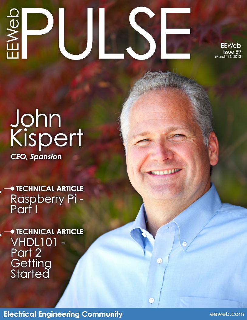
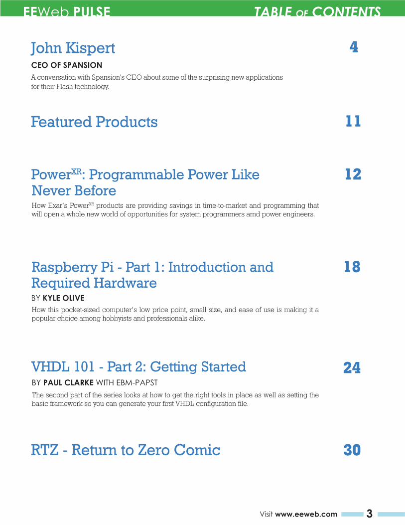
John Kispert CEO OF SPANSION
A conversation with Spansion’s CEO about some of the surprising new applications for their Flash technology.
How this pocket-sized computer’s low price point, small size, and ease of use is making it a popular choice among hobbyists and professionals alike.
RTZ - Return to Zero Comic
Featured Products
4
11
18
24
Raspberry Pi - Part 1: Introduction and
VHDL 101 - Part 2: Getting Started
30
How Exar’s PowerXR products are providing savings in time-to-market and programming that will open a whole new world of opportunities for system programmers amd power engineers.
12PowerXR: Programmable Power Like
BY KYLE OLIVE
Never Before
Required Hardware
BY PAUL CLARKE WITH EBM-PAPSTThe second part of the series looks at how to get the right tools in place as well as setting the basic framework so you can generate your first VHDL configuration file.
EEWeb PULSE INTERVIEW
4 EEWeb | Electrical Engineering Community
KispertJohnS PAN S I ON®
2726 Visit www.eeweb.com
EEWeb PULSE INTERVIEW
EEWeb | Electrical Engineering Community
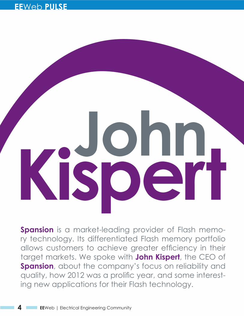
Spansion is a market-leading provider of Flash memo-ry technology. Its differentiated Flash memory portfolio allows customers to achieve greater efficiency in their target markets. We spoke with John Kispert, the CEO of Spansion, about the company’s focus on reliability and quality, how 2012 was a prolific year, and some interest-ing new applications for their Flash technology.

EEWeb PULSE INTERVIEW
5Visit www.eeweb.com
KispertJohnS PAN S I ON®
2726 Visit www.eeweb.com
EEWeb PULSE INTERVIEW
EEWeb | Electrical Engineering Community
EEWeb PULSE INTERVIEW
6 EEWeb | Electrical Engineering Community
How did you get started in the industry?
I grew up in New York and was actu-ally raised in the delicatessen busi-ness—if you’ve been to New York, you’d know that delis are a staple of the restaurant business there. I learned how to get up at 5 o’clock in the morning and work until midnight. So from a work ethic standpoint, ser-vice was a big part of that business. Given the diversity of the area, I also got to work with a lot of different kinds of people. I look back and think the long hours and hard work was just a tremendous experience—not fun at the time, but certainly a beneficial experience before college.
I went to Grinnel College in Iowa, which was a big change for someone from New York. I played bas-ketball and baseball there, so I’d say that my experi-ence was about learning self-reliance and leaving home and being much more vulnerable in a different envi-ronment. I met people from all over the world and from the athletic side of things, I was able to work with a wide variety of people.
From there, I went to busi-ness school at UCLA and after that, I got a job at IBM. At IBM I literally had a dif-ferent job every nine months and was able to travel all around the world. It was a really amazing experience and I’d say it was the equivalent of getting a PhD in high technology business—you spend time in every organization and every function and that was just a very rewarding expe-rience. After IBM, I moved out here to Silicon Valley and worked at a company called KLA Tencor, where I did almost the same things—I was the senior executive, CFO, COO and
president—and I was really able to grow with the company. I then came across Spansion, which I thought was an incredibly unique opportunity to turn around and re-focus a company that I felt had amazing people and technology. When you get the right people and the right technology to-gether, you can really do something good. The problem, of course, was that the company had very deep fi-nancial issues, so I spent the first 18 months revitalizing the balance sheet with the banks. This was in 2009, which was a very difficult time in the financial world. I managed to take care of the debt and got the capital structure as good as we could get it.
Since then, the last two years have been devoted to focusing on a strate-
Could you tell us a little more about Spansion?
We have around 3,000 employees and we are located in lots of places around the world. We have a design team in Israel and here in Silicon Valley. We have production partners and facili-ties in China, Austin Texas, Bangkok, and in Japan. We are wherever there is an electronics customer. We have over 8,000 customers in about 12 to 15 countries across the world.
As a specialty provider, we compete in service and in differentiated prod-ucts, so this has been a lot of fun as we have come up with differentiated solutions for our customers and really tailor Flash memory solutions for our customers. We have about 500 people who are dedicated around en-
gineering services to these customers. That provides us a value-added advan-tage over our competition. These products which we are designed into are long life-cycle products, so reli-ability and quality is really important. We stay away from products with short product life. One new solu-tion we just came out with is NAND. The NAND we ship is focused on high reliability and endures 100,000 cycles with anywhere from a 1 to 4 bit ECC. Our competition focuses primarily on the high density storage market and their high volume products
endure generally around 5,000 cycles and can require up to70bit ECC. Our strategy of focusing on reliability and quality has really helped us become profitable over the last two years, even in rough financial times.
Is Spansion a fabless company?As a part of the strategy, we are actu-
“When you get the right people
and the right technology to-
gether, you can really do some-
thing good.”
gy, which is around specialty memory for the embedded markets. Embed-ded markets are really everything in electronics, so we are very much into auto, communications, and all the in-dustrial segments and medical areas. The focus has been really everything I’ve learned over the years: customer service and quality. Spansion is doing very well with that.
EEWeb PULSE INTERVIEW
7Visit www.eeweb.com
ally “fab-lite.” We have a tremendous fab down in Austin that is essentially a “do-it-all” fab—it does copper, alu-minum, almost anything for us. We have partners in different parts of the world that are able to add capacity to the company really quickly. The fab we have in Austin is 20 years old and has an excellent team that allows us to have a lot of flexibility. That is the only fab we have. In the back end, all of the packaging—which is a big part of this business—we do in Bangkok, Thailand. With our network of partners around the world, when business surges, we can quickly outsource and utilize our partners to meet the demand.
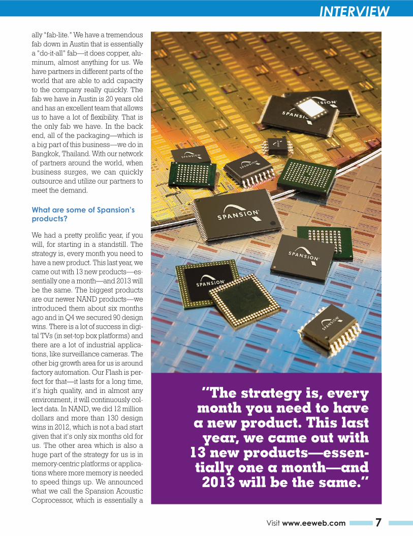
What are some of Spansion’s products?
We had a pretty prolific year, if you will, for starting in a standstill. The strategy is, every month you need to have a new product. This last year, we came out with 13 new products—es-sentially one a month—and 2013 will be the same. The biggest products are our newer NAND products—we introduced them about six months ago and in Q4 we secured 90 design wins. There is a lot of success in digi-tal TVs (in set-top box platforms) and there are a lot of industrial applica-tions, like surveillance cameras. The other big growth area for us is around factory automation. Our Flash is per-fect for that—it lasts for a long time, it’s high quality, and in almost any environment, it will continuously col-lect data. In NAND, we did 12 million dollars and more than 130 design wins in 2012, which is not a bad start given that it’s only six months old for us. The other area which is also a huge part of the strategy for us is in memory-centric platforms or applica-tions where more memory is needed to speed things up. We announced what we call the Spansion Acoustic Coprocessor, which is essentially a
“The strategy is, every month you need to have a new product. This last
year, we came out with 13 new products—essen-tially one a month—and 2013 will be the same.”
EEWeb PULSE INTERVIEW
8 EEWeb | Electrical Engineering Community
voice-recognition accelerator, and a first-of-its-kind system solution for voice recognition. It’s a chance for Spansion to custom design logic with high-speed memory, so it broad-ens our technology portfolio. What it does is accelerate and optimize voice-enabled interfaces with any machine. We’re focusing initially in voice recognition technology in au-tomobiles because it’s hard to find anyone who thinks theirs works well, so we see this as a huge opportunity. The biggest issue you have with voice recognition in a car is the speed and latency. When one person says some-thing and another person says the same thing, it sounds different given the accent or volume—it’s really a voice fingerprint. What it really gets down to is how many “fingerprints” you can store, match, and replicate quickly, so it’s really a memory-centric problem. We’ve been doing really well with this—our product improves voice recognition by about 50 percent.
Does Spansion plan on branching into more areas for NAND Flash?
Absolutely. We have multiple pro-grams which you’ll hear more about over the next year that will utilize all
the technology we have and the cus-tomers we have. These are customers that we already serve today and so we are listening to what their needs are and reacting to them with our next-generation technology. I think voice recognition and gesture recognition are two markets that are poised and ready, and we are focused on them across many different applications.
How are you improving your NOR products?
We are essentially looking at how to make NOR more applicable to all these new opportunities. That means more software, more user interface capabilities and more security—NOR is the most secure in storage devices. When you think of Enterprise level
“We’re focusing ini-tially in voice recogni-tion technology in au-tomobiles because it’s hard to find anyone who thinks theirs works well, so we see this as a huge opportunity.”
solutions, it’s a great opportunity for us in preventing unauthorized access to the content on a variety of devices, from customer to industrial. Also, automobile or airplane safety is a function which can be driven primarily by NOR sockets through the sophistication of the sensors and the random-read requirements of all these camera systems. NOR is also unique in that you can put it through extreme temperature ranges and know that it can stay for around 15 years and continuously operate and collect the sophisticated data that you need collected, collated, and analyzed.
What is Spansion’s vision for the next couple of years?I’d say that Flash memory matters more than ever right now, especially in the Internet of Things—there is a need for higher quality and durable technology for fast-access, newer and richer interfaces, so you can use voice or gesture recognition. All these things are happening now, so memory matters. Our vision at Spansion is pretty simple; we need to enable this kind of interactivity and security to add a user-friendly aspect to every platform with Spansion-grade quality products. Our backbone and DNA is customer service. Talk to any one of our customers—that’s what differentiates us as a company. We are able to react quickly to customer’s needs and create a solution for them.
For more information, visit:
www.spansion.com
EEWeb PULSE INTERVIEW
9Visit www.eeweb.comwww.partsim.com
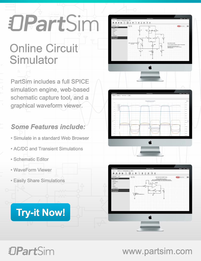
Online CircuitSimulator
PartSim includes a full SPICE simulation engine, web-based schematic capture tool, and a graphical waveform viewer.
Some Features include:• Simulate in a standard Web Browser
• AC/DC and Transient Simulations
• Schematic Editor• Schematic Editor
• WaveForm Viewer
• Easily Share Simulations
Try-it Now!
Optocouplers are the only isolation devices that meet or exceed the IEC 60747-5-5 International Safety Standard for insulation and isolation. Stringent evaluation tests show Avago’s optocouplers deliver outstanding performance on essential safety and deliver exceptional High Voltage protection for your equipment. Alternative isolation technologies such as ADI’s magnetic or TI’s capacitive isolators do not deliver anywhere near the high voltage insulation protection or noise isolation capabilities that optocouplers deliver.
For more details on this subject, read our white paper at: www.avagoresponsecenter.com/672
Take the Risk out of High Voltage Failure with Certifi ed Avago Optocouplers
Technology You Can Trust
IEC 60747-5-5 Certifi ed
FEATURED PRODUCTS
11Visit www.eeweb.com
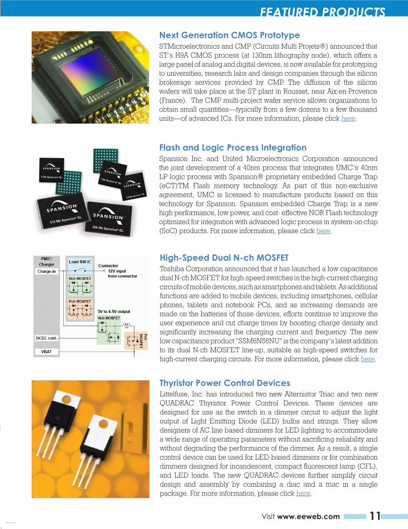
Next Generation CMOS PrototypeSTMicroelectronics and CMP (Circuits Multi Projets®) announced that ST’s H9A CMOS process (at 130nm lithography node), which offers a large panel of analog and digital devices, is now available for prototyping to universities, research labs and design companies through the silicon brokerage services provided by CMP. The diffusion of the silicon wafers will take place at the ST plant in Rousset, near Aix-en-Provence (France). The CMP multi-project wafer service allows organizations to obtain small quantities—typically from a few dozens to a few thousand units—of advanced ICs. For more information, please click here.
Flash and Logic Process IntegrationSpansion Inc. and United Microelectronics Corporation announced the joint development of a 40nm process that integrates UMC’s 40nm LP logic process with Spansion® proprietary embedded Charge Trap (eCT)TM Flash memory technology. As part of this non-exclusive agreement, UMC is licensed to manufacture products based on this technology for Spansion. Spansion embedded Charge Trap is a new high performance, low power, and cost- effective NOR Flash technology optimized for integration with advanced logic process in system-on-chip (SoC) products. For more information, please click here.
High-Speed Dual N-ch MOSFETToshiba Corporation announced that it has launched a low capacitance dual N-ch MOSFET for high-speed switches in the high-current charging circuits of mobile devices, such as smartphones and tablets. As additional functions are added to mobile devices, including smartphones, cellular phones, tablets and notebook PCs, and as increasing demands are made on the batteries of those devices, efforts continue to improve the user experience and cut charge times by boosting charge density and significantly increasing the charging current and frequency. The new low capacitance product “SSM6N58NU” is the company’s latest addition to its dual N-ch MOSFET line-up, suitable as high-speed switches for high-current charging circuits. For more information, please click here.
Thyristor Power Control DevicesLittelfuse, Inc. has introduced two new Alternistor Triac and two new QUADRAC Thyristor Power Control Devices. These devices are designed for use as the switch in a dimmer circuit to adjust the light output of Light Emitting Diode (LED) bulbs and strings. They allow designers of AC line based dimmers for LED lighting to accommodate a wide range of operating parameters without sacrificing reliability and without degrading the performance of the dimmer. As a result, a single control device can be used for LED-based dimmers or for combination dimmers designed for incandescent, compact fluorescent lamp (CFL), and LED loads. The new QUADRAC devices further simplify circuit design and assembly by combining a diac and a triac in a single package. For more information, please click here.
Optocouplers are the only isolation devices that meet or exceed the IEC 60747-5-5 International Safety Standard for insulation and isolation. Stringent evaluation tests show Avago’s optocouplers deliver outstanding performance on essential safety and deliver exceptional High Voltage protection for your equipment. Alternative isolation technologies such as ADI’s magnetic or TI’s capacitive isolators do not deliver anywhere near the high voltage insulation protection or noise isolation capabilities that optocouplers deliver.
For more details on this subject, read our white paper at: www.avagoresponsecenter.com/672
Take the Risk out of High Voltage Failure with Certifi ed Avago Optocouplers
Technology You Can Trust
IEC 60747-5-5 Certifi ed
EEWeb PULSE SPECIAL FEATURE
12 EEWeb | Electrical Engineering Community
Programmable PowerLike Never Before
The PowerXR programmable power managementt system by Exar Corporation is the first-ever program-mable switching regulator IC targeted to the network-ing, communications and industrial segments. This 4-output programmable device provides a better feature set, price for performance and cost structure than any other digital switching regulator on the market. System architects and program managers who are responsible for bringing end products to market will find that the PowerXR’s unique digital control loop and design tools will help them create differentiated end solutions. The use of FPGAs and DSPs can also help designers embed unique IP on the software and processors to help define how the power will interact with the rest of your system.
In an interview with Jon Cronk, the Technical Market-ing and Applications Director at Exar, he emphasized the importance of differentiation through software.
“Most of these hardware systems are all technical hardware components that people can buy anywhere,” Cronk states. “With a programmable power system, you now have another piece of hardware that’s avail-able to the software engineer to create additional differentiation.” Cronk also goes on to mention the benefits of the PowerXR products in the industrial space; “The programmability of the PowerXR products means your engineers can confidently move forward before you have the latest system chip in hand.”
PowerXR products come with an intuitive GUI-based design tool, demo boards and documentation to help lower the risk and provide an easier path to starting the programming process.
A variety of applications, such as industrial, servers, and communications infrastructure are seeing the value in the PowerXR’s telemetry and unprecedented
The programmability of the PowerXR products means your engineers can confidently move forward before
you have the latest system chip in hand.
time-to-market. Users are seeing the value within their end systems when they adopt this technology by adding additional differentiation to their hardware and reducing the time for programming by removing the need for soldering irons. Engineers can be more efficient based solely on what they can achieve by integrating the chip into the system and management of power through software. The most valuable thing about the PowerXR, according to Jon Cronk, is “the creative ways it can be leveraged in the system that
you have not yet contemplated.” With the PowerXR’s game-changing savings in time-to-market and ease of programmability, it can open a whole new world of possibilities for your system programmer, power engineers, and ultimately, your unique end product.
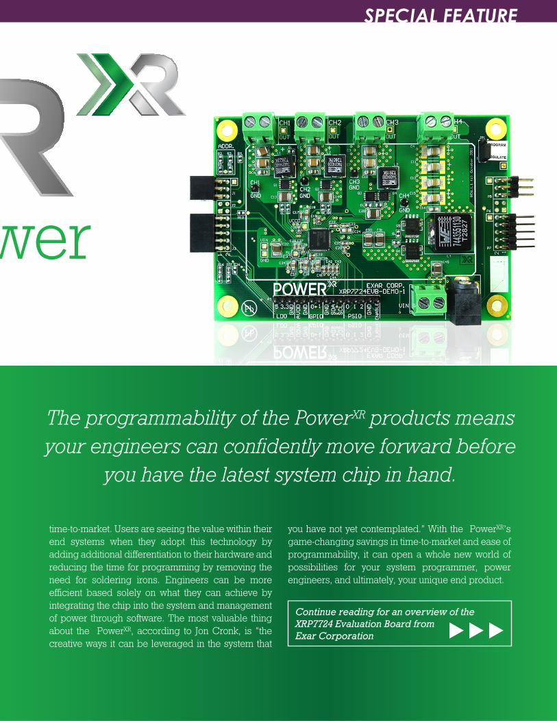
Continue reading for an overview of the XRP7724 Evaluation Board fromExar Corporation
EEWeb PULSE SPECIAL FEATURE
13Visit www.eeweb.com
Programmable PowerLike Never Before
The PowerXR programmable power managementt system by Exar Corporation is the first-ever program-mable switching regulator IC targeted to the network-ing, communications and industrial segments. This 4-output programmable device provides a better feature set, price for performance and cost structure than any other digital switching regulator on the market. System architects and program managers who are responsible for bringing end products to market will find that the PowerXR’s unique digital control loop and design tools will help them create differentiated end solutions. The use of FPGAs and DSPs can also help designers embed unique IP on the software and processors to help define how the power will interact with the rest of your system.
In an interview with Jon Cronk, the Technical Market-ing and Applications Director at Exar, he emphasized the importance of differentiation through software.
“Most of these hardware systems are all technical hardware components that people can buy anywhere,” Cronk states. “With a programmable power system, you now have another piece of hardware that’s avail-able to the software engineer to create additional differentiation.” Cronk also goes on to mention the benefits of the PowerXR products in the industrial space; “The programmability of the PowerXR products means your engineers can confidently move forward before you have the latest system chip in hand.”
PowerXR products come with an intuitive GUI-based design tool, demo boards and documentation to help lower the risk and provide an easier path to starting the programming process.
A variety of applications, such as industrial, servers, and communications infrastructure are seeing the value in the PowerXR’s telemetry and unprecedented
The programmability of the PowerXR products means your engineers can confidently move forward before
you have the latest system chip in hand.
time-to-market. Users are seeing the value within their end systems when they adopt this technology by adding additional differentiation to their hardware and reducing the time for programming by removing the need for soldering irons. Engineers can be more efficient based solely on what they can achieve by integrating the chip into the system and management of power through software. The most valuable thing about the PowerXR, according to Jon Cronk, is “the creative ways it can be leveraged in the system that
you have not yet contemplated.” With the PowerXR’s game-changing savings in time-to-market and ease of programmability, it can open a whole new world of possibilities for your system programmer, power engineers, and ultimately, your unique end product.
Continue reading for an overview of the XRP7724 Evaluation Board fromExar Corporation
EEWeb PULSE SPECIAL FEATURE
14 EEWeb | Electrical Engineering Community
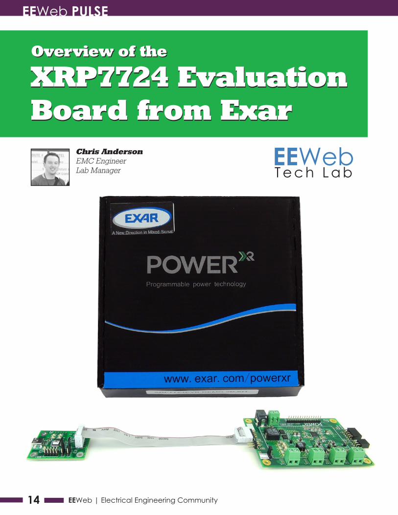
Overview of theOverview of the
XRP7724 EvaluationBoard from ExarXRP7724 Evaluation Board from Exar
EEWebT e c h L a b
Chris AndersonEMC EngineerLab Manager
EEWeb PULSE SPECIAL FEATURE
15Visit www.eeweb.com
What’s InsideThe device is centered around Exar’s XRP7724 quad-channel buck converter. Inside the box is the actual demo board with the XCM module, a USB drive with all of the documentation and software, a USB cable, and a “Quick Start” guide.
The board is centered around the XRP7724. Everything is essentially built into this component. It has the under-voltage lockout, over-temperature protection, and the entire power system built into the chip, other than the passives that surround it. There are power inputs where you can either use the header or the barrel connector. There are four regular voltage output channels and the USB I2C XCM controller connects straight into the device. Exar points out that you need to make sure you have this connection the correct way, otherwise you will end up frying your XCM module.
Getting StartedTo start using the board, install launch PowerArchitect™ version 5. When it comes up, you want to use the Get Started with EVB-DEMO1 board. Your computer might recognize the port that it’s on already, and if it doesn’t, click on “Tools,” go to “Boards,” and select the port that recognizes that it has the XCM chip. Once you’re there you can start looking around at the settings that they have pre-programmed for this evaluation board. There are start-up times, ramp times, different groups as well as the shut-downs.
Programming the FlashTo load the settings into the Flash non-volatile memory, go to “Tools,” and select “Program the Flash.” Hit “Flash” and it will clear the Flash , reprogram it, and inform you when the chip is reset. Go to “Tools” again and select “Dashboard,” which will show you a live shot of what is going on in your power system. One thing to note—I have a 12 volt stated wall wart plugged in and the XRP7724 says it’s actually operating at 17.4 volts, which will likely affect the operation of the chip, but we’ll turn it on for the purposes of this demo. You’ll see that they have a group setup. Group 1 includes Channel 1, Channel 2, and the 3.3 LDO and you’ll see that those are regulating at 3.3 volts. If you turn on Group 2, you’ll see Channels 3 and 4 come up and jump right to their set voltages as well. Even though you can’t see the start-up and shut-down ramps, they are going on.
If you go back one screen, you can see the group setup. Group 1 has Channel 1, Channel 2, and the 3.3 LDO and Group 2 has Channel 3 and Channel 4 and you’ll see that they have some different ramp rates set here, which are the shut-down ramp rates and they are the same as the startup ramp rates. If you want to get more into detail, you can change the defaults in the PowerArchitect program that will tell you the responses you can expect.
You can also look at the different channels and—based on the different hardware they have on the board and the settings that are already in here—you see that Bode diagram shift around. If you go back to the XRP7724 overview, you can see all of your different settings and change them around as much as you want. In this case, we are going to clear it, erase it, and reprogram it. After that, we’ll bring up the dashboard again and if I turn on Channel 1, you’ll see it ramp up to 5 volts and you’ll see my VCC moving around. This also displays all of your flags, so if you have a fault—if you’re over temperature or under temperature—it gives you all of the necessary status updates on the XRP7724 in real time.
ConclusionIn my opinion, the XRP7724 is an easy-to-use, easy-to-program voltage controller that is efficient in both size and power. If you are in infrastructure type applications such as servers or base stations, it should meet all of your needs.
To watch this review and others from EEWeb Tech Lab:
Click Here
Electric
al Engine
ering C
ommunity
EEWeb
ARTICLES
JOBS
COMMUNITY
DEVELOPMENT TOOLS
Dave BaarmanDirector Of
Advanced Technologies
Making WirelessTruly Wireless:
Need For UniversalWireless Power
Solution
"Sed ut perspiciatis unde omnis
iste natus error sit voluptatem
accusantium doloremque
laudantium, totam rem aperiam,
eaque ipsa quae ab illo inventore
veritatis et quasi architecto beatae vitae
dicta sunt explicabo. Nemo enim ipsam
voluptatem quia voluptas sit aspernatur aut odit
aut fugit, sed quia consequuntur magni dolores eos
qui ratione voluptatem sequi nesciunt. Neque porro
quisquam est, qui dolorem ipsum quia dolor sit amet, consectetur,
adipisci velit, sed quia non numquam eius modi tempora incidunt ut
labore et dolore magnam aliquam quaerat voluptatem. Ut enim ad
minima veniam, quis nostrum exercitationem ullam corporis suscipit
laboriosam, nisi ut aliquid ex ea commodi consequatur? Quis autem
vel eum iure reprehenderit qui in ea voluptate velit esse quam nihil
www.eeweb.com
JOINTODAY
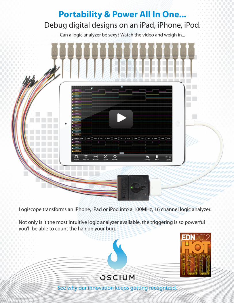
Portability & Power All In One...Debug digital designs on an iPad, iPhone, iPod.
Can a logic analyzer be sexy? Watch the video and weigh in...
Logiscope transforms an iPhone, iPad or iPod into a 100MHz, 16 channel logic analyzer.
Not only is it the most intuitive logic analyzer available, the triggering is so powerful you’ll be able to count the hair on your bug.
See why our innovation keeps getting recognized.
EEWeb PULSE TECH ARTICLE
18 EEWeb | Electrical Engineering Community
Kyle OliveComputer Engineering Student &
IEEE Student Branch ChairRaspberryIntroductionand RequiredHardware
PART 1:
The
Pi
Raspberry Pi is a trademark of the Raspberry Pi Foundation
EEWeb PULSE TECH ARTICLE
19Visit www.eeweb.com
Kyle OliveComputer Engineering Student &
IEEE Student Branch ChairRaspberryIntroductionand RequiredHardware
PART 1:
The
Pi Recently, interest in hobby electronics has grown dra-matically. With platforms like
the Arduino gaining popularity and achieving wide success in various retail markets, it’s no wonder that these kinds of hobby electronics have become more prevalent. Though similar to the Arduino, which is designed around a micro-controller and allows hobbyists to acquire and build various shields and add-ons for more functionality, the Raspberry Pi takes a different approach.
EEWeb PULSE TECH ARTICLE
20 EEWeb | Electrical Engineering Community
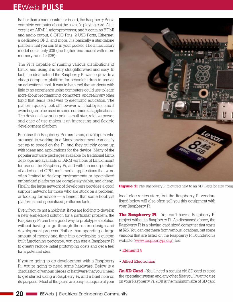
Rather than a microcontroller board, the Raspberry Pi is a complete computer about the size of a playing card. At its core is an ARM11 microprocessor, and it contains HDMI and audio output, 8 GPIO Pins, 2 USB Ports, Ethernet, a dedicated GPU, and more. It’s basically a standalone platform that you can fit in your pocket. The introductory model costs only $25 (the higher end model with more memory runs for $35).
The Pi is capable of running various distributions of Linux, and using it is very straightforward and easy. In fact, the idea behind the Raspberry Pi was to provide a cheap computer platform for schoolchildren to use as an educational tool. It was to be a tool that students with little to no experience using computers could use to learn more about programming, computers, and really any other topic that lends itself well to electronic education. The platform quickly took off however with hobbyists, and it even began to be used in some commercial applications. The device’s low price point, small size, relative power, and ease of use makes it an interesting and flexible development platform.
Because the Raspberry Pi runs Linux, developers who are used to working in a Linux environment can easily get up to speed on the Pi, and they quickly come up with ideas and applications for the device. Many of the popular software packages available for traditional Linux desktops are available on ARM versions of Linux meant for use on the Raspberry Pi, and with the incorporation of a dedicated GPU, multimedia applications that were often limited to desktop environments or specialized embedded platforms are completely viable, and cheap. Finally, the large network of developers provides a good support network for those who are stuck on a problem, or looking for advice — a benefit that some hobbyist platforms and specialized platforms lack.
Even if you’re not a hobbyist, if you are looking to develop a new embedded solution for a particular problem, the Raspberry Pi can be a good way to prototype a solution without having to go through the entire design and development process. Rather than spending a large amount of money and time into developing a custom built functioning prototype, you can use a Raspberry Pi to greatly reduce initial prototyping costs and get a feel for a potential idea.
If you’re going to do development with a Raspberry Pi, you’re going to need some hardware. Below is a discussion of various pieces of hardware that you’ll need to get started using a Raspberry Pi, and a brief note on its purpose. Most of the parts are easy to acquire at your
local electronics store, but the Raspberry Pi vendors listed below will also often sell you this equipment with your Raspberry Pi.
The Raspberry Pi – You can’t have a Raspberry Pi project without a Raspberry Pi. As discussed above, the Raspberry Pi is a playing-card sized computer that starts at $25. You can get these from various locations, but some vendors that are listed on the Raspberry Pi Foundation’s website (www.raspberrypi.org) are:
• Element14
• Allied Electronics
An SD Card – You’ll need a regular old SD card to store the operating system and any other files you’ll want to use on your Raspberry Pi. 2GB is the minimum size of SD card
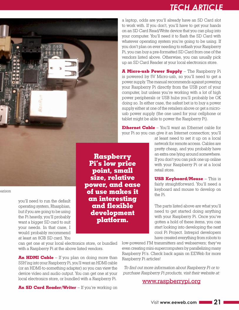
Figure 1: The Raspberry Pi pictured next to an SD Card for size comparison
EEWeb PULSE TECH ARTICLE
21Visit www.eeweb.com
Figure 1: The Raspberry Pi pictured next to an SD Card for size comparison
you’ll need to run the default operating system, Rhaspbian, but if you are going to be using the Pi heavily, you’ll probably want a bigger SD card to suit your needs. In that case, I would probably recommend at least an 8GB SD card. You can get one at your local electronics store, or bundled with a Raspberry Pi at the above listed vendors.
An HDMI Cable – If you plan on doing more than SSH’ing into your Raspberry Pi, you’ll want an HDMI cable (or an HDMI-to-something adapter) so you can view the device video and audio output. You can get one at your local electronics store, or bundled with a Raspberry Pi.
An SD Card Reader/Writer – If you’re working on
a laptop, odds are you’ll already have an SD Card slot to work with. If you don’t, you’ll have to get your hands on an SD Card Read/Write device that you can plug into your computer. You’ll need it to flash the SD Card with whatever operating system you’re going to be using. If you don’t plan on ever needing to reflash your Raspberry Pi, you can buy a pre-formatted SD Card from one of the vendors listed above. Otherwise, you can usually pick up an SD Card Reader at your local electronics store.
A Micro-usb Power Supply – The Raspberry Pi is powered by 5V Micro-usb, so you’ll need to get a power supply. The manual recommends against powering your Raspberry Pi directly from the USB port of your computer, but unless you’re working with a lot of high power peripherals or USB hubs you’ll probably be OK doing so. In either case, the safest bet is to buy a power supply either at one of the retailers above or get a micro-usb power supply (the one used for your cellphone or tablet might be able to power the Raspberry Pi).
Ethernet Cable – You’ll want an Ethernet cable for your Pi so you can give it an Internet connection; you’ll
at least need to set it up on a local network for remote access. Cables are pretty cheap, and you probably have an extra one lying around somewhere. If you don’t you can pick one up online with your Raspberry Pi or at a local retail store.
USB Keyboard/Mouse – This is fairly straightforward. You’ll need a keyboard and mouse to develop on the Pi.
The parts listed above are what you’ll need to get started doing anything with your Raspberry Pi. Once you’ve gotten a hold of these items, you can start looking into developing the next cool Pi Project. Intrepid developers have created everything from robots to
low-powered FM transmitters and webservers; they’ve even creating mini-supercomputers by parallelizing many Raspberry Pi’s. Check back again on EEWeb for more Raspberry Pi articles!
To find out more information about Raspberry Pi or to purchase Raspberry Pi products, visit their website at:
www.raspberrypi.org
Raspberry Pi’s low price point, small
size, relative power, and ease of use makes it an interesting and flexible development
platform.

BeStar®
ACOUSTICS & SENSORS
Teamwork • Technology • Invention • Listen • Hear
PRODUCTSSpeakers
Buzzers
Piezo Elements
Back-up Alarms
Horns
Sirens/Bells
Beacons
Microphones
Sensors
INDUSTRIESAutomotive
Durables
Medical
Industrial
Mobile
Fire / Safety
Security
Consumer
Leisure
QS9000 • TS/ ISO16949 • ISO14001 • ISO13485 • ISO9001
bestartech.com | [email protected] | 520.439.9204
Preferred acoustic componentsupplier to OEMs worldwide
www.partsim.com
PartSim includes a full SPICE simulation engine, web-based schematic capture tool, and a graphical waveform viewer.
Some Features include:• Simulate in a standard Web Browser• AC/DC and Transient Simulations• Schematic Editor• WaveForm Viewer• WaveForm Viewer• Easily Share Simulations
Online Circuit Simulator
Try-it Now!

NXP’s proven interface products enable medical and health system designers
to add features with minimal modifications. Within our portfolio you’ll find LCD
displays and capacitive touch interfaces, system connectivity bridges & UARTs, LED
controllers, real-time clocks, and I2C-bus peripherals & enablers.
To learn more, visit http://www.nxp.com/campaigns/medical-interfaces/2248
Breathe new life into medical product interfaces
EEWeb PULSE TECH ARTICLE
24 EEWeb | Electrical Engineering Community
101Getting Started
Paul ClarkeElectronics Design
Engineer
VHDLPart 2

EEWeb PULSE TECH ARTICLE
25Visit www.eeweb.com
101Getting Started
Paul ClarkeElectronics Design
Engineer
VHDLPart 2
When you first get started with VHDL, a little bit of setting up needs to be done before you can really sink your teeth in. This should not put you off, however, as you only have to do it once. In this article we will look at getting all the tools in place, setting up the basic framework, and generating your first VHDL configuration file.
EEWeb PULSE TECH ARTICLE
26 EEWeb | Electrical Engineering Community
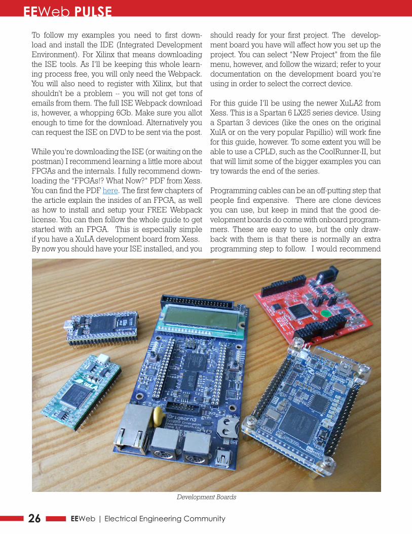
To follow my examples you need to first down-load and install the IDE (Integrated Development Environment). For Xilinx that means downloading the ISE tools. As I’ll be keeping this whole learn-ing process free, you will only need the Webpack. You will also need to register with Xilinx, but that shouldn’t be a problem -- you will not get tons of emails from them. The full ISE Webpack download is, however, a whopping 6Gb. Make sure you allot enough to time for the download. Alternatively you can request the ISE on DVD to be sent via the post.
While you’re downloading the ISE (or waiting on the postman) I recommend learning a little more about FPGAs and the internals. I fully recommend down-loading the “FPGAs!? What Now?” PDF from Xess. You can find the PDF here. The first few chapters of the article explain the insides of an FPGA, as well as how to install and setup your FREE Webpack license. You can then follow the whole guide to get started with an FPGA. This is especially simple if you have a XuLA development board from Xess.By now you should have your ISE installed, and you
should ready for your first project. The develop-ment board you have will affect how you set up the project. You can select “New Project” from the file menu, however, and follow the wizard; refer to your documentation on the development board you’re using in order to select the correct device.
For this guide I’ll be using the newer XuLA2 from Xess. This is a Spartan 6 LX25 series device. Using a Spartan 3 devices (like the ones on the original XulA or on the very popular Papillio) will work fine for this guide, however. To some extent you will be able to use a CPLD, such as the CoolRunner-II, but that will limit some of the bigger examples you can try towards the end of the series.
Programming cables can be an off-putting step that people find expensive. There are clone devices you can use, but keep in mind that the good de-velopment boards do come with onboard program-mers. These are easy to use, but the only draw-back with them is that there is normally an extra programming step to follow. I would recommend
Development Boards
EEWeb PULSE TECH ARTICLE
27Visit www.eeweb.com
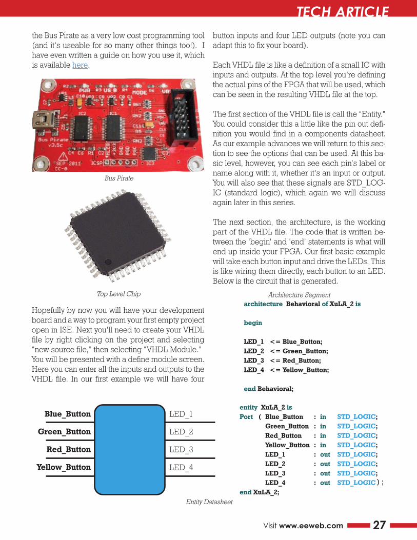
the Bus Pirate as a very low cost programming tool (and it’s useable for so many other things too!). I have even written a guide on how you use it, which is available here.
button inputs and four LED outputs (note you can adapt this to fix your board).
Each VHDL file is like a definition of a small IC with inputs and outputs. At the top level you’re defining the actual pins of the FPGA that will be used, which can be seen in the resulting VHDL file at the top.
The first section of the VHDL file is call the “Entity.” You could consider this a little like the pin out defi-nition you would find in a components datasheet. As our example advances we will return to this sec-tion to see the options that can be used. At this ba-sic level, however, you can see each pin’s label or name along with it, whether it’s an input or output. You will also see that these signals are STD_LOG-IC (standard logic), which again we will discuss again later in this series.
The next section, the architecture, is the working part of the VHDL file. The code that is written be-tween the ‘begin’ and ‘end’ statements is what will end up inside your FPGA. Our first basic example will take each button input and drive the LEDs. This is like wiring them directly, each button to an LED. Below is the circuit that is generated.
Hopefully by now you will have your development board and a way to program your first empty project open in ISE. Next you’ll need to create your VHDL file by right clicking on the project and selecting “new source file,” then selecting “VHDL Module.” You will be presented with a define module screen. Here you can enter all the inputs and outputs to the VHDL file. In our first example we will have four
LED_1entity XuLA_2 isPort ( Blue_Button : in STD_LOGIC; Green_Button : in STD_LOGIC; Red_Button : in STD_LOGIC; Yellow_Button : in STD_LOGIC; LED_1 : out STD_LOGIC; LED_2 : out STD_LOGIC; LED_3 : out STD_LOGIC; LED_4 : out STD_LOGIC;end XuLA_2;
LED_2
LED_3
LED_4
Blue_Button
Green_Button
Red_Button
Yellow_Button
) ;
architecture Behavioral of XuLA_2 is
begin
LED_1 <= Blue_Button;LED_2 <= Green_Button;LED_3 <= Red_Button;LED_4 <= Yellow_Button;
end Behavioral;
Bus Pirate
Top Level Chip Architecture Segment
Entity Datasheet
EEWeb PULSE TECH ARTICLE
28 EEWeb | Electrical Engineering Community
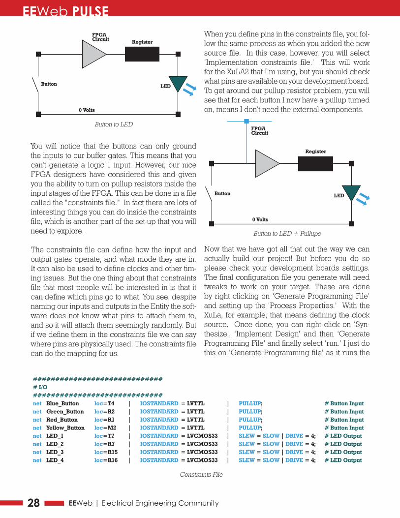
You will notice that the buttons can only ground the inputs to our buffer gates. This means that you can’t generate a logic 1 input. However, our nice FPGA designers have considered this and given you the ability to turn on pullup resistors inside the input stages of the FPGA. This can be done in a file called the “constraints file.” In fact there are lots of interesting things you can do inside the constraints file, which is another part of the set-up that you will need to explore.
The constraints file can define how the input and output gates operate, and what mode they are in. It can also be used to define clocks and other tim-ing issues. But the one thing about that constraints file that most people will be interested in is that it can define which pins go to what. You see, despite naming our inputs and outputs in the Entity the soft-ware does not know what pins to attach them to, and so it will attach them seemingly randomly. But if we define them in the constraints file we can say where pins are physically used. The constraints file can do the mapping for us.
When you define pins in the constraints file, you fol-low the same process as when you added the new source file. In this case, however, you will select ‘Implementation constraints file.’ This will work for the XuLA2 that I’m using, but you should check what pins are available on your development board. To get around our pullup resistor problem, you will see that for each button I now have a pullup turned on, means I don’t need the external components.
Now that we have got all that out the way we can actually build our project! But before you do so please check your development boards settings. The final configuration file you generate will need tweaks to work on your target. These are done by right clicking on ‘Generate Programming File’ and setting up the ‘Process Properties.’ With the XuLa, for example, that means defining the clock source. Once done, you can right click on ‘Syn-thesize’, ‘Implement Design’ and then ‘Generate Programming File’ and finally select ‘run.’ I just do this on ‘Generate Programming file’ as it runs the
FPGACircuit
Button
0 Volts
LED
Register
############################## I/O#############################net Blue_Button loc=T4 | IOSTANDARD = LVTTL | PULLUP; # Button Inputnet Green_Button loc=R2 | IOSTANDARD = LVTTL | PULLUP; # Button Inputnet Red_Button loc=R1 | IOSTANDARD = LVTTL | PULLUP; # Button Inputnet Yellow_Button loc=M2 | IOSTANDARD = LVTTL | PULLUP; # Button Inputnet LED_1 loc=T7 | IOSTANDARD = LVCMOS33 | SLEW = SLOW | DRIVE = 4; # LED Outputnet LED_2 loc=R7 | IOSTANDARD = LVCMOS33 | SLEW = SLOW | DRIVE = 4; # LED Outputnet LED_3 loc=R15 | IOSTANDARD = LVCMOS33 | SLEW = SLOW | DRIVE = 4; # LED Outputnet LED_4 loc=R16 | IOSTANDARD = LVCMOS33 | SLEW = SLOW | DRIVE = 4; # LED Output
FPGACircuit
Button
0 Volts
LED
Register
Button to LED
Button to LED + Pullups
Constraints File
EEWeb PULSE TECH ARTICLE
29Visit www.eeweb.com
others if required. If you get errors, check the files and settings again. I also recommend reading the Xess guide I commented on at the start as it has a comprehensive guide to setting up projects and programming.
Our final task again depends on your development board programming. Again follow your guides to program your board. For my example I need to open the Xess GXSLOAD application, drag over the ‘.bit’ file, and click load. The .bit file is the final configuration file that is sent to the target for con-figuration to take place.
Okay, so having four buttons turn on LEDs may not be that exciting but it’s an important first step. Getting your IDE development board set up and programmed for the first time means you now have your workflow in place. From now on each example will focus on the programming and use of VHDL, which will leave you to focus on the learning and not on the tools.
The files used in this example are available to download from https://github.com/monpjc/EE-WEB_VHDL_Setup
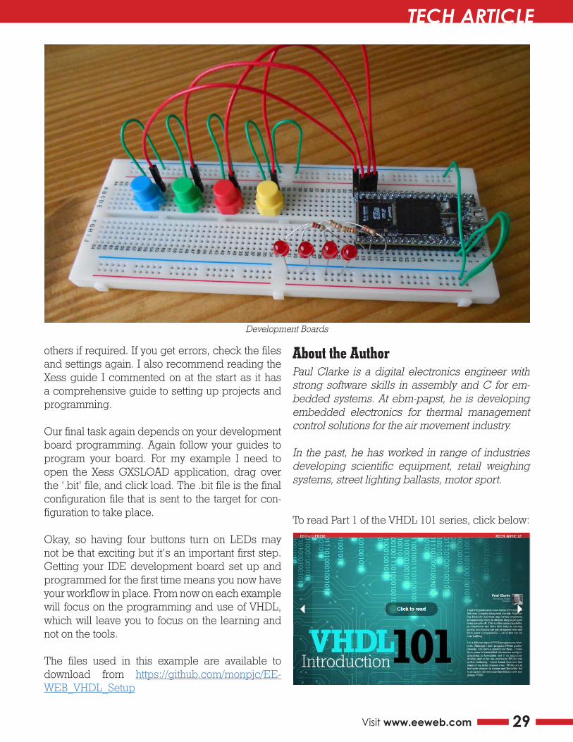
Development Boards
About the AuthorPaul Clarke is a digital electronics engineer with strong software skills in assembly and C for em-bedded systems. At ebm-papst, he is developing embedded electronics for thermal management control solutions for the air movement industry.
In the past, he has worked in range of industries developing scientific equipment, retail weighing systems, street lighting ballasts, motor sport.
To read Part 1 of the VHDL 101 series, click below: