26
Electrical Engineering Community Trishan Esram Advanced Power & Energy Systems EEWeb PULSE EEWeb.com Issue 23 December 6, 2011
| Date post: | 19-Feb-2016 |
| Category: |
Documents |
| Upload: | eeweb-magazines |
| View: | 222 times |
| Download: | 0 times |

Electrical Engineering Community
Trishan EsramAdvanced Power & Energy Systems
EEWeb
PULSE EEWeb.comIssue 23
December 6, 2011

Contact Us For Advertising Opportunities
www.eeweb.com/advertising
Electrical Engineering CommunityEEWeb
Digi-Key is an authorized distributor for all supplier partners. New products added daily. © 2011 Digi-Key Corporation, 701 Brooks Ave. South, Thief River Falls, MN 56701, USADigi-Key is an authorized distributor for all supplier partners. New products added daily.
www.digikey.com/techxchange
It’s all about connections.
The user-to-user forum is for everyone, from design engineers to hobbyists, to discuss technology, products, designs and more. Join the discussions that match your interest or offer your expertise to others.
Join the discussion now at:
discussions
hobbyists
engineers
industry experts
resourceslinks
technical documentswhite papers
reference designs
application notes
community
power
microcontroller
lighting
wireless
sensor
students

EEWeb | Electrical Engineering Community Visit www.eeweb.com 3
TABLE O
F CO
NTEN
TSTABLE OF CONTENTS
Trishan Esram 4Advanced Power and Energy Systems
Pacific Northwest Smart Grid 8Demonstration ProjectBY BATTELLE
Featured Products
The Rise of the Permanent Magnet 13MotorBY PAUL CLARKE WITH EBM-PAPST
How Do Solar Chargers Work? 17BY JEFF CRYSTAL WITH VOLTAIC
RTZ - Return to Zero Comic 25
Learn about a project that verifies the viability of smart grid technology and quantify smart grid costs and benefits.
Interview with Trishan Esram - Pacific Northwest National Laboratory
An in-depth look into solar chargers and how they function.
Clarke introduces Permanent Magnet or EC Motors and describes their rise in society.
12

EEWeb | Electrical Engineering Community Visit www.eeweb.com 4
INTERVIEWFEA
TURED IN
TERVIEW
Pacific Northwest National Laboratory
What has your journey in engineering been like so far?Shortly after graduating from high school in my home country Mauritius—a tropical paradise island in the southern Indian Ocean—I started pursuing my bachelor’s degree in electrical engineering at Northeastern University in Boston, Mass., in the fall of 1999. My interest in power electronics started during my senior year and brought me to the Power and Energy Systems group at the University of Illinois (U of I) at Urbana-Champaign, in 2003, for my graduate studies. At U of I, my focus shifted toward the design and application of power electronics to optimize the energy harvest from renewable energy sources and integrate them into the electric power grid. While completing my doctorate degree, I was part of a small team of engineers at SolarBridge Technologies, Inc., designing an innovative micro inverter for alternating-current photovoltaic modules.
Upon graduation from U of I, I joined the Pacific Northwest
National Laboratory, or PNNL, operated by Battelle, in Richland, Washington. I am now an integral member of the technical team working on the Pacific Northwest Smart Grid Demonstration Project, or PNW-SGDP, led by Battelle. The PNW-SGDP is the largest regional smart grid demonstration in the U.S., involving the Bonneville Power Administration, or BPA, 11 utility representatives, five technology
partners, and more than 60,000 metered customers across five Pacific Northwest states—Idaho, Montana, Oregon, Washington and Wyoming.
What is the most intriguing aspect of your current work?PNNL’s Electricity Infrastructure Operations Center in Richland, Washington, is probably the “coolest” part of the PNW-SGDP.
Trishan Esram - Advanced Power & Energy Systems; PNL
Trishan Esram

EEWeb | Electrical Engineering Community Visit www.eeweb.com 5
INTERVIEWFEA
TURED IN
TERVIEW
The EIOC, as it is called, is a unique R&D center, set up as an actual room, where grid operators can work and develop new tools to make the existing electric grid more efficient. The PNW-SGDP utilizes the EIOC not only as a control center, but also to collect, store, analyze and evaluate data that will be collected within the different utility territories before and during the two-year demonstration period.
What is a unique feature of your current project?As part of the PNW-SGDP, we are integrating a number of tools to create a unique signal called the transactive control signal. At any place and any time, the signal can communicate the price and availability of power to the assets that are part of the project, such as a smart thermostat, allowing those assets (or other end users) to make the best decision about energy use. The information we hope to glean from using this signal as part of the project will help more accurately quantify costs and benefits of a future power system and help us fully realize the capability of a variety of smart grid functionalities.
What are the goals of the Pacific Northwest Smart Grid Demonstration Project?One of the main goals is to quantify the costs and benefits of the different smart grid technologies that are being installed in our region. When the Department of Energy awarded Battelle this project with American Recovery and Reinvestment Act funding, the intention was to understand what is the business case for smart grid, and how
will different technologies work? They wanted to be able to inform a regional and national case for smart grid, with the ultimate goal of establishing a more efficient energy infrastructure. We would really like to make more of the energy we have now and meet the growing demands for the needs in the future, without having to build more power generation.
The team of engineers in the Advanced
Power and Energy Systems group at
PNNL will continue to develop more tools
that can improve the ability to provide
reliable, secure and clean power.
What are the primary operational objectives of the Pacific Northwest Smart Grid Demonstration Project?As far as the PNW-SGDP is concerned, the operational objectives, as supported by the utilities involved, are as follows:
• manage peak demand
• facilitate wind integration
• address constrained resources
• improve system reliability
• improve system efficiency
Who makes up the team working on the PNW-SGDP?A core team at Battelle’s Pacific Northwest Division is managing the project, which consists of the Bonneville Power Administration, 11 utilities in the Pacific Northwest and five technology participants.
What challenges do you foresee in our industry?For me, the biggest challenge is the development and production of reliable, robust, efficient and inexpensive energy storage systems that can be used to “firm” intermittent renewable energy sources like wind and solar. Only when such energy storage systems are available will utilities be less concerned about the reliability and stability issues caused by the intermittent renewable sources. And only then will the level of integration of renewable energy sources into the existing power grid start to increase and help to reduce our dependency on fossil fuels.
What is on your bookshelf?Among the books on my bookshelf, Elements of Power Electronics by Philip T. Krein, Feedback Control of Dynamic Systems by Gene F. Franklin et al., and Power System Stability and Control by Prabha Kundur are three textbooks that I find to be very handy and easy-to-read references.
What has been your favorite project?So far, my favorite project remains

EEWeb | Electrical Engineering Community Visit www.eeweb.com 6
INTERVIEWFEA
TURED IN
TERVIEW
the U of I’s participation in the U.S. Department of Energy’s 2007 Solar Decathlon, during which 20 teams of college and university students competed at the National Mall in Washington, D.C., for the most energy efficient and aesthetically appealing net-zero, stand-alone solar house. I was the electrical engineering team leader, working with more than 20 students to design and construct the PV, energy storage, and AC distribution systems of the house. What made this project even more memorable was the flawless collaboration
between the multidisciplinary teams and the wonderful guidance of the U of I’s faculty members.
Do you have any note-worthy engineering experiences?To have led and been part of the team that designed and assembled the complete code-compliant electrical system of the U of I’s Solar Decathlon house, without prior electrician training, and to be the first among the 20 teams to have had the electrical system up and converting free solar energy for the house on the National Mall.
What direction do you see your business heading in the next few years?The team of engineers in the Advanced Power and Energy Systems group at PNNL will continue to develop more tools that can improve the ability to provide reliable, secure, and clean power. ■
Join Today
www.eeweb.com/register
Electrical Engineering CommunityEEWeb

Avago Technologies new generation optocouplers, ACPL-x6xL series and ACNW261L, o� er signi� cant power e� ciency improvements for industrial communication interfaces. With 35 years of experience in digital optocoupler design, Avago delivers quality you can count on.
www.avagotech.com/optocouplers
Technology You Can Trust
Ultra Low Power Digital Optocouplers in Industrial Communication Interfaces90% less power than standard optocouplers40% lower power than alternative opto-isolators
To request a free evaluation board go to:
Controller Transceiver
OptocouplersACPL-M61L/064L/W61L/K64L
Bus L
ine
Key Features• Ultra low power
• High temperature and supply voltage range
• High noise immunity (35 kV/µs dynamic and static common mode rejection)
• Certifi ed for safe insulation (up to 1140 Vpeak continuous working voltage)

EEWeb | Electrical Engineering Community Visit www.eeweb.com 8
PROJECTFEA
TURED PRO
JECT
Pacific Northwest Smart Grid Demonstration ProjectThe Pacific Northwest Smart
Grid Demonstration project is a regional endeavor
funded by the Department of Energy under the American Recovery and Reinvestment Act of 2009. The goal is to verify the viability of smart grid technology and quantify smart grid costs and benefits. This information will help validate new smart grid business models at a scale that can be adapted and replicated nationally. With the 50 percent DOE matching funds, this project has a $178 million budget.
Smart grid can help meet increasing power demands, reduce greenhouse gas emissions, promote energy independence, enhance reliability and help improve national security. It is a system that uses technology to enhance power
delivery and use through intelligent two-way communication.
Power generators, suppliers and users are all part of the equation. With increased communication and information, smart grid can monitor activities in real time, exchange data about supply and demand and adjust power use to changing load requirements. Smart grid technology includes everything from interactive appliances in homes to substation automation and sensors on transmission lines.
The regional project, the largest smart grid demonstration project in the nation, is led by Battelle Memorial Institute’s Pacific Northwest Division. Participants include the Bonneville Power Administration, eleven utilities,
two universities and infrastructure providers. It includes 112 megawatts of responsive resources and will last for five years.
At the Heart of Our ProjectTransactive control, a smart grid technique using an incentive and feedback signal that helps coordi-nate smart grid resources, is the glue that binds the Pacific North-west Smart Grid Demonstration Project. This technological innovation can help optimize use of the grid and power resources, providing benefit to the region as a whole, utilities and end users alike.
Using transactive control can help eliminate the need to build costly thermal resources, reduce the region’s carbon footprint, smooth out peaks in electricity use, help
Written By Battelle
EEWeb | Electrical Engineering Community Visit www.eeweb.com 9
PROJECTFEA
TURED PRO
JECT
integrate intermittent renewable resources (like solar and wind) and help keep future costs from rising as quickly as they otherwise would.
Transactive Control SignalsIn technical terms: The Pacific Northwest Smart Grid Demonstra-tion Project is developing a new approach to managing resources throughout the electric power system. This technique, called transactive control, uses distributed communications to send a transac-tive incentive signal and receive a transactive feedback signal within the power system’s hierarchical node structure.
In human terms: The transactive control signals contain information about what power is available (and at what price) and what power is needed by end users. Two-way communication of this information — all the way from the source of electricity, such as dams or wind projects, to the home — allows intelligent devices and consumers to make smart energy use decisions thus benefiting the region, utilities, and consumers. These benefits include helping improve efficiency of the regions’ power system, cost effectiveness, enhanced reliability, as well as decrease the carbon footprint.
Transactive control is the centerpiece of the demonstration project. Its success, combined with the testing of utility-level smart grid assets, will help make a business case for smart grid. That will allow utilities in the region to make wise smart grid investments and create a more robust power system for years to come. If successful, it also can serve as a model for national implementation.
How does it work?The transactive control signal represents the monetary value of power in terms of dollars-per-megawatt-hour, at a given point in time and specific location, in an
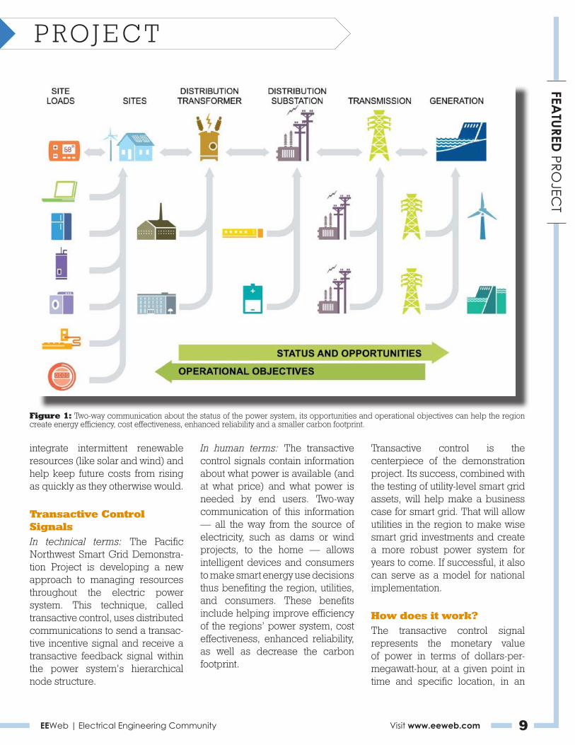
Figure 1: Two-way communication about the status of the power system, its opportunities and operational objectives can help the region create energy efficiency, cost effectiveness, enhanced reliability and a smaller carbon footprint.

EEWeb | Electrical Engineering Community Visit www.eeweb.com 10
PROJECTFEA
TURED PRO
JECT
electronic form. The signal moves through the system (see Figue 1), incentivizing the use and movement of power. It’s a forward-looking signal, meaning that it forecasts days ahead and is updated every five minutes.
Data for the signal originates with the power generators. From there it propagates downstream through the network, following the flow of power, and corresponding to physical locations in the electrical system called nodes. These nodes can be anything (from appliances to a customer meter or a substation) that can receive information and transmit it, either up or downstream, so that other assets on the system can respond appropriately.
At each node, a decision is made to increase the incentive signal value if less electric load is needed below that point, or decrease the incentive signal value if more load is needed.
Flowing in the other direction, starting with end-use points such as homes, information is accumulated and forwarded about expected energy use over the next day. In this way the transactive control system is a closed loop.
Generators see what the expected load will be and plan accordingly —end uses of electricity see what the expected price and availability will be and likewise plan their use. Over time, the incentive signal and the load signal converge, with planned supply of electricity matching planned use. In figure 1 on page 2, the incentive signal is shown as “operational objectives” and the load signal as “status and opportunities.”
What are the benefits?This two-way communication maximizes opportunities for the region to optimize the use of resources, such as renewable energy, and helps the system meet operational objectives, such as reliability. For example, if the wind is blowing and producing a lot of power in a particular locality or region, the transactive control system would make using that power locally a priority through pricing incentives.
Conversely, if a particular area were experiencing congestion on itstransmission system, a feedback signal from the nodes would help move power to other parts of the system to help prevent a blackout.
Utilities can use the signal to optimize their own resources, including reducing peak load, reducing phase imbalance on a transformer or preventing overloads on a transmission line. Eventually the incentive signal will let consumers make educated choices about how and when to use electricity, and even at what price.
Of the test cases in the demonstration project, 41 involve the transactive control signal.
Although the demonstration project will use simulated price incentives instead of actual changes in wholesale power prices, the structure of the project is intended to provide for a realistic scenario at a scale that can be applied regionally, and even to other parts of the nation. The transactive control system is slated to be up and running by September 2012.
The demonstration project also can shape national interoperability standards. This aspect is, in fact, one of the four main goals of the project.
Project-Level Infrastructure PartnersWho will bring the transactive control system to life and make sure it works? The demonstration has assembled an expert team of technical partners to help with system design, communication, computation, interoperability, cyber security, renewable energy integration and analysis.
Battelle’s Pacific Northwest Divi-sion, located in Richland, Wash-ington, is leading the project. This non-profit organization is responsi-ble for providing technical leader-ship, data management and overall project management. Battelle is responsible for the project’s allo-cation and expenditures, schedule and quality control. It is also putting together the cyber security plan in collaboration with the other part-ners.
The Bonneville Power Adminis-tration, a federal agency in the U.S. Department of Energy, represents the project-level transmission, gen-eration and renewable energy ob-jectives of the region and will link the project together from the power system point of view. BPA has pri-mary roles in business case de-velopment, outreach and external communications, system data input and design input.
Alstom Grid will define and calcu-late the simulated wholesale power price that will serve as the foun-
EEWeb | Electrical Engineering Community Visit www.eeweb.com 11
PROJECTFEA
TURED PRO
JECT
dation for the transactive control signal. To that end, it will provide operations software, and provide services that will enable real-time dynamic pricing and renewable energy management in the project.
IBM is building the infrastructure to disseminate the signal and inter-lace it with the responsive assets. Its contributing servers and soft-ware that will allow for effective streaming of data.
Netezza’s data storage appliance will provide processing speed and power to analyze and understand the project’s data.
QualityLogic will develop tools to test the transactive control system’s conformance to specifications and interoperability, and will perform testing to confirm that the signals are correctly communicated along the nodal hierarchy. QualityLogic co-leads the investigation and adoption of national smart grid standards into the control signal. Testing and standards influencing efforts undertaken by QualityLogic and other project participants will help establish the nodal transactive control technology as a national standard.
3TIER will serve as the weather-man of the project, forecasting wind and solar resource availabil-ity at hourly intervals, days ahead and at five-minute intervals within the hour. These forecasts will affect the region’s incentive signals to en-courage variable renewable energy consumption when and where the resources are available.
To find more information, please see http://www.pnwsmartgrid.org/.■
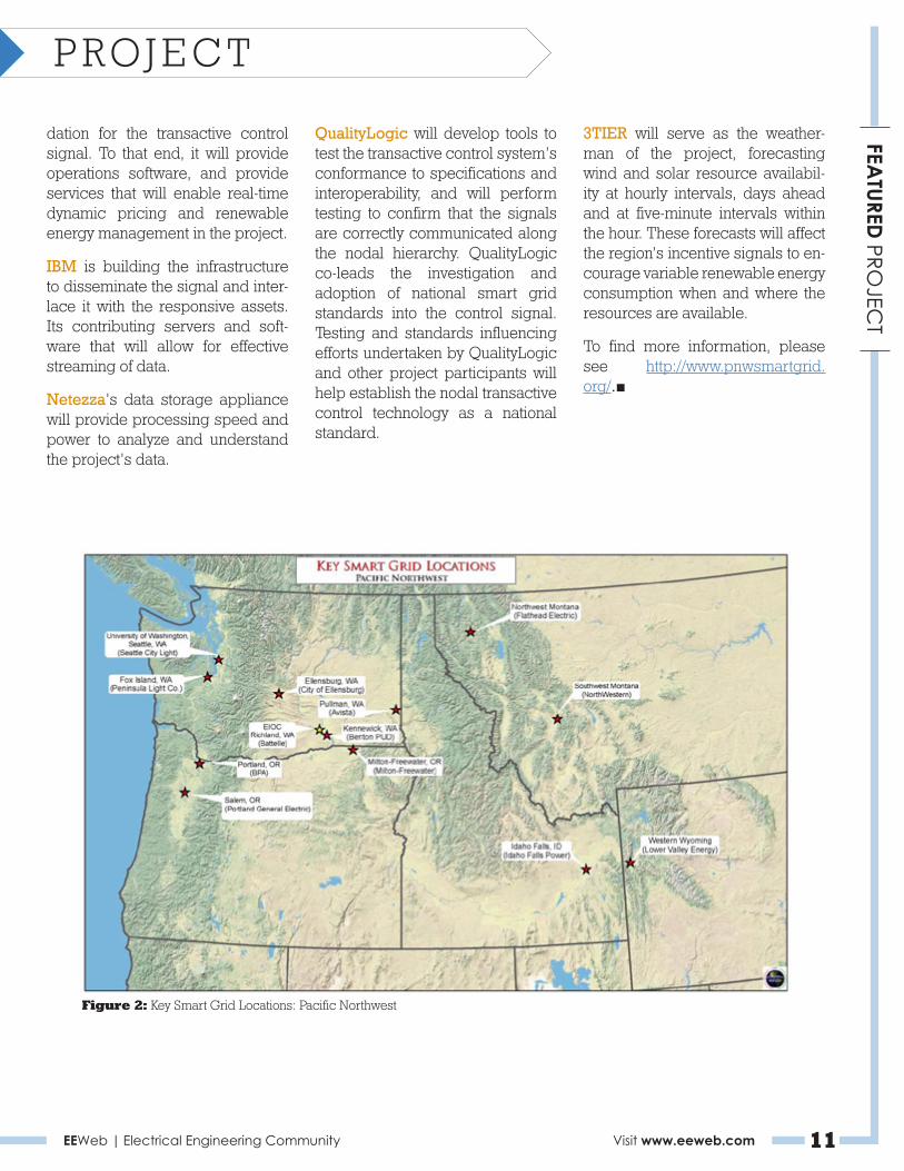
Figure 2: Key Smart Grid Locations: Pacific Northwest
EEWeb | Electrical Engineering Community Visit www.eeweb.com 12
FEATURED
PROD
UCTS
FEATURED PRODUCTS
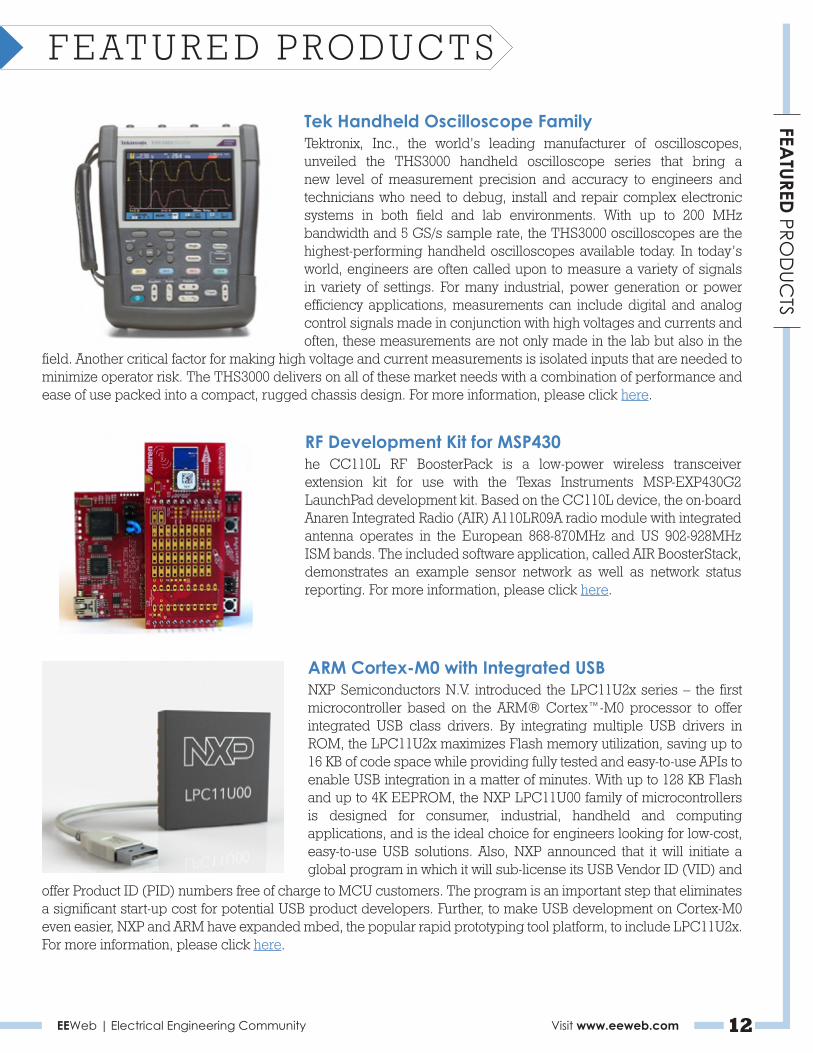
Tek Handheld Oscilloscope FamilyTektronix, Inc., the world’s leading manufacturer of oscilloscopes, unveiled the THS3000 handheld oscilloscope series that bring a new level of measurement precision and accuracy to engineers and technicians who need to debug, install and repair complex electronic systems in both field and lab environments. With up to 200 MHz bandwidth and 5 GS/s sample rate, the THS3000 oscilloscopes are the highest-performing handheld oscilloscopes available today. In today’s world, engineers are often called upon to measure a variety of signals in variety of settings. For many industrial, power generation or power efficiency applications, measurements can include digital and analog control signals made in conjunction with high voltages and currents and often, these measurements are not only made in the lab but also in the
field. Another critical factor for making high voltage and current measurements is isolated inputs that are needed to minimize operator risk. The THS3000 delivers on all of these market needs with a combination of performance and ease of use packed into a compact, rugged chassis design. For more information, please click here.
RF Development Kit for MSP430he CC110L RF BoosterPack is a low-power wireless transceiver extension kit for use with the Texas Instruments MSP-EXP430G2 LaunchPad development kit. Based on the CC110L device, the on-board Anaren Integrated Radio (AIR) A110LR09A radio module with integrated antenna operates in the European 868-870MHz and US 902-928MHz ISM bands. The included software application, called AIR BoosterStack, demonstrates an example sensor network as well as network status reporting. For more information, please click here.
offer Product ID (PID) numbers free of charge to MCU customers. The program is an important step that eliminates a significant start-up cost for potential USB product developers. Further, to make USB development on Cortex-M0 even easier, NXP and ARM have expanded mbed, the popular rapid prototyping tool platform, to include LPC11U2x.For more information, please click here.
ARM Cortex-M0 with Integrated USBNXP Semiconductors N.V. introduced the LPC11U2x series – the first microcontroller based on the ARM® Cortex™-M0 processor to offer integrated USB class drivers. By integrating multiple USB drivers in ROM, the LPC11U2x maximizes Flash memory utilization, saving up to 16 KB of code space while providing fully tested and easy-to-use APIs to enable USB integration in a matter of minutes. With up to 128 KB Flash and up to 4K EEPROM, the NXP LPC11U00 family of microcontrollers is designed for consumer, industrial, handheld and computing applications, and is the ideal choice for engineers looking for low-cost, easy-to-use USB solutions. Also, NXP announced that it will initiate a global program in which it will sub-license its USB Vendor ID (VID) and

EEWeb | Electrical Engineering Community Visit www.eeweb.com 13
Permanent Magnet Motor
the
RiseTheof
Paul ClarkeElectronics Design Engineer
Toward the end of July I read a post about how efficient AC induction motors are and how using them and reducing their speed will help us all to reduce the greenhouse effect, and save money and the planet. While this is not wrong, I was a little shocked that people still consider AC motors with such high regard when in fact there are much better solutions—solutions in the form of Permanent Magnet or EC Motors.
The article I read started by saying that the U.S. is introducing regulations requiring manufacturers to produce more energy-efficient appliances. However, it’s not just the U.S. enforcing this; the E.U. is also providing compliance regulations for motors. We are all very aware that being more efficient is not only better for the planet, but also for
our pockets. Induction motors have claims of being robust, reliable, low cost, and having a high efficiency of around 80 percent. It is important to keep in mind, though, that these motors can only run at full speed and hence, some form of speed control is required. This can come
in a number of forms where variable frequency drives come to the top of the list more often than not.
AC motors are inherently floored as they contain losses. At the core of motors are large windings that induce a magnetic field into the rotor. The rotor consists of a squirrel cage (for example) where the rotating electrical field generates a magnetic field that interacts with the main field generating the rotation. But the rotor will not follow the line frequency exactly, and this is called slip. Slip in a motor is a loss, and one that can’t be avoided in induction motors. Also, due to the motors design, we get losses in the laminations as well as the electrical copper losses in the windings, all of which are required to induce the magnetic field in the rotor.Figure 1: EC Motor Cross-Section.

EEWeb | Electrical Engineering Community Visit www.eeweb.com 14
TECHN
ICA
L ARTIC
LETECHNICAL ARTICLE
So ignoring induction motors to start with, let’s consider the benefits of speed control and frequency drives. There are lots of different manufacturers making these, each with their own efficiency figures. Frequency drives in my experience often refer to peak efficiency as the best results you will get. This will often be with a low frequency drive. This is because the switching devices, IGBTs or FETs, are most efficient at lower frequencies. However, electric motors contain lots of copper wires and when current is passed through them, they will move as a result of the magnetic field. The same can also happen to the laminations. When switched at
frequency cases, it causes the motor to hum like a speaker. This can be very annoying to anyone working around the motor, so controls engineers will use frequency drives at a higher frequency above the human hearing range. This, as you have predicated, will lower the efficiency of the frequency drive.
Below is an example of sound levels recorded between AC (Black Line) and PMM/EC fans (Green Line).
At ebm-papst we see lots of AC motors being used for fan applications, and it is here where we see other inefficiencies due to the load on a motor. Motors have peak efficiencies when running
Figure 2: Noise behavior for various control methods.
under optimum conditions. But if the speed is reduced, or they are used outside their optimum range, then the motor is less efficient. Running an induction motor slower is primarily achieved by creating more slip in the motor. Slip is already a loss in the motor and by inducing more, the motor becomes less efficient. Overall, what can look like a green product can be filled with inefficiencies in the final application.
Permanent Magnet Motors (PMM) already have a fixed and permanent magnetic field. This means that the energy you are using in an AC motor to generate the magnetic field in the rotor is not required in a PMM. This instantly gives PMMs an advantage as you are saving energy already. Just by running the motor at full speed you can see savings between motors. In this example we can see an AC motor with an input power of 110 Watts that is only delivering 50 Watts output. For the PMM in the same situation, the losses would only come to 17 Watts. Therefore, to generate the same 50 Watts output ,you would only need 67 Watts—a savings of 43 Watts.
These motors are, however, not like they used to be. Remember the Scalextric cars bombing around a track that would generate lots of RF noise or wear out the brushes? PMM are now typically brushless motors so this is no longer a problem. They have integrated electronics that allow for power and speed control into the windings.
In effect, the new electronics replace the outdated electronics that would be found in frequency converters. Although, in the case
70
60
50
40
30
2000
A - Phase-angle control, hum noise (300 Hz)
B - Frequency inverter whistle - motor and device resonance caused by frequency inverter-controlled motor
Noise behaviour for various control methods
Lp
A (
Sou
nd
Pre
ssu
re L
evel
)
V (Air Flow)
A
B
2000 2000 2000 2000 [m3/h]
[dBA]
AC with phase-angle controlAC with transformerAC with frequency inverterebm-papst EC

EEWeb | Electrical Engineering Community Visit www.eeweb.com 15
TECHN
ICA
L ARTIC
LETECHNICAL ARTICLE
of these motors, the AC supply is regulated and converted to an internal DC supply that is used to run the windings. This means that not only do you get the benefit of lowering the losses from PMM, but switching speeds are low and the windings generate no audible noise.
Having integrated electronics also allows for speed control. Thereforeinterfaces like 0-10 volts or some form of communication protocol can be used to speed control the motor, allowing PLC direct interfacing.
All new PMM and EC motors are far more efficient, as well as offering the same robustness, reliability, and life as that of an induction motor.
About the Author
Paul Clarke is a digital electronics engineer with strong software skills
in assembly and C for embedded systems. At ebm-papst, he develops embedded electronics for thermal management control solutions for the air movement industry. He is responsible for the entire development cycle, from working with customers on requirement specifications to circuit and PCB
design, developing the software, release of drawings, and production support. ■
Figure 3
Join Today
www.eeweb.com/register
Electrical Engineering CommunityEEWeb
Lamination Loss
Copper LossesAdditional Losses
Slip LossFrictional Loss
System Loss
Power Input 110WAC
Power Output 50W
Output
26W
26W
8W
~60W
EC
10W
7W
0W
17W
Heat Loss
air gap

High Efficiency 5V, 10A Buck RegulatorISL95210The ISL95210 is a high-efficiency step-down regulator that can deliver 10A of output current from a 5V input. The small 4mmx6mm QFN package and only four external components provide a very small total solution size. Low resistance internal MOSFETs deliver excellent efficiency and permit full power operation in a +90°C ambient without airflow.
The regulator operates from an input voltage of 2.97V to 5.5V, and provides a 0.6% accurate output voltage over the full operating temperature range. Intersil's patented R4™ control architecture provides exceptional transient response with no external compensation components. The output voltage may be programmed by an internal DAC or by an external resistor divider (see “Output Voltage Programming” on page 11 for more details).
Several digital control signals provide flexibility for users that want additional features. Switching frequency, switching mode, output voltage margining and daisy-chained power-good functions are all programmed by these pins. The ISL95210 also includes comprehensive internal protection for overvoltage, undervoltage, overcurrent and over-temperature conditions.
Related Literature• See AN1485, “ISL95210 10A Integrated FET Regulator
Evaluation Board Setup Procedure”
Features• 10A Continuous Output Current
• 2.97V to 5.5V Input Voltage Range
• Up to 95% Efficiency
• Full Power Operation in +90°C Ambient without Airflow
• R4™ Control Architecture Delivers Excellent Transient Response Without Compensation
• Pin Selectable Output Voltage Programming
• ±0.6% Output Voltage Accuracy Over Full Operating Temperature Range
• Programmable Enhanced Light-Load Efficiency Operation
• Output Voltage Margining and Power-good Monitor
• Small 6mmx4mm QFN Package
Applications• Point-of-Load Power Supplies
• Notebook Computer Power
• General Purpose Power Rail Generation
FIGURE 1. 10A DC/DC CONVERTER USING ONLY 4 EXTERNAL COMPONENTS
FIGURE 2. EFFICIENCY OF CIRCUIT SHOWN IN FIGURE 1 (INCLUDES INDUCTOR LOSSES)
VINPVCC
ENPG_IN
VSEL1FSET
MPCTMSELVSEL0FCCM T-PAD
VOUTVCC
AGND
PGND
PGOOD
PHASEVOUT = 1.2V
VIN = 5V
LOUT
420nH
COUT220µF
1µF
10µFCIN
CONTROLSIGNALS
POWER GOOD
VCC
+
ISL95210
LOUTCOUT
= MPC0740LR42C (NEC/TOKIN)= 2TPLF220M5 (SANYO)
FSW= 800kHz
100
95
90
85
80
75
70
65
60
55
500 1 2 3 4 5 6 7 8 9 10
IOUT (A)
EFFI
CIE
NC
Y (%
)
VIN = 5VVOUT = 1.2VFSW = 800kHz
November 17, 2011FN6938.3
Intersil (and design) is a registered trademark of Intersil Americas Inc. Copyright Intersil Americas Inc. 2011All Rights Reserved. All other trademarks mentioned are the property of their respective owners.
Get the Datasheet and Order Samples
http://www.intersil.com

EEWeb | Electrical Engineering Community Visit www.eeweb.com 17
Jeff CrystalElectronics Design Engineer
work?
SolarChargers
How do
Solar chargers use solar energy to power my electronics. Neat! How do they work?
Short answer: Sunlight hits solar panels → solar panels generate electricity → electricity flows into a battery → battery outputs clean power on demand to your device.
Long answer: We’ve created a five-part tutorial to take you through every stage of the process. Solar is obviously much less predictable than plugging into the grid, so we’ll be focusing both on specifications and what to expect in the real world. Bring along a multimeter and some parts from Radio Shack and you can get a pretty good idea of exactly how solar Chargers work.
Part 1: How do I measure Open Circuit Voltage and Short Circuit Current?
There are lots of great resources on how solar panels generate electricity, including Wikipedia. So we’re going to focus here on measuring the Open Circuit Voltage and Short Circuit Current of a solar panel in “perfect” and less-than-perfect conditions.
Every solar panel has a rated output that includes its Open Circuit Voltage (Voc), Peak Voltage (Vmp), Short Circuit Current (Isc), and Peak Current (Imp). The Peak Voltage and Short Circuit Current tell you the Voltage and Current of the panel before you connect it to anything (e.g., there is no load attached to the panel).
As a reminder, Voltage is represented by the symbol V for Volts and is a measure of the difference in electric potential energy between two points. Like air pressure, it flows from high to low. Current is a measure of the flow of charge through an area over time. We use the symbol I to stand for current and measure it in Amps, or simply A for short.
Let’s measure the output of a solar panel. You’ll need the following:
• Multimeter
• Solar Panel; we use our 2 Watt 6 Volt solar panel that uses Monocristalline cells, but you can use any panel you have lying around with any type of cells.

EEWeb | Electrical Engineering Community Visit www.eeweb.com 18
TECHN
ICA
L ARTIC
LETECHNICAL ARTICLE
• Sunlight; alternatively, you could use a couple of high-powered incandescent bulbs, but then you don’t get to spend the after-noon outside.
Measure Open Circuit Voltage
The black lead should be connected to COM and the red lead should be connected to V or VDC. Set the dial to 20, which means the Multimeter can measure up to 20 Volts.
Figure 1
Touch and hold the black lead to the “sleeve” of the solar panel connector or the black wire. Now touch and hold the red lead to the red wire or insert it into the “tip” of the solar panel connector. You’ll notice that
Figure 2
the Voltage moves around, but with the panel pointed at the sun, we saw between 6.89 and 6.98 Volts for Open Circuit Voltage. This is close to our specification of 7.0V Open Circuit Voltage on the 2 - Watt panel.
Measure Short Circuit Current
The black lead should be connected to COM and the red lead should be connected to the mA. Set the dial to an amount greater than what
Figure 3
you expect the current to be. In our case, we set it to 10.
We measured and got 0.33 Amps or 330 mAmps, which is close to our specification of 333mA.
Figure 4
Assess the impact of real-world conditions.
In the real world, it is not sunny all the time and our panels are not always pointed directly at the sun. So what happens when we move away from perfection?
Angle the panel so that it is facing the sun and record the voltage. Try slowly angling the panel away from the sun and note the changes in Voltage and current. Try shading parts of the panel and then the whole panel and note the changes in Voltage and current.
Here is what we recorded:
Figure 5
Figure 6: Thumb covering half a cell.
PositionDirectly Facing Sun
Angled 15 degrees
Angled 30 degrees
Angled 45 degrees
Angled 90 degrees
Angled 180 degrees
Finger on Corner (half of cell)
Fingers on Cell (full cell)
Faint Shadow
Close Shadows on Panel
6.82
6.81
6.78
6.73
6.07
5.89
6.79
6.74
6.78
5.78
0.33
0.32
0.32
0.29
0.06
0.03
0.2
0.04
0.25
0.03
Voltage (V) Current (mA)
As you can see, minor changes in angle don’t have a very significant impact on Voltage or current. However, once you get to about 45 degrees away from the sun, current

EEWeb | Electrical Engineering Community Visit www.eeweb.com 19
TECHN
ICA
L ARTIC
LETECHNICAL ARTICLE
starts to drop very sharply, meaning total power will also drop.
Similarly, light shadows on the panels decrease current by about 25 percent, but a heavy shadow over all or part of the panel drop panel output by 90 percent.
Move on to Part 2 of our Tutorial: How do I measure total output? In this tutorial we start connecting solar panels to loads and measuring how much power it is capable of generating.
Figure 7: Thumb covering whole cell.
Figure 8: Solar panel with heavy shade.
Part 2: How much power am I generating?
A solar panel does not do anything in isolation. It needs to be connected to something. That something is called a load. A load dissipates power and converts electrical energy to work.
We’re going to make a simple circuit where we connect a solar panel to a resistor. The resistance changes the behavior of the panel. The more resistance, the higher the Voltage but the lower the current. The lower the resistance, the lower the Voltage and higher the current. What we’re looking for is the point where the panel produces the most power.
In this tutorial, you’ll need the following:
• 2 solar panels
• multimeter
• breadboard
• a range of resistors
• Voltaic circuit box (optional)
1. Measure Voltage and current through multiple resistors:
If you haven’t already, strip the leads on your panel and connect them directly into the breadboard as shown below. Re-measure both the open circuit Voltage and short circuit current.
Then, connect a resistor to create a simple circuit and measure both the Voltage across the resistor and current through the resistor.
2. Repeat using a variety of resistors; create a table like below (we used eight different resistors).
3. Graph it!
Figure 9: Solar panel connected to beadboard .
Figure 10: Measure open circuit voltage.
Figure 11: Measure Voltage across resis-tor, then measure current through system.
EEWeb | Electrical Engineering Community Visit www.eeweb.com 20
TECHN
ICA
L ARTIC
LETECHNICAL ARTICLE
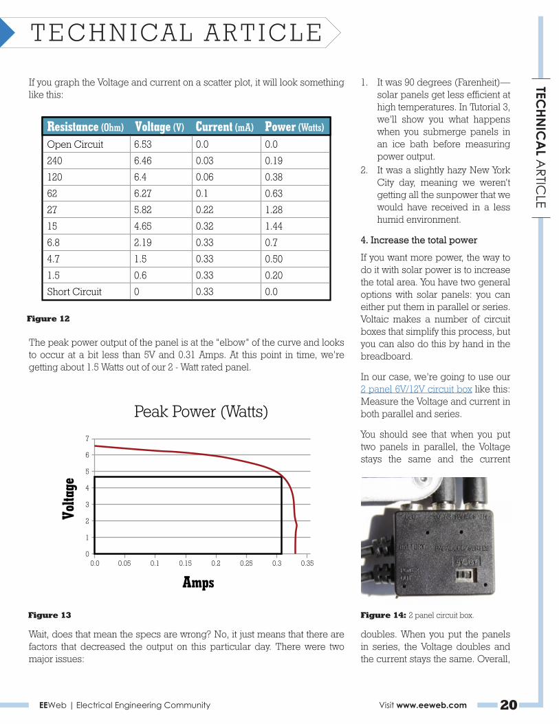
If you graph the Voltage and current on a scatter plot, it will look something like this:
The peak power output of the panel is at the “elbow” of the curve and looks to occur at a bit less than 5V and 0.31 Amps. At this point in time, we’re getting about 1.5 Watts out of our 2 - Watt rated panel.
Figure 12
Figure 13
1. It was 90 degrees (Farenheit)—solar panels get less efficient at high temperatures. In Tutorial 3, we’ll show you what happens when you submerge panels in an ice bath before measuring power output.
2. It was a slightly hazy New York City day, meaning we weren’t getting all the sunpower that we would have received in a less humid environment.
4. Increase the total power
If you want more power, the way to do it with solar power is to increase the total area. You have two general options with solar panels: you can either put them in parallel or series. Voltaic makes a number of circuit boxes that simplify this process, but you can also do this by hand in the breadboard.
In our case, we’re going to use our 2 panel 6V/12V circuit box like this: Measure the Voltage and current in both parallel and series.
You should see that when you put two panels in parallel, the Voltage stays the same and the current
Figure 14: 2 panel circuit box.
Wait, does that mean the specs are wrong? No, it just means that there are factors that decreased the output on this particular day. There were two major issues:
doubles. When you put the panels in series, the Voltage doubles and the current stays the same. Overall,
Resistance (Ohm)Open Circuit
240
120
62
27
15
6.8
4.7
1.5
Short Circuit
6.53
6.46
6.4
6.27
5.82
4.65
2.19
1.5
0.6
0
0.0
0.03
0.06
0.1
0.22
0.32
0.33
0.33
0.33
0.33
Voltage (V) Current (mA)0.0
0.19
0.38
0.63
1.28
1.44
0.7
0.50
0.20
0.0
Power (Watts)
Amps
Peak Power (Watts)
Volta
ge
7
6
5
4
3
2
1
00.0 0.05 0.1 0.15 0.2 0.25 0.3 0.35

EEWeb | Electrical Engineering Community Visit www.eeweb.com 21
TECHN
ICA
L ARTIC
LETECHNICAL ARTICLE
you get twice the power.
Figure 15: 2 panels in parallel – Voltage.
Figure 16: 2 panels in parallel – Current.
Figure 17: 2 panels in series – Voltage.
Figure 18: 2 panels in series – Current.
Note: the one-half Volt drop in Voltage is from the diode in the circuit box. Extra credit if you spotted that.
Keep on going to part 3 of the tutorial, where we connect panels to different batteries to measure power flow and estimate charge times.
Part 3: How (and why) do I store power?
Sunlight is inconsistent and often nonexistent (think nighttime), so storing power is important in many applications. In addition, many electronics are expecting a constant, specific Voltage with an ample power reserve. In this tutorial, we are going to show why you need power storage, how to measure power flow into two different types of batteries, and how to estimate how long it will take to charge a battery.
In the case of a solar charger, a battery stores power for when you need to charge your device. While it is possible to charge a phone directly from a solar panel, there isn’t always sun when your device
runs out of power. However, the following tutorial and math applies whether you’re charging a device directly or an intermediate battery.
Here’s what you’ll need:
• a solar panel—6 Volts or higher (we use our 2 Watt solar panel)
• solder-less breadboard• a few different NiMH or other
battery packs• diode (Schottky or other
rectifier)• multimeter
How long will it take to charge my batteries? It seems like a simple question, and we’ll show you how to answer it here. To do so we need to do the following:
a. measure the amount of power flowing into our batteries, andb. calculate the power capacity of our battery pack.
1. Measure Power into NiMh batteries
Connect solar panel to a pack of four NiMh AA2 and measure the Voltage and current at each step (where applicable). WARNING: DO NOT use Li-Ion batteries for this activity.
Connect a diode to the red wire of the solar panel in series. The diode will have a black marker (if glass) or a white marker (if plastic); this is the cathode or negative (-) terminal, and the other side is the anode or positive (+) terminal. The anode (+) should be connected to the positive wire of the solar panel. We use the diode to prevent the batteries from draining into the solar panels when there is not enough sunlight.

EEWeb | Electrical Engineering Community Visit www.eeweb.com 22
TECHN
ICA
L ARTIC
LETECHNICAL ARTICLE
Note: Matching the voltage of the panel to the voltage of your battery pack is critical. If the voltage from the panel is between two and three volts more than the battery pack voltage, then the pack will charge. If the voltage is significantly higher, you may damage your batteries. If it is equal to or less than the batteries, they will not charge.
Connect the battery pack to the panel and diode. The negative wire from the battery pack connects to the negative wire of the solar panel and the positive wire of the battery connects to the diode (the end opposite the positive wire of the battery).
Measure the current flowing into the battery pack: adjust your multimeter to measure current (10A), and connect it in series with the battery pack (red lead connects to cathode (-) of the diode and the black lead connects to the positive (+) wire of the battery pack). This current measurement will be the same whether you measure it before or after the diode, solar
Figure 19: Measure the voltage of the battery pack.
Figure 21
Figure 22 Figure 23: Measure the voltage of the panel with the battery load connected.
Figure 24: Measure the voltage of the battery pack with the solar panel and diode connected.
panel, or battery pack. We will use this to determine how much power is being transferred to our battery, and how much is lost in the circuit through the diode.
That’s it! Now here are the results that we got in Figure 26.
2. Calculate Capacity
We just measured how much power is flowing from the solar panels to the battery. The next ingredient we need to determine charge time is capacity of the battery pack.
Figure 25

EEWeb | Electrical Engineering Community Visit www.eeweb.com 23
TECHN
ICA
L ARTIC
LETECHNICAL ARTICLE
There are two types of capacity that we should be aware of. Batteries have a rating that tells us the charge capacity or how much electric charge they can store: the ampere-hour (Ah) or milliamp-hour (mAh) [note: 1000 mAh = 1 Ah]. However, it’s much easier to think about the power capacity or watt-hours. Power capacity can be calculated by multiplying the charge capacity of a cell by the voltage of the cell: amp-hours * volts = watt-hours or A * V = Wh (also: mA * V = mWh). We’re using 1.2V AA cells with a rate charge capacity of 2,700mAh. The power capacity for each of our 1.2V cells with 2,700mA would then be 3.24Wh (1.2V * 2,700mAh = 3,240mWh = 3.24Wh).
To find the total power capacity of our battery pack with four AA batteries, we simply multiply the watt-hour rating of one cell by the total number of cells. It doesn’t really matter whether we have all four in series, parallel, or two parallel sets of two in cells in series; our four AA batteries in series has a total power capacity of roughly 13Wh.
Now can we calculate how long it’ll take to charge? Yes!
Looking at our data we can finally estimate the time it will take to
Figure 26
charge: divide the total power capacity by the amount of power flowing into the cells. But there’s a catch! The average efficiency of NiMH batteries is 65 percent, meaning 35 percent of the power put into them is lost as heat. We must multiply the power being put into the cells by .65 (efficiency coefficient) to get a “real world” estimate of charge time for our battery pack, which looks like this:
.99W from our panel is flowing into the battery pack (yes, this factors in a .1W loss from the diode!)
.64W (.99W * .65 efficiency coefficient) is being stored by the battery.
If our batteries were being charged from a completely discharged state, we have the whole 12Wh capacity to charge.
12Wh / .64W = 20.25 hours
Assuming that the power transferred into the batteries would double if we added another panel in parallel with the first (a total of 4W), we can get that charge time down to about 10 hours.
This scenario perfectly illustrates why it is necessary to get the most out of your panels. We can do this in
at least two ways:
1. using more efficient batteries (i.e., lithium-ion)
2. using more efficient charge circuitry
3. Making the panels more efficient
Charge Smart Battery Packs
Our V11 USB Battery is a smart battery pack with electronics designed to optimize solar power to charge lithium-ion cells. This energy is provided at a regulated USB 5V standard up to 650mA. Additional electronics also offer protection features: thermal protection, short circuit protection, overcharge protection, and over discharge protection.
Connect the V11 to a 4W (2 × 2-Watt panel) and measure the voltage and current to calculate the power. What?! Only 2.27 Watts out of 4 Watts of panels? It’s still a little better than the estimated power transfer of only 2 watts directly charging the NiMH battery pack. Those panels have been hard at work all afternoon; let’s cool them down with a nice ice bath and see if that helps. Calculate charge times: The V11 has a rated
Figure 27
DescriptionAt panel - Unconnected
At battery - Unconnected
At panel - Connected
At battery - Connected
Drop of diode
6.44
5.12
5.79
5.22
0.53
-
-
0.19
0.19
0.19
Voltage (V) Current (A)-
-
1.1
0.99
-
Power (W)

EEWeb | Electrical Engineering Community Visit www.eeweb.com 24
TECHN
ICA
L ARTIC
LETECHNICAL ARTICLE
Figure 30: Let’s see that in a table.
power capacity of 11Wh. 2.27W was being transferred from the panels to the V11, and assuming that 75 percent of the power from the panels (under normal conditions, not iced) is stored in the battery, we can safely assume that 1.7W is used. The charge time for a
completely drained battery would then be 11Wh divided by 1.7W or about 6.5 hours. This is consistent with our field tests.
Coming up in part 4 is a look inside the circuitry that is designed to protect the battery.■
BeStar®
ACOUSTICS & SENSORS
Teamwork • Technology • Invention • Listen • Hear
PRODUCTSSpeakers
Buzzers
Piezo Elements
Back-up Alarms
Horns
Sirens/Bells
Beacons
Microphones
Sensors
INDUSTRIESAutomotive
Durables
Medical
Industrial
Mobile
Fire / Safety
Security
Consumer
Leisure
QS9000 • TS/ ISO16949 • ISO14001 • ISO13485 • ISO9001
bestartech.com | [email protected] | 520.439.9204
Preferred acoustic componentsupplier to OEMs worldwide
Figure 28
Figure 29: Let‘s see how it looks in a table.
Description4W Panel Setup to V11
4W Panel Setup to V11 (after ice bath)
4.54
4.71
0.5
0.58
Voltage (V) Current (A)2.27
2.73
Power (W)
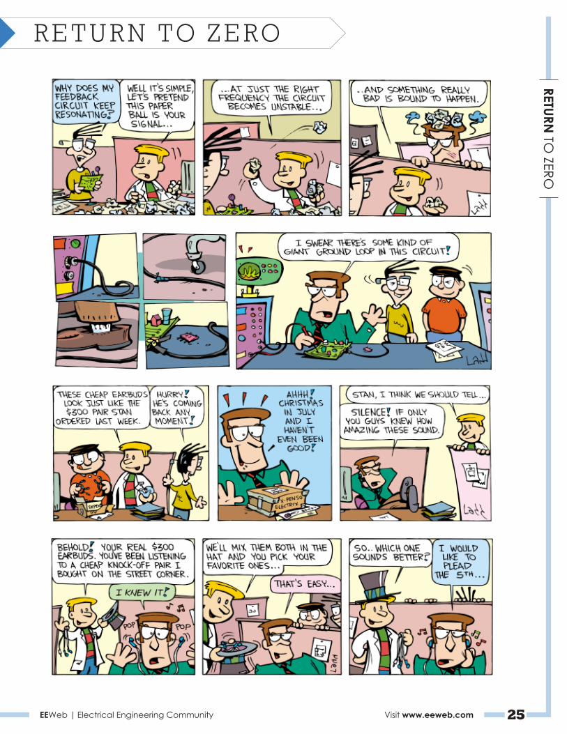
EEWeb | Electrical Engineering Community Visit www.eeweb.com 25
RETURN TO
ZERORETURN TO ZERO

EEWeb | Electrical Engineering Community Visit www.eeweb.com 26
RETURN TO
ZERORETURN TO ZERO
Contact Us For Advertising Opportunities
www.eeweb.com/advertising
Electrical Engineering CommunityEEWeb


