59
Field Measurement Methods [email protected] CAS on Magnets Novotel Brugge Centrum, Bruges, Belgium 16 - 25 June, 2009

Field Measurement [email protected]
CAS on Magnets
Novotel Brugge Centrum, Bruges, Belgium16 -
25 June, 2009

Overview
NMR/EPR, the golden standardFluxmeters, the workhorse for accelerators
fixed, moving, flipping, rotating coils and wiresHall generators and magneto-resistors, cheapOther fun methods
Fluxgate magnetometers, sensitiveSQUIDS, quantum sensitiveAtomic and SERF magnetometers, yet more sensitiveFaraday rotation, fast
Concluding remarks, and a design graph

NMR/EPR principlea particle with a spin and magnetic moment in an applied field precesses at a (Larmor) frequency f:
f = γ B
applied magnetic field
precession
spin magnetic moment
rotating component
longitudinal componentgyromagnetic
ratio

Gyromagnetic ratio
particle γ (MHz/T)
e- 28.025 x 10³
1H 42.576396(3)2H 6.535 2He 32.4326 13C 10.71 14N 3.08 19F 40.08 23Na 11.27 27Al 11.093 31P 17.25
1 GHz NMR
magnet ⇓
23.5 T
Electron Paramagnetic Resonance (EPR),
Electron Spin Resonance (ESR)
Nuclear Magnetic Resonance (NMR)
cryogenic probes

Resonance and coherence
a transverse RF pulse of frequency f induces resonance in the precession and coherence in Mt
RF pulse
coherence decay

Bloch, Purcell, 1946
500 mm3
sample
receiver
transmitter
Phys. Rev., 70, 460, 1946
Rabi, 1938

+
VNMR
probe
B0
RF
B
Osc.
S/H
∫ VCO
trigger
field modulation
frequency error signal
A DIY NMR magnetometer
0.1 ppm absolute accuracy achievable (0.1 Hz)

Field tracking
tracking is slow (Hz): maximum field variation tolerated for latching δB/B < 1 % s-1
field gradients blur signal: field homogeneity ∇B/B < 10 … 100 ppm/mm
gradient coils to measure inhomogeneous fields !
NMR signal
field modulation
error voltage
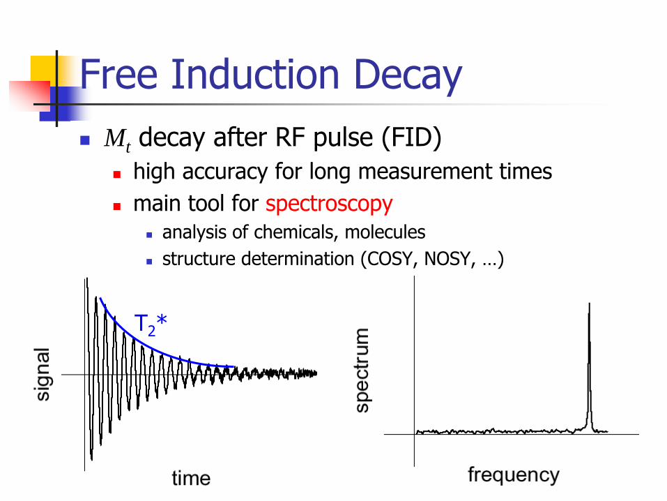
Free Induction DecayMt decay after RF pulse (FID)
high accuracy for long measurement timesmain tool for spectroscopy
analysis of chemicals, moleculesstructure determination (COSY, NOSY, …)
T2
*

ImagingMagnetic Resonance Imaging (MRI)
P. Lauterbur, 1973
z
B
f = γ B
z
fδf
δz courtesy of Philips
2000 Ig Nobel Prize winner, Annals of Improbable Researchl.W. Schultz, P. van Andel, I. Sabelis, E. MooyaartMagnetic resonance imaging of male and female genitals during coitus and female sexual arousalBritish Medical Journal, 319, 1596-1600, 1999.

Γ
S
B∫=S
dSBϕ
dtdV ϕ
−=
∫−=−end
start
t
tstartend dtVϕϕ
FluxmeterMagnetic flux:
Induction law:
κϕϕ startend
startend BB −=−
needs an integrator…
…
and coil calibration

Ann. Der Physik, 2, 209, 1853
magnetic inclination in Göttingen, also measured by:- Gauss- Humboldt- Forbes
…
that the determination of the inclination through the evaluation of the induction with the magnetometer are not worse
than the results obtained so far with the best inclinometers;
Inductions-Inclinatorium
few arcmin change observed over 50 years
… daß die durch Vermittlung der Induction mit dem Magnetometer an Präcision auch den durch die sorgfältigsten Beobachtungen mit den besten bisherigen Inclinatorien gewonnenen Resultaten nicht nachstehen;

Analog integrator (Miller)
R−
+
C
Vin
Vout
Rcoil
Rdischarge
∫∞−
−=t
inout dtVRC
V 1
shielding and control:-
leakage current-
ground current-
temperature coefficient-
dielectric absorption
triggering
simple, inexpensive, effectiveaccuracy limited by analog electronics
R+Rcoil

Digital integrator
−
+
Vin
Vref
Rcoil
VFCCNT 1
CNT 2μP
fref
n
∫∫ ==end
start
end
start
t
tinVFC
t
t
dtVKfdtn
digital output, no cumulative error, 10…100 ppm accuracy !VFC linearity and stability, counter resolution (Δt/(4 fref
) ppm)
voltage offset
parallel counters
instrumentation amplifier (Zinput
) Voltage to Frequency Converter
-Vref
…+Vref 0…2Vref 0…fref

Numerical integrator
Vin Rcoil
DVM
t
V
Vi
Δtitrigger
Vi
ti
Vi-1
ti ti-1
digital output, powerful numerical integration possibleprecise time required, dead-times, may need 2 DVM’s
digital approximation for numerical integration

Fast Digital Integrator
faster integrals (100 kHz), improved resolution (1 ppm)
+
Vin Rcoil
fref
ADC
FPGA
DSP
CLCK
C-PCI/PXI BUS -Vmax
…+Vmax 0…2Nbit
instrumentation amplifier (Zinput
)
Analog to Digital Converter
Field Programmable Gate Array
Digital Signal Processor

Point coils –
the Fluxball
winding axis
winding core
radius
winding density
W.F. Brown, J.H. Sweer,Rev. Sci. Instr., 16, 276, 1945
measure average field in a small volume (point-like)can be approximated by co-axial solenoids of proper R/H

Line and area coils
250
2250
0.5
Courtesy of J. Billan, CERN
integrated field over long lengthsrelevant for accelerators

Harmonic coils
+
+
+
+
−
− −
−
dBz/dx
dBz/dz
Morgan coil (B4
)Gradient coils
measure field gradients or higher order terms (bucking)high resolution through compensation of background field signal
G.M. Morgan, Proc. MT-4, 787-790, 1972

Fluxmeter zooFixed coil measurements
Static coils (dS/dt=0), the field change (dB/dt) induces the voltageProvides only a relative measurement (Bend-Bstart)The voltage offsets cannot be distinguished from physical signal
Γ
S
B
00123
dtdV ϕ
−= ∫=S
dSBϕ
Moving coil measurementsSteady field (dB/dt=0), the coil movement (dS/dt) induces the voltageRequires well controlled mechanics, simple movementsProvides and absolute measurement if:
initial Bstart=0 moving from far away into the magnet (zero-gauss chamber): moving coilusing symmetries Bend=-Bstart: flip coil, rotating coil
A voltage offsets can be distinguished from physical signal
Most flexible method in all its many variants, although…
“…This type of magnetometer is obsolete.”
http://en.wikipedia.org/wiki/Magnetometer

A rotating coil ???
…
no, actually this is a fixed coil with 800 turns and ≈
250 m2
surface that has been used to verify e.m. coupling of LEP and SPS
26”
Record wheel

Rotating snakes @ CERN
16 m
36
0.1 μT, 0.05 mrad resolution, 100 ppm accuracy

Complex formalismSC magnets for accelerators
2-D field (slender magnet), with components only in x and y and no component along zIgnore z and define the complex plane s = x + i y
Complex field function:
B is analytic in s and can be expanded in Taylor series (the series converges) inside a current-free disk:
xy iBB +=B
1
1
−∞
=∑ ⎟
⎟⎠
⎞⎜⎜⎝
⎛=+
n
n refnxy R
iBB sC nnn iAB +=C

Multipolescomplex multipole coefficients:
nnn iAB +=C
B1
≠0, normal dipole
A1
≠0, skew dipole
n=1 n=2
A2
≠0, skew quadrupole
B2
≠0, normal quadrupolen=3
1
1
−∞
=∑ ⎟
⎟⎠
⎞⎜⎜⎝
⎛=+
n
n refnxy R
iBB sC

Rotating coil in normal dipole
maxima and minima located at 0 and πcos(θ) waveform

Rotating coil in skew dipole
maxima and minima located at π/2 and 3/2 πflux de-phased by –π/2
with respect to normal dipole
sin(θ)
waveform

Rotating in normal quadrupole
maxima and minima located at 0, π/2, π
and 3/2 πflux variation twice faster than in a dipolecos(2 θ)
waveform

Rotating in skew quadrupole
maxima and minima located at 1/4 π, 3/4 π, 5/4 π
and 7/4 πflux de-phased by –π/4
with respect to normal quadrupole
sin(2 θ)
waveform
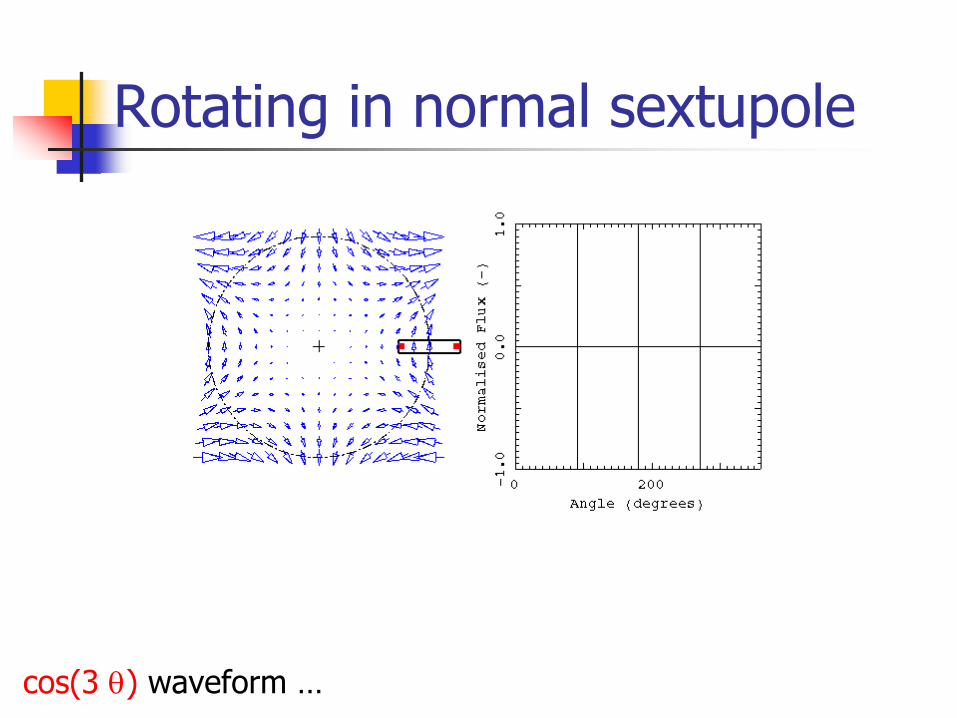
Rotating in normal sextupole
cos(3 θ)
waveform …

Fourier analysisn=2, B2
≠0
1 2 3-3 -2 -1
Ψn
n
n=1, A1
≠0
1 2 3-3 -2 -1
Ψn
n
n=1, B1
≠0
1 2 3-3 -2 -1
Ψn
n
Fourier transformed flux
coil calibration
and so on…
…by induction: Cn =˜ ϕ nκn

I
v
F
B
B cos( )
VH
+ + +
+ + + +
Hall generator principlethin slab of semiconducting material (AIIIBV):- InAs- InSb- GaAs
DC current
Lorentz force F = v x Btransverse DC
(Hall) voltage
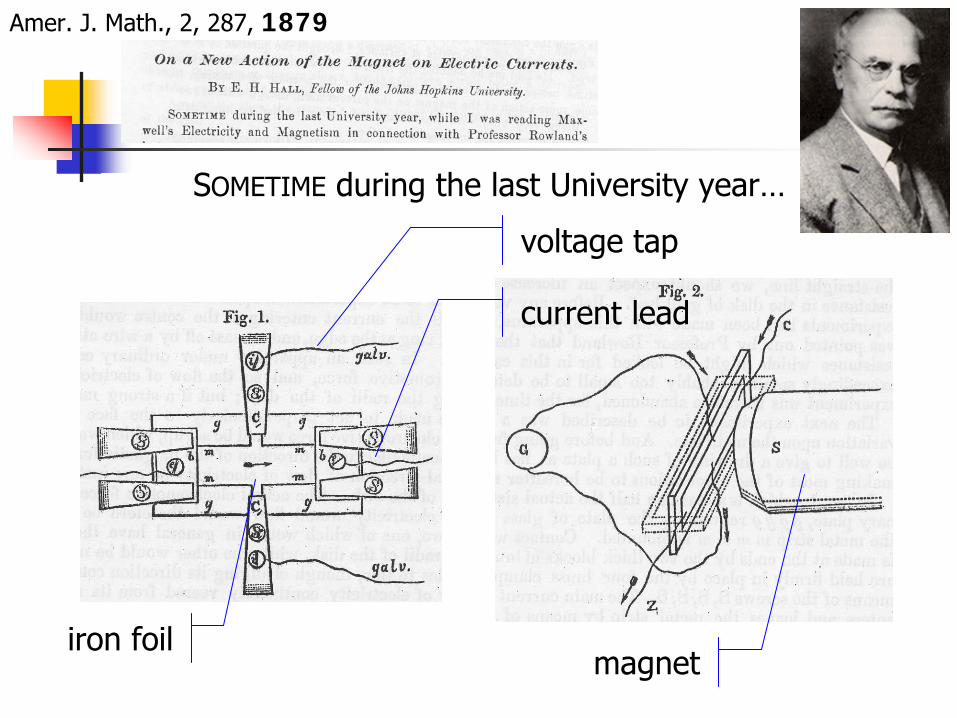
Amer. J. Math., 2, 287, 1879
iron foil
voltage tap
magnet
current lead
SOMETIME
during the last University year…

Hall coefficientHall voltage:
RH(B): material dependent Hall coefficienthigh mobility, low conductivity to have high RH
metals (low mobility)alloys (high resistivity causes heating)compromise choice: semiconductors
temperature dependence 100 to 1000 ppm/ºCG (B): geometry factor
equipotential lines deform under v x BOptimal design to compensate RH vs G
Cruciform design achieves 1 % linearity over wide B rangebetter definition of magnetic center
( )θcosIBGRV HH =
100 ppm accuracy feasible

Hall magnetometera Hall sensor is a 4-terminals device
do NOT connect outputs in series !!!
DC measurement can resolve 1…10 μTAC (lock-in) can resolve 0.1 μT
I= I0 sin(2πft), f = 10 Hz … 1 kHz
VHall DVM
I
DVM
−
+ VHall
Vout
DVM
I
+
−
Vout
DVM

magnetic field
ΔRH/R
H
Quantum Hall effectShubnikov-de Haas effect
oscillation in RH periodic function of 1/B
periodic oscillation of ΔRH
/RH
effect as much as 1 % on calibration coefficient
B > 2 T
4.2 K

Planar Hall effect( )ϕ2cos2BVV HPplanar =
Vplanar
is important when mapping 3-D fields
BI φ
Vplanar

Phil. Trans.,146, 736, 1856
B
ΔR/R
0

Magnetoresistors
B
I
VB
InSb slab
NiSb precipitates
two-terminal device, simple, inexpensivemodest sensitivity, non-linear, T effects (2500 ppm/ºC)bias field, compensated bridges, giant-magnetoresistance

Fluxgate (Peaking Strip)
B
excitation coil
bias coil
detection coil
+Bexcitation
-Bexcitation
J. M. Kelly, Magnetic Field Measurements with Peaking Strips, Rev. Sci. Inst., 22, 256, 1930

M
H
t
H
M
t
M1, M2
M1-M2
V
t
Fluxgate principle -
1
B
excitation coil
bias coil
detection coil

Fluxgate principle -
2
B
excitation coil
bias coil
detection coil
M
H
t
HH0
V
t
M
t
M1
M1-M2
M2
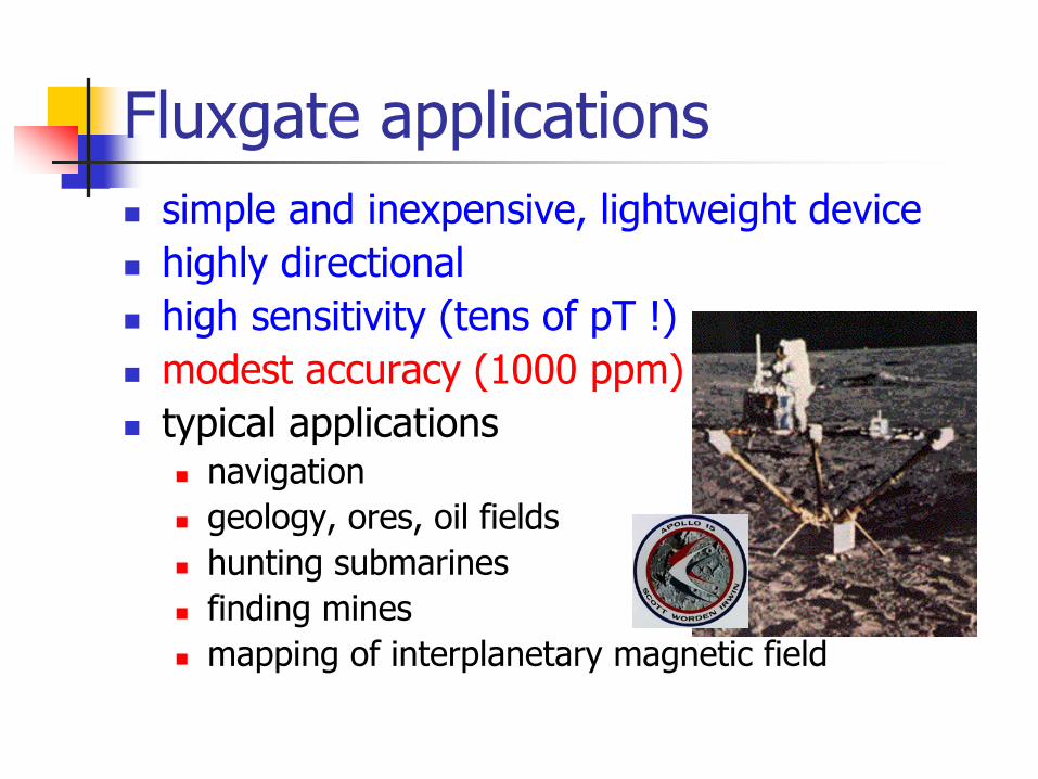
Fluxgate applicationssimple and inexpensive, lightweight devicehighly directionalhigh sensitivity (tens of pT !)modest accuracy (1000 ppm)typical applications
navigationgeology, ores, oil fieldshunting submarinesfinding minesmapping of interplanetary magnetic field

A special fluxgate: the DCCT
excitation coil
bias coil
detection coil
B
I
best known device for high current (relevant for SC magnets)1 ppm possible at 10 kA (10 mA)

SQUID principles –
1
change δ of phase of wave-function for paired electrons along Γ depends on magnetic flux ϕ:
flux quantization: δ = 2π n0
2ϕϕπδ =
path Γ
around a normal conducting region
superconductor
quantum fluxoid (2 x 10-15
Wb)
0ϕϕ n=
A. Abrikosov

the wave-function can tunnel through a normal-conducting (Josephson) junction the maximum supercurrent depends on δ:
SQUID principles –
2
( )δsincII =
superconductor
normal conductorδ
superconductorB. Josephson

V
Ibias
δ1,I1B
δ2,I2
The SQUIDmaximum supercurrent:
phase relation:
SQUID critical current
⎟⎟⎠
⎞⎜⎜⎝
⎛=
0
cos2ϕϕπcII
021 2
ϕϕπδδδ =−+
( ) ( )[ ]21 sinsin δδ += cII
Josephson junction
SC ring

SQUID operationSQUID voltage periodic in ϕ0
flux change Δϕ from ΔV, compute ΔB using κbias current
sensitivity few pT for bare SQUID, 1 fT with input transformerrange limited by FB, accuracy limited by calibration of surface
V
Ibias
δ1,I1B
δ2,I2

SQUID Magnetometry
151 SQUID channelshelmet
magnetoencefalogram
cortical activation of the primary and secondary somatosensory cortex during left median nerve simulation measured by MEG and fMRI…
HTS
LTS

The frontier of magnetometry
Alkali atoms (Rb, Cs) have unpaired electrons whose spin precesses with magnetic field (as protons)The interaction with field can be detected as follows:
An alkali metal vapor is prepared in a cellA first laser (the pump) aligns the spins to create coherence (as the RF pulse in NMR techniques)A second laser (the probe) detects resonance, which can be seen, e.g., as a shift in an interference pattern
Excellent device for miniaturizationSandia National Laboratories

A digression on spectra
The gross structure of the spectral line of atoms (energy level), are split in:
A fine structure (due to interaction of magnetic moment of electron spin and orbital angular momentum)
A hyperfinestructure, due to interaction of nucleus magnetic moment with internal magnetic/electric fields in the atom
E
794 nm377 THz
52P1/2
52S1/287
Rb
D1
line
6.83 GHz
The hyperfine structure further
splits in a magnetic field (Zeeman effect) proportionally to B
F=2
F=1
m=2m=1m=0m=-1m=-2
hΔν
≈
μgB
P. Zeeman
finehyperfine
Zeeman

Atomic magnetometer DIY
Set a laser on a given absorption line (e.g. D1 of 87Rb, 794 nm)AM the laser with a VCO to create two sidebands corresponding to the hyperfine structure (central f = 3.42 GHz)Modulate the VCO (by ± 3 MHz) to detect the resonances from the split hyperfine levelsCompute the difference of frequency between two resonances, which is proportional to the magnetic field:
hΔν
≈
μgBNIST
Princeton University
sensitivity in the range of tens of fTrange limited to 1 mT at most, accuracy not established so far

SERF atomic magnetometersSpin Exchange collisions preserve total momentum but cause single spins to change, scrambling the hyperfine structureThe precession of atoms in the vapor loses quickly coherence, the resolution of the resonance is limited
At low B and high gas density, collisions happen quicker than the precession time of the atoms. On average the hyperfine states are stable, the Spin Exchange is Relaxation FreeThe resonance is measured with improved resolution !
J.C. Allred, R.N Lyman, T.W. Kornack, M.V. Romalis, High-Sensitivity Atomic Magnetometer Unaffected by Spin-Exchange Relaxation, Phys Rev Lett 89, 130801, 2002

Premium sensitivity !Best quoted sensitivity is 200 aT/√Hz !
0.2 x 10⁻¹⁵ T at 1 Hz
A new world of possibilities
Magnetoencelography,Magnetocardiography of in fetal hearts,Earth field NMR …
a Tricorder ?!?
Example: NMR signal from water on chip

850 T pulsed field at LANL
material properties at high magnetic
fields (8 to 10 MG)
a shot …
imploding flux compression generator (VNIIEF design)

850 T shot at LANL
experimenttime
implosion and
flux compression
sample destroyed
how do you measure this ???

Faraday effect
material v (rad / T m)
fused quartz 4
flint glass 110
benzene 9
rotation angle
Verdet constant
field strength
lengthLBv=θ
rotation of light polarization in a media in a magnetic field
detector
laser
polarizer
sample
analizermagnet
fast, e.m. compatible at high electric fieldsmodest accuracy (1 %)
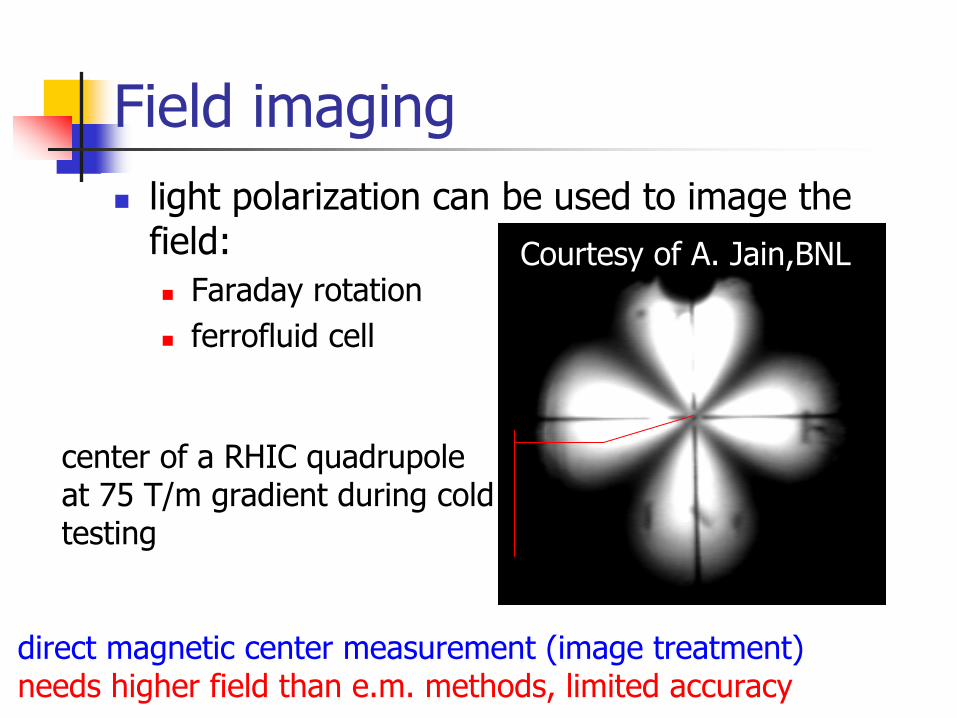
Field imaginglight polarization can be used to image the field:
Faraday rotationferrofluid cell
direct magnetic center measurement (image treatment)needs higher field than e.m. methods, limited accuracy
center of a RHIC quadrupole at 75 T/m gradient during cold testing
Courtesy of A. Jain,BNL

Performance summary

Conclusionsthe art of magnetic measurements cannot be made into a science
at least I have given up…methods and instruments exist, don’t try to make them yourself, use them if you can
as for italian cuisine let Mom do it……or buy a good cooking book before you start
where can I find out more ?CAS on MM, MT, PAC, EPAC(NIM) uNclear Instruments and Methods


