- This service manual is designed to help you to repair and maintain the EF-35 in order to keep it in good operating condition.Please read and understand the instructions in this service manual before performing any repair or maintenance.
- Horizon International Inc. shall not be liable for incidental or consequential damages resulting from: improper or inadequatemaintenance by the customer; unauthorized modification or misuse; or operation outside of the environmental specificationsfor the product.
- Horizon International Inc. follows a policy of continuing improvement in design and performance of the product. Therefore,the product design and specifications are subject to change without prior notice and without our legal obligation.
- All rights are reserved. No part of the manual may be photocopied, reproduced or translated to another language without theprior written consent of Horizon International Inc.
FOREWORD
Paper Folder
Model EF-35
II
Safety Precautions- Please read and understand all safety instructions with include the terms WARNING, and CAUTION. If these safety
instructions are ignored, personal injury may result.
- The repair, maintenance and safety instructions in this manual are valid only when the repair or maintenance work is performedaccording to the procedures described in this manual.
- The term WARNING indicates a potentially hazardous situation which, if not avoided, could result in death or serious injury.
- The term CAUTION indicates a potentially hazardous situation which, if not avoided, may result in damage on machines. It mayalso be used to alert against unsafe practices.
- Horizon International Inc. cannot anticipate every possible situation that might involve a potential hazard. The instructions in thismanual and the warning labels on the machine are therefore not all-inclusive.
- All equipment shall be locked out or tagged out to protect against accidental or inadvertent operation when such operation, repairor maintenance could cause injury to personnel. Do not attempt to operate any switch, valve, or other energy isolating devicewhen it has been locked or tagged out.
- Some of the drawings in this manual show the machine uncovered for explanations of details inside the machine.
III
1. Turn off power switch and pull out the plug for precautionexcept in case of neccesity before parts replacement or othermaintenance operations.
2. Mind rotating parts such as belt and pulley or electric cableswhen operating with covers removed.
3. A single operator must operate yourself only. This manualsupposes operations by a single operator.
4. Caution that other persons do not touch the machine duringyour service operations.
5. When turning on power switch again, wait for a dozen ofseconds after turning off.
6. When replacing parts, use parts shown in parts book exceptwhen the same functions can be found among commercialparts.
Service Operation Precaution
IV
Handling Precautions for P.C.Board and ROM
P.C.Board and ROM can be damaged by humanly imperceptible static electricity.Handle P.C.Board and ROM with following care.
Keep P.C.Board in a shield bag.
P.C.BoardShield Bag
Put the ROM on a conductive sponge and keep in a shield bag.
Shield Bag
Conductive Sponge
Do not put P.C.Board and ROM on the machine, especially on the acrylic cover. (No problem on the conductive plate.)
And keep the P.C.Board and ROM away from the insulators.Insulators: Plastic, form polystyrene,
chemical fiber fabric, dry paper, etc.
Acrylic Cover
When replacing the P.C.Board and ROM, or setting the dip switches and volumes on the P.C.Board, wear a wrist strap, and connect the clip to the machine frame (not painted surface).
BRN-g=The description "g" in cable color means the gray band tying the connector.RED-BLU=The description means that the wire is blue matrix with red stripe.
Abbr.ACBKCLCONCWCCWDC
DescriptionAlternating CurrentBrakeClutchConnectorClockwiseCounterclockwiseDirect Current
Abbr.DSWF.GJSWMSPBRYSSR
DescriptionDip SwitchFrame GroundJumper SwitchMicroswitchParts BookRelaySolid State Relay
Abbr.VRSigS/N
DescriptionVolumeSignalSerial Number (of machines)
3. Other Symbols
Abbr.SxxTxxUxxXxxYxxZxxWxx
VI
CONTENTSFOREWORD ........................................................................ I
Important Information ........................................................ I
Service Operation Precaution ............................................. III
Handling Precautions for P.C.Board and ROM ............... IV
Description of Abbreviations in This Manual ................... V
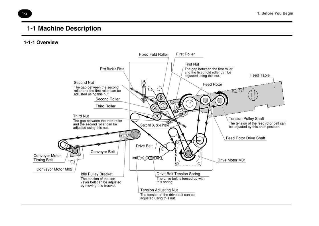
First NutThe gap between the first rollerand the fixed fold roller can beadjusted using this nut.
Feed Rotor
Feed Table
Tension Pulley ShaftThe tension of the feed rotor belt canbe adjusted by this shaft position.
Feed Rotor Drive Shaft
Drive Motor M01
Drive Belt Tension SpringThe drive belt is tensed up withthis spring.
Tension Adjusting NutThe tension of the drive belt can beadjusted using this nut.
Idle Pulley BracketThe tension of the con-veyor belt can be adjustedby moving this bracket.
Conveyor Motor M02
Conveyor MotorTiming Belt
Conveyor Belt
Drive Belt
Second Buckle Plate
First Buckle Plate
Second NutThe gap between the secondroller and the first roller can beadjusted using this nut.
Third NutThe gap between the third rollerand the second roller can beadjusted using this nut.
1. Before You Begin1-3
1-1 Machine Description
1-1-2 Control Panel (1)
34
34
1-1 Machine Description
Pause LEDThis LED lights while the machine ispaused, and also after a preset stop.
Feed Rotor Vacuum LEDThis LED lights while the feed rotor isproviding vacuum to sheet, and blinks whenthe continuous folding mode is selected.
Feed Sensor LEDThis LED lights each time a sheet passesthrough the feed section.
Feed Interval KnobThis knob is used to adjust the feed interval.
Vacuum Time KnobThis knob is used to adjust the vacuum time forthe feed rotor. When the knob is turned all theway to the right, the LED blinks and the feedrotor provides vacuum continuously.
Pause Time KnobThis knob is used to adjust the pause timebetween one batch of sheets and the nextbatch when the preset pause mode is selected.
Test Feed ButtonWhen this button is pressed while the motor isrunning, one sheet will be fed.
Roller/ Feed Start ButtonThis button is used to start feeding the sheets.Press this button once to start the motor, theroller, delivery conveyor, and the pump. Pressthis button again to start the feeding operation.
Roller/Feed Stop ButtonWhen this button is pressed once, the ma-chine stops feeding the sheets. Press thisbutton again to stop the motor, the roller,delivery conveyor and the pump.
Pump SwitchWhen switched on in motor running, theair blow into feed table.
Fold Speed KnobThis knob is used to adjust the rotatingspeed of the fold rollers.When the knob is turned all the way tothe left, the fold rollers might stoprotating.
Conveyor Speed Adjusting KnobThis knob is used to adjust the conveyorbelt speed. When the knob is turned allthe way to the left, the delivery conveyorbelts might stop rotating.
Conveyor SwitchThis switch is used to change the operat-ing mode of the conveyor.When is selected, the conveyoroperates continuously.When is selected, the conveyoroperates only after a sheet has passedthrough the feed sensor, and during thepause time.
1. Before You Begin1-4
1-1 Machine Description
1-1-2 Control Panel (2)
34
34
When the continuous folding mode is selected, the presetstop lamp and the pause mode lamp are turned off.
Total CounterThis indicates the total number of foldedsheets.
Total Counter Clear ButtonThe total counter can be reset using this button.
Preset CounterThis indicates the number of sheets to be foldedin preset stop mode or preset pause mode.
Preset Number Save ButtonThis button is used to save the preset number. The presetnumber can be viewed again by pressing this button even ifthe machine has stopped during the folding operationbecause it reached the preset stop number.
Preset /Number Set ButtonThese button are used to set the preset number. Thebuttons set the units, tens, hundreds, and thousandsdigit from the right respectively.Each number can be changed by pressing thecorrect button.
Mode Select ButtonThis button is used to change the mode forcontinuous folding, preset stop, and the presetpause counter.
1. Before You Begin1-5
1-2 Other Information
The angle of the feed table
Up to S/N008899Installed by inclining about 10 degrees upward to
the sheet feeding direction.
S/N009001-014899Installed on the level.
10
~S/N008899
S/N009001-014899
1-2 Other Information
The angle of the feed table is changed tothe level to feed the thin sheets stably.
1. Before You Begin1-6
This page is intentionally left blank.
2. Troubleshooting2-1
2. Troubleshooting
2. Troubleshooting2-2
2-1 The Sheet is not Fed (Although Feed Rotor Rotates)
First Check
- The gap between the gate plate and thefeed rotor is too narrow.
- The vacuum time is too short.
- Too many sheets are loaded.
- The feed guides are set too tight.
- The vacuum position of the feed rotor is notcorrect.
- The sheets are not separated correctly.
- The blower air is too weak.
If the pump filter is clean, make the air pressurestronger using the regulator on the blower. Even ifthe blower air is still weak after adjusting the airpressure, check that the blower air hose isconnected tightly using the hose clamp.
- The vacuum of the feed rotor is too weak.
If the pump filter is clean, make the vacuumstronger using the regulator on the vacuum pump.Even if the vacuum is still weak after adjusting thevacuum, check that the vacuum hose is connectedtightly using the hose clamp.
The blower and vacuum pump do notoperate.
- Check if the pump switch is turned on.
- Check if the pump connector X01 is
plugged in the machine. (Fig.1)
- Check if the pump circuit breaker Q20 is
tripped. (Fig.1)If the circuit breaker is tripped again, check if the
filter element of the blower and vacuum pump is
clogged, or the blower and vacuum pump is
overloaded.
If all of the outlets (five cocks) are closedcompletely, or closed almost, the blowerand the vacuum pump is overloaded.Release the air from the unused outlet.
Also, check if the electrical leak occurs on the
wiring between the Q20 and M03 (Fig.1)
- Check if the wiring between the power
switch S01 and the pump M03 is correct.
(Fig.2)
- When the start button is pressed, check if
the pump contactor K20 is turned on.
(Fig.1)When K20 is not turned on, if there is no defect
in the wiring between the pump contactor K20,
terminal A1, A2 and the Control P.C.B, CON 3,
Pin 9, 10, replace the contactor and the control
P.C.B in order.
- Check if the wiring between the pump
switch S14 and the Control P.C.B, CON 3
is correct. (Fig.2)
- When the pump switch is turned on, the
circuit is closed.
2. Troubleshooting2-3
2-1 The Sheet is not Fed (Although Feed Rotor Rotates)
Fig.1
EF-35
PAPER FOLDER
PAPER FOLDERQ20
K20
X01
- After pressing the start button and rotating
the feed rotor, press the start button or
the test button again. The sheet starts
being fed and the feed rotor vacuum LED
lights up.
If the suction air valve does not work, check
the followings.
- When the suction air valve works, check if
the feed rotor vacuum LED on the control
panel lights up. (L2 in section 6-2)If it lights up, check the wiring between the
Control P.C.B, CON 3 and the feed rotor Y01.
( 6-3 24VDC Wiring Diagram)
If there is no defect in the wiring, replace the
suction air valve and the control P.C.B in order.
If it does not light up, check if the input signal of
the start button is input into the P.C.B (L4 in
section 6-2). If there is no problem in the input
signal of the start button, replace the P.C.B.
2-1 The Sheet is not Fed (Although Feed Rotor Rotates)
2. Troubleshooting2-4
Fig.2
First Check
- The roller speed setting is too slow.
Adjust the roller speed using the fold speed knob.
The circuit breaker Q10 is tripped.
- If it is tripped again, check if the roller
motor is overloaded. And check if the
electrical leak occurs in the wirings from
the circuit breaker Q10 to the followed
wiring.
The motor driver (U01) is normal. (Fig.2)
- Check if the alarm LED (red) of the main
motor driver (U01) lights up.If it lights up, check the followings.
1. The motor is overloaded.
2. The input wiring is connected with the driver.
And the input voltage is 100V+/-10V.
3. The wiring to the main motor (M01) is OK.
- Check if the power LED (green) of the
main motor driver (U01) lights up.If it does not light up, check if the input wiring is
connected with the driver.
2-1 The Sheet is not Fed (Because Feed Rotor does not Rotate)
BLK
BLK
WHT
WHTRED
GRNREDBLKWHT
RED
GR
N
GR
N
BLK
BLK
BLK
BLK
WH
TW
HT
BLK
WH
T
BLKFG FG
BLK
WHT
WH
T
WH
T
WHT
BLK
GRN
AC100-115V~
SPEED POWER
ALARM
EXT-INT
S.S.
S.D.
BRUSHLESS DC MOTORDRIVER FBLD120AW
MO
TOR
I/O
VEXTA
S01Power Switch
X01Connector
Q20Pump Breaker
K20Pump Contactor
X03Terminal Board
Pump
Main Motor
Power Lamp
Alarm Lamp
M03
2
29
32
2 4 6 14
1 2 3
A1
A2
7643E
7643E
S14Pump Switch
CON3
BR
NR
ED
RE
DW
HT
9 10 11 12
1 3 5
2 4 6
QPW-589Control P.C. Board
L
N
NC
FG
1
2
3
4
5
6
7
8
9
10
11
12
M01
U01Main Motor Driver
2. Troubleshooting2-5
2-1 The Sheet is not Fed (Because Feed Rotor does not Rotate)
Belt
Tension Roller
Feed Rotor Belt
Reduction Pulley
M01
Feed Rotor Section
Pulley
2-1 The Sheet is not Fed (Because Feed Rotor does not Rotate)
The drive mechanism of the feed rotor isnormal. Check the followings. (Fig.3)
- Check if the belts slip on the pulley.Even If the belts are cleaned up and they still
slip, replace them.
- Check if the reduction pulley rotates
smoothly.
- Check if the pulley of the feed table is
fixed with the shaft tightly.
- Check if the feed rotor belts slip on the
feed rotor.Even If the belts are cleaned up and they still
slip, adjust the belt tension. ( “4-6
Replacing the Feed Rotor Belt and Adjusting the
Belt Tension”)
- Check if the feed rotor rotates smoothly.Remove the feed rotor belt and check the feed
rotor.
Fig.3
2. Troubleshooting2-6
First Check
- The sheets are curled.
- The buckle plate is not set correctly.
- If the sheet does not enter the first buckle,the gap between the buckle plate and thefold roller is too wide. (Fig.1)
- If the sheet is thick and it does not enterthe first buckle, widen the gap between thebuckle plate and the fold roller. (Fig.1)
- Actually, the double feeding occurs.
If the double feeding occurs, check the followings.
1. Fan the sheets.
2. Turn the rear blower air nozzle away fromthe sheets to reduce the blower air.
3. Narrow the gap between the gate plate andthe feed rotor.
4. Shorten the vacuum time.
5. Make the feed interval longer.
The fold roller is not cleaned up.
The gaps between the fold rollers are notprovided correctly.
- Refer to “4-3 Adjusting the Fold Roller
Gap” and adjust the gaps between the
fold rollers.
2-2 A Sheet Jam Occurs Frequently
Guide Screw
Point Driver
Fig.1
2. Troubleshooting2-7
2-4 The Counter Sensor Keeps Lighting Up2-3 The Total Counter does not Count Up
B01Counter Sensor
L1
L9
L10 L4 L5
L8L7
1
1 1
1
L6
L2 L3
CON1CON1CON1
1
CON8CON8CON8
CON7CON7CON7 CON2CON2CON2
CON5CON5CON5 5 6 7
CON3
1234
ON
CON324V
SIG 0V
BRN
BLK
BLU
5 6 7
13
13
Control P.C.Board QPW-589
Fig.1
The position of the counter sensor is notcorrect
- Refer to “4-8 Installing Standard for Other
Parts” and check the installing position of
the count sensor.
The counter sensor does not work cor-rectly.
- When the counter sensor detects the
sheet, check if the L7 on the P.C.B lights
up. ( “6-1 QPW-589 Control
P.C.B”)When lights up,
- The signal of the counter sensor is input to the
P.C.B, but there is a defect on the P.C.B.
Replace the P.C.B.
- The voltage between CON3-Terminal 5 and 7
measures 24VDC always. When the sensor
detects the sheet, the voltage between CON3-
Terminal 6 and 7 measures 24VDC.
When does not light up,
- The signal of the counter sensor might not be
input to the P.C.B, or the P.C.B might be
damaged. Check the wiring between the
control P.C.B, CON 3 and the counter sensor
B01. (Fig.1)
- If there is no defect in the wiring, replace the
counter sensor and the control P.C.B in order.
First Check
- The paper dust sticks to the sensor.
The counter sensor works correctly.
- When the counter sensor detects nothing,
check if the L7 on the P.C.B does not light
up. (Fig.1)When L7 lights up,
- The signal wiring might be short circuited, or
the P.C.B might be damaged.
If there is no defect between the control
P.C.B, CON3 and the counter sensor, replace
the counter sensor and the control P.C.B in
order.
- The voltage between CON3-Terminal 5 and 7
always measures 24VDC. When the sensor
detects the sheet, the 24VDC between CON3-
Terminal 6 and 7 is measured.
When L7 does not light up,
- There are no defect in the counter sensor and
the wiring. There is a defect on the control
P.C.B. Replace the P.C.B.
2-3 The Total Counter does not Count Up / 2-4 The Counter Sensor Keeps Lighting Up
2. Troubleshooting2-8
2-5 The Circuit Breaker (Q01) is Tripped
The alarm LED of the main motor driverlights up.
- If it lights up, turn the power off and check
if the rotation of the fold rollers is heavy.
The following wiring circuit is short cir-cuited. (Fig.1)
- The wiring between the power switch S01
and the power supply.
- The wiring between the power switch S01
and the main motor driver.
2-6 The Folding Speed Reduces
The drive belt slips on the pulleys.
- When the drive belt slips on the pulleys,
even if the belt is cleaned up, adjust the
belt tension. ( “4-4 Adjusting the
Tension of Drive Belt”)
12345678
135
G01ACINACINFG
0V0V0VWHT
BLKGRN
BLK
BLK
WHT
BLK
WH
T
WHT
WH
T
WH
TB
LKWH
T
WHTBLK
GRN
24V24V24V
123456789101112
LNNCFG
U01FBLD120AW
Power Supply
S01Power Switch
Main Motor
Main Motor Driver
M01
Q10Breaker
21 3 5
2 4 6
W01230V 50Hz115V 60Hz
Fig.1
12mm
(Tension Adjustment for the new belt)
Stopper Shaft
Drive Belt
M01
Screw Part of Hook
(0.47”)
2. Troubleshooting2-9
2-7 The Delivery Conveyor does not Operate
The delivery conveyor is operated in twomodes.
- Continuous Mode:
The delivery conveyor works whilethe fold rollers rotates.
- Intermittent Mode:
The delivery conveyor works onlywhen a sheet has passed through thecounter sensor and during the pausetime.
First Check
- The connector of the delivery conveyor isconnected with the control P.C.B.
- The speed of the delivery conveyor is set tothe minimum.
The wiring between the control P.C.B(QPW-589), CON8 and the conveyor motorM02 is not correct. (Fig.1)
- If it is correct, replace the conveyor motor
and the control P.C.B in order.L1
L9
L10 L4 L5
L8 L7
1
1 1
1
L6
L2 L3
CON1CON1CON1
CON7CON7CON7 CON2CON2CON2
CON5CON5CON5
1
CON3CON3CON3
1234
ON
GRN FGGRNBLK
GRNREDWHT
X02
931
931
GR
NB
LK
11
34
Conveyor Motor
M02
1 2CON8CON8CON8
Control P.C. Board QPW-589
Fig.1
2-7 The Delivery Conveyor does not Operate
2. Troubleshooting2-10
This page is intentionally left blank.
3. Troubleshooting for Folding Quality3-1
3. Troubleshooting for Folding Quality
3. Troubleshooting for Folding Quality3-2
3-1 The Sheets are Folded Diagonally
First Check
- The feed guides are not parallel to thefeeding direction.
- The gap between the feed guide and thesheet is too wide.
- The buckle stopper is inclined.
- The guide screws for the buckle on eachside project by the same amount. (Thebuckle plate is inclined in the relation to therest of the machine.)
- The sheet is not square because it hasbeen trimmed incorrectly.
- The sheets are wavy because of thehumidity.
- The sheets are curled.
The gaps between the fold rollers are notprovided correctly.
- Refer to “4-3 Adjusting the Fold Roller
Gap” and check the gaps between the
fold rollers.
- Check if the roller tension spring is dam-
aged. (Fig.1)
There is a thrust play in the fold rollers.
- Check if there is any play in the fold
rollers because the washer is worn out.
(Fig.1)
Fig.1
Set Screw
Link Spring Stopper
Nut
Roller Tension Spring
Link
Washer
Washer
Needle BearingInner Ring
The inner ring in the needle bearing isworn out.
3. Troubleshooting for Folding Quality3-3
3-2 The Fold Line Moves Gradually
First Check
- The buckle stopper locking screw is tight-ened completely.
- The buckle plate is not correctly set inrelation to the rest of the machine.
The drive belt slips on the pulleys.
- When the drive belt slips on the pulley,
even if the belt is cleaned up, adjust the
belt tension. (
AA
BB
Parallel ConditionA=B
Set the feed guides atthe narrowest position.
Fig.1
W4
W4S
SB4-12 SB4-15
W4S
W4
Fig.2
First Buckle Plate: 1.5 mm(0.06”)
Second Buckle Plate: 2.0 mm(0.08”)
3. Troubleshooting for Folding Quality3-4
3-4 The Thick (Hard) Sheets Delivered are not Arranged Straight
The position of the delivery rollers are notcorrect. (Fig.1)
- Set the delivery rollers so that the deliv-
ered sheet is held under the delivery
rollers immediately.
The position of the delivery guides are notcorrect. (Fig.1)
- Set the delivery guides according to the
sheet size so that the sheets are hold by
them.
The angle of the delivery conveyor is notcorrect. (Fig.2)
- Set the delivery conveyor to reduce the
angle for the sheets which are thick and
easy to open.Conveyor (Normal Angle) Conveyor (Low Angle)
Delivery Roller
Delivery Guide
Easy to open
Set the flat plate underthe conveyor to make theangle low.
Delivery Conveyor
Fig.1
Fig.2
3. Troubleshooting for Folding Quality3-5
3-5 Either or both sides of the sheet edge are bent
(The sheet is bent downward)(Fig.1)
- The sheet is curled downward.
- The buckle plate is set at the high
position.
12
3
Fig.1 Dog Ears-Downward Folding
3-5 Either or both sides of the sheet edge are bent
(The sheet is bent upward) (Fig.2)
- The sheet is curled upward.
- The buckle plate is set close to the
fold roller too much.
- The pressure of the first fold roller
(press roller) is too strong.
(Either side of the sheet is bent)
- The deflector is inclined.
(The buckle plate installing the
deflector might be inclined in rest
of the machine.)
(Hitting the deflector) (Fig.3)
- The sheet hits a scratch on thedeflector surface.
- The pressure of the second foldroller (press roller) is too strong.
- The distance between the bucklechute and the fold roller is toonarrow.
Fig.2 Dog Ears-Upward Folding
Fig.3 Hitting the Deflector
Fig.4 Inner Folding
12
3
1
3
2
1
3
2
(Inner edge of the sheet rolls)
- The buckle plate is set so that the
inner side of sheet is too long. If it
still rolls after adjusting the inner
length, curl it in reverse to prevent
the inner edge rolling, and load the
sheets.
3. Troubleshooting for Folding Quality3-6
3-7 The Sheet is Wrinkled Crossing the Fold Line
- The sheets are wavy because of the
humidity.
- The gate plate is set too low.
- The roller pressure of the first fold roller is
too strong.
3-6 Double Step Folding Occurs
The roller pressure of the third fold rolleris too strong.
- Reduce the roller pressure to allow the air
to release.
The third fold roller rotates correctly.
- Check that the pulley is fixed with the
roller shaft firmly. (Fig.2)
12
3
Fig.1 Double Step Folding Fig.2 Pulley and Fold Roller Shaft
Air Pocket:It is caused that theroller pressure is toostrong and the air cannot be released fromthe sheet inside.
Third FoldRoller Shaft
Pulley Fig.1 Wrinkled Crossing the Fold Line
4. Replacement and Adjustment4-1
4. Replacement and Adjustment
4. Replacement and Adjustment4-2
Removal
1. Remove the front cover.
2. Remove the belt. (Fig.1)
3. Remove the vacuum hose and theblower air hose from the bottom ofthe feed table. (Fig.1)
4. Remove the feed table from themachine.- Remove the feed table, lifting up it.
4-1 Removing Feed Table
a
a
Fig.1
Belt
Vacuum Hose
To Pump
Blower Air Hose
4. Replacement and Adjustment4-3
This page is intentionally left blank.
4. Replacement and Adjustment4-4
4-2 Replacing the Fold Roller
Remove
1. Turn off the main power.
2. Remove the front and the rear cover.
3. Remove the feed table. ( “4-1Removing Feed Table”)
4. Remove the drive belt. (Fig.1)
5. Remove the manual drive knob. (Fig.1)
- The washer is also removed.
6. Remove the roller pulley. (Fig.1)
- The washer is also removed.
7. Remove the side plate only on thefront side. (Fig.1)
8. Remove the roller link on the frontside, which should be removed. (Fig.2)
1. Fasten the nut to widen the gap between the
fold rollers. (Both side)
2. Loosen the set screw of the roller link spring
stopper on the front side and remove the
roller link. (Only on the front side)
- If the fixed roller is replaced, remove the
screw with the hexagon socket. (Fig.2)
- The roller link on the rear side is not neces-
sary to remove.
9. Remove the fold roller to the frontside.
4. Insert the washer and the roller pulleyinto the fold roller.
- Lock the roller pulley, pulling the foldroller to the front side and pushing thepulley to the rear side.
- After installing the roller pulley, checkif the fold rollers can be rotatedsmoothly.If it is difficult to rotate, install thepulley at the front side a bit more.
- At the end, check if all the four foldrollers can rotate smoothly and theplay of the fold rollers to both side areleast.
5. Install the manual drive knob.
6. Install the drive belt. (Fig.4)
- Attach it by the correct direction.
- After attaching the belt, adjust the tension of
it. ( “4-4 Adjusting the Tension of
Drive Belt”)7. Adjust the gap between the fold
rollers.
( “4-3 Adjusting the Fold Roller Gap”)
8. Install the feed table into the ma-chine.
9. Install the front and the rear cover.
Install
1. Insert the fold roller.- Before installing the fold roller, lubricate the
inner ring of needle bearing.
2. Install the roller link.- Before installing the roller link, lubricate the
inner ring of needle bearing and the hole of
the roller link. (Fig.2)
- Install all the roller links facing to the outside
so that you can see the letters carved on the
bearing.
- If the roller link can not be installed smoothly,
install the roller link into the fulcrum shaft by
turning the nut. (Fig.2)
- If the roller link is installed on the fixed fold
roller, loosen the link stopper shaft, fit it with
the rounded part of the link and lock the screw
with hexagon socket using the nut (Fig.2).
And then lock the link stopper shaft.
3. Install the side plate.
After installing the side plate, check if theroller link can be moved by pressing theroller links as shown by the arrow. (Fig.3)
4. Replacement and Adjustment4-5
4-2 Replacing the Fold Roller
12mm
SS6-6 SS6-6
SB5-12
W5
Fig.1
Fig.2
Fig.3
Fig.4
Washer
Manual Drive Knob
WasherRoller Pulley
Drive Belt
Side Plate
Fixed FoldRoller Link
Link Stopper Shaft
Set Screw
Roller Link Spring Stopper
Nut
Side Plate
Link
Buckle Locking KnobRounded Part
Lubricate here, Beforeinstalling.
Link
Hole of Roller Link
4-2 Replacing the Fold Roller
Screw withHexagon Socket
4. Replacement and Adjustment4-6
Before Adjusting
1. Prepare the test strip.Coated Paper, 73-79 gsm,
Width: about 20 mm (0.8”),
Length: about 100 mm (4.0”)
2. Remove the first and the secondbuckle plates.
3. Remove the feed table from themachine.( “4-1 Removing Feed Table”)
4. Remove the front and the rear cov-ers.
5. Check if the set screw of the rollerlink spring stopper is fasten firmly.
WARNINGWhen adjusting the fold rollergap, keep your hands and fingersoff the fold rollers. Otherwise thefold rollers can cause severepersonal injury.
4-3 Adjusting the Fold Roller Gap
3. Also, insert the one strip between thefirst fold roller and the second foldroller (Fig. 2), and adjust the pullingforce.- Adjust it using the second nut.
4. Next, insert the two strips betweenthe second fold roller and the thirdfold roller (Fig. 2), and check thepulling force.- Adjust it using the third nut.
5. After adjusting the pulling force,check the roller gap as well afterchanging the speed of the fold rollers.
Check
- The pulling force is even on both front and
rear side at any speed, but it can be changed
according to the speed.
Adjust
1. Turn on the main power and rotatethe fold rollers.- Set the roller speed to 3 or 4.
2. Insert the one strip between the fixedfold roller and the first fold roller, andcheck the pulling force.- First, fasten the nut to provide the roller gap.
- Loosen the first nut gradually to adjust so that
the pulling is adjusted as indicated below.
- The pulling force will be stronger by loosing
the nut.
- Loosen the nuts on front and rear side gradu-
ally and evenly.
When the nut is loosen for one round, thefold roller gap will be narrower about 0.8mm (0.03”).
(Standard)
- A little wider than roller gap where the
inserted test strip is torn.
- The pulling force is even on front and rear
side.
- Adjust the roller gap so that the speed of the
fold rollers does not reduce by the friction of
the test strip and the fold rollers.
4. Replacement and Adjustment4-7
4-3 Adjusting the Fold Roller Gap
Fig.1
0
12
3
0
12
3
Feed Table
First Buckle Plate
Second Nut
First Nut
Third NutSecond Buckle Plate
Drive Motor
RotatingDirection
Number of inserttest strip
OneStrip
Set Screw
Set Screw
Set Screw
Fig.2
4-3 Adjusting the Fold Roller Gap
6. After inserting the thick sheet of the210 gsm or thicker between each foldrollers a few times, check the pullingforce of each fold roller again.Check
- Before and after inserting the thick sheet, the
pulling force does not change.
- The pulling force might change until the parts
related on the fold roller gap are settled. If it
changes, adjust the fold roller gap until it does
not change.
7. Install the buckle plate and the feedtable, and fold the required sheetsthirty times continuously.After that, check the pulling of strip instep 2, 3 and 4.Check
- Check if the pulling force does not change.
- The pulling force might change until the parts
related on the fold roller gap are settled. If it
changes, adjust the fold roller gap and check
the pulling of the strip repeatedly until it does
not change.
OneStrip
TwoStrips
4. Replacement and Adjustment4-8
4-4 Adjusting the Tension of Drive Belt
Adjust
1. Turn off the main power.
2. Adjust the tension of the drive beltusing the hook screw.
(Tension Adjustment for the new belt)
- The screw part of hook comes out about 12
mm (0.47”) from the stopper shaft.
12mm
Fig.1
(Tension Adjustment for the new belt)
Stopper Shaft
Screw Part of Hook
Drive Belt
M01
(0.47”)
4. Replacement and Adjustment4-9
Remove
1. Turn off the main power.
2. Remove the delivery conveyor fromthe machine.
3. Remove the receiving tray from thedelivery conveyor. (Fig.1)
4. Remove the motor cover. (Fig.1)
5. Remove the conveyor stay from thedelivery conveyor. (Fig.2)
4-5 Replacing the Delivery Conveyor Belt and Adjusting the Belt Tension
30mm
Fig.1
Fig.2
Fig.3
Receiving Tray
Motor Cover
Conveyor Stay
Motor Bracket Locking Screws
Conveyor Stay
Idle Pulley
Tension Adjusting Screw
Delivery Conveyor Side Frame
Install
1. Install the delivery conveyor in thereverse order of the removal.
(Adjusting the tension of the delivery conveyor
belt)
- The standard tension: The idle pulley bracket
is 30 mm (1.2”) from the delivery conveyor
side plate (Fig.3). After adjusting the tension,
lock the tension adjusting screw using the nut.
Delivery Conveyor Belt
Locking Screw
4-5 Replacing the delivery Conveyor Belt and Adjusting the Belt Tension
Idle Pulley Bracket
Idle Pulley Bracket
Locking Nut
Locking Screw(1.2”)
4. Replacement and Adjustment4-10
4-6 Replacing the Feed Rotor Belt and Adjusting the Belt Tension
Remove
1. Turn off the main power.
2. Remove the feed table from themachine. ( “4-1 The Feed TableRemoval”)
3. Remove the rotor link A and B to-gether. (Fig.1)
4. Remove the rotor cover. (Fig.1)
5. Remove the N6 nut and the W6 largewasher locking the feed rotor sideframe. (Fig.1)
6. Remove the bearing of the feed rotordrive shaft from the feed table frame.- Do not need to remove the bearing from the
shaft.
7. Remove the tension pulley shaft andthe feed adjusting shaft from the feedrotor. (Fig.2)
- Remove the feed adjusting shaft by lifting up
the feed rotor side plate.
- The feed rotor belts can be removed.
Install
1. Replace the feed rotor belt.
2. Install the tension pulley shaft andthe feed adjusting shaft to the feedrotor.- Lock the tension pulley shaft at the lowest
position of the hole. (Fig.3)
- The screw of hexagon socket (SB4-30) is not
only the locking screw but also the stopper, so
fix the screw as shown in the Fig. 4.
3. Attach the rotor cover.
4. Install the rotor link A and B.
- Install them to the rotor so that you cansee the slit of the feed adjusting shaftfrom the window of the feed table in theview A. (Fig.5)
- After attaching them, check that therotor link B has no play and moves inthe B direction smoothly. (Fig.1)
5. Install the feed table to the machine.
4. Replacement and Adjustment4-11
4-6 Replacing the Feed Rotor Belt and Adjusting the Belt Tension
AB
View A
ETW-5
N6
W4W4S
SB4-8
22 to 23mm
W4
W4S
N4SB4-30
W-4B4-6BC
N6W6(L)
Fig.1
Tension Pulley Shaft
Feed Adjusting Shaft
Rotor Cover
Feed AdjustingShaft
Lock the tension pulley shaft atthe lowest of the hole.
Feed adjust-ing shaft
Feed Table
RotorLink A
You can see the wide hole ofthe feed adjusting shaft.
Bearing
Feed Rotor Drive Shaft
Feed RotorSide Frame
Feed Rotor Side Frame
4-6 Replacing the Feed Rotor Belt and Adjusting the Belt Tension
Fig.5
Fig.3
Fig.4
Fig.2
Rotor Link B
(0.86 to 0.90”)
4. Replacement and Adjustment4-12
4-7 Replacing the Motor Driver
Remove
1. Turn off the main power.
2. Remove the second buckle plate.
3. Remove the delivery conveyor.
4. Remove the rear cover.
5. Remove the driver cover. (Four lockingscrews) (Fig.1)
6. Remove the connector and the cablefrom the driver. (Fig.2)
7. Remove the power box cover. (Threelocking screws) (Fig.1)
8. Remove the driver. (Fig.1) BRU
SHLE
SS D
C M
OTO
RD
RIV
ER F
BLD
120A
W
SPEE
DP
OW
ER
S.S
.
S.D
.
I/O
VE
XT
A
AC10
0-11
5V
ALA
RM
EX
T- I
NT
1 4 5 6 11 12
N.C.
MOTOR
WH
T
BLK
GR
N
EXT
INT
15
2
YE
L
GR
N
WH
T
RE
D
BR
N
GR
N
2 3 7 8 9 10
L FGN
Fig.1 Fig.2
Driver CoverLocking Screw
Power BoxCover
ToMotorM01
EF-35 is notnecessary toadjust them.
To Power SwitchS01
To ControlP.C.B.CON7
Turn thelever to INT
Driver Cover
4. Replacement and Adjustment4-13
a
a
ON14
9
Q20
14A
13mm
M01M01M01
M02M02
N4F
M02
4-8 Installing Standard for Other Parts
The installing position of the mainmotor pulley
- Install the motor pulley 13 mm (0.5”)apart from the side plate.
- Fasten the set screw on the flat face ofthe motor shaft.
The installing position of the deliv-ery conveyor motor pulley
- Insert the motor pulley up to the flat faceof the motor shaft.
- Fasten the one of set screws on the flatface of the shaft.
The install position of the countersensor
- Install the counter sensor, pushing up it.
The current setting of the pumpbreaker
- Set the volume to 14A.
Fasten the one of setscrews on the flat face ofthe shaft.
Delivery Conveyor Motor
TeethedWasher
GroundWire
MotorPulley
Lubricate 242Adhesives
Pump Breaker Q20
Motor Pulley Roller Motor
SetScrew
Fix the sheet sensor,pushing it up.
Sheet Sensor (B01)
Installing Position of DeliveryConveyor Motor Pulley
Installing Position of MainMotor Pulley
Installing Position of SheetSensor
Current Setting ofthe Pump Breaker
4-8 Installing Standard for Other Parts
(0.5”)
4. Replacement and Adjustment4-14
This page is intentionally left blank.
5. Electrical Parts Layout and Description5-1
5. Electrical Parts Layout and Description
5. Electrical Parts Layout and Description
5-2
EF-35
PAPER FOLDER
PAPER FOLDER
EF-35
PAPER FOLDER
PAPER FOLDER
S13
VR2S15
VR1
S11S12
S14
QPW-589
M02
M01
X03 M03
G01
Q20
K20
X02
X01
S01
Q10
B01Y01
U01
5. Electrical Parts Layout and Description
Code Name RemarksB01 Counter Sensor Light sensitive sensorG01 Power Supply 24VDCK20 Pump ContactorM01 Main Motor Brushless DC motor M02 Conveyor Motor Gear MotorM03 Pump 750WQ10 Breaker 5AQ20 Pump Breaker Setting Value: 14AQPW-589 Control P.C.BS01 Power SwitchS11 Roller / Feed StartS12 Roller / Feed StopS13 Test FeedS14 Pump Switch The circuit is closed during turning onS15 Conveyor Switch The circuit is closed during turning onU01 Main Motor DriverVR1 Conveyor SpeedVR2 Feed SpeedX01 Pump ConnectorX02 Conveyor ConnectorX03 Pump Terminal BoardY01 Suction Air Valve 24VDC
6. P.C.B and Wiring Diagram6-1
6. P.C.B and Wiring Diagram
6. P.C.B and Wiring Diagram6-2
6-1 QPW-589 Control P.C.B
1234
ON
L1
L9
L10
DSW
L4 L5
L81
1 1
1 1 1L7
L6
L2 L3
CON1CON1CON1
CON7CON7CON7 CON2CON2CON2
CON5CON5CON5 CON3CON3CON3 CON8CON8CON8
1234
ON
Control ROM
6. P.C.B and Wiring Diagram6-3
Control ROM Revision Chart
LED Lighting Conditions
L1 to L3, L9, L10: The output device of micon, which lights upand turns off according to the program.
L4 to L8: The direct monitor LED according to the signal input.
ControlROM
ControlP . C . B . S/N - Improvement
V3.1 QPW-589A 002001-1. The preset counter Off mode is added to theoperation mode of the preset counter. (Mode changesOFF-STOP-PAUSE-OFF.)
The ROM version number can be indicated on display from V2.10.(Indicated pressing the start button, stop button and test feed button atthe same time.)
2. The valve sounds even when the vacuum timing is setat minimum.
After replacing ROM, the total counter and the preset counter might notfunction correctly. Press the total counter clear button and the presetnumber save button.
3. The feed rotor vacuum LED lights up even if a sheet isfed by the test feeding.
When this ROM is installed on the machine up to serial number -004938,tell the new function to the users.
V3.4.1.1 QPW-589B 008001- The delivery conveyor can be operated onlycontinuously. (ROM only for QPW-589B)
The ROM V3.4 can be used from QPW-589D.
V3.4 QPW-589E 011001- Replace the control panel and P.C.B (QPW-589E or later).When the P.C.Board of QPW-589E or later is installed on the machine upto the serial number 010899, plug the short circuit connector into theP.C.Board, CON5. (The short circuit connector is supplied with P.C.B.)
V4.2 QPW-589F 020001- The connector (CON4) for KTU-35 is added. When this P.C.Board is replaced from QPW-589F or older, plug the shortcircuit connector into the CON4.
V4.2 QPW-589G 021001- The front and the back side of the ROMs are changed.This board has a compatibility with the QPW-589F.
When this P.C.Board is replaced from QPW-589F or older, plug the shortcircuit connector into the CON4.
V4.2 QPW-589H 024001-The spare DIP switch is installed. This board has acompatibility with the QPW-589F.
When this P.C.Board is replaced from QPW-589F or older, plug the shortcircuit connector into the CON4.
The delivery conveyor had worked only while the foldroller is driving. The intermittent operation mode isadded. The conveyor runs when a sheet has passedthrough the count sensor, and during the pause time.
LED NO. Lightening ConditionL1 During the pause time and after a preset stop.L2 Sheet is being vacuuming. (While vacuuming the sheets continuously, it blinks.)L3 While the counter sensor is detecting the sheet.L4 While the roller/feed start button is being pressed.L5 While the roller/feed stop button is being pressed.L6 While the test feed button is being pressed.L7 While the counter sensor is detecting the sheet.L8 When the EF-354 is connected with the ED-354.L9 When the preset stop mode is being selected.L10 When the preset pause mode is being selected.
6-1 QPW-589 Control P.C.B
6-1 QPW-589 Control P.C.B
6. P.C.B and Wiring Diagram6-4
6-2 100VAC Power Circuit Diagram
12345678
135
G01ACINACINFG
0V0V0VWHT
BLKGRN
BLK
BLK
WHT
BLK
WHT
GRNREDBLKWHT
RED
GR
N
GR
N
BLK
BLK
BLK
BLK
WH
TW
HT
BLK
WH
T
BLKFG FG
WH
T
WHT
WH
T
WH
TB
LKWH
TWHTBLK
GRN
24V24V24V
123456789101112
LNNCFG
U01
Power SupplyS01Power Switch
X01Connector
Q20Pump Breaker
K20Pump Contactor
X03Terminal Board
Pump
Main Motor
Main Motor Driver
Input Signal Terminal
Output Signal Terminal
Input /Output Ground
INPUT COMEXT.VR.CWCCWSLOW DOWNN.C.HMLGNDSPEED OUTALARM OUT