Nuclear Instruments and Methods in Physics Research A 539 (2005) 278–311 Efficiency optimization of microchannel plate (MCP) neutron imaging detectors. I. Square channels with 10 B doping Anton S. Tremsin a, , W. Bruce Feller b , R. Gregory Downing b a Space Sciences Laboratory, University of California at Berkeley, 6 Gauss Way, Berkeley, CA 94720, USA b NOVA Scientific, Inc. 660 Main St. P.O. Box 928 Sturbridge, MA 01566, USA Received 18 March 2004; received in revised form 7 July 2004; accepted 21 September 2004 Available online 28 October 2004 Abstract Microchannel plate (MCP) event-counting imaging detectors with very high spatial resolution ð 10 mmÞ and timing accuracy ð 100 psÞ are widely employed for the detection and imaging applications of electrons and ions, as well as UV and X-ray photons. Recently, it was demonstrated that the many advantages of MCPs are also applicable to neutron detection with high two-dimensional spatial resolution. Boron, enriched in the isotope 10 B, was added to the MCP glass structure to enhance the neutron interaction within the MCP through the 10 Bðn; aÞ 7 Li reaction. The energetic charged particle reaction products release secondary electrons directly into MCP channels, initiating an electron avalanche and a subsequent strong output pulse. In this paper we present a detailed model for calculating the quantum detection efficiency of MCP neutron detectors incorporating 10 B, for the specific case of square channel MCP geometry. This model predicts that for thermal neutrons (0.025 eV), MCP detection efficiencies of up to 78% are possible using square channels. We also show theoretically that square channel MCPs should have a very sharp ð 17 mradÞ angular drop in sensitivity for detection of normal incidence neutrons, opening up new possibilities for angle-sensitive neutron imaging as well as collimation. The calculations can be used to optimize MCP neutron detection efficiency for a variety of applications. In a subsequent companion paper, the model will be extended to the case of hexagonally packed circular channels. r 2004 Elsevier B.V. All rights reserved. PACS: 03.75.B; 29.40.G Keywords: Neutron detection; Detection efficiency; Neutron imaging ARTICLE IN PRESS www.elsevier.com/locate/nima 0168-9002/$ - see front matter r 2004 Elsevier B.V. All rights reserved. doi:10.1016/j.nima.2004.09.028 Corresponding author. Tel.: +1 510 642 4554; fax: +1 510 643 9729. E-mail address: [email protected] (A.S. Tremsin).
Transcript
ARTICLE IN PRESS
0168-9002/$ - se
doi:10.1016/j.ni
�CorrespondiE-mail addre
Nuclear Instruments and Methods in Physics Research A 539 (2005) 278–311
www.elsevier.com/locate/nima
Efficiency optimization of microchannel plate (MCP) neutronimaging detectors. I. Square channels with 10B doping
Anton S. Tremsina,�, W. Bruce Fellerb, R. Gregory Downingb
aSpace Sciences Laboratory, University of California at Berkeley, 6 Gauss Way, Berkeley, CA 94720, USAbNOVA Scientific, Inc. 660 Main St. P.O. Box 928 Sturbridge, MA 01566, USA
Received 18 March 2004; received in revised form 7 July 2004; accepted 21 September 2004
Available online 28 October 2004
Abstract
Microchannel plate (MCP) event-counting imaging detectors with very high spatial resolution ð� 10mmÞ and timing
accuracy ð� 100psÞ are widely employed for the detection and imaging applications of electrons and ions, as well as UV
and X-ray photons. Recently, it was demonstrated that the many advantages of MCPs are also applicable to neutron
detection with high two-dimensional spatial resolution. Boron, enriched in the isotope 10B, was added to the MCP glass
structure to enhance the neutron interaction within the MCP through the 10Bðn; aÞ7Li reaction. The energetic chargedparticle reaction products release secondary electrons directly into MCP channels, initiating an electron avalanche and
a subsequent strong output pulse. In this paper we present a detailed model for calculating the quantum detection
efficiency of MCP neutron detectors incorporating 10B, for the specific case of square channel MCP geometry. This
model predicts that for thermal neutrons (0.025 eV), MCP detection efficiencies of up to 78% are possible using square
channels. We also show theoretically that square channel MCPs should have a very sharp ð� 17mradÞ angular drop in
sensitivity for detection of normal incidence neutrons, opening up new possibilities for angle-sensitive neutron imaging
as well as collimation. The calculations can be used to optimize MCP neutron detection efficiency for a variety of
applications. In a subsequent companion paper, the model will be extended to the case of hexagonally packed circular
A.S. Tremsin et al. / Nuclear Instruments and Methods in Physics Research A 539 (2005) 278–311 279
1. Introduction
In the present paper we study the detection efficiency for thermal neutrons based on neutron-to-chargedparticle conversion in 10B-doped microchannel plates (MCPs) with square channels. Fraser and Pearson[1,2] first suggested that the direct addition of boron into the MCP glass structure could substantiallyenhance MCP neutron sensitivity, while simultaneously preserving the many beneficial features of MCPimaging detectors. Later we implemented this concept and then experimentally confirmed it, using cold andthermal neutron beams at the NIST research reactor [3]. Recently, this work was extended to encompassrelated but more novel detector structures, such as the microsphere plate (MSP), Nova ‘microfiber’ plate(MFP), and the second generation Nova ‘microreticulated’ plate (MRPTM).
In the MCP neutron detection method, the neutron-induced nuclear reaction—10Bðn; aÞ7Li—occurswithin few micron-thin glass channel walls, which contain at least several percent by weight of 10B. Thealpha and 7Li charged particle reaction products, moving 1801 apart to conserve momentum, emerge fromthe channel wall surfaces into an open channel. As these heavy particles cross the surface, a relatively largenumber of secondary electrons and other species [4] (H�=þ; OH�; etc.) are liberated to generate a strongelectron avalanche and output pulse in the usual manner [5]. Moreover, once within an open channel, anenergetic alpha or 7Li particle will interact twice with a channel wall surface—first upon entry into thechannel, and then again after crossing the evacuated channel to strike the opposite wall—virtually insuringthe generation of a detectable output pulse [1]. Thus, the useful detection characteristics of MCPs can bevery effectively applied to neutron detection and imaging, with position sensitivity on the order of 10mmand timing accuracy down to � 100 ps [6,7].
In the present paper, we focus on the efficiency of neutron detection using 10B-doped MCPs, for both thecase of single neutrons where precise interaction coordinates within the channel wall can be assigned, aswell as the case of a neutron beam where an averaging process may be used.
Finally, in the interest of brevity this paper is limited to the square pore MCP geometry. This is due to therelatively straightforward solid geometry of square packing, as compared with the greater complexities ofhexagonally packed cylinders or circular channels for the interaction with the spherical geometry of escapeof alpha and 7Li reaction products. Given the lack of commercially available square channel MCPs atpresent, and the universal availability of circular channel MCPs, a companion paper for the latter geometryis also being prepared.
2. Neutron detection efficiency for a single neutron
The neutron detection efficiency Qn of a10B-doped MCP detector is given by the product of three terms,
Qn ¼ P1 � P2 � P3 (1)
where P1 is the fraction of incident neutrons absorbed by the MCP structure, P2 is the fraction of thoseinteractions that generate an electron avalanche within an MCP channel, and P3 is the fraction ofavalanches actually registered by the readout electronics system. However, the primary detection processconsists of the multiplication of the first two terms P1 and P2: For the first term P1; we calculate theprobability of neutron absorption and interaction through the reaction 10Bðn; aÞ7Li within the bulk MCPglass composition (Section 2.1). Competing radiation reactions in the matrix are considered negligible inthis work, although strictly this depends upon the exact glass composition and radiation present. Thesecond term P2 addresses the escape into an open channel of at least one of the reaction products (Section2.2). We assume that, once created, an electron avalanche always yields a detectable electron pulse. Thisimplies that P3 ¼ 1: Obviously, this latter assumption is contingent upon details of MCP detectoroperation, such as use of appropriate bias voltages, the use of multiple MCPs in ‘converter/amplifier’
ARTICLE IN PRESS
A.S. Tremsin et al. / Nuclear Instruments and Methods in Physics Research A 539 (2005) 278–311280
configuration, as well as the provision of adequate gain and dynamic range for the pulse readoutelectronics. In practice, judicious care in optimizing these factors can indeed be effective, giving confidencein the assignment of unit probability for avalanche detection, it becomes reasonable to have P1 and P2 asthe main focus of this paper.
The neutron detection sensitivity of a boron-doped MCP exploits the well-known 10Bðn;aÞ7Li reaction,depicted in the following diagram:
When an incident neutron interacts with a 10B atom, the 4He (alpha particle) and 7Li nuclei reactionproducts are emitted in opposite directions, sharing the Q-value energy released in the reaction. Both theðn;aÞ cross-section and natural abundance of 10B are 3837 b and 19.9%, respectively, with the branchingratios between the ground state ð7Li þ aÞ and excited state ð7Li� þ aÞ being, respectively, 6% and 94%. Theenergies of emitted 4He nuclei are 1777 and 1472 keV for the first and second reactions, respectively, whilethe 7Li nuclei energies are 1014 and 838 keV. The Q-value of the reaction is very large compared with thethermal neutron energy, thus the oppositely directed reaction products essentially share the Q-value energy.For neutron energies above the thermal region (0.025 eV) and up toward the MeV region, the 10B cross-section varies inversely and smoothly with neutron velocity, with no significant structure or resonance.
In most solid neutron detection schemes, P1 increases as the density of absorber nuclei increases—butusually at the expense of a corresponding decrease in P2; due to the rather limited range (several microns) ofthe reaction products. In sharp contrast MCP neutron detection is highly unique, in that its microscopicstructure can circumvent this problem, through use of micron-thin walls alternating with open channels(Fig. 1).
Given the MeV energies of the alpha and 7Li particles, we can assume that at least several electrons (andpossibly other species, such as Hþ=�; OH�; etc.) are emitted from one or both MCP channel walls that arestruck, and that these secondaries will subsequently be multiplied along the channel. Indeed, it has beenshown that for singly charged Heþ ions with energies over a few keV there is at least one induced electronemitted from the MCP glass wall [8,9]. These authors also report that ions with a higher energy induce theemission of multiple electrons from the MCP glass. Assuming the MCP axial accelerating field is sufficientlystrong ð� 1 kV=mmÞ; so that each secondary electron striking the MCP wall has an energy above thethreshold value of about 20–30 eV [10], an avalanche of electrons will subsequently be produced. Standardphoton or particle-counting MCP detectors operate at gains of about 106–107, and various readout optionshave been developed depending upon the specific combination of detector parameters desired (such ascounting rate, spatial resolution requirements, need for multi-particle detection, etc.). All these widely usedmethods can be applied to neutron detection—given that subsequent to the initial neutron detection event,the MCP detection process is essentially the same.
Aside from the dominating issues of neutron absorption, interaction, and secondary particle escape andavalanche formation within MCPs, there may of course be secondary issues concerned with, for example,the generation and detection within the MCP structure of prompt gamma rays from neutron interactions,as well as the ultimate disposition of the Q-value energy in terms of thermal dissipation. For purposes ofthis paper, these are considered of much lesser significance and are neglected in the following discussion.
ARTICLE IN PRESS
Fig. 2. Comparison of circular-, hexagonal- and square-pore geometry for neutron detecting MCP. If neutron absorption is within
area 1, the products of the reaction will escape into MCP pore and start an electron avalanche (detected neutron); area 2 corresponds
to the case when reaction products get reabsorbed within the MCP wall—and the neutron is not detected.
Fig. 1. Schematic of neutron detection within a boron-doped MCP structure.
A.S. Tremsin et al. / Nuclear Instruments and Methods in Physics Research A 539 (2005) 278–311 281
Before describing the square channel model, we first consider why this is the optimal MCP geometry formaximizing neutron detection efficiency. Fig. 2 shows two-dimensional (2D) projections of various MCPchannel formats: circular, hexagonal and square. Upon inspection, MCPs with circular channels wouldappear to have a lower escape probability for the reaction products into open channels. A 2D projectionshows that there is a larger area corresponding to the ‘‘no-escape’’ zone, as compared with a square orhexagonal channel geometry. In the 3D case, the relative volume of the no-escape zone for a circularchannel geometry is higher. For hexagonal channels, the escape probability lies somewhere between the
ARTICLE IN PRESS
A.S. Tremsin et al. / Nuclear Instruments and Methods in Physics Research A 539 (2005) 278–311282
probabilities for circular and square channels. However, the efficiency of neutron absorption would still behigher for the circular channel case. Indeed, the total detection efficiency (proportional to the product ofprobabilities of neutron absorption and alpha or 7Li escape into an MCP pore) can be shown to be lowerfor circular channels, as most of the increase in the absorption probability is due to areas where the escapeprobability is zero. Furthermore, a square channel MCP can still have the same absorption efficiency as acircular channel MCP, provided the thickness LMCP of the square-pore MCP is increased. On the otherhand, a lower escape probability in a circular channel geometry cannot similarly be compensated. We thusfocus our attention on square channels in our initial model for calculating MCP neutron detectionefficiency—not only because it is simpler to treat mathematically—but also because it has the most efficientMCP channel geometry, as compared with circular and hexagonal channels. We are currently evaluating asquare channel MCP, where every other row is shifted by half a channel width. This MCP geometry designis even more efficient in terms of detection efficiency for reasons that will become obvious later in thispaper.
2.1. Probability P1 of neutron absorption
The probability that a neutron is absorbed inside an MCP is given by [2]
P1 ¼ 1� expð�N10BsLeff Þ (2)
where N10B is the number of 10B atoms per unit volume of the MCP structure, s is the cross-section for the10B ðn;aÞ reaction, and Leff is the effective path length of a neutron inside the MCP. It is well known that sis a function of neutron energy, is generally inversely proportional to the neutron velocity [11]), and for 10B,is essentially structureless—at least up to fast neutron energies ð� 500 keVÞ: For thermal neutrons havingan energy 0.025 eV, the cross-section is 3837 b, with the isotope 10B constituting 19.9% of natural boron.Method of calculation of parameters N10B and Leff is described in Appendices A and B.
2.1.1. Stacking MCPs to attain greater neutron absorption
To attain the highest possible MCP detection efficiency for neutrons, the initial goal in the detectionprocess should be the attainment of near-unity interaction probability in the MCP glass structure. Here, theMCP must be made sufficiently thick in combination with a high number density of 10B atoms in the glassto absorb essentially all incident neutrons. Obviously, single MCP thickness cannot be increasedindefinitely, given the simultaneous requirements that channel walls be made as thin as possible (to permitreaction product escape into open channels, discussed below in Section 2.2), and that appropriate channellength-to-diameter ðLMCP=dÞ ratios are limited within the range of LMCP=d � 40 to 175. The LMCP=d
constraint is due to considerations of the physics of the channel electron multiplication process, as well aspragmatic manufacturing issues. Extensive studies carried out in the past show that LMCP=d ratios rangingfrom 40–60 (for optimized ‘analog’ imaging) to 80–175 (for pulse counting free of ion feedback noise)essentially bracket the working limits of effective MCP operation. MCP manufacturing processes add theirown constraints; for example, the chemistry of the acid core-etch process or corrosion reaction, whichrapidly becomes unfavorable due to the increasing channel internal surface to volume ratio as channeldiameters approach only a few microns. Finally, there are pragmatic device mounting issues, where thehandling of voltage levels of several thousand volts across very thin sub-mm glass wafers becomes aformidable task.
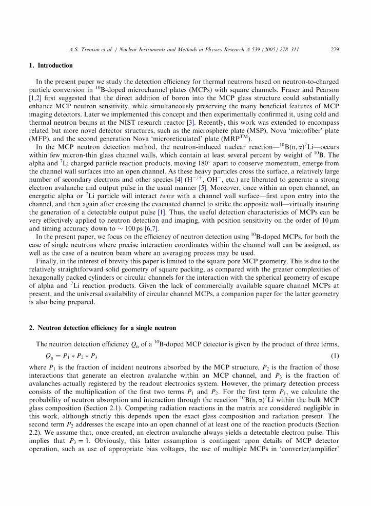
For all these reasons, it becomes attractive to simply stack several MCPs together, in the widely usedchevron or Z-stack arrangement [5]. Not only are pulse-counting gain levels of � 106 to 107 reached,allowing electronic imaging readout methods to be used, but total neutron absorption is also increased, asdetermined by the overall MCP thickness. At the same time, the two or more detectors can be stacked (seeFig. 3) in order to increase the absorption efficiency to virtually 100%, as used commonly with other
ARTICLE IN PRESS
Fig. 3. Schematic diagram of ‘‘stacked’’ thermal neutron detector. A neutron capture reaction takes place in 10B doped MCP converter
positioned above standard MCP stack (MCP-amplifier). The output charge cloud is collected by a readout element that is transparent
to neutrons (grid, cross delay line anode made of the necessary materials, etc.). The operating voltage of the detector does not increase
with the number of MCP stacks.
A.S. Tremsin et al. / Nuclear Instruments and Methods in Physics Research A 539 (2005) 278–311 283
neutron detection devices. The grids collecting signal electrons, shown in Fig. 3, can be replaced by aposition-sensitive anode made of materials nominally transparent to neutrons, thus providing positionsensitivity in the stacked detector.
Finally, gamma rays and minimum ionizing particles (e.g., cosmic ray muons) produce weak interactionsvia the photoelectric effect, Compton effect or pair production, and scales with MCP thickness with adetection efficiency of � 1–2% per mm [12] for most channel geometries. At first glance, this might seemattractive as the 10Bðn;aÞ7Li reaction yields a 0.48MeV gamma ray (94% branching ratio) when the excitedlithium nucleus quickly ð� 0:1 psÞ returns to its ground state. This event would only add to the detectionefficiency. However, this addition would be quite insignificant compared with the signal from the alphaparticle and 7Li reaction products. Thus simply increasing MCP thickness may not be a desirable approach,particularly in sensitive neutron detection applications where minimizing the simultaneous detectionsensitivity of gammas is critical. In some neutron detection applications, a relatively high flux gamma rayfield may accompany the neutron signal, creating a background interference. The competing requirementsof maximum bulk neutron absorption with minimum bulk gamma absorption can therefore work at crosspurposes. Neutron–gamma discrimination using techniques such as pulse analysis or fast timing, commonlyemployed with other solid-state neutron detection schemes [13], and the separation of neutron capture andelectron multiplication in front- and back-MCPs [14] are currently under investigation.
2.2. Escape probability P2 of 4He and 7Li nuclei reaction products
A reaction product, either an alpha or 7Li particle, has to escape into an open MCP channel to initiate anelectron avalanche. If both the alpha and the 7Li escape into a channel, only one of them needs be taken
ARTICLE IN PRESS
A.S. Tremsin et al. / Nuclear Instruments and Methods in Physics Research A 539 (2005) 278–311284
into account, since either particle corresponds to the same neutron capture event. Therefore, we firstcalculate the higher probability of alpha escape into an MCP channel and then consider those 7Li particlescases where the associated alpha is completely absorbed by the MCP glass (i.e., does not escape into anopen channel).
In the present model, we assume that if neutron absorption inside an MCP wall happens within theescape range from the pore, then the alpha (and/or 7Li) particle escapes into the MCP pore and produces anelectron avalanche with unit probability. This assumption corresponds to the lowest estimate of probabilityP2: Secondary effects leading to electron cascades, due to knock-on particles, induced X-ray emission,reaction gamma, etc. are ignored. The ranges of alpha and 7Li particles depend on their energies; for thecurrent neutron-sensitive MCP glass compositions developed by Nova, the escape ranges R1 areapproximately 3:54mm for 1472 keV and 4:23mm for 1777 keV alpha, while for 7Li the ranges R2 are 1.91and 2:15mm for 838 and 1014 keV 7Li. Values were calculated using SRIM 2000, The Stopping and Rangeof Ions in Matter, a set of computer programs developed through the works of Ziegler et al. [15]. Forsimplicity the modeled detection efficiency presented in this paper uses ‘‘averaged’’ escape ranges of R1 ¼
3:54 and R2 ¼ 2mm:Assigning position coordinates ðX ;Y Þ to the point of neutron interaction, we first calculate Pa
2—theprobability of escape into a channel for the alpha particle, then add the escape probability PLi
2 of a 7Liparticle corresponding to an alpha that is absorbed by the channel wall:
P2ðX ;Y Þ ¼ Pa2ðX ;Y Þ þ PLi
2 ðX ;Y Þ: (3)
The emission of the alpha and 7Li reaction products is isotropically distributed from the point of athermal neutron interaction. Another key feature of the MCP neutron capture process is the fact that alphaand 7Li particles are emitted diametrically. Therefore we can precisely calculate the probability PLi
2 ;corresponding to those 7Li particles associated with alpha particles absorbed by the channel wall glass. Adetailed description of our model for calculating parameters Pa
2ðX ;Y Þ and PLi2 ðX ;Y Þ is described in
Appendix C.
3. Averaged probability of neutron detection
The probability of single neutron detection, as described in Section 2, depends upon the position ðx0; y0Þ
of neutron impact upon the MCP surface, and angle ðy;jÞ of the trajectory relative to the MCP axis.However, there is also interest in the less demanding case of imaging the flux of relatively intenseð1052109 cm�2 s�1Þ beams of neutrons, such as in radiography or scattering applications with researchreactor sources. In this case, the relevant quantity of interest for assessing detection efficiency will be theaveraged probability of neutron detection, which will now be derived.
In Section 2.1 we estimated the probability P1 of neutron absorption with the MCP wall, but not theprecise location within the wall where the absorption event occurred. To properly calculate the escapeprobability P2 of the alpha and 7Li particle reaction products, we must first know the coordinates ðX ;Y Þ ofthe point of neutron absorption. Obviously, when the neutron is absorbed closer to the wall surface, there isa greater chance for the reaction products to escape into an open channel and to initiate an electronavalanche.
Given a distribution function r2ðX ;Y Þ of the neutron absorption within an MCP wall we can calculatethe averaged probability hP2i ¼ hP2ðX ;Y Þi that either of the two reaction particles will escape into an openchannel:
hP2i ¼ hP2ðX ;Y Þi ¼
RdYR
P2ðX ;Y Þr2ðX ;Y ÞdXRdYRr2ðX ;Y ÞdX
: (4)
ARTICLE IN PRESS
A.S. Tremsin et al. / Nuclear Instruments and Methods in Physics Research A 539 (2005) 278–311 285
For a neutron beam with a uniform intensity distribution on the scale of 10215mm (MCP pitch) (that is,to ignore effects of self shielding) the distribution function r2ðX ;Y Þ can be assumed to be a constant (thecoordinates ðX ;Y Þ of the neutron absorption can be assumed uniformly distributed within the MCP walls,typically a few mm thick). Subsequently the integral of Eq. (4) becomes:
hP2ðX ;Y Þi ¼
d2
W2hPI
2ðX ;Y Þi þ 12
W 2
4hPII
2 ðX ;Y Þi
dW=4þ W 2=8
¼ 42R d=20 dY
RW=20 P2ðX ;Y ÞdX þ
R ðdþW Þ=2d=2 dY
RW=20 P2ðX ;Y ÞdX
ð2d þ W ÞW: ð5Þ
The averaging of Eq. (5) is carried out over areas I and II, which are shaded in Fig. 4. By symmetry, anyposition X ;Y within the channel wall can be represented by a corresponding point within the shaded area,where there are two regions: Region I, inside the wall parallel to the Y -axis (where 0o ¼ Yod=2) anddenoted by ðPI
2ðX ;Y ÞÞ; and Region II, inside the intersection between this wall and the perpendicular wallðd=2o ¼ Yoðd þ W Þ=2Þ; aligned with the X -axis, and denoted by ðPII
2 ðX ;Y ÞÞ: The averaged probabilitieshPI
2ðX ;Y Þi and hPII2 ðX ;Y Þi in Eq. (5) are normalized by the corresponding area, to obtain the total
averaged escape probability hP2ðX ;Y Þi: Finally, the total averaged detection efficiency is given by
hPi ¼ hP1ðx0; y0ÞihP2ðX ;Y ÞiP3: (6)
For a highly collimated (parallel) neutron beam normally incident ðy ¼ p=2Þ to an MCP with zero degreechannel bias (i.e., channels normal to the MCP input face) the averaged probability hP1ðx0; y0Þi is foundfrom:
hP1ðx0; y0Þi ¼ðW þ 2dÞW
ðW þ dÞ2P1jLeff¼Leff ð
W2 ;
W2 ;
p2;0Þ
: (7)
For the case of non-normal neutron incidence (y between ymin and ymax), and given that essentially allneutron beams used in research have a width greater than 10215 mm (the MCP pore-to-pore period), we
Fig. 4. Averaging the escape probability P2 over the neutron capture positions ðX ;Y Þ within the MCP wall. The averaging described
by Eq. (5) is done separately for regions I ðPI2Þ and II ðPII
2 Þ:
ARTICLE IN PRESS
A.S. Tremsin et al. / Nuclear Instruments and Methods in Physics Research A 539 (2005) 278–311286
can continue to assume that the coordinates ðX ;Y Þ for neutron absorption are uniformly distributed (dueto the finite thickness of the MCP walls and large aspect ratio LMCP=d). Thus, Eqs. (5) and (6) can still beused to obtain the averaged detection efficiency, whereas Eq. (7) cannot be used. Instead, a morecomprehensive averaging can be substituted for the latter, using integration to obtain hP1i:
hP1i ¼ hP1ðx0; y0; y; pÞi
¼
R dþW
0dx0
R dþW
0dy0
R ymax
ymindyR jmax
jminP1ðx0; y0; y;jÞr1ðx0; y0; y;jÞdjR dþW
0dx0
R dþW
0dy0
R ymax
ymindyR jmax
jminr1ðx0; y0; y;jÞdj
�
R ymax
ymindyR jmax
jminr1ðy;jÞdj
R dþW
0dx0
R dþW
0P1ðx0; y0; y;jÞdy0R ymax
ymindyR jmax
jminr1ðy;jÞdj
ð8Þ
where r1ðx0; y0; y;jÞ is the distribution function for incident neutrons. The simplification evident in Eq. (8)is again based on the assumption that the neutron beam is larger than the channel pitch, and that thefunction r1ðx0; y0; y;jÞ is assumed constant within the limits of integration for coordinates ðx0; y0Þ 2
½0; d þ W �; so that r1ðx0; y0; y;jÞ � r1ðy;jÞ:
4. Model predictions
The neutron detection efficiency is a parameter of great interest in most neutron detection applications,particularly at low neutron fluence. Until recently, MCPs have been optimized for the sensitive detection ofmany other types of particles—electrons, ions, and especially photons in the spectral range extending fromsoft X-ray wavelengths down to the visible, where photocathodes are usually employed. The individualMCP channel input surfaces (in some cases coated with a photocathode) convert incident particles intosecondary electrons, which then develop electron cascades and detectable pulses. For neutrons, the MCPbulk material itself acts as an analogue ‘photocathode’ or converter, where an incident neutron is convertedby boron absorption into secondary ionizing particles that then enter the MCP channels, liberating furthersecondary particles (e.g., electrons, protons, OH� ions, etc.) that then create electron cascades and outputpulses.
As described earlier, the efficiency of this conversion process depends upon the product P1 � P2—theprobability P1 of neutron absorption in the MCP glass walls that are doped with 10B atoms and thesubsequent probability of escape into a channel, P2; of at least one of the alpha or
7Li charged particles. Weuse this model to derive expressions for P1 and P2 to allow prediction of absolute MCP neutron detectionefficiencies, optimized through careful choice of MCP parameters such as channel dimensions d, andchannel pitch or spacing (hence wall thickness W ), and the overall MCP thickness LMCP: Also important isthe level of boron-doping incorporated in the alkali lead silicate glass, which is constrained by complex andexacting fiber draw and MCP fabrication processes.
Obviously, there can be severe constraints on variations allowed in the structural variables of MCPs (e.g.,d; W ; and LMCP), including allowances for proper electrical operation, issues involving mechanicalstrength, and even issues of cost. For example, it is desirable to minimize the channel wall thickness in orderto maximize the escape probability P2 of the reaction products. However, the MCPs having the thinnestchannel walls, corresponding to the smallest channel diameters (2mm; available commercially from Burle[16]), represent a considerable technological achievement in its own right, given the fragility of submicronglass channel walls and the very high applied fields ð� 10 kV=mmÞ that must be sustained across the MCPglass, needed to accelerate secondary electrons above the first crossover potential ð� 20 eVÞ before strikingthe opposing channel wall [10]. Unfortunately, one of the essential MCP manufacturing steps of acid core
ARTICLE IN PRESS
A.S. Tremsin et al. / Nuclear Instruments and Methods in Physics Research A 539 (2005) 278–311 287
etch becomes essentially impossible for large LMCP=d ratios ð4500 : 1Þ; especially given the presence ofboron, which only increases acid solubility. Various tradeoffs and compromises in MCP design must bemade. Therefore, the simulation results presented in this section correspond to a reasonable set of MCPparameters realistically attainable with current manufacturing practices, and assume a level of 10B dopingof 10mol%:
4.1. Probability of neutron absorption P1
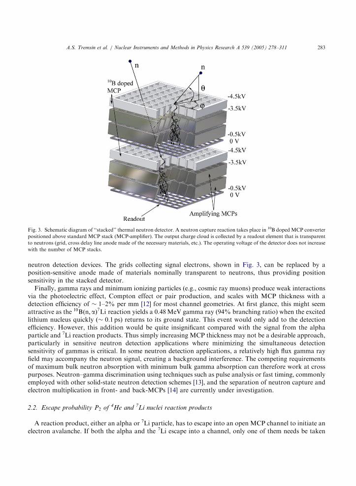
The probability of neutron absorption P1 for a single neutron is a function of neutron path inside theMCP glass walls Leff ; Eq. (2). Fig. 5 shows the portion of Leff relative to MCP thickness LMCP as a functionof incidence angle y for fixed angles j: The point of neutron incidence ðx0; y0Þ in these calculations waschosen to be in the center of the MCP wall. The path of neutron travel within the MCP glass quicklyreaches (within a few degrees) the value equal to ð1� AopenÞ; where Aopen ¼ W 2=ðd þ W Þ
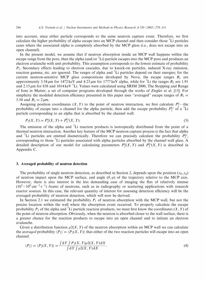
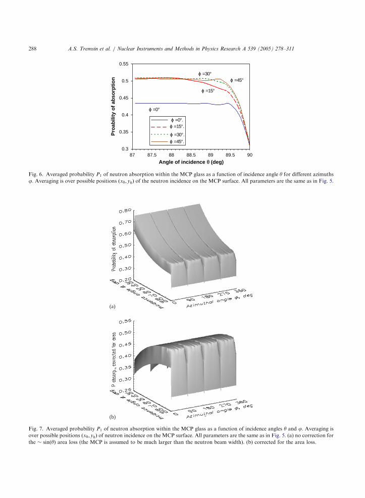
2 and is the openarea of the MCP (Aopen ¼ 64% for the case of the MCP modeled in Fig. 5). There are exceptions at anglesj ¼ 0�; 901, 1801 and 2701, when the neutron always travels within the MCP glass if the incidence pointðx0; y0Þ lies on the MCP wall. The probability of neutron absorption P1 averaged over incidence pointsðx0; y0Þ as a function of incidence angle y (for fixed angles j) is shown in Fig. 6. The averaging wasperformed assuming that the spatial distribution of the incident neutron beam was uniform within 10mm:The absorption probability is essentially independent of angle j; except for the special cases j ¼ 0�; 901,1801 and 2701. P1 reaches a plateau within a few degrees relative to the MCP normal. The efficiency ofneutron detection consequently exhibits a sharp drop, when the MCP pore axis coincides with the axis ofneutron incidence whenever the neutron beam is collimated to within d=LMCP radians.
Our experimental measurements of neutron absorption [17], performed with MCPs with circular poressupport the validity of the absorption part of our model. The results of the absorption probabilitycalculations for an MCP with 8mm pores on 11:5mm centers based on the model described in Section 2.1(modified for circular-pore geometry) agree with the experimental data obtained at the neutron guide beamline (NG-0) at the National Institute of Standards and Technology, a neutron beam with average energy of5meV. In the near future we hope to produce neutron collimators with good angular selectivity bysubstantially increasing the MCP aspect ratio ðLMCP=dÞ:
0
10
20
30
40
50
60
70
80
90
100
80 82 84 86 88 90
Angle of incidence θ (deg)
Lef
f (%
of
LM
CP)
ϕ =15°.ϕ =30°.ϕ =45°.
Fig. 5. Calculated length of single neutron path within the MCP glass walls as a function of incidence angle y for three different
azimuths j: d ¼ 8mm; W ¼ 2mm; LMCP ¼ 1000mm; neutron energy 0.025 eV ðsð10BÞ ¼ 3837bÞ; MCP glass has 10mol% of 10B, MCP
glass density 3:86 g cm�3: The neutron incidence position is in the middle of MCP wall ðx0; y0Þ ¼ ðW=2;W=2Þ; see Fig. 17.
ARTICLE IN PRESS
0.3
0.35
0.4
0.45
0.5
0.55
87 87.5 88 88.5 89 89.5 90
Angle of incidence θ (deg)
Pro
abili
ty o
f ab
sorp
tio
nϕ =0°.
ϕ =15°.
ϕ =30°.ϕ =45°.
ϕ =0°
ϕ =15°
ϕ =30° ϕ =45°
Fig. 6. Averaged probability P1 of neutron absorption within the MCP glass as a function of incidence angle y for different azimuths
j: Averaging is over possible positions ðx0; y0Þ of the neutron incidence on the MCP surface. All parameters are the same as in Fig. 5.
(b)
(a)
Fig. 7. Averaged probability P1 of neutron absorption within the MCP glass as a function of incidence angles y and j: Averaging is
over possible positions ðx0; y0Þ of neutron incidence on the MCP surface. All parameters are the same as in Fig. 5. (a) no correction for
the � sinðyÞ area loss (the MCP is assumed to be much larger than the neutron beam width). (b) corrected for the area loss.
A.S. Tremsin et al. / Nuclear Instruments and Methods in Physics Research A 539 (2005) 278–311288
ARTICLE IN PRESS
A.S. Tremsin et al. / Nuclear Instruments and Methods in Physics Research A 539 (2005) 278–311 289
Fig. 7 presents the calculated averaged probability of neutron absorption P1 as a function of both anglesy and j for square-pore MCP (the same MCP as in Figs. 5 and 6). In Fig. 7a there is no correction for theMCP area loss due to MCP tilt relative to the incident neutron beam (the width of the neutron beam ismuch smaller than the MCP width), while the same data corrected for � sinðyÞ area loss is shown in Fig. 7b(corresponding to the case when the width of the neutron beam is comparable or larger than the MCPwidth). In both cases variation in P1 is quite small for the incidence angles y in the range of 701to 881. Notethe 4-fold symmetry along the j-axis seen in these figures, which can be attributed to the invariance ofMCP geometry to 901rotations.
The stacking of three boron-doped MCPs obviously does not lead to a threefold increase of absorptionprobability P1; since the second MCP detects only those neutrons not detected by the first MCP. However,a stack of only three 1mm thick MCPs with 8mm pores (which can be manufactured using currenttechnology) increases the absorption probability from 0.52 to 0.9 (see Fig. 8). The results shown in Fig. 8correspond to a stack of three MCPs identical to the ones simulated in Figs. 5 and 6. Thus 90% of thermalneutrons should be absorbed within the MCP glass for a stack of three 125:1 LMCP=d; 8mm pore and 2mmwall MCPs with currently achievable level of 10mol% 10B doping.
4.2. Escape probability P2 of alpha and/or 7Li particles
The probability P2 that at least one of the particles produced in the neutron–boron reaction escapes intoan MCP pore is clearly a function of MCP wall thickness. The thinner the walls, the larger the probabilityP2: Depending on application, an appropriate combination of MCP structural parameters can be chosen,with the thickness of MCP walls d and the MCP pore width W among them. We start the simulation withthe function Pa
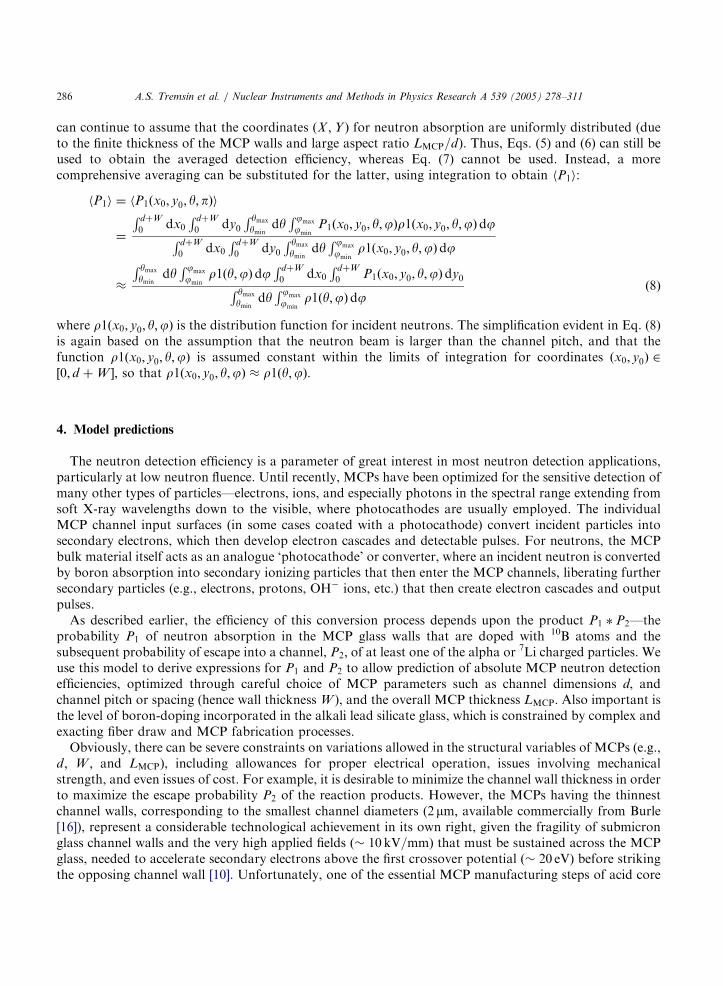
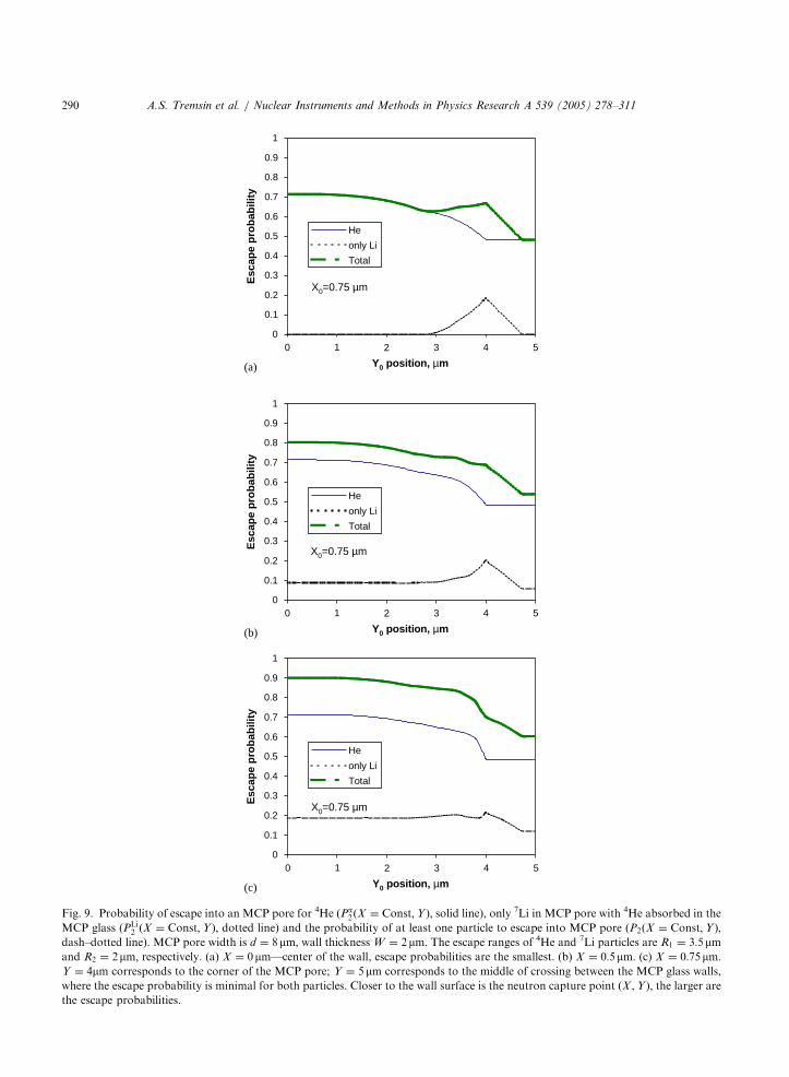
2ðX ;Y Þ from Eq. (C.23) for an MCP with 8mm pores and 2mm walls. Fig. 9 shows the escapeprobability for alpha particles (solid line) as a function of y0 position along the MCP wall with a fixed valueof x0 (depth within the wall, see Fig. 4). Pa
2ðX ;Y Þ decreases from 0.7 to 0.5 as the neutron capture pointmoves closer to the pore corner ðy0 ¼ 4mmÞ and then stays the same in region II of Fig. 4. This is becausethe radius of the escape sphere (R1; the range for alpha particles) is larger than the wall thickness W : Ourmodel accounts for both emission to the left pore and emission to the right pore. There is no significantchange of probability Pa
2ðX ;Y Þ with variation of position x0 within the wall (Figs. 9a–c), except for theregion close to the pore corner ð3mmox0o4mmÞ for the same reason that W is smaller than R1:
Fig. 8. Averaged probability P1 of neutron absorption within the MCP glass as a function of incidence angles y and j: No correction
for the area loss (the MCP is assumed to be much larger than the neutron beam width). Averaging is over possible positions ðx0; y0Þ ofneutron incidence on the MCP surface. All parameters are the same as in Fig. 5, except the MCP thickness LMCP is 3000mm:
ARTICLE IN PRESS
0
0.1
0.2
0.3
0.4
0.5
0.6
0.7
0.8
0.9
1
0 2 5
Esc
ape
pro
bab
ility
He
only Li
Total
0
0.1
0.2
0.3
0.4
0.5
0.6
0.7
0.8
0.9
1
Esc
ape
pro
bab
ility
He
only Li
Total
0
0.1
0.2
0.3
0.4
0.5
0.6
0.7
0.8
0.9
1
Y0 position, µm
Esc
ape
pro
bab
ility
He
only Li
Total
X0=0.75 µm
X0=0.75 µm
X0=0.75 µm
(a)
(b)
(c)
431
0 2 5
Y0 position, µm
431
0 2 5
Y0 position, µm
431
Fig. 9. Probability of escape into an MCP pore for 4He ðPa2ðX ¼ Const;Y Þ; solid line), only 7Li in MCP pore with 4He absorbed in the
MCP glass ðPLi2 ðX ¼ Const;Y Þ; dotted line) and the probability of at least one particle to escape into MCP pore ðP2ðX ¼ Const;Y Þ;
dash–dotted line). MCP pore width is d ¼ 8mm; wall thickness W ¼ 2mm: The escape ranges of 4He and 7Li particles are R1 ¼ 3:5mmand R2 ¼ 2mm; respectively. (a) X ¼ 0mm—center of the wall, escape probabilities are the smallest. (b) X ¼ 0:5mm: (c) X ¼ 0:75mm:Y ¼ 4mm corresponds to the corner of the MCP pore; Y ¼ 5mm corresponds to the middle of crossing between the MCP glass walls,
where the escape probability is minimal for both particles. Closer to the wall surface is the neutron capture point ðX ;Y Þ; the larger arethe escape probabilities.
A.S. Tremsin et al. / Nuclear Instruments and Methods in Physics Research A 539 (2005) 278–311290
ARTICLE IN PRESS
A.S. Tremsin et al. / Nuclear Instruments and Methods in Physics Research A 539 (2005) 278–311 291
The dashed line in Fig. 9 represents the probability PLi2 ðX ;Y Þ of 7Li particle escape into an MCP pore,
only for the case when an alpha is absorbed in the MCP wall glass. Those are the only particles that result inseparate events, contributing to the total probability of neutron detection P2: From Fig. 9, PLi
2 ðX ;Y Þ has astrong dependence on both x0 and y0 positions of the neutron capture reaction. The closer x0 is to the MCPwall, the larger the contribution of 7Li particles to the detection process, since more alpha particles (whichare emitted into the opposite pore) are absorbed in the MCP glass. Thus the total probability of neutrondetection P2ðX ;Y Þ increases as the neutron is absorbed closer to the MCP wall surface. More detailedinformation on the dependence of escape probability from both x0 and y0 for the same MCP geometry isshown in Figs. 10–12a. The dark area in the insert in Fig. 10 shows the region of the MCP wall for whichthe data are presented. The probability P2ðX ;Y Þ of at least one particle escaping into a pore reaches unity,when a neutron is absorbed far from the corner (away from the perpendicular wall) and close to the wallsurface. The minimum of P2ðX ;Y Þ is correspondingly in the middle of the MCP wall crossover. Fig. 12bshows simulation results for an MCP with a pore diameter and wall thickness that is twice as large as thatdepicted in Fig. 11a.
Once the functions Pa2ðX ;Y Þ and PLi
2 ðX ;Y Þ are known, it is possible to calculate the averaged escapeprobabilities Pa
2 and PLi2 from Eq. (5) and thus find the second term ðP2Þ of Eq. (1) required for the
calculation of the neutron detection efficiency of a 10B-doped MCP detector. For the reasons explained inSection 3, functions Pa
2ðX ;Y Þ and PLi2 ðX ;Y Þ should be averaged over regions I and II (Fig. 4), in order to
find hP2i: The averaged escape probabilities for alpha and 7Li particles are presented in Figs. 13 and 14 asfunctions of the MCP pore width d and the wall thickness W. When the MCP pore width is a few timeslarger than the wall thickness, the alpha particle escape probability is not a strong function of pore width;this probability decreases with the increase of the wall thickness W. On the other hand, the contributionfrom 7Li recoil particles has its maximum at a wall thickness W corresponding to 4mm; but thiscontribution does not exceed about 22% for the range of parameters d and W under consideration.
The averaged escape probability P2 as a function of both parameters, d and W (Fig. 15a), and as afunction of the pore width d only (with wall thickness fixed, Fig. 15b), thus indicates that rather highneutron detection efficiencies can clearly be achieved. The escape probability P2 for an MCP having 8mmpores with 2mm walls (as is typical for current commercial MCP devices), can even be as high as � 78%:Taking into account the fact that the absorption probability P1 can approach unity (for a stacked detectorconfiguration, Section 2.1.1) and the fact that the probability of generating an electron avalanche P3 can be
x
y
Fig. 10. Probability of 4He escape into MCP pore Pa2ðX ;Y Þ as a function of neutron absorption point ðX ;Y Þ for the MCP with pore
width d ¼ 8mm and the wall thickness W ¼ 2mm: The insert shows the area inside the MCP wall for which the probability was
calculated.
ARTICLE IN PRESS
Fig. 11. Probability of 7Li escape into MCP pore PLi2 ðX ;Y Þ with the recoil 4He being absorbed in the MCP glass. Parameters are the
same as in Fig. 10.
(a)
(b)
Fig. 12. Probability of at least one particle to escape into MCP pore—P2ðX ;Y Þ: (a) MCP pore width is d ¼ 8mm; wall thicknessW ¼ 2mm: (b) the MCP pore width is d ¼ 16mm; the wall thickness W ¼ 4mm: The probability P2ðX ;Y Þ reaches unity when the
neutron is absorbed close to the MCP wall surface and it drops to its minimum within crossing of the MCP walls.
A.S. Tremsin et al. / Nuclear Instruments and Methods in Physics Research A 539 (2005) 278–311292
ARTICLE IN PRESS
Fig. 14. The averaged probability of 7Li escape into MCP pore hPLi2 ðX ;Y Þi as a function of the MCP pore width d and wall thickness
W : Averaging is done over all possible coordinates of neutron absorption ðX ;Y Þ; Eq. (5), Fig. 4.
Fig. 13. The averaged probability of 4He escape into MCP pore hPa2ðX ;Y Þi as a function of the MCP pore width d and wall thickness
W : Averaging is done over all possible coordinates of neutron absorption ðX ;Y Þ according to Eq. (5) (see also Fig. 4).
A.S. Tremsin et al. / Nuclear Instruments and Methods in Physics Research A 539 (2005) 278–311 293
close to unity (see Section 2), it is evident that very efficient neutron counting using MCP-based detectorswith high spatial resolution ð� 10 mmÞ and sub-nanosecond timing capability becomes feasible.
Acknowledgements
The authors would like to thank George Lamaze, Heather Chen-Mayer, and David Mildner of the NISTNuclear Methods Group for assistance in the early experiments confirming the effectiveness of boron-doped MCPs and his help with the manuscript. We also thank Paul White of Nova Scientific, GeorgeFraser of the University of Leicester, Richard Lanza of MIT, and Oswald Siegmund of the Space SciencesLaboratory, University of California at Berkeley for their involvement at various levels.
ARTICLE IN PRESS
0
0.1
0.2
0.3
0.4
0.5
0.6
0.7
0.8
0.9
5 10 15 25
MCP pore width d, µm
Esc
ape
pro
bab
ility
W=2µm
W=3µm
W=4µm
W=6µm
7Li only
W=2µm
W=4µm
W=3µm W=6µm
20
(a)
(b)
Fig. 15. The averaged probability of at least one particle to escape into MCP pore—hP2ðX ;Y Þi (a) as a function of the MCP pore
width d and wall thickness W : (b) as a function of the MCP pore width d for a fixed MCP wall thickness W : Contribution of only 7Li
particles to the total probability is also shown. Averaging is done over all possible coordinates of neutron absorption ðX ;Y Þ; Eq. (5),Fig. 4.
A.S. Tremsin et al. / Nuclear Instruments and Methods in Physics Research A 539 (2005) 278–311294
Appendix A. Number density of10B atoms in MCP glass
The number of boron atoms per cm3 in MCP glass can be found using
N10B ¼ 2rglass �%mB2O3
MB2O3
(A.1)
where rglass is the MCP glass density, %mB2O3and MB2O3
are, respectively, the mass percentage of B2O3
molecules in the glass and the mass of one B2O3 molecule. %mB2O3can be found from the formula
%mB2O3¼ mB2O3
mB2O3=P
i mimi; where the denominator is the effective atomic weight, summed over allglass constituents and approximately equal to 90 for typical commercial MCP glasses. mB2O3
and mB2O3are,
respectively, the atomic mass of a B2O3 molecule and the mole fraction of B2O3 in the glass. The number ofboron atoms per unit volume in MCP glass can therefore be found from
N10B ¼ 2rglassmB2O3
mB2O3
MB2O3
Pi mimi
: (A.2)
ARTICLE IN PRESS
A.S. Tremsin et al. / Nuclear Instruments and Methods in Physics Research A 539 (2005) 278–311 295
Appendix B. Leff—effective length of neutron path within the MCP structure
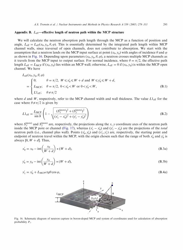
We will calculate the neutron absorption path length through the MCP as a function of position andangle, Leff ¼ Leff ðx0; y0; y;jÞ: This is essentially determined by the integrated path length within MCPchannel walls, since traversal of open channels, does not contribute to absorption. We start with theassumption that a neutron lands on the MCP input surface at point ðx0; y0Þ with angles of incidence y and jas shown in Fig. 16. Depending upon parameters ðx0; y0; y;jÞ; a neutron crosses multiple MCP channels asit travels from the MCP input to output surface. For normal incidence, where y ¼ p=2; the effective pathlength Leff ¼ LMCP if ðx0; y0Þ lies within an MCP wall; otherwise, Leff ¼ 0 if ðx0; y0Þ is within the MCP openchannel. We have
Leff ðx0; y0; y;jÞ
¼
0; y ¼ p=2; Wpx00pW þ d and Wpy0
0pW þ d;
LMCP; y ¼ p=2; 0ox00oW or 0oy0
0oW ;
L1eff ; yap=2
8>><>>: ðB:1Þ
where d and W ; respectively, refer to the MCP channel width and wall thickness. The value L1eff for thecase where yap=2 is given by
y are, respectively, the projections along the x; y coordinate axes of the neutron pathinside the MCP pore or channel (Fig. 17), whereas ðx0
1 � x00Þ and ðy0
1 � y00Þ are the projections of the total
neutron path (i.e., channel plus wall). Points ðx00; y
00Þ and ðx0
1; y01Þ are, respectively, the starting point and
endpoint of neutron travel within the MCP, with the origin chosen such that the range of both x00 and y0
0 isalways ½0;W þ d�: Thus,
x00 ¼ x0 � int
x0
W þ d
� �� ðW þ dÞ; (B.3a)
y00 ¼ y0 � int
y0
W þ d
� �� ðW þ dÞ; (B.3b)
x01 ¼ x0
0 þ LMCPctgy cosj; (B.4a)
e x
y
ϕ
θ
n
LMCP
z
(x0,y0)
Fig. 16. Schematic diagram of neutron capture in boron-doped MCP and system of coordinates used for calculation of absorption
probability P1:
ARTICLE IN PRESS
A.S. Tremsin et al. / Nuclear Instruments and Methods in Physics Research A 539 (2005) 278–311296
y01 ¼ y0
0 þ LMCPctgy sinj: (B.4b)
The function intðxÞ used in Eqs. (B.3a), (B.3b) is defined as the integer value of a positive real number x(without rounding to the closest integer). For negative x; it is the negative integer value with 1 subtracted(e.g. intð0:877Þ ¼ 0; intð21:32Þ ¼ 21; intð�2:14Þ ¼ �3; etc.).
Clearly SðporeÞy ¼ 0 for j ¼ 0 or j ¼ p; and SðporeÞ
x ¼ 0 for j ¼ p=2 or j ¼ 2p=3 (as the neutron travelsalong x- and y-axis, respectively). To find SðporeÞ
x and SðporeÞy for cases when they are not equal to zero, we
will initially determine the minimum and maximum indices of the channels which a neutron crosses duringits travel within an MCP,
imax ¼ intxe
W þ d
� �; imin ¼ int
xs
W þ d
� �; (B.5)
jmax ¼ intye
W þ d
� �; jmin ¼ int
ys
W þ d
� �(B.6)
where
xs ¼ minðx00; x
01Þ; xe ¼ maxðx0
0; x01Þ; (B.7a)
ys ¼ minðy00; y
01Þ; ye ¼ maxðy0
0; y01Þ: (B.7b)
Let us now sum all the projections of the neutron travel within individual channels,
SðporeÞx ¼
0; j ¼ p=2; 3p=2;Pimax
imin
xðporeÞi ; j ¼ 0; p;
Pimax
imin
Pjmax
jmin
xðporeÞij ; ja0;p=2; p; 3p=2;
8>>>>>><>>>>>>:
(B.8a)
x
y
(x0',y0')
(x1',y1')
ϕ
(xi ,yj)
y=kx+b
d
W
s s (xi ,yj)e e
Fig. 17. 2D projection of neutron path in a MCP with the wall thickness W and the pore width d :
ARTICLE IN PRESS
A.S. Tremsin et al. / Nuclear Instruments and Methods in Physics Research A 539 (2005) 278–311 297
SðporeÞy ¼
0; j ¼ 0; p;Pjmax
jmin
yðporeÞi ; j ¼ p=2; 3p=2;
Pimax
imin
Pjmax
jmin
yðporeÞij ; ja0;p=2;p; 3p=2
8>>>>>><>>>>>>:
(B.8b)
where xðporeÞi and y
ðporeÞj are projections of the neutron path within individual MCP channels for the simple
cases when, respectively, either SðporeÞy or SðporeÞ
x are equal to zero. These projections can be found from
xðporeÞi
¼
0; xeoxsi or xs4xe
i or yspW ;
minðxe; xei Þ xe4xs
i and xsoxei and ys4W ;
�maxðxs;xsi Þ;
8>><>>: ðB:9aÞ
yðporeÞj
¼
0; yeoysj or ys4ye
j or xspW ;
minðye; yej Þ ye4ys
j and ysoyej and xs4W
�maxðys; ysj Þ;
8>><>>: ðB:9bÞ
where xsi and xe
i are the left and right boundaries of the ith MCP channel,
xsi ¼ ðd þ W Þi; xe
i ¼ ðd þ W Þi þ d (B.10a)
and ysj and ye
j are the bottom and top boundaries of the jth MCP channel,
ysj ¼ ðd þ W Þj; ye
j ¼ ðd þ W Þj þ d: (B.10b)
For the remaining case, when ja0; p=2; p; and 2p=3; the projections of the neutron path within the ijth
MCP pore xðporeÞij and y
ðporeÞij are given by
xðporeÞij
¼
min½xe;minðxei ; ðy
ej � bÞ=kÞ�
�max½xs;maxðxsi ; ðy
sj � bÞ=kÞ�;
k40 and xei4ðys
j � bÞ=k and xsioðye
j � bÞ=k;
min½xe;minðxei ; ðy
sj � bÞ=kÞ�
�max½xs;maxðxsi ; ðy
ej � bÞ=kÞ�;
ko0 and xei 4ðye
j � bÞ=k and xsioðys
j � bÞ=k;
0; otherwise
8>>>>>>>>>>>><>>>>>>>>>>>>:
ARTICLE IN PRESS
A.S. Tremsin et al. / Nuclear Instruments and Methods in Physics Research A 539 (2005) 278–311298
yðporeÞij
¼
min½ye;minðyej ; ðx
ei � k þ bÞÞ�
�max½ys;maxðysj ; ðx
si � k þ bÞÞ�;
k40 and xei 4ðys
j � bÞ=k and xsioðye
j � bÞ=k;
min½ye;minðyej ; ðx
si � k þ bÞÞ�
�max½ys;maxðysj ; ðx
ei � k þ bÞÞ�;
ko0 and xei 4ðye
j � bÞ=k and xsioðys
j � bÞ=k;
0; otherwise
8>>>>>>>>>>>><>>>>>>>>>>>>:
where the line represented by y ¼ kx þ b corresponds to the neutron travel path in the XY-plane, withcoefficients k and b found from:
k ¼y01 � y0
0
x01 � x0
0
; b ¼ y00 � kx0
0: (B.11)
Having thus found N10B and Leff ; we can now calculate the probability of position- and angle-dependentsingle neutron absorption P1 � P1ðx0; y0; y;jÞ from Eq. (2). For sake of brevity, the results of calculationsfor the probability of a single neutron absorption are intentionally not shown. The probability averagedover all possible incidence positions ðx0; y0Þ is discussed in Sections 3 and 4. For most applications it is thisaveraged probability which characterizes the detector performance since in many applications utilizingneutron beams the beam dimensions are typically much larger than the channel-to-channel spacing (orpitch of MCPs), typically on the order of 10215mm:
Appendix C. Escape probability Pa2ðX ;Y Þ and PLi
2 ðX ;Y Þ of the alpha and 7Li particles
We introduce an imaginary sphere with radius set equal to the particle escape range, with the center atthe point of neutron reaction. A portion of the sphere surface (areas 1, 3 and 7 in Fig. 18 falls within theMCP channel wall, and corresponds to particles that fail to escape into an open channel, while otherportions of the surface fall within the open channel. This corresponds to alpha or 7Li particles that enterinto the open channel and initiate an electron avalanche. The probability of alpha or 7Li particle escape intoan open MCP channel is the ratio of the sphere surface contained inside an open channel to the totalsurface area 4pR2: In the most general case, the escape sphere consists of up to nine separate components(see Fig. 18), discussed in detail in Sections C.1 and C.2. Fig. 18 depicts only one hemisphere of alphaemission, located to the right, while the emission of recoil 7Li is represented by the hemisphere on the left,which has a smaller radius (i.e., 7Li particles corresponding to alphas emitted to the right can only beemitted to the left).
C.1. Escape probability Pa2ðX ;Y Þ of the alpha particle
First we consider the escape probability Pað0Þ2 for an alpha particle when it is far from the corner of a
channel, that is for Y in the range
0pYod=2� R1 (C.1)
ARTICLE IN PRESS
2
8
5 6 7 2 3 4 1
5 9
z x
y
MCP wall
Fig. 18. The escape hemispheres corresponding to 4He emission to the right MCP pore and 7Li recoil emission to the left pore. 4He
hemisphere: (1) area on the escape sphere, corresponding to absorption of 4He inside the MCP wall, parallel to y-axis. (2) Particles
escaping into an MCP pore and contributing to the detection process. (3) Particles absorbed in the wall, parallel to x-axis. (4) Particles,
which are emitted into an MCP pore and then strike the x-axis wall, contributing to the detection process. 7Li hemisphere: (5) 7Li
particles emitted into an MCP pore, corresponding to 4He particles also emitted into an MCP pore (not contributing to neutron
detection). (6) Particles, which are emitted into an MCP pore and then strike the x-axis wall, contributing to the detection process. (7)
Particles absorbed in the wall, parallel to x-axis (8) recoil 7Li particles corresponding to 4He absorbed in the x-axis wall. These 7Li
contribute to the detection process. (9) Particles escaping into an MCP pore and contributing to the detection process.
A.S. Tremsin et al. / Nuclear Instruments and Methods in Physics Research A 539 (2005) 278–311 299
where d is the channel width. We limit ourselves here only to positive values of Y ; since the equations fornegative Y are completely symmetric with respect to the coordinate system origin at the center of the MCPchannel wall. The distance to the nearest MCP channel is
L� ¼W
2� x (C.2)
where Lþ corresponds to emission to the right, with L� emission to the left.For Y as determined by Eq. (C.1), the escape probability is the ratio of that part of the escape sphere Sa;0;
lying within an MCP channel (the combined areas 2, 3 and 4 of Fig. 18 and including portions of the lefthemisphere not depicted in the figure) to the total spherical surface 4pR2: The portion of the sphere lyingwithin an open MCP channel is cut by the plane of a channel wall (either X ¼ W=2 or X ¼ �W=2). Theescape probability then becomes:
Pað0Þ2 ðX ;Y Þ � P
að0Þ2 ðX Þ ¼
1
4pR21
½Sþa;0ðX Þ þ S�
a;0ðX Þ� (C.3)
where
S�a;0ðX Þ ¼ F ðL�ðX Þ;R1Þ; (C.4)
ARTICLE IN PRESS
A.S. Tremsin et al. / Nuclear Instruments and Methods in Physics Research A 539 (2005) 278–311300
F ðL;RÞ ¼2pR2 1� L
R
� �; LoR;
0; LXR:
((C.5)
There is no particle escape into an open channel when L� is less than R, since particles must travel adistance 4R before they reach the channel surface.
When the escape sphere cuts into the perpendicular wall (where the walls parallel to the x-axis willsubsequently be referred to as ‘perpendicular’ walls),
d=2� R1pYod=2 (C.6)
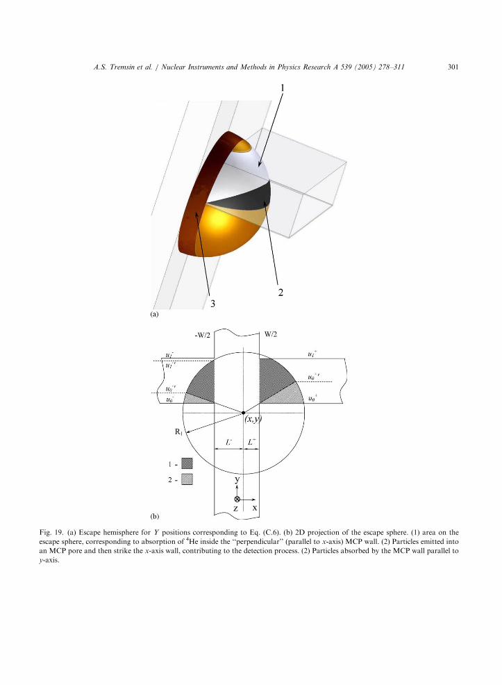
the situation becomes more complicated. Here, a portion of the escape sphere will correspond to alpha or7Li particles emitted into the perpendicular MCP wall. Therefore, we must subtract Area 1 of the escapesphere from the hemisphere shown in Fig. 19. These particles, emitted into Areas 1 and 3, will notcontribute at all to the neutron detection process. Emission into Area 2 corresponds to particles that exitthe MCP channel wall and then strike the surface of the perpendicular wall, inducing an electron avalanche.We therefore need not subtract from the escape probability P
að0Þ2 ; the total escape sphere area subtended
within the perpendicular channel wall Swall;1: Area 1 of the escape sphere can be found by first calculatingthe combined areas 1 and 2 (Swall;1 or the surface subtended by the perpendicular wall and the planeX ¼ �W=2 for left- and right-escaping particles), and then subtracting the Area 2 from the escape sphere,�Swall;2: The reason we first calculate the area of the combined portions is that Area 2 vanishes when the Y
coordinate lies in the range d=2pYpd=2þ W ; see Section C.1.2, below.
C.1.1. Area of the surface on the escape sphere Swall;1 subtended by a perpendicular MCP wall
The equation for the surface of a sphere with radius R is
ðx � x0Þ2þ ðy � y0Þ
2þ ðz � z0Þ
2¼ R2: (C.7)
Substituting variables t ¼ x � x0; u ¼ y � y0 and v ¼ z � z0; we move the center of the escape sphere intothe ðt; u; vÞ center of coordinates. The element of the surface of this sphere can thus be expressed as [18]
The area of the escape sphere subtended by the perpendicular channel wall (i.e., the combined Areas 1and 2 of Fig. 19) can be found by integrating Eq. (C.9) with a proper selection of integration limits (with u
varying between u0 and u1 as in Fig. 19b, and v varying between �ffiffiffiffiffiffiffiffiffiffiffiffiffiffiffiffiffiffiffiffiffiffiffiffiffiffiffiR2 � L2 � u2
pand
ffiffiffiffiffiffiffiffiffiffiffiffiffiffiffiffiffiffiffiffiffiffiffiffiffiffiffiR2 � L2 � u2
p):
Swall;1
¼
Z ZdS ¼
Z u1
u0
duTimes
Z ffiffiffiffiffiffiffiffiffiffiffiffiffiffiffiffiR2�L2�u2
Fig. 19. (a) Escape hemisphere for Y positions corresponding to Eq. (C.6). (b) 2D projection of the escape sphere. (1) area on the
escape sphere, corresponding to absorption of 4He inside the ‘‘perpendicular’’ (parallel to x-axis) MCP wall. (2) Particles emitted into
an MCP pore and then strike the x-axis wall, contributing to the detection process. (2) Particles absorbed by the MCP wall parallel to
y-axis.
A.S. Tremsin et al. / Nuclear Instruments and Methods in Physics Research A 539 (2005) 278–311 301
ARTICLE IN PRESS
A.S. Tremsin et al. / Nuclear Instruments and Methods in Physics Research A 539 (2005) 278–311302
where L is the distance from the sphere center to the channel wall defined by Eq. (C.2) (Fig. 19b), and
r ¼ffiffiffiffiffiffiffiffiffiffiffiffiffiffiffiffiffiR2 � L2
pis the radius of the circle at the intersection of the plane u ¼ Const and the escape sphere.
Integrating Eq. (C.10), we obtain
Swall;1 ¼ 2R½Hðu1Þ � Hðu0Þ� (C.11)
where
HðuÞ ¼ u arcsin
ffiffiffiffiffiffiffiffiffiffiffiffiffiffiffiffiffiffiffiffiffiffiffiffiffiffiffiR2 � L2 � u2
R2 � u2
s0@
1A� L arctan
uffiffiffiffiffiffiffiffiffiffiffiffiffiffiffiffiffiffiffiffiffiffiffiffiffiffiffiR2 � L2 � u2
p
� �
þR
2arctan
Ru þ R2 � L2
LffiffiffiffiffiffiffiffiffiffiffiffiffiffiffiffiffiffiffiffiffiffiffiffiffiffiffiR2 � L2 � u2
p
� �þ
R
2arctan
Ru � R2 þ L2
LffiffiffiffiffiffiffiffiffiffiffiffiffiffiffiffiffiffiffiffiffiffiffiffiffiffiffiR2 � L2 � u2
p
� �ðC:12Þ
for u2oR2 � L2; La0; and RaL; while for other parameters HðuÞ is expressed by
HðuÞ ¼
0; u24R2 � L2;p2ðR � LÞ
u
juj; u2 ¼ R2 � L2;
p2
u; L ¼ 0;
0; RpL:
8>>>>>><>>>>>>:
(C.13)
Note that HðuÞ ¼ 0 for RpL; because here the escape sphere does not intersect the perpendicular channelwall at all.
The probability that an alpha particle is emitted into the combined Areas 1 and 2 of the escape sphere,for the region where Y lies in the range determined by Eq. (C.6), is
Pwall;1ðX ;Y Þ ¼Swall;1ðX ;Y Þ
4pR2¼
Hðu1Þ � Hðu0Þ
2pR: (C.14)
We now must determine the limits of integration u0 and u1; which correspond to distances from the spherecenter to the sides of the perpendicular wall along the Y -axis. If only one side of the perpendicular wallcrosses the escape sphere (where ju0j4r or ju1j4r), then the limits of integration should be set to the radiusr ¼
C.1.2. Probability of alpha particle absorption in a perpendicular channel wall
As mentioned earlier, some alpha particles do escape into an open channel and also strikea perpendicular channel wall, thereby producing an electron avalanche. In the opposite case, wherethe alpha is unable to escape into a channel, because it is absorbed by a perpendicular channelwall (Area 1 on the escape surface of Fig. 19), we must subtract the surface area of Section 2 (Fig. 19)on the escape sphere Swall;2 (which exists only for Y in the range of Eq. (C.6). Then, Swall;2 can be
determined in the same manner as Swall;1; with the integration done within the range u 2 ½u00; u
01�
ARTICLE IN PRESS
A.S. Tremsin et al. / Nuclear Instruments and Methods in Physics Research A 539 (2005) 278–311 303
ðu þ R sin2ðbÞÞ � signðuÞffiffiffiffiffiffiffiffiffiffiffiffiffiffiffiffiffiffiffiffiffiffiffiffiffiffiffiffiffiffiffiffiffiffiffiffiffiffiffiffiffiffiffiffiffiffiffiffiffiffiR2 sin2ðbÞ � u2
Note that escape to both sides of the channel wall (at distance Lþ and L� from the point of neutroncapture) is taken into account in Eq. (C.23).
For Y values in the range
d=2pYpd=2þ W (C.24)
the escape probability Pa2 can still be calculated from Eq. (C.23), since Area 2 of the escape sphere (Fig. 20)
vanishes (i.e., from Eq. (C.17) Pwall;2 ¼ 0 as u0 becomes negative).
C.2. 7Li escape probability PLi2 ðX ;Y Þ when alpha is absorbed within the MCP channel wall
As discussed above, only those 7Li particles emitted diametrically to its paired alpha particle that isentirely absorbed within an MCP channel wall are considered in total detection efficiency calculations. Ifthe alpha is emitted nominally to the right as viewed from the point of neutron reaction, then the associated7Li particle is emitted nominally to the left (and vice versa—unless they both are emitted parallel to theplane X ¼ Const; and both particles are contained within the wall). As before in the case of the alphaescape probability, we start with the simplest case P
Lið0Þ2 (the total escape probability of 7Li into an MCP
channel), when a neutron is absorbed far from the corner of a channel with Y in the range as in Eq. (C.1),0pYod=2� R1
PLið0Þ2 ðX ;Y Þ � P
Lið0Þ2 ðX Þ
¼1
4pR22
½SþLi;0ðX Þ þ S�
Li;0ðX Þ� ðC:25Þ
where SLi;0 represents the combined areas 2 and 3 of Fig. 21:
S�Li;0ðX Þ ¼ F ðL�ðX Þ;R2Þ: (C.26)
We now subtract those 7Li particles corresponding to alphas emitted into an open channel. Fig. 21 showsschematically Area 2 ðSLi;1Þ on the escape sphere, which has to be subtracted from SLi;0 (the combinedAreas 2 and 3). The only 7Li particles contributing to the total detection efficiency will be those emitted intoangles corresponding to Area 3 on the escape sphere (assuming such an area exists, as it depends on theW ;R1;R2 and X parameters in Fig. 21b–d). The area of the surface 2, �SLi;1; which is to be subtractedfrom SLi;0; can be found from:
SþLi;1ðX Þ ¼
F1þðX Þ; X40;
SþLi;0; Xp0;
(
S�Li;1ðX Þ ¼
F1�ðX Þ; Xo0;
S�Li;0; XX0
(
ARTICLE IN PRESS
Fig. 20. (a) Escape hemisphere for Y -positions corresponding to Eq. (C.24). (b) 2D projection of the escape sphere. (1) area on the
escape sphere, corresponding to absorption of 4He inside the ‘‘perpendicular’’ (parallel to x-axis) MCP wall.
A.S. Tremsin et al. / Nuclear Instruments and Methods in Physics Research A 539 (2005) 278–311 305
ARTICLE IN PRESS
A.S. Tremsin et al. / Nuclear Instruments and Methods in Physics Research A 539 (2005) 278–311306
where
F1ðX Þ�
¼
0; R1pW
2;
0; absðX ÞXR1 �W
2;R14
W
2;
F ðL�;R2Þ; R1 þ R24W ;
absðX ÞpW
2
R1 � R2
R1 þ R2;
F ðL�;R2Þ; R1 þ R2pW ;R14W
2; absðX ÞpR1 �
W
2;
FR2
R1L�;R2
� �;
W
2
R1 � R2
R1 þ R2oabsðX ÞoR1 �
W
2:
8>>>>>>>>>>>>>>>>>>>><>>>>>>>>>>>>>>>>>>>>:
When a neutron is absorbed far from the channel corner, this absorption can result in both alpha and 7Liparticles escaping into a channel. However, both of those particles correspond to only a single neutronevent. The probability of 7Li particles not contributing to the neutron detection event, is
PLið1Þ2 ðX ;Y Þ � P
Lið1Þ2 ðX Þ
¼1
4pR22
½SþLi;1ðX Þ þ S�
Li;1ðX Þ� ðC:27Þ
and the probability of 7Li contributing to the unique detection event is then determined by
PLi2 ðX ;Y Þ ¼ P
Lið0Þ2 ðX Þ � P
Lið1Þ2 ðX Þ � P
Lið2Þ2 ðX ;Y Þ þ P
Lið3Þ2 ðX ;Y Þ: (C.28)
The two new terms introduced in Eq. (C.28) take into account the case of particle absorption in theperpendicular MCP wall: P
Lið2Þ2 is the probability of a Li particle being absorbed in the perpendicular MCP
wall, and PLið3Þ2 is the probability of Li escaping into the open channel, with the corresponding recoil alpha
particle being totally absorbed by the perpendicular channel wall.
C.2.1. Probability PLið2Þ2 of 7Li absorption in a perpendicular channel wall
If a neutron is absorbed close to the channel corner, certain 7Li particles will be entirely absorbed insidethe MCP perpendicular walls (similar to case of alpha absorption discussed in Section C.1.2). Here, thecalculation is complicated by the fact that we have to subtract only those Li particles absorbed in the wall,which were not taken into account in P
Lið1Þ2 : Therefore, we first calculate the probability of 7Li particle
emission into the perpendicular wall, but with a new escape range R2:
Some of the 7Li particles emitted into the perpendicular wall were already accounted for as ‘non-escaping’ particles in the previous section (SLi;1 in Eq. (C.27) as well as the corresponding surface Area 2 inFig. 21). We reduce P
Lið1Þwall by subtracting those particles already accounted for in Eq. (C.29), shown as Area
1 in Fig. 22.
PLið2Þwall ðX ;Y Þ ¼ ðFLi
wallðX ;Y ÞÞþþ ðFLi
wallðX ;Y ÞÞ�
where FLiwallðX ;Y Þ
�¼ ðPwall;1ðX ;Y Þ
�� Pwall;2ðX ;Y Þ
�ÞjL�ðX Þ¼L�0
;W�¼ðW 0Þ�;d�
¼ðd 0Þ�;R¼R2
ARTICLE IN PRESS
Fig. 21. (a) Escape hemispheres for 4He (right) and 7Li (left) for Y -positions corresponding to Eq. (C.6). (b)–(d) 2D projection of the
escape spheres. (b) All 7Li particles add to the escape probability P2 as none of them correspond to recoil 4He escaped into an MCP
pore. (c) Lþ0
4L�: some Li add up to the detection efficiency. (d) Lþ0
oL�: All 7Li particles correspond to 4He escaped into an MCP
pore already: none of 7Li add to the escape probability P2: (1)4He particles are emitted into an MCP pore. (2) 7Li particles that already
have recoil 4He in the opposite MCP pore—not adding to the probability P2: (3)7Li particles emitted into an MCP pore while their
corresponding 4He are absorbed within the wall glass should be counted as separate detection events adding to the probability P2:
A.S. Tremsin et al. / Nuclear Instruments and Methods in Physics Research A 539 (2005) 278–311 307
ARTICLE IN PRESS
A.S. Tremsin et al. / Nuclear Instruments and Methods in Physics Research A 539 (2005) 278–311308
Pwall;1ðX ;Y Þ is calculated by combining Eqs. (C.12)–(C.15), and Pwall;2ðX ;Y Þ is calculated from(C.17)–(C.22). For Pwall;1ðX ;Y Þ; we set u�
min u1;ffiffiffiffiffiffiffiffiffiffiffiffiffiffiffiffiffiffiffiffiffiffiffiffiR2
2 � ðL�0Þ2
q� �� u0
L�0
L�; u040; u140;
W2; u0 � u1p0;
8>>>>><>>>>>:
(C.31)
Finally, the probability that Li particles are emitted into the perpendicular channel wall but are not takeninto account in P
Lið1Þ2 is
PLið2Þ2 ðX ;Y Þ ¼ ðP
Lið1Þwall ðX ;Y Þ � P
Lið2Þwall ðX ;Y ÞÞ (C.32)
C.2.2. The probability PLið3Þ2 of 7Li escaping into the channel, with the corresponding alpha particle being
entirely absorbed in a perpendicular MCP wall
In previous sections we eliminated recoil 7Li particles that correspond to the alpha particles emitted intoan open channel, P
Lið1Þ2 (with none of the alpha particles emitted into the perpendicular wall). We then
continued calculating the probability that the 7Li particle itself is absorbed by the perpendicular MCP wall,PLið2Þ2 : We now have to correct P
Lið1Þ2 for those recoil 7Li particles that are emitted into a channel but with
the corresponding alpha particles absorbed entirely by the perpendicular channel wall (Area 3 in Fig. 23).As in previous sections, we take into account emission both to the left and right:
PLið3Þ2 ðX ;Y Þ ¼ ðGLi
He�wallðX ;Y ÞÞþ
þ ðGLiHe�wallðX ;Y ÞÞ
�:
We first calculate u0 and u1 from Eq. (C.15), for either Lþ or L� and R ¼ R1; u�0 � u0ðR1;L
�Þ; u�1 �
u1ðR1;L�Þ: (For the remainder of this section, u0 and u1 denote the values calculated from (C.15) using L�
and R1:) There are two possible combinations of the parameters X ; Y ; d and W leading to differentequations for calculation of GLi
a�wallðX ;Y Þ:The first is:(1) u�
0 ðR1;L�Þ � u�
1 ðR1;L�Þ40; as in Figs. 23a and b:
GLia�wallðX ;Y Þ
�¼ ðPwall;1ðX ;Y Þ � Pwall;2ðX ;Y ÞÞjd¼ðd 00
Þ�;W¼ðW 00Þ
�;L¼ðL00Þ� ;R¼R2
ARTICLE IN PRESS
Fig. 22. Correction for Li particles emitted into the perpendicular wall, which were already subtracted in Eqs. (C.27) and (C.28) as
surface area 2 of Fig. 21 (or combined surfaces 1 and 2 in this figure). (a), (b) 4He escaping to the right and 7Li to the left for Y
positions corresponding to Eq. (C.6). (c) Y positions corresponding to condition (C.24). (1) 7Li particles emitted into the perpendicular
wall, which were already subtracted as the ones already having recoil 4He in the MCP pore and to be added back as FLiwallðX ;Y Þ
�: (2)7Li particles, which already have recoil 4He in the opposite MCP pore—not adding to the probability P2:
A.S. Tremsin et al. / Nuclear Instruments and Methods in Physics Research A 539 (2005) 278–311 309
where both Pwall;1 and Pwall;2 are calculated from Eq. (C.12)–(C.14) and (C.17)–(C.22), respectively, with theparameters d; L; R and W changed to d 00; L00; R2 and W 00: L00 is found from Eq. (C.35), d 00; and W 00 usingthe following:
d�00¼ d � 2 minðju0ðR1;L
�Þj; ju1ðR1;L�ÞjÞ 1�
L�00
L�
!" #; (C.33)
ARTICLE IN PRESS
Fig. 23. Correction for recoil Li particles corresponding to He particles emitted into the perpendicular MCP wall. Particles in area 3
have been eliminated from the detection process in Eqs. (C.27) and (C.28) as surface area 2 of Fig. 21 and have to be added back as
PLið3Þ2 : (a), (b) 4He escaping to the right and 7Li to the left for Y positions corresponding to Eq. (C.6). (c) Y positions corresponding to
condition (C.24) (1) 4He particles absorbed in the perpendicular wall. (2) 4He particles, which are emitted into the MCP pore and then
strike the x-axis wall, contributing to the detection process. (3) 7Li particles in the MCP pore, with the corresponding recoil 4He
absorbed in the ‘‘perpendicular’’ MCP wall, to be added back as PLið3Þ2 :
A.S. Tremsin et al. / Nuclear Instruments and Methods in Physics Research A 539 (2005) 278–311310
W�00¼
L�00
L� ju0ðR1;L�Þ � u1ðR1;L
�Þj: (C.34)
The second combination is:(2) u�
0 ðR1;L�Þ � u�
1 ðR1;L�Þp0; as in Fig. 23c:
GLia�wallðX ;Y Þ
�
¼ Pwall;1ðX ;Y Þju0¼ðu000Þ� ;u1¼ðu00
1Þ�;L¼ðL00Þ
� ;R¼R2
ARTICLE IN PRESS
A.S. Tremsin et al. / Nuclear Instruments and Methods in Physics Research A 539 (2005) 278–311 311
where Pwall;1 is calculated from Eqs. (C.12)–(C.14) with u0 and u1 changed to u000 and u00