Efficient multiview depth video coding using depth synthesis prediction Cheon Lee Byeongho Choi Yo-Sung Ho Downloaded from SPIE Digital Library on 25 Jul 2011 to 66.165.46.178. Terms of Use: http://spiedl.org/terms
Transcript
Efficient multiview depth video codingusing depth synthesis prediction
Cheon LeeByeongho ChoiYo-Sung Ho
Downloaded from SPIE Digital Library on 25 Jul 2011 to 66.165.46.178. Terms of Use: http://spiedl.org/terms
Optical Engineering 50(7), 077004 (July 2011)
Efficient multiview depth video coding using depthsynthesis prediction
Cheon LeeGwangju Institute of Science
and Technology261 Cheomdan-gwagiroBuk-guGwangju, 500-712, Republic of KoreaE-mail: [email protected]
Byeongho ChoiKorea Electronics Technology InstituteYatap-dong, Bundang-gu SeongnamGyeonggi Province, 463-816 Republic of Korea
Yo-Sung HoGwangju Institute of Science
and Technology261 Cheomdan-gwagiroBuk-guGwangju, 500-712, Republic of Korea
Subject terms: depth video coding; three-dimensional video coding; depth viewsynthesis; depth map coding.
Paper 100762R received Sep. 24, 2010; revised manuscript received Mar. 14,2011; accepted for publication May 25, 2011; published online Jul. 6, 2011.
1 IntroductionThe three-dimensional(3D) video provides depth impressionof the observed scenery with slight different viewpoints be-tween the left and right eyes, which stimulates the humanbrain to perceive distance of objects. Due to mature 3D tech-nologies from capturing to display, awareness and interestsare rapidly increasing among users.1–3 A key issue in 3Dvideo technology is how to produce a comfortable 3D sceneminimizing visual fatigues. Since most of the visual fatiguesare induced by the improper camera baseline, it can be solvedby selecting two proper viewpoint images among variousviewpoint images. In such application, a sufficient numberof viewpoint images should be sent to the 3D displays. How-ever, the huge amount of data due to the multiple views isa serious problem for service; hence, we need to develop anefficient video coding.
In response to such needs and interests, many researchersdeveloped various data formats and coding methods for ren-dering a 3D scene.4 Particularly, moving picture expertsgroup (MPEG) and joint video team have developed themultiview video coding (MVC), which compresses multi-view videos using high correlations between views.5 It isthe latest coding standard designed for coding the multiviewvideos efficiently. It employs an interview/temporal predic-tion structure based on the hierarchical B-picture coding toutilize high correlations among views. For the standardiza-tion of MVC, many coding techniques had been proposedsuch as the prediction structure,6 view synthesis prediction
methods,7–10 the illumination compensation method,11 andthe motion skip mode.12
By finalizing the standardization on MVC in 2008, ex-perts of MPEG discussed the advanced 3D video codingmethod which supports advanced stereoscopic viewing andautostereoscopic displays. Among various data formats sup-porting the free-view TV or the 3DTV, the multiview videoplus depth (MVD) format is selected for the 3D video system.According to the Plenoptic sampling theory, we can transmitonly few viewpoints including depth data composed with asparse camera arrangement instead of sending a large numberof views covering wide field-of-view to the decoder.13 By re-constructing the depth data at both the encoder and decoder,we generate arbitrary viewpoint images using a view syn-thesis algorithm, e.g., the depth image-based rendering.14–16
Because of the use of depth data, there are growing interestsin coding techniques that take advantage of the correlationamong depth views. The 3D video coding is under develop-ment by MPEG with a framework which involves the MVDformat.17
Since 2008, the standardization for the 3D video codinghas started by the MPEG 3DV ad hoc group as a secondphase of free-viewpoint TV (FTV) works.18 Experts haveset an extended framework which provides the high-qualityreconstruction of an arbitrary number of views for advancedstereoscopic processing functionalities and to support au-tostereoscopic displays.17, 18 Currently, the 3D video systemunder consideration involves the MVD format to renderarbitrary viewpoint images. For instance, instead of trans-mitting nine viewpoint videos to render them with nineview3D displays, we can transmit only three viewpoints and
Optical Engineering July 2011/Vol. 50(7)077004-1
Downloaded from SPIE Digital Library on 25 Jul 2011 to 66.165.46.178. Terms of Use: http://spiedl.org/terms
Lee, Choi, and Ho: Efficient multiview depth video coding using depth synthesis prediction
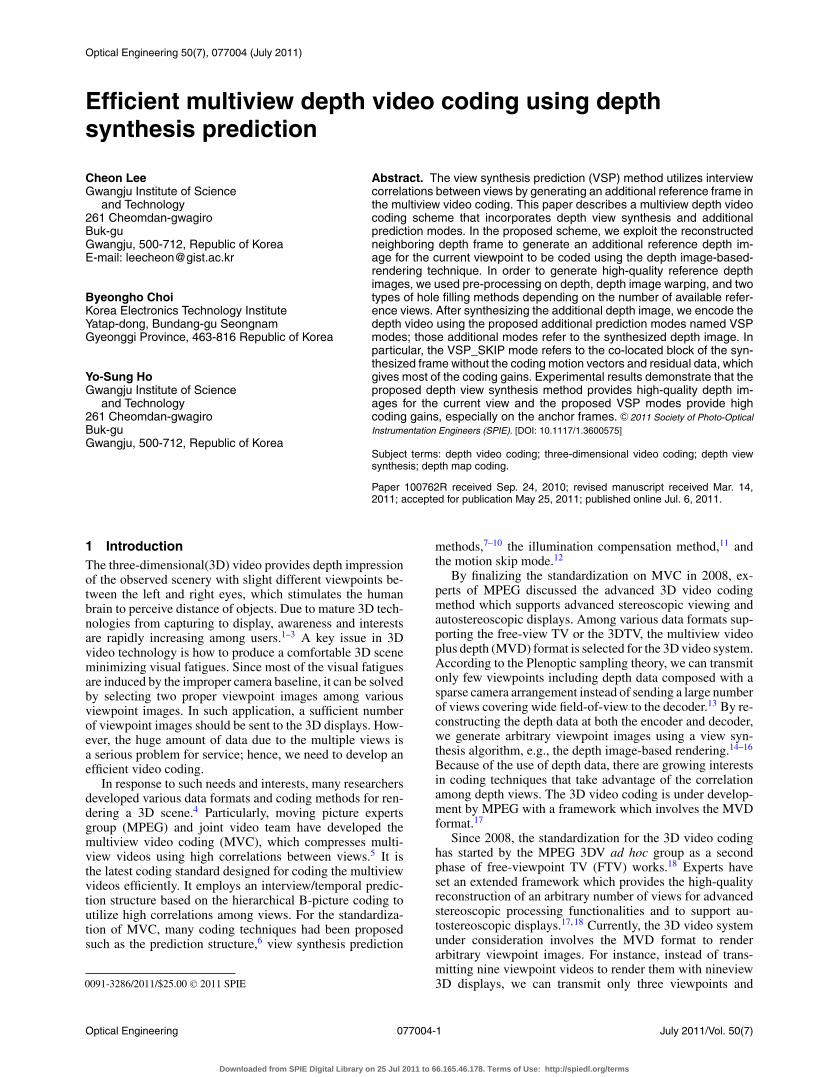
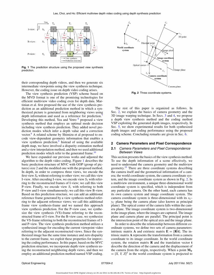
Fig. 1 The prediction structure using the proposed view synthesisprediction.
their corresponding depth videos, and then we generate sixintermediate viewpoints using the view synthesis technique.However, the coding issue on depth video coding arises.
The view synthesis prediction (VSP) scheme based onthe MVD format is one of the promising technologies forefficient multiview video coding even for depth data. Mar-tinian et al. first proposed the use of the view synthesis pre-diction as an additional prediction method in which a syn-thesized picture is generated from neighboring views usingdepth information and used as a reference for prediction.7
Developing this method, Yea and Vetro 8 proposed a viewsynthesis method that employs an optimal mode decisionincluding view synthesis prediction. They added novel pre-diction modes which infer a depth value and a correctionvector.8 A related scheme by Shimizu et al proposed to en-code view-dependent geometry information that enables aview synthesis prediction.9 Instead of using the availabledepth map, we have involved a disparity estimation methodand a view interpolation method, and then we used additionalprediction modes which refer to the generated frame.10
We have expanded our previous works and adjusted thealgorithm to the depth video coding. Figure 1 describes thebasic prediction structure of MVC with GOP (group of pic-tures) size 2 and the modified one with the proposed method.In depth, in order to compress three views, we encode thefirst view S0 without referring to other view; we call this viewI-view. After encoding I-view, we encode view S2 with refer-ring to the reconstructed frames of I-view; we call this viewP-view. Finally, we encode view S1 with referring to bothP-view and I-view simultaneously; we call this view B-view.Based on this prediction structure, we can add an additionalreference frame generated by a view synthesis method refer-ring to the adjacent reference views; we call this additionalframe view synthesis-frame and we named this approachview synthesis prediction. For the P-view case, we synthe-size the view synthesis (VS)-frame referring to the recon-structed frame of I-view. For the B-view case, we synthesizethe VS-frame referring to both the reconstructed frames of I-and P-view. The view synthesis prediction method utilizes asynthesized image for encoding the current viewpoint videoreferring to the adjacent reconstructed views. Since the syn-thesized image has the same time instance and zero disparityto the current frame, we exploit these properties for improv-ing the coding performance. In this paper, based on the MVCprediction structure, we incorporate depth view synthesis us-ing the reconstructed neighboring depth views, and then weemploy an additional prediction method named VSP coding.
Fig. 2 Three coordinate systems.
The rest of this paper is organized as follows. InSec. 2, we explain the basics of camera geometry and the3D image warping technique. In Secs. 3 and 4, we proposea depth view synthesis method and the coding methodVSP exploiting the generated depth images, respectively. InSec. 5, we show experimental results for both synthesizeddepth images and coding performance using the proposedcoding scheme. Concluding remarks are given in Sec. 6.
2 Camera Parameters and Pixel Correspondence
2.1 Camera Parameters and Pixel CorrespondenceBetween Views
This section presents the basics of the view synthesis method.To use the depth information of a scene effectively, weneed to understand the camera geometry and the multiviewgeometry.19 There are three coordinate systems describingthe camera itself and the geometrical information of a cam-era; the world coordinate system, the camera coordinate sys-tem, and the image coordinate system as shown in Fig. 2. Ina multiview environment, a unique three-dimensional worldcoordinate system is specified, which is independent fromany particular camera. On the other hand, each camera hasits own camera system and image coordinate system. Thecamera coordinate system is three-dimensional with its xC-yC plane being the camera plane (also known as principalplane). The optical center of the camera falls within the cam-era plane. The image coordinate system is two-dimensionalin the image plane, where the images are captured. The imageplane and camera plane are parallel. The principal point isthe intersection point of the optical axis and the image plane.
In order to describe the relationship between different co-ordinate systems, we define two sets of camera parameters:intrinsic matrix A and extrinsic matrix E = [R|t]. The in-trinsic matrix A represents the transformation from a cameracoordinate to its image coordinate. In the world coordinatesystem, the rotation matrix R and the translation vector tdescribe the direction of the camera and the displacement ofthe camera from the origin, respectively. When a point Mw= [X, Y, Z]T in the world coordinate system is projected to
Optical Engineering July 2011/Vol. 50(7)077004-2
Downloaded from SPIE Digital Library on 25 Jul 2011 to 66.165.46.178. Terms of Use: http://spiedl.org/terms
Lee, Choi, and Ho: Efficient multiview depth video coding using depth synthesis prediction
Fig. 3 Finding corresponding pixels between two views.
a pixel m = [u v]T into the image plane, we can map twopoints with the following relation as:
m̃ = A · R · Mw + A · t, (1)
where m̃ = [ u · Z v · Z Z ]T represents the projected pixelposition in the image coordinate system in homogeneousform.
Let the virtual viewpoint be the target viewpoint to besynthesized; there is neither available color nor depth im-ages. Then we need to find which pixel in the virtual viewcorresponds to the pixel in the reference view which has bothcolor and depth images. If a point Mw in the world coordinatesystem is projected to two separate cameras, as illustrated inFig. 3, we obtain two pixel positions mref = [uref vref]T andmvir = [uvir vvir]T as described in Eq. (2).{
m̃ref = Aref · Rref · Mw + Aref · tref
m̃vir = Avir · Rvir · Mw + Avir · tvir, (2)
where subscriptions ref and vir indicate the reference view-point and the virtual viewpoint, respectively. Since the avail-able data are camera parameters of each camera and the depthdata of the reference view, we can find 3D points correspond-ing to pixels of the reference image.
Finding the 3D position from the reference view is calledbackward projection. From Eq. (1), the projected pixel m̃is multiplied by the depth value Z, hence we can rewritethis as m̃ = [m|1]T · Z . Using this form deductively, we canfind the 3D position Mw by calculating inverse function ofEq. (2) as:
Mw = R−1ref · A−1
ref · [mref|1]T · Zref(mref) − R−1ref · tref (3)
where the scalar value Zref(mref) is the real depth value cal-culated as:
Zref(mref) = 1Dref (mref )
255 ·(
1Znear
− 1Zfar
)+ 1
Zfar
, (4)
where Dref(mref) is the pixel value of depth image of referenceview. Znear and Zfar are the depth range of a physical scene,20
and those values are given by the sequence provider.After determining the 3D point Mw, we can re-project it
into the virtual view to find mvir as described in Eq. (1) as:
m̃vir = Avir · Rvir · Mw + Avir · tvir, (5)
Fig. 4 Steps of depth synthesis.
where m̃vir is a homogeneous representation of a pixel; it isscaled by the depth value of Zref calculated by Eq. (4), hencethe pixel position mvir = [uvir vvir]T is derived by Eq. (6).
m̃vir = Zref(mref) · [mvir|1]T = Zref(mref) ·
⎛⎜⎝
uvir
vvir
1
⎞⎟⎠ . (6)
Substituting Mw in Eq. (3) for Eq. (5), we get the relationshipbetween two corresponding pixels as:
m̃vir = Avir · Rvir · R−1ref · A−1
ref · [mref|1]T · Zref(mref)
− Avir · Rvir · R−1ref · tref + Avir · tvir. (7)
In order to simplify this complex equation, we use a rep-resentative equation with g( ) hereinafter as:
m̃vir = g[mref, Zref(mref)] − tref,vir, (8)
where the function g( ) represents the first term of Eq. (7),and the vector tref,vir replaces the last two terms of Eq. (7) as:
Using this method, we determine the corresponding pixelsbetween the reference view and the virtual view.
3 Proposed Depth Synthesis Method for 3DVideo Coding
In this section, we describe the proposed depth synthesismethod for multiview depth video coding. Basically, we usethree steps for generating a virtual depth map as described inFig. 4: depth pre-processing, 3D depth image warping, andhole filling. In the pre-processing step, we reduce erroneousdepth values for the reconstructed image using a median filterto minimize image distortions. Next, we find correspondingpixels between the reference view and the virtual view asdescribed in Sec. 2. Finally, we fill the holes referring to thevalid pixels either from the synthesized image itself or fromthe other reference image. The first two steps are the samefor both P- and B-view cases, but we use different hole fillingmethods with respect to the view type.
3.1 Pre-Processing on Depth MapThe available depth data at the decoder is the reconstructedone according to the MVC prediction structure. Because the
Optical Engineering July 2011/Vol. 50(7)077004-3
Downloaded from SPIE Digital Library on 25 Jul 2011 to 66.165.46.178. Terms of Use: http://spiedl.org/terms
Lee, Choi, and Ho: Efficient multiview depth video coding using depth synthesis prediction
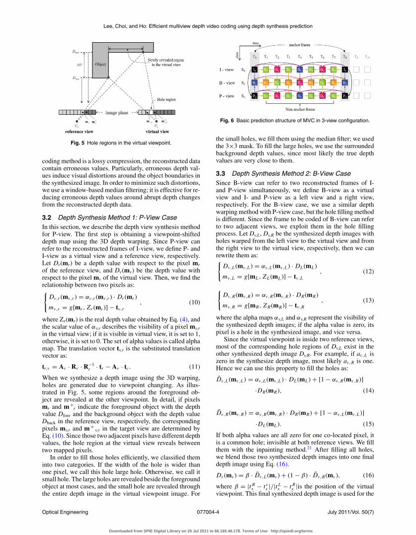
Fig. 5 Hole regions in the virtual viewpoint.
coding method is a lossy compression, the reconstructed datacontain erroneous values. Particularly, erroneous depth val-ues induce visual distortions around the object boundaries inthe synthesized image. In order to minimize such distortions,we use a window-based median filtering; it is effective for re-ducing erroneous depth values around abrupt depth changesfrom the reconstructed depth data.
3.2 Depth Synthesis Method 1: P-View CaseIn this section, we describe the depth view synthesis methodfor P-view. The first step is obtaining a viewpoint-shifteddepth map using the 3D depth warping. Since P-view canrefer to the reconstructed frames of I-view, we define P- andI-view as a virtual view and a reference view, respectively.Let Dr(mr) be a depth value with respect to the pixel mrof the reference view, and Dv(mv) be the depth value withrespect to the pixel mv of the virtual view. Then, we find therelationship between two pixels as:{
Dv,r (mv,r ) = αv,r (mv,r ) · Dr (mr )
mv,r = g[mr , Zr (mr )] − tv,r, (10)
where Zr(mr) is the real depth value obtained by Eq. (4), andthe scalar value of αv,r describes the visibility of a pixel mv,rin the virtual view; if it is visible in virtual view, it is set to 1,otherwise, it is set to 0. The set of alpha values is called alphamap. The translation vector tv,r is the substituted translationvector as:
tr,v = Av · Rv · R−1r · tr − Av · tc. (11)
When we synthesize a depth image using the 3D warping,holes are generated due to viewpoint changing. As illus-trated in Fig. 5, some regions around the foreground ob-ject are revealed at the other viewpoint. In detail, if pixelsmr and m+
r indicate the foreground object with the depthvalue Dfore and the background object with the depth valueDback in the reference view, respectively, the correspondingpixels mv,r and m+
v,r in the target view are determined byEq. (10). Since those two adjacent pixels have different depthvalues, the hole region at the virtual view reveals betweentwo mapped pixels.
In order to fill those holes efficiently, we classified theminto two categories. If the width of the hole is wider thanone pixel, we call this hole large hole. Otherwise, we call itsmall hole. The large holes are revealed beside the foregroundobject at most cases, and the small hole are revealed throughthe entire depth image in the virtual viewpoint image. For
Fig. 6 Basic prediction structure of MVC in 3-view configuration.
the small holes, we fill them using the median filter; we usedthe 3×3 mask. To fill the large holes, we use the surroundedbackground depth values, since most likely the true depthvalues are very close to them.
3.3 Depth Synthesis Method 2: B-View CaseSince B-view can refer to two reconstructed frames of I-and P-view simultaneously, we define B-view as a virtualview and I- and P-view as a left view and a right view,respectively. For the B-view case, we use a similar depthwarping method with P-view case, but the hole filling methodis different. Since the frame to be coded of B-view can referto two adjacent views, we exploit them in the hole fillingprocess. Let Dv,L, Dv,R be the synthesized depth images withholes warped from the left view to the virtual view and fromthe right view to the virtual view, respectively, then we canrewrite them as:{
Dv,L (mv,L ) = αv,L (mv,L ) · DL (mL )
mv,L = g[mL , ZL (mL )] − tv,L, (12)
{Dv,R(mv,R) = αv,R(mv,R) · DR(mR)
mv,R = g[mR, Z R(mR)] − tv,R, (13)
where the alpha maps αv,L and αv,R represent the visibility ofthe synthesized depth images; if the alpha value is zero, itspixel is a hole in the synthesized image, and vice versa.
Since the virtual viewpoint is inside two reference views,most of the corresponding hole regions of Dv,L exist in theother synthesized depth image Dv,R. For example, if av,L iszero in the synthesize depth image, most likely av,R is one.Hence we can use this property to fill the holes as:
If both alpha values are all zero for one co-located pixel, itis a common hole; invisible at both reference views. We fillthem with the inpainting method.21 After filling all holes,we blend those two synthesized depth images into one finaldepth image using Eq. (16).
As we mentioned in Sec. 1, we use the typical MVC predic-tion structure to encode the multiview depth video; namelythe I-B-P prediction structure as shown in Fig. 6, which is adetailed version of the prediction structure of Fig. 1. Afterencoding I-view, encoding P-view is followed referring tothe I-view’s reconstructed frames. For example, if the frameat S2T0 is the current frame to be coded, it refers to the S0T0frame. If the frame at S2T4 is the current frame, it refers toS0T4 frame as well as both S2T0 and S2T8 frames. In the samemanner, if the current frame is at S1T4 frame, it refers to twoS1T0 and S1T8 frames from the same viewpoint and two S0T4and S2T4 frames from the other views; in total, it uses fourreference frames.
Based on this prediction structure, we propose a codingmethod named VSP coding which exploits the interview ref-erence frames effectively. Since the input data represents thedepth information for every pixel, we can synthesize anyviewpoint depth image using the 3D warping technique. Toexploit this, we synthesize a depth map for the current viewusing the reference frames, and then we involve it as an ad-ditionally reference frame at the coder. Since the synthesizeddepth images have the same time instance with no disparity,it may improve coding performance. However, both increas-ing coding complexity and additionally the header data for
indicating the added frame are inevitable. In this work, wedo not focus on the complexity of the coder, but we care foronly the coding performance. In the future, we expect that therelated hardware technology will overcome this complexity.
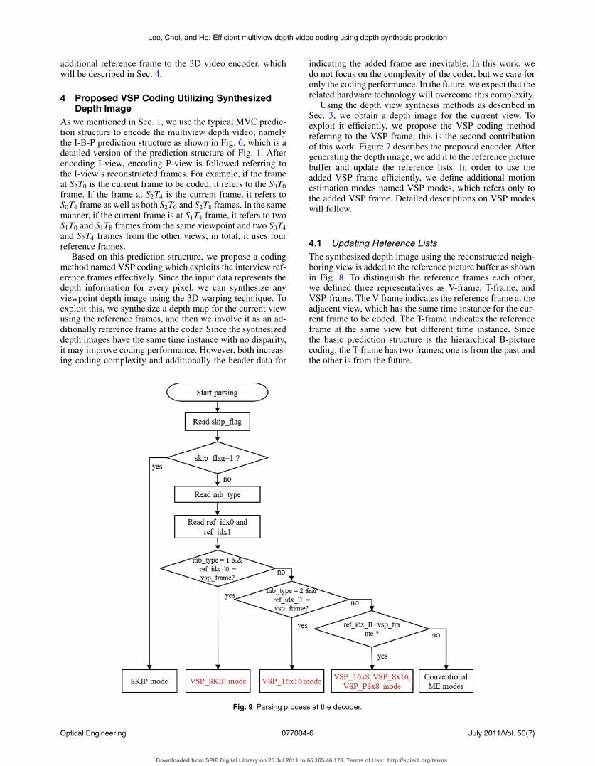
Using the depth view synthesis methods as described inSec. 3, we obtain a depth image for the current view. Toexploit it efficiently, we propose the VSP coding methodreferring to the VSP frame; this is the second contributionof this work. Figure 7 describes the proposed encoder. Aftergenerating the depth image, we add it to the reference picturebuffer and update the reference lists. In order to use theadded VSP frame efficiently, we define additional motionestimation modes named VSP modes, which refers only tothe added VSP frame. Detailed descriptions on VSP modeswill follow.
4.1 Updating Reference ListsThe synthesized depth image using the reconstructed neigh-boring view is added to the reference picture buffer as shownin Fig. 8. To distinguish the reference frames each other,we defined three representatives as V-frame, T-frame, andVSP-frame. The V-frame indicates the reference frame at theadjacent view, which has the same time instance for the cur-rent frame to be coded. The T-frame indicates the referenceframe at the same view but different time instance. Sincethe basic prediction structure is the hierarchical B-picturecoding, the T-frame has two frames; one is from the past andthe other is from the future.
Fig. 9 Parsing process at the decoder.
Optical Engineering July 2011/Vol. 50(7)077004-6
Downloaded from SPIE Digital Library on 25 Jul 2011 to 66.165.46.178. Terms of Use: http://spiedl.org/terms
Lee, Choi, and Ho: Efficient multiview depth video coding using depth synthesis prediction
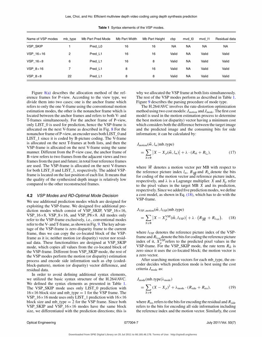
Table 1 Syntax elements of the VSP modes.
Name of VSP modes mb_type Mb Part Pred Mode Mb Part Width Mb Part Height cbp mvd_l0 mvd_l1 Residual data
VSP_SKIP 1 Pred_L0 16 16 NA NA NA NA
VSP_16×16 2 Pred_L1 16 16 Valid NA Valid Valid
VSP_16×8 6 Pred_L1 16 8 Valid NA Valid Valid
VSP_8×16 7 Pred_L1 8 16 Valid NA Valid Valid
VSP_8×8 22 Pred_L1 8 8 Valid NA Valid Valid
Figure 8(a) describes the allocation method of the ref-erence frames for P-view. According to the view type, wedivide them into two cases; one is the anchor frame whichrefers to only the one V-frame using the conventional motionestimation modes, the other is the nonanchor frame which islocated between the anchor frames and refers to both V- andT-frames simultaneously. For the anchor frame of P-view,only LIST_0 is used for prediction, hence the VSP-frame isallocated on the next V-frame as described in Fig. 8 For thenonanchor frame of P-view, an encoder uses both LIST_0 andLIST_1 since it is coded by B-picture coding. The V-frameis allocated on the next T-frames at both lists, and then theVSP-frame is allocated on the next V-frame using the samemanner. Different from the P-view case, the anchor frame ofB-view refers to two frames from the adjacent views and twoframes from the past and future; in total four reference framesare used. The VSP-frame is allocated on the next V-framesfor both LIST_0 and LIST_1, respectively. The added VSP-frame is located on the last position of each list. It means thatthe quality of the synthesized depth image is relatively lowcompared to the other reconstructed frames.
4.2 VSP Modes and RD-Optimal Mode DecisionWe use additional prediction modes which are designed forexploiting the VSP-frame. We designed five additional pre-diction modes which consist of VSP_SKIP, VSP_16×16,VSP_16×8, VSP_8×16, and VSP_P8×8. All modes onlyrefer to the VSP-frame exclusively, i.e., conventional modesrefer to the V- and T-frame, as shown in Fig. 9. The key advan-tage of the VSP-frame is zero disparity frame to the currentframe, thus we can copy the co-located block of the VSP-frame as it is; neither motion (or disparity) vector nor resid-ual data. These functionalities are designed at VSP_SKIPmode, which copies all values from the co-located block ofthe VSP-frame. Different from VSP_SKIP mode, the rest ofthe VSP modes perform the motion (or disparity) estimationprocess and encode side information such as cbp (coded-block-pattern), motion (or disparity) vector difference, andresidual data.
In order to avoid defining additional syntax elements,we utilized the basic syntax structure of the H.264/AVC.We defined the syntax elements as presented in Table 1.The VSP_SKIP mode uses only LIST_0 prediction with16×16 block size and mb_type = 1 for the VSP frame. TheVSP_16×16 mode uses only LIST_1 prediction with 16×16block size and mb_type = 2 for the VSP frame. Since bothVSP_SKIP and VSP_16×16 modes have the same blocksize, we differentiated with the prediction directions; this is
why we allocated the VSP frame at both lists simultaneously.The rest of the VSP modes perform as described in Table 1.Figure 9 describes the parsing procedure of mode type.
The H.264/AVC involves the rate-distortion optimizationmethod using two cost models: Jmotion and Jmode. The first costmodel is used in the motion estimation process to determinethe best motion (or disparity) vector having a minimum costwhich considers both the difference between the target imageand the predicted image and the consuming bits for sideinformation; it can be calculated by:
Jmotion( �m, lm |mb type)
=∑X∈�
∣∣X − X p( �m, lm)∣∣ + λ · (R �m + Rlm ), (17)
where −→m denotes a motion vector per MB with respect tothe reference picture index lm , R−→m and Rlm denote the bitsfor coding of the motion vector and reference picture index,respectively, and λ is a Lagrange multiplier. X and Xp referto the pixel values in the target MB X and its prediction,respectively. Since we added five prediction modes, we definea cost model, as shown in Eq. (18), which has to do with theVSP-frame.
JVSP motion( �m, lVSP|mb type)
=∑X∈�
∣∣X − XVSPp ( �m, lVSP)
∣∣ + λ · (R−→m + RlVSP
), (18)
where lVSP denotes the reference picture index of the VSP-frame and RlVSP denote the bits for coding the reference pictureindex of it, XVSP
p refers to the predicted pixel values in theVSP-frame. For the VSP_SKIP mode, the rate term R �m iszero since it uses the co-located block; the motion vector isa zero vector.
After searching motion vectors for each mb_type, the en-coder decides which prediction mode is best using the costcriteria Jmode as:
Jmode(mb type|λmode)
=∑X∈�
(X − X p)2 + λmode · (Rside + Rres), (19)
where Rres refers to the bits for encoding the residual and Rsiderefers to the bits for encoding all side information includingthe reference index and the motion vector. Similarly, the cost
Optical Engineering July 2011/Vol. 50(7)077004-7
Downloaded from SPIE Digital Library on 25 Jul 2011 to 66.165.46.178. Terms of Use: http://spiedl.org/terms
Lee, Choi, and Ho: Efficient multiview depth video coding using depth synthesis prediction
Fig. 10 Warped depth image with pre-processing from view_0 to view_2 of Breakdancers: (a) Reconstructed depth, (b) pre-processed depth,(c) warped depth without pre-processing, (d) warped depth with presxst-processing.
function of VSP modes can be calculated by:
JVSP mode(mb type|λmode)
=∑X∈�
(X − XVSP
p
)2 + λmode · (Rside + Rres). (20)
Since VSP_SKIP mode excludes coding of the motion vectorand residual, we can rewrite the cost function above as:
JVSP SKIPmode(mb type|λmode)
=∑X∈�
(X − XVSP
p
)2 + λmode · Rside(mb type, lVSP). (21)
An optimal prediction mode is determined by selecting theminimum cost value including the intra, inter, and VSP pre-diction modes simultaneously.
5 Experimental Results and DiscussionIn this Section, we show experimental results for two con-tributions: the depth view synthesis and VSP coding meth-ods. The experimental results in this Section are intended
to demonstrate the synthesized depth image and the codingperformance. Experiments were conducted using three viewsto make a prediction structure as shown in Fig. 6. We usedtwo types of multiview video sequences with correspondingdepth data. The first type of data contains two sequences:“Breakdancers” and “Ballet” (1024×768 @ 15 fps), whichare provided by Microsoft Research. Their depth maps havebeen generated using a stereo matching algorithm.16 The sec-ond type of test data contains two sequences: “Book_arrival”(1024×768 @ 26.67 fps),22 and “Mobile” (720×540 @ 30fps),23 and all depth maps are generated by the depth esti-mation reference software (DERS 5.0) provided by MPEG3DV ad hoc group.24
5.1 Results on Synthesized Depth ImagesBefore synthesizing a depth image for the current frame, weperformed the pre-processing on the reconstructed depth im-age as discussed in Sec 3.1. Figure 10 shows the results of thewarped depth images by the pre-processing. The coding er-rors around the object boundaries as shown in Fig. 10(a)induce distorted synthesized depth values as Fig. 10(c).
Downloaded from SPIE Digital Library on 25 Jul 2011 to 66.165.46.178. Terms of Use: http://spiedl.org/terms
Lee, Choi, and Ho: Efficient multiview depth video coding using depth synthesis prediction
Fig. 12 Quality of the synthesized depth images for Breakdancerscoded with QP27.
Unlikely, the median filtering on the reconstructed depth im-age makes clean object boundaries as shown in Fig. 10(b),and it generates a boundary preserved depth image as shownin Fig. 10(d).
After warping two of the target viewpoints, the hole re-gions are filled with different methods with respect to theview type, either P- or B-view. In the case of P-view, the holeregions are filled with the valid lower depth value amongtwo neighboring values as shown in Fig. 11(a); it is difficultto recognize which region was the hole region before holefilling. Figure 11(b) is the result of the hole filling on B-view;it shows result better than P-view.
The quality of the synthesized image is affected by thebaseline distance between the reference view and the currentview. As shown in Fig. 12, the peak signal-to-noise ratio(PSNR) values of the synthesized images of P-view wasrelatively lower than B-view; the average PSNR values ofboth P- and B-view were 28.08 and 31.49 dB, respectively.By these results, we can expect that the coding gain will bebetter at B-view compared to P-view.
5.2 Results on Multiview Depth Coding Using ViewSynthesis Prediction
In this section, we show the results of the depth video codingusing the VSP coding method. We tested three view configu-rations following the MVC prediction structure as shown inFig. 6. The tested views are selected as the first three viewson the MVC sequences and the guided views by the MPEG3DV ad hoc group on the 3DV sequences. All were encodedwith a GOP size of 15 for 61 frames in total, and QP sets as
27, 32, 37, and 42. The proposed methods were implementedon the MVC reference software version JMVC 7.0.
Figure 13 and Table 2 describe the coding results com-pared to the JMVC 7.0 coder. The Bjontegaard Delta bit rate(BDBR) and Bjontegaard Delta PSNR were used to com-pare the coding performance.25 The Breakdancers sequenceachieved the highest coding gain; the bitrates were reducedas much as − 19.82% for B-view. The secondary coding gainwas achieved from the Ballet sequence. Those two sequenceshave high interview correlations; the corresponding pixels ofeach view are similar each other, hence the synthesized im-age can provide accurate depth values for the current block.On the contrary, the depth data of 3DV sequences are ob-tained by depth estimation reference software (DERS), theinterview depth correlation is very low, thus the synthesizeddepth map may be far different from the current frame to becoded.
Another interesting observation on the results is that thecoding gains are different according to the view type. Thegain of P-view is relatively lower than that of the B-viewsince the baseline distance is twice further than that of theB-view; the generated hole regions are twice wider than B-view. Also, P-view uses a relatively inaccurate hole fillingmethod to that of the B-view. These are the reasons why thecoding gain of P-view is lower than that of the B-view.
A strong advantage of the proposed VSP coding methodis the use of additional prediction modes. Since we use therate distortion (RD) optimization method including the addedmodes, the coding performance would not be worse. If theVSP frame is not good enough for the coding gain, it wouldbe not selected. On the contrary, if the VSP frame is goodenough, VSP modes will be selected; the coding performancewill be improved. In this sense, we placed the VSP frame atthe last position in each list since it is hard to predict thequality of the VSP frame.
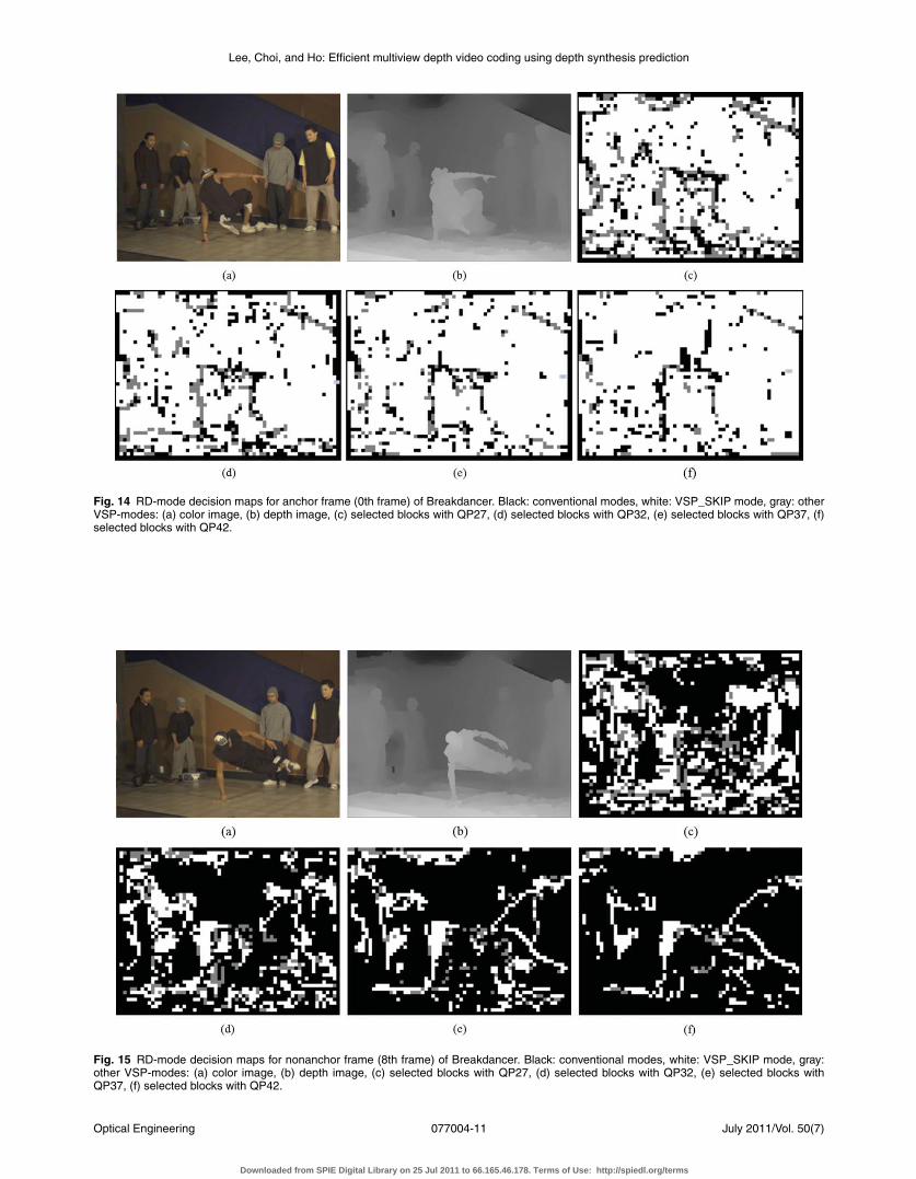
To identify the selected blocks using the VSP modes, wepainted with three colors: black, gray, and white. A whiteblock represents the VSP_SKIP mode and a gray block rep-resents the rest VSP modes such as VSP_16×16, VSP_8×16and so on. The black regions are coded with the conventionalmodes. Figure 14 describes RD-mode decision maps forVSP modes of the first anchor frame; 0th frame of view 1.Figures 14(a) and 14(b) are the original color and depthimages of the first frame, respectively. When we encodedthis depth image with four QPs, we obtained four RD-modedecision maps as shown in Figs. 14(c)–14(f). As the QPincreases, VSP modes were selected more. Similarly, Fig. 15
Table 2 Coding performance for 3-view configuration.
Total views (3 views) B-view (center view) P-view (rightmost view)
Test Data Viewpoints (I-B-P) BDBR (%) BDPSNR (dB) BDBR (%) BDPSNR (dB) BDBR (%) BDPSNR (dB)
Downloaded from SPIE Digital Library on 25 Jul 2011 to 66.165.46.178. Terms of Use: http://spiedl.org/terms
Lee, Choi, and Ho: Efficient multiview depth video coding using depth synthesis prediction
Fig. 14 RD-mode decision maps for anchor frame (0th frame) of Breakdancer. Black: conventional modes, white: VSP_SKIP mode, gray: otherVSP-modes: (a) color image, (b) depth image, (c) selected blocks with QP27, (d) selected blocks with QP32, (e) selected blocks with QP37, (f)selected blocks with QP42.
Fig. 15 RD-mode decision maps for nonanchor frame (8th frame) of Breakdancer. Black: conventional modes, white: VSP_SKIP mode, gray:other VSP-modes: (a) color image, (b) depth image, (c) selected blocks with QP27, (d) selected blocks with QP32, (e) selected blocks withQP37, (f) selected blocks with QP42.
Optical Engineering July 2011/Vol. 50(7)077004-11
Downloaded from SPIE Digital Library on 25 Jul 2011 to 66.165.46.178. Terms of Use: http://spiedl.org/terms
Lee, Choi, and Ho: Efficient multiview depth video coding using depth synthesis prediction
Fig. 16 RD comparison between anchor and nonanchor frames: (a) Breakdancers, (b) Ballet.
Optical Engineering July 2011/Vol. 50(7)077004-12
Downloaded from SPIE Digital Library on 25 Jul 2011 to 66.165.46.178. Terms of Use: http://spiedl.org/terms
Lee, Choi, and Ho: Efficient multiview depth video coding using depth synthesis prediction
describes the RD-mode decision maps for VSP modes ofa nonanchor frame; 8th frame of view 1 at the first GOP.Contrar to the anchor frame case, VSP modes were selectedless as QP increases. It means that the temporal predictionwith the conventional modes has a higher priority to VSPmodes.
Upon this analysis, we noticed that the VSP modes wereselected at the anchor frames more; the improvements ofcoding performance have been achieved by them. To con-firm this, we compared the coding gains between the anchorand nonanchor. Figure 16 describes the RD comparison be-tween the two types of frames. Each RD curve was derivedby averaging both the bitrates and PSNR values with thenumber of frames; the x-axis represents the average bitrates-per-frame. Definitely, the proposed VSP coding method iseffective for the anchor frames.
The proposed VSP coding method was very effective forthe depth data since they have high interview correlationsbetween views. If we can synthesize the current viewpointimage using the reconstructed adjacent view correctly, wecan use them directly without residual data or motion in-formation. This is why the coding gains are raised at theexperiments. However, there are two significant problemson the decoder side. The first problem is a the incensementof the complexity as much as the complexity of the depthsynthesis at the decoder. This problem is a critical problemin the sense of manufacturing, but we expect this complex-ity will be solved by evolutions of technology in the future.Secondary, the proposed VSP coding method employs addi-tional memory for the additional reference frame. Since theproposed method changes the reference buffer managementslightly, we think that assigning additional memory is easyto implement in a future 3D video system.
Note that the proposed VSP coding method exploits thesyntax structure of MVC to indicate the additional predic-tion modes such as VSP_SKIP mode; hence no additionalbits are included. It means that the coding performancewould not drop abruptly even though the quality of the syn-thesized depth map is poor; we can obtain a safe codinggain.
6 ConclusionsIn this paper, we proposed an efficient multiview depth videocoding utilizing the adjacent reference views using the viewsynthesis method. Since the 3D video system involves a mul-tiple viewpoint video, the depth video can use the same pre-diction structure of the multiview video coding. Therefore,some views can refer to the reconstructed views to improvethe coding performance. At first, we synthesize a depth im-age referring to the adjacent reference frame with the 3Dwarping method. We use a pre-processing method to reducean erroneous coding error and two hole filling methods ac-cording to the number of reference view points. In order toexploit the synthesized depth image efficiently, we designedfive additional prediction modes named VSP modes whichrefer to the synthesized frame exclusively. By experiments,we confirmed that the coding efficiency have been improvedsignificantly up to 1.11 dB. Most of the gains are achievedfrom the anchor frames since it has no temporal referenceframes. Although the complexity problem still remains, thisview synthesis prediction method for depth video coding isvery promising for future 3D video systems.
AcknowledgmentsThis work was supported in part by the IT R&D program ofMKE [a development of interactive wide viewing zone SMVoptics of 3D display (10035337)], and in part by the ITRC(Information Technology Research Center) support programsupervised by the NIPA (National IT Industry PromotionAgency) [NIPA-2011-(C1090–1111-0003)].
References1. J. Konrad and M. Halle, “3-D Displays and Signal Process-
ing – An Answer to 3-D Ills?,” IEEE Signal Process. Mag. 24(6),97–111 (2007).
2. L. Onural, A. Smolic, and T. Sikora, “An overview of a new Euro-pean consortium: Integrated three-dimensional television — Capture,transmission and display (3DTV),” presented at the EWIMT, London,(2004).
3. A. Smolic, K. Muller, P. Merkle, C. Fehn, P. Kauff, P. Eiseert,and T. Wiegand, “3-D video and Free Viewpoint Video-Technologies,Applications and MPEG Standards,” in Proc. IEEE ICME, pp. 2161–2164, Canada (2006).
4. A. Smolic, K. Muller, K. Dix, P. Merkle, P. Kauff, and T. Wiegand,“Intermediate view interpolation based on multiview video plus depthfor advanced 3D video systems,” IEEE International Conference onImage Processing (ICIP), pp. 2448–2451, IEEE, San Diego, CA (2008).
5. G. J. Sullivan, T. Wiegand, and H. Schwarz, Eds., “Editors’ DraftRevision to ITU-T Rec. H.264|ISO/IEC 14496 –10 Advanced VideoCoding — in preparation for ITU-T SG 16 AAP Consent (in integratedform),” JVT-AD007 (2009).
6. P. Merkle, A. Smolic, K. Muller, and T. Wiegand, “Efficient PredictionStructures for Multiview Video Coding,” IEEE Trans. Circuits Syst.Video Technol., 17(11), 1461–1473 (2007).
7. E. Martinian, A. Behrens, J. Xin, and A. Vetro, “View synthesis formultiview video compression,” in Proceedings of the Picture CodingSymposium PCS, Beijing, China (2006).
8. S. Yea and A. Vetro, “View synthesis prediction for multiview videocoding,” Signal Processing: Image Commun. 24(1–2), 89–100, IEEE,EURASIP and IET, Lisbon, Portugal (2009).
9. S. Shimizu, M. Kitahara, H. Kimata, K. Kamikura, and Y. Yashima,“View scalable multi-view video coding using 3D warping with depthmap,” IEEE Trans. Circuits Syst. Video Technol. 17(11), 1485–1495(2007).
10. C. Lee, K. J. Oh, and Y. S. Ho, “View interpolation prediction formulti-view video coding,” Proc. PCS 2007, Picture Coding Symposium.(2007).
11. Y. L. Lee, J. H. Hur, Y. K. Lee, K. H. Han, S. Cho, N. Hur, J. Kim,J. H. Kim, P. L. Lai, A. Ortega, Y. Su, P. Yin, and C. Gomila,“CE11: Illumination Compensation,” JVT-U052, Hangzhou, China(2006).
12. H. S. Koo, Y. J. Jeon, and B. M. Jeon, “MVC Motion Skip Mode,”JVT-W081, San Jose, California (2006).
13. J. X. Chai, X. Tong, S. C. Chan, and H. Y. Shum, “Plenoptic sampling,”SIGGRAPH, 307–318 (2000).
14. C. Fehn, “Depth-image-based rendering (DIBR), compression andtransmission for a new approach on 3D-TV,” Proc. SPIE StereoscopicDisplays and Virtual Reality System XI, San Jose, CA (2004).
15. Y. Mori, N. Fukushima, T. Fujii, and M. Tanimoto, “View generationwith 3D warping using depth information for FTV,” Signal Processing:Image Commun. 1–2, 65–72 (2009).
16. L. Zitnick, S. B. Kang, M. Uyttendaele, S. Winder, and R. Szeliski,“High-quality video view interpolation using a layered representation,”SIGGRAPH, 23(3), 600–608 (2004).
17. ISO/IEC JTC1/SC29/WG11, “Draft report on experimental frameworkfor 3D video coding,” MPEG document N11273 (2010).
18. ISO/IEC JTC1/SC29/WG11, “Vision on 3D video,” MPEG documentN10357 (2009).
19. R. Hartley and A. Zisserman, Multiple View Geometry in ComputerVision, 2nd ed., Cambridge University Press (2004).
20. K. J. Oh and Y. S. Ho, “Non-linear bi-directional prediction for depthcoding,” Lect. Notes Comput. Sci. 5879, 522–531 (2009).
21. A. Telea, “An image in painting technique based on the fast marchingmethod,” J. Graphics Tools 9(1), 25–36 (2004).
22. ISO/IEC JTC1/SC29/WG11, “1-D parallel test sequences for MPEG-FTV,” MPEG document M15378 (2008).
23. ISO/IEC JTC1/SC29/WG11, “Philips response to new call for 3DVtest material: Arrive book & mobile,” MPEG document M16419(2009).
24. ISO/IEC JTC1/SC29/WG11, “Description of exploration experimentsin 3D video coding,” MPEG document N11477 (2010).
25. G. Bjontegaard, “Calculation of average PSNR differences betweenRD-curves,” Doc. VCEG-M33 (2001).
Optical Engineering July 2011/Vol. 50(7)077004-13
Downloaded from SPIE Digital Library on 25 Jul 2011 to 66.165.46.178. Terms of Use: http://spiedl.org/terms
Lee, Choi, and Ho: Efficient multiview depth video coding using depth synthesis prediction
Cheon Lee received his BS degree in elec-tronic engineering and avionics from KoreaAerospace University (KAU), Korea, in 2005and an MS degree in information and com-munication engineering at the Gwangju In-stitute of Science and Technology (GIST),Korea, in 2007. He is currently working to-ward his PhD degree in the Information andCommunications Department at GIST, Ko-rea. His research interests include digital sig-nal processing, video coding, 3D video cod-
ing, depth estimation, 3D television and realistic broadcasting.
Byeongho Choi received the B.S and M.Sdegrees in Electronic engineering from theUniversity of Hanyang, Republic of Korea, in1991 and 1993, respectively, and PhD de-gree in Department of Image Engineeringfrom the University of Chungang, Republicof Korea, in 2010. From 1993 to 1997, hehad worked for LG Electronics Co. Ltd asa junior researcher. In 1997, he joined Ko-rea Electronics Technology Institute (KETI),where he was involved in the development
of multi-view video, stereo vision and other video systems. He iscurrently a Managerial Researcher of SoC Research Center. His re-search interests include digital image processing, and its application,especially such as 3DTV, stereo vision system.
Yo-Sung Ho received both BS and MS de-grees in electronics engineering from SeoulNational University, Korea, in 1981 and 1983,respectively, and a PhD degree in electricaland computer engineering from the Univer-sity of California, Santa Barbara, in 1990.He joined the Electronics and Telecommu-nications Research Institute (ETRI), Korea,in 1983. From 1990 to 1993, he was withPhilips Laboratories, Briarcliff Manor, NewYork, where he was involved in the devel-
opment of the advanced digital high-definition television (AD-HDTV)system. In 1993, he rejoined the technical staff of ETRI and wasinvolved in the development of the Korea direct broadcast satellite(DBS) digital television and high-definition television systems. Since1995, he has been with the Gwangju Institute of Science and Technol-ogy (GIST), where he is currently a professor in the Information andCommunications Department. Since 2003, he has also been directorof Realistic Broadcasting Research Center (RBRC) at GIST in Korea.His research interests include digital image and video coding, imageanalysis and image restoration, advanced coding techniques, digitalvideo and audio broadcasting, 3D television, and realistic broadcast-ing.
Optical Engineering July 2011/Vol. 50(7)077004-14
Downloaded from SPIE Digital Library on 25 Jul 2011 to 66.165.46.178. Terms of Use: http://spiedl.org/terms