EFFECT OF AMBIENT TEMPERATURE ON THE PERFORMANCE OF COMBINED CYCLE POWER PLANT WITH COOLING SYSTEM IN A SUBTROPICAL REGION HAYDER BAQER MAHDI Thesis submitted in partial fulfilment of the requirements For the award of the degree of Master of Engineering (Mechanical Engineering) FACULTY OF MECHANICAL ENGINEERING UNIVERSITI MALAYSIA PAHANG February 2016
Transcript
EFFECT OF AMBIENT TEMPERATURE ON THE PERFORMANCE OF
COMBINED CYCLE POWER PLANT WITH COOLING SYSTEM IN A
SUBTROPICAL REGION
HAYDER BAQER MAHDI
Thesis submitted in partial fulfilment of the requirements
For the award of the degree of
Master of Engineering (Mechanical Engineering)
FACULTY OF MECHANICAL ENGINEERING
UNIVERSITI MALAYSIA PAHANG
February 2016
vi
ABSTRACT
The climate conditions have a powerful influence on combined cycle power plant
performance as its known. Total output power and overall thermal efficiency of the
power plant dropping under the high ambient temperatures that often occur during the
hot days. This is a major drawback for combined cycle power plant operated in a
subtropical region. In the Middle East where this study was carried out, the ambient
temperature typically varies between (15C) and (45C). The Plant has been studied
consist of three gas turbines with total power (535MW) and three triple-pressure heat
recovery steam generators, addition one steam turbine with (345 MW) output power.
The overall thermal efficiency of power plant is (57.7%). In this study, combined cycle
power plant was used for assessment of the performance with the changes in ambient air
temperature. Two approaches were used to study this phenomenon. Firstly, the
performance parameters were calculated by using actual data acquired by the operation
history of the power plant. Secondly, the performance was analyzed using
thermodynamic principles. Then results of the two approaches were compared and
optimizing using RBFNN method. Cooling the gas turbine inlet air can improve the
power plant performance substantially. This occurs due to the cooled air is denser,
giving the compressor a higher mass flow rate and resulting in increased output power
and efficiency of the power plant. Single effect LiBr absorption chiller proposed as a
cooling system to cool the ambient air temperature at (15 C). The average reduction in
power output per degree Celsius is about (1.82 MW). Cooling of inlet air from (45°C)
down to (15°C) would increase the power output around (50.04MW). Where every
decline in temperature by (10°C) adding to the total output power of (16 MW). The
average reduction in the overall thermal efficiency per degree Celsius is about
(0.217%). In addition, the cooling of inlet air from (45°C) down to (15°C) would
increase the overall thermal efficiency around (6.091%). Where every decline in the
temperature by (10°C), that increases the overall thermal efficiency around (2.03%).
The results of using this cooling technique are increasing the total output power and
overall thermal efficiency to (875 MW), (58%) respectively. The effect of using radial
basis function neural network (RBFNN) technique give the average deviation about
(1.2%) and (1.7%) for the power output and thermal efficiency respectively.
vii
ABSTRAK
Keadaan iklim mempunyai pengaruh yang kuat ke atas gabungan prestasi loji janakuasa
kitar seperti yang diketahui. Jumlah kuasa output dan kecekapan keseluruhan haba loji
kuasa menjatuhkan bawah suhu ambien yang tinggi yang sering berlaku pada hari-hari
panas. Ini adalah kelemahan utama bagi loji tenaga kitaran beroperasi di kawasan yang
subtropika. Di Timur Tengah di mana kajian ini dijalankan, suhu ambien biasanya
berbeza-beza antara (15C) dan (45C). Loji telah dikaji terdiri daripada tiga turbin gas
dengan jumlah kuasa (535 MW) dan tiga penjana pemulihan haba wap tekanan tiga kali
ganda, tambahan satu turbin stim dengan (345 MW) kuasa keluaran. Kecekapan
keseluruhan haba loji kuasa (57.7%). Dalam kajian ini, loji tenaga kitaran telah
digunakan untuk penilaian prestasi dengan perubahan dalam suhu udara ambien. Dua
pendekatan telah digunakan untuk mengkaji fenomena ini. Pertama, parameter prestasi
dikira dengan menggunakan data sebenar yang diperolehi oleh sejarah operasi loji
janakuasa. Kedua, prestasi dianalisis menggunakan prinsip termodinamik. Maka
keputusan kedua-dua pendekatan telah dibandingkan dan mengoptimumkan
menggunakan kaedah RBFNN. Penyejukan udara masuk turbin gas boleh meningkatkan
prestasi loji kuasa dengan ketara. Ini berlaku kerana udara sejuk adalah lebih padat,
memberikan pemampat kadar aliran jisim yang lebih tinggi dan menyebabkan
peningkatan kuasa keluaran dan kecekapan loji kuasa. Single kesan LIBR penyejuk
penyerapan dicadangkan sebagai sistem penyejukan untuk menyejukkan suhu udara
ambien di (15 C). Pengurangan purata kuasa output per darjah Celsius adalah kira-kira
(1.82 MW). Penyejukan udara masuk dari (45 ° C) ke (15 ° C) akan meningkatkan
output kuasa sekitar (50.04MW). Di mana setiap penurunan suhu dengan (10 ° C)
menambah kepada jumlah kuasa keluaran (16 MW). Pengurangan purata kecekapan
haba keseluruhan per darjah Celsius adalah kira-kira (0,217%). Di samping itu,
penyejukan udara masuk dari (45 ° C) ke (15 ° C) akan meningkatkan kecekapan
keseluruhan haba sekitar (6,091%). Di mana setiap penurunan suhu oleh (10 ° C), yang
meningkatkan kecekapan keseluruhan haba sekitar (2.03%). Keputusan menggunakan
teknik ini penyejukan semakin meningkat jumlah kuasa keluaran dan kecekapan haba
keseluruhan (875 MW), (58%) masing-masing. Kesan penggunaan rangkaian neural
teknik jejarian fungsi asas (RBFNN) memberi sisihan purata kira-kira (1.2%) dan
(1.7%) untuk output kuasa dan kecekapan haba masing-masing.
viii
CONTENTS
Page
SUPERVISORS' DECLARATION ii
STUDENT'S DECLARATION iii
ACKNOWLEDGEMENTS v
ABSTRACT vi
ABSTRAK vii
CONTENTS viii
LIST OF TABLES xi
LIST OF FIGURES xi
NOMENCLATURES xiv
LIST OF ABBREVIATIONS xvii
CHAPTER I INTRODUCTION
1.1 Introduction 1
1.2 Problem Statement 5
1.3 Objectives of the Study 6
1.4 Methodology 6
1.5 Scope of the Study 7
1.6 Thesis Outline 8
CHAPTER II LITERATURE REVIEW
2.1 Introduction 9
2.2 Ambient Temperature Effect 9
2.3 Background and Past Work 11
2.4 Economic Criteria for Inlet Cooling 16
2.5 Methods of Cooling the Inlet Air for Gas Turbine in Combined
Cycle Power Plants
17
2.5.1 Water Evaporation Systems 18
2.5.2 Evaporative Cooler 18
2.5.3 Evaporative Cooling of Pre-Compressed Air 21
2.5.4 Fogging System 22
ix
2.5.5 Heat Transfer Systems 25
2.5.6 Mechanical Refrigeration System with Chilled Water
Storage
25
2.5.7 Mechanical Refrigeration System with Ice Storage 27
2.5.8 Lithium-Bromide Absorption Chiller 29
2.6 Summary 35
CHAPTER III METHODOLOGY
3.1 Introduction 36
3.2 Power Plant Description 36
3.3 Strategy Of Work Frame 37
3.4 Thermodynamic Approach on the Combined Cycle 38
3.4.1 Ideal Brayton Cycle
38
3.4.2 Modelling of Actual Gas Turbine Cycle
40
3.4.3 Ideal Rankine Cycle
45
3.4.4 Heat Recovery Steam Generator (HRSG 47
3.4.5 Steam Turbine 55
3.5 Modelling of Cooling Cycle System (Single-Effect Libr-Water
Absorption Chiller)
57
3.5.1 Air Heat Exchanger
60
3.5.2 Evaporator
61
3.5.3 Expansion Valve
62
3.5.4 Condenser
62
3.5.5 Solution Heat Exchanger 63
3.5.6 Generator
64
3.5.7 Absorber
64
3.5.8 Pump
65
3.5.9 Throttle Valve 66
3.6 Optimization Technique 66
3.6.1 RFBNN Optimization Technique 67
3.6.2 RBFNN Structure
67
3.7 Summary 69
x
CHAPTER IV RESULTS AND DISCUSSION
4.1 Introduction 70
4.2 Analysis the Ambient Temperature Effect 70
4.3 Analysis the Cooling System Results 80
4.4 Optimization Results 87
4.5 Summary 89
CHAPTER V CONCLUSIONS AND RECOMMENDATIONS
5.1 Introduction 90
5.2 Total Output Power of Power Plant 90
5.3 Overall Thermal Efficiency of Power Plant 91
5.4 Specific Fuel Consumption 92
5.5 Recommendations for Future Work 92
REFERENCES 93
APPENDIX
A MATLAB Codes for RBFNN Optimization Technique 99
xi
LIST OF TABLES
Table No. Title Page
2.1 Analysis of variance (ANOVA) results of the GT plant
13
LIST OF FIGURES
Figure No. Title Page
1.1 World marketed energy consumption, 1990-2035.
2
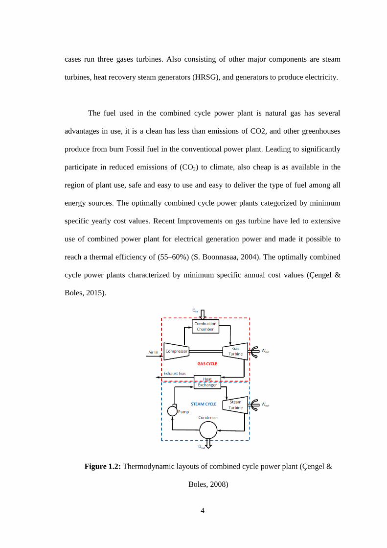
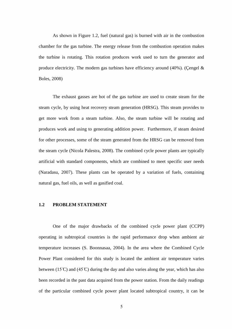
1.2 Thermodynamic layouts of combined cycle power plant
(Çengel & Boles, 2008)
4
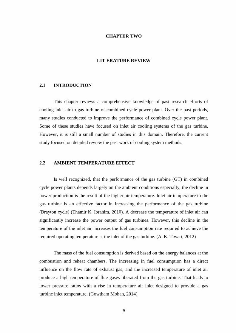
2.1
Annual variation in power production, rate of fuel, intake air
and exhaust gas parameters in gas cycle (Gowtham Mohan,
2014)
11
2.2 Design characteristics with inlet air temperature of gas turbine
(Omidvar, 2001)
12
2.3 Schematic of evaporative air cooling with optimal water
treatment (Hosseini, et al., 2007)
20
2.4 Direct evaporative panel (a) schematic diagram (b) panel
control volume (Marcos. B, 2005)
21
2.5 High pressure fogging skid in operation for gas turbine 23
2.6 Fogging nozzle (Mee, Thomas, 1999) 23
2.7 Fogging system (Isratec engineering and investment Ltd) 24
2.8 Schematic of mechanical chiller with chilled water storage 26
2.9 Schematic of mechanical chilled with ice storage system 29
2.10 Schematic of absorption chiller inlet air cooling system
30
xii
3.1 Strategy of the work frame for the current research
methodology
37
3.2 Thermodynamic states of the Brayton cycle (Brayton Energy,
n.d.)
38
3.3 Internal components of the gas turbine (Kawasaki Gas Turbine,
n.d)
41
3.4 The graphical diagram for s Gas Turbine 41
3.5 Temperature-entropy graph for actual Gas Turbine cycle 42
3.6 Thermodynamic states of Rankine cycle (Stine& Geyer 2004) 45
3.7 CCPP diagram with triple-pressure heat recovery steam
generator (HRSG) 48
3.8 Diagram for typical temperature heat transfer of triple-pressure-
reheat HRSG
50
3.9 Combined Cycle Power Plant with Cooling System 58
3.10 Single effect Absorption chiller diagram 60
3.11 Radial Basis Function Neural Network (RBFNN) structure
(Xin-zheng XU 2011)
67
4.1 Variations of the temperature during a typical day of months for
one year (2011)
71
4.2 Variations of the temperature during a typical day of five
months
72
4.3 Variations of the temperature during the seasons of the year
2011
73
4.4 Variations in total power with ambient temperatures 73
4.5 Variations in the overall thermal efficiency with ambient
temperatures
74
4.6 Variations of total power with ambient temperatures for model
and actual data
76
4.7 Variations in the overall thermal efficiency with ambient
temperatures for model and actual data
76
4.8 Effect of ambient temperature on specific fuel consumption 77
xiii
4.9 Effect of ambient temperature on exhaust heat energy outlet
from gas turbine
78
4.10 Effect of ambient temperature on exhaust heat energy of GTand
Power to heat energy ratio
79
4.11 Variation of COP with the generator temperature of the
absorption chiller at different evaporator temperatures
81
4.12 Variation of COP and heat energy of evaporator for an
absorption chiller with the different ambient air temperatures
82
4.13 Variations of total power with ambient temperatures for model,
actual data and with using cooling system
83
4.14 Variations of total power in one typical day of actual data for
seasons and with using cooling system
84
4.15 Variations of overall thermal efficiency with ambient
temperatures for model, actual data and with using cooling
system
85
4.16 Variations of the overall thermal efficiency in one typical day
of actual data for seasons and with using cooling system
86
4.17 Comparison total output power calculated from thermodynamic
model and actual data of CCPP using RBFNN
88
4.18 Comparison overall thermal efficiency calculated from
thermodynamic model and actual data of CCPP using RBFNN
88
xiv
NOMENCLATURES
List of Symbols
Symbol Meaning and units
AFR Air-fuel ratio
Cpa The specific heat of the air (kJ/kg.K)
Cpf The specific heat of the fuel (kJ/kg.K)
Cpg The specific heat of flue gas (kJ/kg.K)
f The fuel-air ratio
h Enthalpy (kJ/kg)
h4f The heat loss factor in the heat recovery steam generator
LHV The lower heating value (kJ/kg)
am The air mass flow rate (kg/s)
fm
The fuel mass flow rate (kg/s)
gm The mass flow rate of the exhaust gases through the gas turbine (kg/s)
P The net power output of the turbine (MW)
p Pressure (bar)
p1 Compressor inlet pressure (bar)
p2 Compressor outlet air pressure (bar)
The heat supplied (kJ/kg)
The heat available with exhaust gases from gas turbine cycle (kJ/kg)
Heat rejected from condenser (kJ/kg)
rp Pressure ratio
Heat of exhaust gases (kJ/kg)
SFC The specific fuel consumption (kg/kW.h)
T Temperature (K)
T1 Compressor inlet air temperature (K)
T2 Compressor outlet air temperature (K)
T2s The isentropic temperature of outlet compressor (K).
xv
Ta The average temperature (T2+T1)/2 (K)
Tap The approach points (K)
Tf The temperature of fuel (K)
Tpp The pinch point (K)
Ts The saturation steam temperature (K)
Tw1 The temperature of water entering the economizer (K)
Tw2 The temperature of water entering the evaporator (K)
vf Specific volume of the water (m3/kg)
Wcomp The work of the compressor (kJ/kg)
WGTnet The net work of the gas turbine (kJ/kg)
Wpump The work of the pump (kJ/kg)
WSTnet The work net of the steam turbine cycle (kJ/kg)
W The work of the steam turbine (kJ/kg)
WST The shaft work of the turbine (kJ/kg)
Greek Symbols
Symbol Meaning
ε Effectiveness of the regenerative heat exchanger
ρ Density (kg/m3)
k Specific heat ratio
Specific heat ratio of air
Specific heat ratio of gases
Efficiency
Isentropic compressor efficiency
chp The high-pressure compressor efficiency
clp The low-pressure compressor efficiency
HPT The high-pressure turbine efficiency
LPT The low-pressure turbine efficiency
The mechanical efficiency of the compressor and turbine
p The water pump efficiency
xvi
The steam turbine efficiency
Overall efficiency of CCPP
Thermal Brayton cycle efficiency
th The thermal efficiency of the gas turbine
Subscripts
Symbol Meaning
1,2…etc State number
a Air
add Added
ap Approach point
av Average
comp Compressor
cond Condenser
f Fuel
g Gases
GTnet Gas turbine net work
HP High pressure
IP Intermediate pressure
LP Low pressure
p pump
pp Pinch point
s Saturated steam
STnet Steam turbine work net
ss Superheated steam
ST Steam turbine
w Water
w1 Inlet water to economizer
w2 Inlet water to evaporator
xvii
LIST OF ABBREVIATIONS
Comp Compressor
C.C Combustion chamber
CCPP Combined cycle gas turbine power plant
D Drum
GT Gas turbine
HE Heat exchanger
HPST High pressure turbine
HRSG Heat recovery steam generator
IEA International Energy Agency
IP Intermediate pressure
IPST Intermediate pressure turbine
ISO International standards organization
LHV Lower Heating Value
LP low pressure
LPST Low pressure turbine
SFC Specific fuel consumption
ST Steam turbine
TIT Turbine inlet temperature
1
CHAPTER ONE
INTRODUCTION
1.1 INTRODUCTIONS
When the industrial revolution is starting, people become more and more
dependent on hydrocarbon fuels for the generation of power. Now around (85%) of the
energy requirements of the almost counties are supplied by fossil fuels. The increasing
combustion of fossil fuels and associated carbon dioxide (CO2) emissions are creating
concerns about climate change. One of the most significant and innovative solutions
that reduce greenhouse gas emissions and an increase in generated net power with
characterized as high efficiency is a combined cycle power plant (CCPP).
Grows energy consumption of the world marketed by (49) percent from (2007 to
2035) (IEO, 2010). The total energy use in the world rises from (495) quadrillions
British thermal units (Btu) in (2007) to (590) quadrillions Btu in (2020) and (739)
quadrillions Btu in (2035) as shown in Figure 1.1 (IEO, 2010) an increase of over (6%)
per annum (Sepehr Sanjay, 2011). The global economic downturn which started in
(2007) and non-stop until (2015) has had a profound shock on world energy
requirement in the near expression. With the fall in demand among both manufacturers
and consumers came a decline in total global marketed energy consumption by (1.2)
percent in (2008) and by (2.2) percent in (2009) (IEO, 2010).
2
The average annual growth in electricity power demand in the world, over the
past twenty years, was approximately 6 % and forecast for the next five years is 6% per
annum (Marroquin, 2010). Furthermore, the rate of electricity consumption was
observed to be higher than the rate of production and in particular during the summer
season where the high peak of electricity demand prevails.
Fig 1.1: World marketed energy consumption, 1990-2035.
International Energy Outlook (IEO), 2010. U.S. Energy Information Administration,
(http://www.eia.doe.gov/oiaf/ieo/world.html).
Due to The combined cycle power plant flexibility in the production of power
and relatively inexpensive capital costs, in recent years, it becomes more popular used.
This flexibility in the application of combined cycle and improved efficiencies can be
achieved. This flexibility is imperative (D. Mahto, 2012). Through the design of the
cycle, can operating the gas turbine without operation of the steam turbine.
Additionally, parts of the steam that generated from the Heat Recovery Steam
Generator (HRSG) can be used for other processes like cooling by vapor absorption