UNCLASSIFIED UNCLASSIFIED Effect of Explosion Bulge Test Parameters on the Measurement of Deformation Resistance for Steel C. H. Choi 1 , M. Callaghan 2 and B. Dixon 1 1 Defence Science and Technology Organisation 2 University of Manchester DSTO-TN-1263 ABSTRACT This paper investigates the effects of varying some of the explosion bulge test conditions on assessment of the plate deformation resistance (bulge depth and plate thinning), focusing on four parameters: (a) use of cardboard wrapping to provide thermal insulation for the test plate prior to blasting (b) changing the means of supporting the charge above the plate from a cardboard box enclosure to a suspended stocking, (c) effect of testing temperature, and (d) the effect of crack starter weld beads on plate deformation. Of the four parameters, it was found that the use of a cardboard box enclosure provides measurably different outcomes compared to a charge suspended from the ceiling by a stocking. Approved for Public Release RELEASE LIMITATION
Transcript
UNCLASSIFIED
UNCLASSIFIED
Effect of Explosion Bulge Test Parameters on the Measurement of Deformation Resistance for Steel
C. H. Choi1, M. Callaghan2 and B. Dixon1
1Defence Science and Technology Organisation 2University of Manchester
DSTO-TN-1263
ABSTRACT This paper investigates the effects of varying some of the explosion bulge test conditions on assessment of the plate deformation resistance (bulge depth and plate thinning), focusing on four parameters: (a) use of cardboard wrapping to provide thermal insulation for the test plate prior to blasting (b) changing the means of supporting the charge above the plate from a cardboard box enclosure to a suspended stocking, (c) effect of testing temperature, and (d) the effect of crack starter weld beads on plate deformation. Of the four parameters, it was found that the use of a cardboard box enclosure provides measurably different outcomes compared to a charge suspended from the ceiling by a stocking.
Effect of Explosion Bulge Test Parameters on the Measurement of Deformation Resistance for Steel
Executive Summary
The Explosion Bulge Test has been used for over 60 years as a standard test for the assessment of steel toughness and deformation resistance under blast loading conditions [1-3]. However, details of the test conditions vary considerably from one country to the other. For example, the Australian test is almost identical to that used in the USA, while in the UK and Germany the test is conducted under water and hence test conditions are substantially different. This paper investigates the effects of varying some of the test conditions and assessing the ultimate test outcomes, focusing on four parameters: (a) use of cardboard wrapping to provide thermal insulation for the test plate prior to blasting; (b) changing the means of supporting the charge above the plate from a cardboard box enclosure to a charge held in a stocking and suspended from the ceiling; (c) effect of temperature; and (d) the effect of crack starter beads on plate deformation. Of the four parameters evaluated in this study, it was found that replacement of the cardboard box enclosure with a charge suspended over the test plate may produce differing bulge depth results. The other parameters have no measurable influence. It is concluded that use of the cardboard box enclosure for supporting a charge of the Explosive Bulge Test should not be varied.
UNCLASSIFIED
UNCLASSIFIED
This page is intentionally blank
UNCLASSIFIED
UNCLASSIFIED
Authors
Chang-Ho Choi Defence Science and Technology Organisation Chang-Ho Choi obtained a Master’s degree in Materials Science at the University of Oregon and undertook PhD study at the University of Illinois and later at the University of New South Wales, where he received a PhD with a thesis on superconductors. He has been employed as a materials scientist at DSTO Maritime Platforms Division since 1998. During the period 1998 to 2006, he worked with the metallurgy section. From 2006 to 2009, he worked in the biology section and from 2009 onward, in the Armour Mechanics and Vehicle Survivability group of Land Division.
Mark Callaghan The University of Manchester Mark Callaghan undertook his PhD at ANSTO, researching high temperature fatigue behaviour and modelling of ferritic pressure vessel steel, for which he was awarded the degree at the University of Technology, Sydney in 2009. He joined the University of Wollongong in 2008 as a Research Fellow, where he undertook research into armour and high strength steels subjected to static and dynamic loadings, weldability and welding metallurgy of these materials as a function of welding processes and simulations. In 2012, Mark was appointed as Research Associate at The University of Manchester, researching thick-walled corrosion resistant materials for high-temperature high-pressure service.
Brian Dixon Defence Science and Technology Organisation Brian Dixon is a metallurgy scientist in the Maritime Platforms Division of Defence Science and Technology Organisation. He has been employed at DSTO since 1978, undertaking experimental development and fundamental studies into weld metal solidification cracking in steels and stainless steels. He has also undertaken extensive work on improving the weld zone toughness of high strength steels. During 1989 and 1990 Brian worked at Kockums Laboratory in Sweden as part of DSTO's contribution to the submarine project. Since 2001, Brian has worked in a number of developmental positions, including Director, Program Office (Maritime), STCC for M1 and M6 and S&T Adviser for JP 2048. He is currently head of the Armour Mechanics and Vehicle Survivability Group.
BD Bulge depth CBW Cardboard wrap as insulation to maintain required plate test temperature CBE Cardboard box enclosure for 320 mm distance between plate and charge CCD Charge cylinder diameter CW Crack starter NCW No crack starter weld bead
UNCLASSIFIED DSTO-TN-1263
UNCLASSIFIED 1
1. Introduction
Faced with a broad range of conventional and home-made weapons, modern armoured vehicles and associated equipment need effective armour protection. For steel armour, the mechanical properties that are most influential in protective performance are hardness, strength, ductility, and toughness (see [4-12]). A second consideration is the weight, which influences performance and manoeuvrability, operating costs and maintenance requirements of up-armoured vehicles. The armour industries have identified a number of candidate materials to protect and reduce the weight of armour vehicles [13-18]. These candidate materials require qualification, in terms of metallurgical and structural integrity analyses, as well as ballistic and blast performance before informed decisions can be made for potential utilisation of these materials into armoured vehicles. The Explosive Bulge Test (EBT) has been used for a number of years to characterize the toughness, deformation resistance and dynamic plasticity of structural and armour materials subjected to rapid loading under the blast regime. DSTO has undertaken a number of explosive bulge tests to characterize and analyse candidate amour materials, as reported in [4]. Following [4], a number of test parameters were identified that may influence test results. These include: test temperature; use of cardboard wrapping to maintain plate temperature; use of a crack starter weld bead to evaluate deformation resistance of the steel plate; and two methods to suspend the explosive charge at a height above the flyer plate. Some of these parameters directly influence the time and costs required when undertaking the EBT and may have implications for safety when conducting the test. The purpose of this investigation was to assess the effects of these parameters on the material performance when subjected to explosive blast loading. It is essential that the effects of these parameters be well understood and hence characterized, before considering any possible changes to the EBT procedure in order to ensure that new results are directly comparable with those results previously determined in past studies.
2. Experiments
2.1 Explosion Bulge Tests
In this investigation, the EBT was carried out at ambient (AMT) temperature and -18 °C. Deformation resistance of the plate was measured in terms of both bulge depth and thinning at the plate centre. A series of EBTs were performed on Grade 350 mild steel plate possessing thicknesses of 3 to 10 mm using a charge weight (PE4 high explosive) of 0.46 kg. The charge shape was cylindrical, with diameters of 100 mm and 160 mm.
UNCLASSIFIED DSTO-TN-1263
UNCLASSIFIED 2
Before testing, each test plate was plasma-cut to dimensions of 760 mm x 760 mm to match the dimensions of the die block. Plates for EBT were prepared with a crack starter weld beads, 50 mm long and 10 mm wide, oriented along the plate rolling direction (Figure 1). These weld beads are composed of hard facing material that is inherently brittle and, under blast loading, act as a crack starter to force the initiation of brittle cracking in the weld zone and subsequently into the parent plate. Resistance to cracking is related to the toughness of the plate material. The plate was clamped with a bolted shackle in order to avoid the blasted plates impacting the ceiling of the blast chamber. To enable clamping, holes were drilled in two opposing corners of each plate. For the plates to be tested at -18 °C (the standard test temperature for the EBT), a type ‘k’ thermocouple was spot-welded to the topside of the plate to ensure correct temperatures were achieved prior to testing. The plates were conditioned at approximately -40 ºC and left to equilibrate overnight before testing. The thermocouple was then connected to a NI 9213 Module with 16 channels and 24 Bit thermocouple inputs from National Instruments (NI). The NI module was then connected to the NI cDAQ 9172 chassis, which was in turn connected to a notebook computer by a USB port. A schematic of the test plate is shown in Figure 1, identifying the location of the crack starter weld beads, blast chamber, thermocouple and clamp positions.
(a ) (b)
(c) (d)
Figure 1: (a) weld bead on the centre of the plate (arrowed) (b) view of the blast chamber, (c) thermocouple position on the edge of the test plate and (d) the schematic sketch.
Crack starter
Crack starter weld
Clamp position
Clamp position
Thermo couple
UNCLASSIFIED DSTO-TN-1263
UNCLASSIFIED 3
The plate thinning was measured as shown in Figure 2(a) at 6 points. Thickness was measured at two points on the edge of the plate (A) and four points in the centre (B) where deformation was greatest. The bulge depth was measured from the flat surface of the plate to the maximum bulge of the plate after a blast (Figure 2b). The percentage thinning was estimated by the formula ((average A-average B)/average A). The average error tolerance of the bulge depth measurement was maximum ± 8.3%. The error tolerance of the measurement was max 8%. (a) (b)
Figure 2: (a) Schematic diagram of the 6 point system of measurement for plate thinning percentage measurement system. The position of the crack starter weld bead is also shown; (b) schematic bulge depth measurement. The bulge depth measurement is measured along the yellow line from the green line to the point of maximum bulge height.
2.2 Test Parameters
Test parameters in this program of work are summarized below:
Cardboard insulation In the recent tests, some of the target plates were wrapped with cardboard for insulation during transport from the temperature-conditioning chamber to the blast chamber. The testing was then undertaken with the cardboard in place. This differs from previous practice where plates were not covered during testing. In the current tests, the bulge depth and thinning of the test plates with and without cardboard wrapping (CBW) were measured to see if this parameter is significant in the material blast resistance.
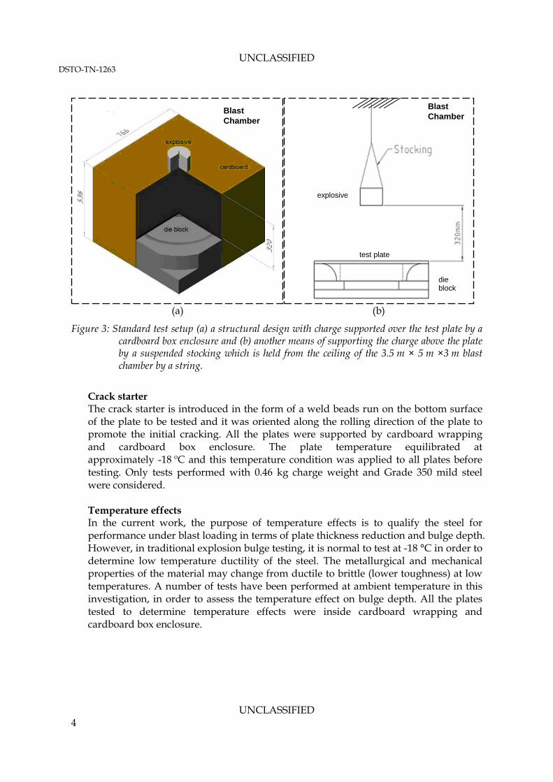
Replacement of cardboard box with suspended charge Figure 3a shows the test setup in which the die block is covered with a cardboard box enclosure (CBE) to maintain a 320 mm standoff from the bottom of explosive charge to the top of the target plate. In the tests reported here, an alternate setup was used in which the charge was suspended from the chamber ceiling as shown in Figure 3b.
Crack starter weld bead
A A
B
B
B
B
UNCLASSIFIED DSTO-TN-1263
UNCLASSIFIED 4
(a) (b)
Figure 3: Standard test setup (a) a structural design with charge supported over the test plate by a cardboard box enclosure and (b) another means of supporting the charge above the plate by a suspended stocking which is held from the ceiling of the 3.5 m × 5 m ×3 m blast chamber by a string.
Crack starter The crack starter is introduced in the form of a weld beads run on the bottom surface of the plate to be tested and it was oriented along the rolling direction of the plate to promote the initial cracking. All the plates were supported by cardboard wrapping and cardboard box enclosure. The plate temperature equilibrated at approximately -18 ºC and this temperature condition was applied to all plates before testing. Only tests performed with 0.46 kg charge weight and Grade 350 mild steel were considered. Temperature effects In the current work, the purpose of temperature effects is to qualify the steel for performance under blast loading in terms of plate thickness reduction and bulge depth. However, in traditional explosion bulge testing, it is normal to test at -18 °C in order to determine low temperature ductility of the steel. The metallurgical and mechanical properties of the material may change from ductile to brittle (lower toughness) at low temperatures. A number of tests have been performed at ambient temperature in this investigation, in order to assess the temperature effect on bulge depth. All the plates tested to determine temperature effects were inside cardboard wrapping and cardboard box enclosure.
Blast Chamber
test plate
explosive
die block
Blast Chamber
UNCLASSIFIED DSTO-TN-1263
UNCLASSIFIED 5
3. Results and Discussion
This section reports on the experimental results and provides analyses of the EBT conducted on 350 grade mild steel plate material as a function of the four test parameters described in Section 2, as well as detailing the effects of these parameters on bulge depth. 3.1 Crack Starter Effects
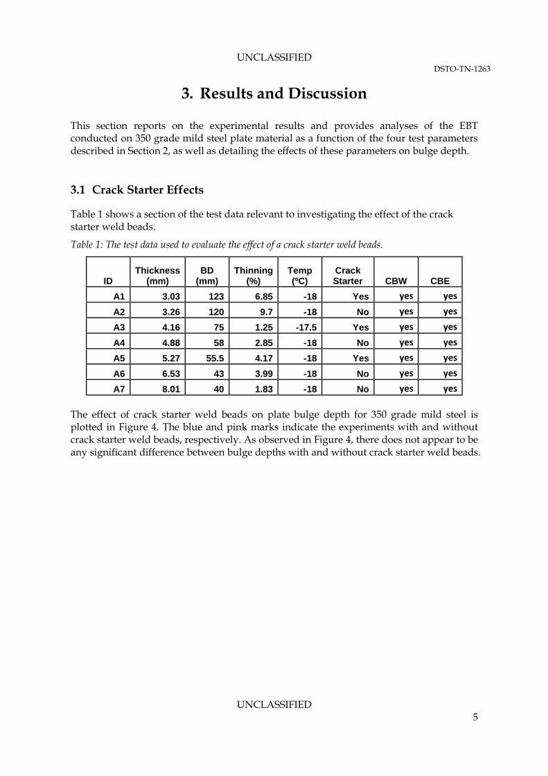
Table 1 shows a section of the test data relevant to investigating the effect of the crack starter weld beads.
Table 1: The test data used to evaluate the effect of a crack starter weld beads.
A6 6.53 43 3.99 -18 No yes yes A7 8.01 40 1.83 -18 No yes yes
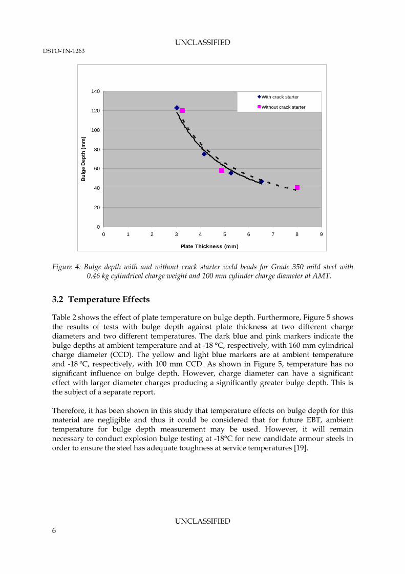
The effect of crack starter weld beads on plate bulge depth for 350 grade mild steel is plotted in Figure 4. The blue and pink marks indicate the experiments with and without crack starter weld beads, respectively. As observed in Figure 4, there does not appear to be any significant difference between bulge depths with and without crack starter weld beads.
UNCLASSIFIED DSTO-TN-1263
UNCLASSIFIED 6
0
20
40
60
80
100
120
140
0 1 2 3 4 5 6 7 8 9
Plate Thickness (mm)
Bul
ge D
epth
(mm
)
With crack starter
Without crack starter
Figure 4: Bulge depth with and without crack starter weld beads for Grade 350 mild steel with 0.46 kg cylindrical charge weight and 100 mm cylinder charge diameter at AMT.
3.2 Temperature Effects
Table 2 shows the effect of plate temperature on bulge depth. Furthermore, Figure 5 shows the results of tests with bulge depth against plate thickness at two different charge diameters and two different temperatures. The dark blue and pink markers indicate the bulge depths at ambient temperature and at -18 °C, respectively, with 160 mm cylindrical charge diameter (CCD). The yellow and light blue markers are at ambient temperature and -18 ºC, respectively, with 100 mm CCD. As shown in Figure 5, temperature has no significant influence on bulge depth. However, charge diameter can have a significant effect with larger diameter charges producing a significantly greater bulge depth. This is the subject of a separate report. Therefore, it has been shown in this study that temperature effects on bulge depth for this material are negligible and thus it could be considered that for future EBT, ambient temperature for bulge depth measurement may be used. However, it will remain necessary to conduct explosion bulge testing at -18°C for new candidate armour steels in order to ensure the steel has adequate toughness at service temperatures [19].
UNCLASSIFIED DSTO-TN-1263
UNCLASSIFIED 7
Table 2: The test data used to evaluate the temperature effects. All the blast tests were performed with CBE.
Figure 5: Bulge depth of Grade 350 mild steel at two different blast temperatures and charge
diameters. Refer to Table 3.
UNCLASSIFIED DSTO-TN-1263
UNCLASSIFIED 8
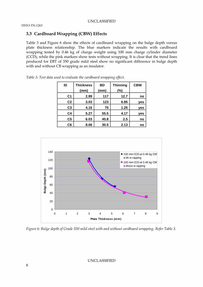
3.3 Cardboard Wrapping (CBW) Effects
Table 3 and Figure 6 show the effects of cardboard wrapping on the bulge depth versus plate thickness relationship. The blue markers indicate the results with cardboard wrapping tested by 0.46 kg of charge weight using 100 mm charge cylinder diameter (CCD), while the pink markers show tests without wrapping. It is clear that the trend lines produced for EBT of 350 grade mild steel show no significant difference in bulge depth with and without CB wrapping as an insulator.
Table 3: Test data used to evaluate the cardboard wrapping effect.
ID Thickness BD Thinning CBW (mm) (mm) (%)
C1 2.99 117 12.7 no C2 3.03 123 6.85 yes C3 4.16 75 1.25 yes C4 5.27 55.5 4.17 yes C5 6.03 40.8 2.5 no C6 8.06 30.5 2.13 no
0
20
40
60
80
100
120
140
0 1 2 3 4 5 6 7 8 9
Plate Thickness (mm)
Bul
ge D
epth
(mm
)
100 mm CCD at 0.46 kg CWw ith w rapping100 mm CCD at 0.46 kg CWw ithout w rapping
Figure 6: Bulge depth of Grade 350 mild steel with and without cardboard wrapping. Refer Table 3.
UNCLASSIFIED DSTO-TN-1263
UNCLASSIFIED 9
3.4 Effects of Charge Support Methods
Table 4 shows the test results of the effects of using a cardboard box enclosure versus a suspended charge to maintain charge height versus a suspended. Figure 7 shows the effect of charge support technique (CB box or suspended stocking) on the bulge depth vs. plate thickness relationship. Results show a measurable difference for the 160 mm diameter charge with plates tested using suspended charge showing increased deformation. For this reason, it is recommended that the results for the two conditions should not be compared directly. Results for the 100 mm diameter charge were similar irrespective of the mode of charge support. Refer to [20] about the effects of charge diameter differences.
Table 4 Test data used to evaluate CBE effects. ‘No’ defines the mode of charge suspension
D10 6.5 76 5.34 160 no D11 6.81 65 3.32 160 yes D12 8.05 49 1.01 160 yes D13 8.09 29 1.73 100 no D14 9.89 52 2.11 160 no
UNCLASSIFIED DSTO-TN-1263
UNCLASSIFIED 10
0
20
40
60
80
100
120
140
160
180
0 2 4 6 8 10 12
Plate thickness (mm)
Bul
ge D
epth
(mm
)
160 mm CCD w ith CBE (Fig 3a)100 mm CCD w ith CBE (Figure 3a)160 mm CCD w ith no CBE (Figure 3b)100 mm CCD w ith no CBE (Figure 3b)
Figure 7: Effects of CCD and mode of charge suspension (Figure 3a and Figure 3b) on the bulge
depth. Refer Table 4.
4. Conclusions
The four test parameters which may affect bulge depth as a result of EBT were systematically investigated in this study. These were crack starter weld beads, temperature, cardboard box enclosure to support charge and cardboard wrapping to maintain the required plate temperature. From this investigation, it was found that only the use of a cardboard box enclosure to support the charge affected bulge depth in the grade 350 grade steel. The other parameters assessed showed a negligible effect on bulge depth. However, it must be noted that these results can only be applied to 350 grade steel with plate thickness ranging from 2 to 10 mm.
5. Acknowledgements
The authors gratefully acknowledge the assistance of Russell Cairns for his assistance during the testing, Zafar Shah Khan for refereeing of the paper, and Stephen Cimpoeru, Shannon Ryan and Chris Woodruff for their efforts to help with English corrections, and John Williams and Mauro Carrabba for their kind discussions and help whilst conducting firings in the Weapon Systems Division blast chamber. The staffs at JPEU Graytown are also gratefully acknowledged for their efforts with firings tests conducted at that site.
UNCLASSIFIED DSTO-TN-1263
UNCLASSIFIED 11
6. References
[1] W.T. Lankford, J. R. Low, and M. Gensamer, The Metals Technology, 1947, Technical Publication No. 2237, pp. 1-31.
[2] W. F. Brown and G. Sachs, ‘Strength and failure characteristics of thin circular membranes’, Transactions of the A.S.M.E. 1948, 10, pp. 241-249.
[3] P. B. Mellor, ‘Strength forming under fluid pressure’, J. of the Mechanics and Physics of Solids, 1956, Vol. 5, pp. 41-56.
[4] C. Choi and B. Dixon, ‘Shock toughness and deformation resistance of candidate armour steels’, DSTO-CR-2010-0202, DSTO Technical Report, 2010.
[6] H.S. Yang and H.K.D.H. Bhadeshia, Materials Science and Technology, 2008, 24, pp. 335-341.
[7] Y. Kaneko, K. Kirikoshi, K. Onishi, T. Suzuki, M. Miyamoto and S. Sumitro, ’Material characteristics of TRIP steel with self-diagnosis and application to structural system’, Smart Mater. Struct., 2007, Vol. 16, pp. 2464-2476.
[8] L. Wang and T. Y. Hsu, ‘Effect of austempering process on the properties of TRIP-steel’, Mater. Sci. Forum, 2005, 475, pp. 179-182.
[9] S. Chatterjee and H. Bhadeshia, ‘TRIP-assisted steels: cracking of high carbon martensite’, Journal of Materials Science and Technology, 2006, 22, pp. 645-649.
[10] S. Chaatterjee and H.K.D.H. Bhadeshia, ‘Transformation induced plasticity assisted steels: stress or strain affected martensitic transformation’, Materials Science and Technology, 2007, 23, pp. 1101-1104.
[11] R. J. Talling, M. Jackson, R. Dashwood, L. Iannucci, D. Dye, ‘Deformation of Ti-36Nb-2Ta-3Zr-0.3O (Gum Metal) and application to Morphing Wings’, 2nd SEAS DTC Technical Conference-Edinburgh 2007.
[12] P. Cugy, A. Hildenbrand, M. Bouzekri and D. Cornette-Arcelor Research SA, Maizieres, France, ‘A super high strength Fe-Mn-C-austenitic steel with excellent formability for automobile applications’, 2006, Internal Technical paper.
[13] D. Cornette, P.Cugy, A. Hildenbrand, and M. Bouzekri, ‘Ultra high strength Fe-Mn TWIP steels for automotive: safety parts’, 2005, 01-1327, pp. 65-77.
[14] A.S. Hamada, ‘Manufacturing, mechanical properties and corrosion behaviour of high-Mn TWIP steels’, ACTA Universitatis Ouluensis C Technical 281, 2007.
[15] C. Scott, S. Allain, M. Faral and N, Guelton, ’The development of a new Fe-Mn-C austenitic steel for automotive applications’, Rev. Metall 6, 2006, pp. 293-302.
[16] D.K. Matlock and J.G. Speer, ‘Design consideration for the next generation of advanced high strength sheet steels’, Proc. of 3rd Int. Conf. on Advanced Structural Steels, 2006, pp. 774-781.
[17] M.C. Somani and L.P. Karjalainen, ‘Validation of the new regression model for the static recrystalization of hot-deformed austenite in special steels’, Mater. Sci. forum, 2004, 467-470: pp. 335-340.
UNCLASSIFIED DSTO-TN-1263
UNCLASSIFIED 12
[18] G. Frommeyer, U. Brux and P. Neumann, ‘Super-ductile and high-strength Mn-TRIP/TWIP steels for high energy absorption purposes’, The Iron and Steel Institute International, 43, 2003, no 3, pp. 438-446
[19] ASTM E23 – 07, ‘Standard Test Methods for Notched Bar Impact Testing of Metallic Materials’, ASTM International, West Conshohocken, US, 2007.
[20] Mark. A. Meyers, Dynamic Behaviour of Materials, 1994, John Willy $ Son, INC., University of California, San Diego.
Page classification: UNCLASSIFIED
DEFENCE SCIENCE AND TECHNOLOGY ORGANISATION
DOCUMENT CONTROL DATA 1. PRIVACY MARKING/CAVEAT (OF DOCUMENT)
2. TITLE Effect of Explosion Bulge Test Parameters on the Measurement of Deformation Resistance for Steel
3. SECURITY CLASSIFICATION (FOR UNCLASSIFIED REPORTS THAT ARE LIMITED RELEASE USE (L) NEXT TO DOCUMENT CLASSIFICATION) Document (U) Title (U) Abstract (U)
4. AUTHOR(S) C. Choi, M. Callaghan and B. Dixon
5. CORPORATE AUTHOR DSTO Defence Science and Technology Organisation PO Box 1500 Edinburgh South Australia 5111 Australia
Approved for Public Release OVERSEAS ENQUIRIES OUTSIDE STATED LIMITATIONS SHOULD BE REFERRED THROUGH DOCUMENT EXCHANGE, PO BOX 1500, EDINBURGH, SA 5111 16. DELIBERATE ANNOUNCEMENT No Limitations 17. CITATION IN OTHER DOCUMENTS Yes 18. DSTO RESEARCH LIBRARY THESAURUS : blast, explosion, bulge depth, parameter, deformation. 19. ABSTRACT This paper investigates the effects of varying some of the explosion bulge test conditions on assessment of the plate deformation resistance (bulge depth and plate thinning), focusing on four parameters: (a) use of cardboard wrapping to provide thermal insulation for the test plate prior to blasting (b) changing the means of supporting the charge above the plate from a cardboard box enclosure to a suspended stocking, (c) effect of testing temperature, and (d) the effect of crack starter weld beads on plate deformation. Of the four parameters, it was found that the use of a cardboard box enclosure provides measurably different outcomes compared to a charge suspended from the ceiling by a stocking.