EFFECT OF FILTER UNIT BACK PRESSURE TO THE WATER HYDRAULIC
SYSTEM PUMP PERFORMANCE
HOBEEKIM
A project report submitted in partial
Fulfillment of the requirements for the award of the
Degree of Bachelor Mechanical Engineering {Thermal Fluids)
Faculty of Mechanical Engineering
Universiti Teknikal Malaysia Melaka
: . JUNE 2012
© Universiti Teknikal Malaysia Melaka
"I hereby declared that I have read this thesis and in my opinion this thesis is
sufficient in terms of scope and qualify for the award of the Degree of Bachelor
Mechanical Engineering (Thermal Fluids)".
Signature
Name of Supervisor
Date
~_.:Q ... ~ .................... .
.. ~!.?.:J.'::: ... ~.~~ .... ~~-~-~-~-~:J..S I L I .;l.O I :2.-
© Universiti Teknikal Malaysia Melaka
1
"I hereby declared that this is my own work except the ideas and summaries which I
have clarified their sources"
Signature
Author
Date
~0 &~~ ttM ....................................... ......................
......... !f{. .. !.J. ... ~.'-~······· · · · · ·· ··· · ·· ·
© Universiti Teknikal Malaysia Melaka
ll
Special dedicate to
My lovely
family, supervisor, friends, and all that help me to finish my thesis.
© Universiti Teknikal Malaysia Melaka
lll
IV
ACKNOWLEDGEMENT
Through this few months, many people have been helped in this project, and I
always being grateful for their valued suggestions and comments. Specially, I wish to
acknowledge the assistance of my supervisor, Encik Faizil Wasbari, when carry
through the whole project. A special note of thanks is given to my supervisor that
diligently checked all of the text and problems. Besides, I would like to express my
gratitude to Universiti Teknikal Malaysia Melaka (UTeM), for giving me this
opportunity to undergo Final Year Project.
Besides, I would also like to thank to my panels, Encik Safarudin Gaza1i
Herawan and Encik Mohamad Firdaus Sukri. Thanks to their guidance, advices,
critics and motivation during the presentation.
Besides, many thanks are extended to all of my friends and course mates who
are always willing taken the time to help me when I needed, especially Ali Ilman Bin
Abdullah Sudin, Zamir Bin Mustafa, Ahmad Syauqi Bin Ahmad Shukri, Dang Jia
Ming, Siti Khadijah Ab Yusop and Muhammad Zaidi. I am very appreciate of the
helps and guidance that been given all the time.
Last, but certainly not least, the continual encouragement and support of my
families and friends is deeply and sincerely appreciated.
© Universiti Teknikal Malaysia Melaka
v
ABSTRACT
This thesis presents a study of the effect of back pressure of filter unit in the
water hydraulic system. The main purpose of this project is to study the difference of
performance of a water hydraulic system with filter and without filter unit
installation. The other purpose of the project is to study about the effects of flow rate
to the back pressure of filter unit in the water hydraulic system. An application
system which is an automatic operated door in water hydraulic system has designed
to test the performance of the system with the existence of back pressure. The
designed application system was simulated by using fluid simulation software to
simulate the motion of the system. The hydraulic circuit will then help in set up of
the experiment. Comparison experiment with filter and without filter was tested to
examine the effect of back pressure in the performance of water hydraulic system.
Another experiment will be carrying out to test the effects of different flow rate to
the back pressure in water hydraulic pump system. As a resul-t, the formation of back
pressure was detected with the installation of filter cartridge in the system. With the
increased of flow rate, the back pressure showed increment in the system. A few
recommendations were suggested to improve the performance of water hydraulic
pump system-.
© Universiti Teknikal Malaysia Melaka
Vl
ABSTRAK
Tesis ini membentangkan kajian yang berkaitan tentang kesan tekanan balik
unit penapis di dalam sistem hidraulik berasaskan air. Tujuan utama projek ini adalah
untuk mengkaj i tentang perbezaan prestasi sistem air hidraulik dengan penapis dan
tanpa pemasangan unit penapis. Selain daripada itu, projek ini juga mengkaji tentang
kesan kadar afuan kepada tekanan balik unit penapis di dalam sistem air bidraulik.
Aplikasi yang merupakan pintu automatik yang dikendalikan dalam sistem hidraulik
berasaskan· air telah direka untuk mengk:aji prestasi -sistem dengan kewtijudan
tekanan balik. Sistem apikasi yang direka telah disimulasi dengan menggunakan
perisian simu:lasi bendalir tmtuk mensimulasi:kan pergerakan sistem. Litar hidrattlik
akan membantu dalam ujikaji. Ujikaji perbandingan dengan penapis dan tanpa
penapis akan diuji untuk mengkaji kesan tekanan balik dalam prestasi sistem air
hidraulik. Satu lagi kajian akan dijalankan untuk menguji kesan kadar aliran yang
berbeza kepada tekanan balik dalam sistem pam hidrauiik air. Hasilnya,
pembentukan tekanan balik dikesan dengan pemasangan unit kartrij penapis dalam
sistem. Dengan petringkatan kadar aliran, tekanan balik menunjukkan peningkatan
dalam sistem. Beberapa penambahbaikan telah dicadangkan untuk memperbaikikan
prestasi sistem hidraulik berasaskan air.
© Universiti Teknikal Malaysia Melaka
CHAPTER
TABLE OF CONTENTS
TITLE
DECLARATION
DEDICATION
ACKNOWLEDGEMENT
vu
PAGE
i
iii
iv
CHAPTER 1 INTRODUCTION .......................................................................... !
1.1 Overview .................................................................................. 1
1.2 Objectives ..... ..................... ........... ..... ....................................... 2
1.3 Seopes .................... .................................... ........................... ... 2
1.4 Problem Statements ................................................................. 2
CHAPTER 2 LITE-RA TU'RE RE'VmW •••.••••.•.•...••.•.••••.•.•..•.•...•..•.••...••.•.•..•.•••..• 3
2.1 Introduction ............................................................. ..... ..... ...... 3
2.2 Definition of Back Pressure .... ..... ...... ............... ..... .................. 3
2.3 Water Hydraulic System and Components .. ................ ........... .4
2. 4 T-ypes of Contamination .............. ........... .... ..... ...................... ... 6
2.5 Causes of Contamination ............................................... .. ........ 7
2.6 Problems Caused By Contamination .............. ..... ..................... 7
2. 7 Types of Filter ............................. .......... ..... .... ....... .......... ......... 8
2.8 C-lassification of Filter ........ ..... ................ .......... ................ ....... 8
2.9 Locations of Filter ........................ ...... ...................................... 9
2.9.1 Inlet Line Filter ........ ............................... ................. 11
2.9 .2 Pressure Line Filter .................. ...................... .......... 11
© Universiti Teknikal Malaysia Melaka
Vtn
2.9.3 Return .Line Filter .. ................................................... 11
2.10 Formula and Calculation .. ....... .................... ......................... 12
2.11 Application of Water Hydraulic System .............................. 15
2.12 Contributors of Back Pressure in HPLC System ................... 16
2.13 The Effects -of Back Pressure of Fi-lter ................................. 1 7
2.14 Impact of Membranes Filter on Filtration System
Performance- ....................................................... ................ .... 18
2.15 Impact of Plugged and Clogged of Filter in Filtration System
Performance ...... ..................................................................... 20
2.16 Impact of Flow Rate to the Back Pressure Filtration System ...
.............................................................................................. 21
CHAPTER 3 METHODOLOGY ........................................................................ 23
3.1 Introduction .................................................................. .......... 23
3.2 Flow Chart of Methodology .... ............................................... 24
3.3 Development of Water Hydraulic· Pump System ................... 26
3.3.1 Design & Fabrication of the Application System ..... 26
3.3.2 Power Supply Unit .................................................... 28
(a) Reservoir ......................................................................... 28
(b-} Electric Motor ................................................................. 29
(c) Water Pump ............. ........................................................ 31
(dt Filter ..................... ........... .......................................... ...... 32
3.4 Control System ....................................................................... 33
3.4.1 Hydraulic Control System ................. ....................... 33
3.4.2 Electrical Control System ......................... ................ 38
3.5 Actuator ................. .... ..... ..................................... ..... ........... ... 4J
CHAPTER 4 DEVELOPMENT OF HYDRAULIC & ELECTRO CIRCUIT
SI"MU'LA TIO N .............................................•............................. 44
4.1 Application of Water Hydraulic System ............ .................... 44
© Universiti Teknikal Malaysia Melaka
1X
4.2 Appl-ication of Water Hydraulic System in Automatic Operat.Qr
Door ...... ..... ............................................... .......... .................... 46
4.3 Physical Layout of Automatic Door Assembly ...... ..... ........... 48
4.4 Working Mechanism of Automatic Door. ......... ...... .............. .49
4.5 Hydraulic & Electro Circuit Simulation of the Design
Application System ................................................................ 49
CHAPTER 5 EXPERIMENTAL DATA & RESULT ...................................... 52
5.1 Breakaway Time .......... ................. ..... ..... .............................. 52
5.2 Cylinder Speed ............................................................ .... ...... . 53
5.3 Pressure Comparison With & Without Filter ............. ........... . 54
5A Back Pressure Pro-file· with Different Flow Rate .................... 56-
CHAPTER 6 ANALYSIS & DISCUSSION ...................................................... 58
6.1 Breakaway Time .................................... ............... ................ 58
6.2 Cylinder Speed ....................................................... ................ 59
63 Pressure-comparison Without and With Filter ...................... 61
6.4 Back Pressure Profile with Different Flow Rates .................. 64
CHAPTER 7 CONCLUSION & RECOMMENDATION ............................... ,8
7.1 Conclusion ...................................................................... ........ 68
7.2 Recommendation ....... ..... ..... ..................... .......... ..... ........... .... -69
REFERENCES
APPENDICES
© Universiti Teknikal Malaysia Melaka
71
73
X
LIST OF FIGURES
NO TITLE PA-GE
2.1: Schematic Diagram of Water 4
2.2: (a) FuU Dow filter (b) Proportional Dow filter 8
2.3-:- Inlet Line Filter 9
2.4: Pressure line filter 10
2.5! Return Hne filter- lO
2.6: Pascal's principle 12
2. 7: Continuity of Dow 14
2.8: Change in system backpressure depends on filtration membrane used to
prepare UHPL£ mobile phase· ·19
2.9: Orifice plate Dow meter 21
3.1-: Flow chart of methodology 24
3.2: Detail drawing of the automatic door 26
3.3: MOOel-of the automatic -door 27
3.4: Reservoir 28
3.5: Connector 2-9-
3.6: Electric motor 29
3. 7: Power transmission-system 39·
3.8: Water pump 31
3.9: Stainless steel filter 32
3.10: Nylon cartridge 32
3.11: Pressu-re ·regulator 33·
3.12: Pressure gauge 33
3.13! Ball valve 34
3.14: 3/2 Way solenoid valve 35
3.1-5: Male~tud 36
© Universiti Teknikal Malaysia Melaka
Xl
3.16: Male branch tee fitting 36
3.17: Construction of male branch tee fitting with pressure gauge 37
3.18: ln·let bose 37
3.19: PVC tube (6 mm) 38
3.2 .. PVC tube{lO mm) 38
3.21: DC power supply unit 38
3.22: Plug 39
3.23: Schematic diagram of plug 39
3.24: 4 poles relay 39
3.25: Relay base 39
3.26: Single pole relay 40
3.27: Contact port diagram 40
3.28: Timer 40
3.29: Schematic diagram of terminals 40
3.30: Limit switch 41
3.31: Photoelectric sensor 41
3·.32: Wires connector 42
3.33: Double acting cylinder 43
4.1: Standard sliding door 46
4.2: Curve sliding door 46
4.3: Telescopic ·sliding door 46
4.4: Angular sliding door 47
4.5:- Physical layout of automatic door assembly 48
4.6: Hydraulic & electro circuit simulation of the design application system 49
4.7: Modified hydraulic & electro circuit simulation -50
5.1: Setup of experiment for with & without filter cartridge 55
5.2: Setup of measurement of back pressure prof"de 57
6.1: Graph of breakaway time versus setting pressure 58
6.2: Cylinder Extending Speed-versus Pressure 59
6.3: Cylinder Retracting Speed versus Pressure 60
6.4~ Pressure without f"dter cartridge versus pump pressure 61
6.5: Inlet & outlet pressure with filter cartridge versus pump pressure 62
6.6: OveraH Comparison o-f Inlet & Outlet Pressure with & without Cartridge63
6.7: Back pressure versus flow rates 64
© Universiti Teknikal Malaysia Melaka
.6.8: Dlustration .()( iMreased ba~kpressure by flow rates
6.9: Back pressure without cartridge versus distance
6.10: 8Kk pressure-with -cartridge versus distance
6.11: Difference pressure versus pump pressure
© Universiti Teknikal Malaysia Melaka
xn
65
65
{;(;
67
LIST OFT ABLES
NO TITLE
2.1: Percent retention efficiency for filtration of 0.005 °/o latex -suspension
(0.3 Jlm) through 0.2 Jlm membrane filters)
3.1: Specifications of electric motor
3.2: Specification of water pump
3.3: Specification of filter
3.4: Specifications of ball valve
3.5: SpecifieatioDs of 3/2 -way ~olenoid
3.6: Photoelectric sensor
5.1: Breabw-ay time
5.2: Extend stroke time without filter
5.3: Ext-end stroke time -with filter
5.4: Retract stroke time without filter
5.5: Retract stroke time with filter
5.6: Cylinder extending spe-ed
5. 7: Cylinder retracting speed
5.8: Pressure· ·reading without filter cartridge
5.9: Pressure reading with filter cartridge
5.10: Measurement of flow rates
© Universiti Teknikal Malaysia Melaka
Xlll
PAGE
19
30
31
32
34
35
42
52
53
53
53
53
54
54
55
56
56
5.11: Ba~k pressure with dift'erent flow rates
6.1: Pressure comparison
© Universiti Teknikal Malaysia Melaka
XlV
56
63
XV
LIST OF NOMENCLATURES
A Cross Sectional Area
D Diameter of cylinder
F Foree
N Angular Speed
p Pressure
Power Power that generated
Q Flow Rate
s Distance moved by piston
t Time
v Volume-
v Velocity
w Work
© Universiti Teknikal Malaysia Melaka
XVt
LIST OF APPENDICES
NO TITLE PA-GE
1 Description of the simulation of hydraulic & electro circuits 73-78
2 Gantt Chart PSM 1 97
3 Gantt Chart PSM2 98
© Universiti Teknikal Malaysia Melaka
1
CHAPTER I
INTRODUCTION
1.1 Ov·erview
Water hydraulic system pump· is a system in which water is drawn from tank to a
system by using a pump. The pump is driven by a motor so that it can be turned. A
filter is added before water flow from the tank into the pump to avoid any
unnecessary dirt particles flowing in the system.
A water hydraulic system pump depends· on the pressure of water. The pressure
of water is best in interpreting the performance of water. However, the existing of
filter in the water hydraulic system may influence the pressure of water, especially
the back-pressure of the filter. Pressure gauge is installed in the system to measure
the difference of pressure change with and without the existence of filter. Besides,
the variation of pressure in the system also will be observed in the project by
manipulate the different pump flow rate.
© Universiti Teknikal Malaysia Melaka
1.2 Obje~twes
This project is about investigating the effect of filter unit back-pressure to
the water hydraulic system performance pump. The objectives are as follow:-
1. To fmd the pressure comparison between without fitter and ·with filter
unit.
n. To find back-pressure profile with different pump flow rate.
1.3 Scopes
The scopes of the project are-as follow:-
1. Setup a water hydraulic- system pump.
n. Run the pressure comparison experiment between without filter and with
fi1ter unit.
m. Collect data of back-pressure profile with different pump flow rate.
rv. Propose ·improvement of filter ·unit in the performance ·of water
hydraulic system pump in case of necessary.
1.4 Problem Statements
2
The advantages that bring by filter in the hydraulic- system are undeniable such- as
the ability to prevent dirt particles, reduce the frequencies in maintenance of the
pump system and so on prolong the life span of the whole hydraulic system.
However, the back-pressure that bring by filter has badly influenced the performance
of the pump system. The problems include generating of excessive case pressure,
seal failure and also the mechanical damage that bring to the system. Besides, the
high back pressure will lead to leakage of the pump suddenly which is then caused
injuries. More research and experiment are required to study the problem.
© Universiti Teknikal Malaysia Melaka
3
CHAPTER2
LITERATURE REVIEW
2.1 Introduction
In this section, the effect of the back -pressure of filter unit to the water
hydraulic system will be review through trustable journals and books which has
published. This part of discussion helps in more understanding -about the approach of
the project. It is a summary and synopsis of the study in the field of the project.
2.2 Def"mition of Back Pressure
"A condition ·in which the owners system pressure is greater than the
suppliers' system pressure." Environment Protection Agency (2003 ). "Cross
connection Control Manual." United States: (EPA 816-R-(H-002)-Baek pressure will
be generated when fluid is pump through an obstructions or tight bends by a
confinement vessel. The obstruction here is point to the filter unit while· the
confinement vessel is mean to be the water pump. Backflow is the undesirable
-reversal of :flow of non-portable water 6r other substances through a cross-connection
and into the piping of a water system. Back pressure is created when an undesirable
backflow exists in a water system. A good quality of filter may create higher back
pressure compared to a less quality of filter. A good quality of filter has finer
structure so higher back pressure wiH be created. As back pressure increases, the
© Universiti Teknikal Malaysia Melaka
4
water flow rate wiU become smal-ler. In case filter gets- clogged, then more force is
needed to pump water through the ftlter.
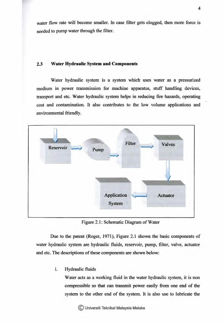
2.3 Water Hydraulie System and Cmnponents
Water hydraulic system is a system which uses water as a pressurized
medium in power transmission for machine apparatus, stuff handling devices,
transport and etc. Water hydraulic system helps in reducing fire hazards, operating
cost and contamination. It also contributes to the low volume applications and
environmental friendly.
R . _.J-.,_
eservorr -1' Pump
Filter ---J
-_,
Application
System
__ ,
Actuator
Figure 2.1: Schematic Diagram ofWater
Due to the patent (Roger, 1-971), Figure 2.-1 shown the basic components of
water hydraulic system are hydraulic fluids, reservoir, pump, filter, valve, actuator
and etc. The descriptions of these components are shown below:
1. Hydraulic fluids
Water acts as a working fluid in the water hydraulic system, it is non
compressible so that can transmit power easily from one end of the
system to the other end of the system. It is also use to lubricate the
© Universiti Teknikal Malaysia Melaka
5
moving parts. in the system to reduce friction loss and help to cool .the
components in the system. Besides, the working fluid should assist in
removing contaminant-s to filter to avoid blockage. It also plays role as
seal against leakage inside a hydraulic component of the system.
n. Reservoir
The function of a reservoir in water hydraulic system is used to store
the system's fluid which is water. Generally, the material of reservoirs
is stainless steel or plastic or metal which coated with metal corrosion
resistant material. The size of reservoir is larger than conventional
hydraulic system.
111. Pump
Pumps used to create flow in water hydraulic system. Fluid is drawn
into the cavity of pump opening during the half cycle and then- expels
the fluid from the cavity of the pump closing for the other cycle.
(Andrew, March 1999) Various types of pump can be used in water
pump system such as piston pump, gear pump, vane pump, axial
piston pump, radial pump and etc.
tv. Filter
This device use to keep clean for the system component from dirt and
minute particles. 'This can help to prevent blocking in the -components
of the system and avoid from wear of those components. Filter can be
installed between the components of the system and also install in the
reservoir. The coarse type of filter install in the reservoir to remove
large particle, while separate filter install between the components of
the system to remove finer elements from entering the system.
v. Valves
There are three types of control valves can be used in water hydraulics
system pump. Generally, the control valves inelude directional control
valve, pressure valve and flow control valves. The function of
directional control valves is ·used to ·control the water flow path by
© Universiti Teknikal Malaysia Melaka
6
.changing the ports of the valve so that flow of fluid can be direct .to
the desire way. Pressure valves are divided into pressure relief valves,
pressure reducing valves and sequence valve. Pressure relief valves
are use to control the overloading of flow in the system. While
pressure ·reducing valves and sequence valves are used to reduce the
supply pressure and using pressure to manage the sequence of
hydraulic circuits.
v1. Actuators
Actuators that used in the hydraulic system are cylinder and hydraulic
motor. Cylinder which is also called as linear actuator is used to
produce straight line motion for the hydraulic system pump. There are
two types of cylinder which are single acting cylinder and double
acting cylinder. The single acting cylinder has only one fluid chamber
and produce force only in one direction. While the double acting
cylinder can operated in two ways and power stroke can be produced
in either way. Hydraulic motor also cal-led as rotary actuators which
can produce rotary motion for the hydraulic pump.
2.4 Types of CODtamiDation
Generally, contamination divided into two types, externally contamination
and internally contamination. External contaminant is generated from outside the
·system while internal contaminant is generated within the system. Both types -of the
contaminants are grouped as particulate contamination which is made of various
materials of solid particles. External contaminant includes dirt, grimes and others.
Internal contaminants exist when some of the components of the system wear. The
contaminants may come from wear pump;, actuator, seal and bearing. (Weibing D. &
Larry S., 2004)
© Universiti Teknikal Malaysia Melaka
7
2.5 Causes of Contamination
According -ttt Majumdar S.R. (2002), contaminants can be generated in a
hydraulic system through:
• Insufficient cleaning of component parts which generated d-uring
manufacturing or assembly).
• The -refilt fluid-may be-polluted before entering the system.
• Wear particles are continually being generate by an operating system.
• Chemical breakdown of the hydrau-lic fl-uid.
• Occurring of cavitations.
-e- Ingest airborne contaminants throu-gh -air breather and -cylinder rod seals.
• Ingestion of contaminants during servicing or installation or replacement of
components in the system.
2.-6 P-roblems Caused- By Contamination
A number of problems which caused by contaminant are stated in Majumdar
S.R. (2002) as shown as below:
• S-peed- up the wear of components in the sys-tem, thu-s influ-ence the s-ystem
performance and service life.
• Slow dttWn the operat-ion of the system and cau-se the moving parts not
operate smoothly.
• Score finely finished s-u-rfaces and- lead- to-leakage by damage seal.
• Causing leakage and losing control during operation when contaminants stop
valves from sealing properly.
• Act as a catalyst in assisting the oxidation of hydraulic and breakdown.
© Universiti Teknikal Malaysia Melaka