Abstract: Even though gold nanorod doped dielectrics have been widelyused for optical laser writing and patterning there has been no attemptto study the dynamic range of these nanocomposites, let alone exploringways to improve this property. Here we study the dynamic range of a goldnanorod doped polyvinyl alcohol film for various laser spot sizes at twodifferent laser pulse repetition rates and show that when a high repetitionrate laser source is employed the dynamic range of the nanocompositeis severely limited due to accumulative heating inside the focal volume.This problem could be solved by silica-coating the nanorods inside thepolymer matrix. This method does not compromise the high repetition rateof the laser writing source and yet retains the attractive flexible propertiesof the polymer matrix. The silica-coated gold nanorod doped polymernanocomposite could be an attractive medium for future high-speed, highrepetition rate pulsed laser writing and patterning applications.
References and links1. M. A. El-Sayed, “Some interesting properties of metals confined in time and nanometer space of different
shapes,” Acc. Chem. Res. 34, 257-264 (2001).2. O. Wilson, G. J. Wilson, and P. Mulvaney, “Laser writing in polarized silver nanorod films,” Adv. Mater. 14,
1000-1004 (2002).3. J. Perez-Juste, B. Rodrıguez-Gonzalez, P. Mulvaney, and L. M. Liz-Marzan, “Optical control and patterning of
gold-nanorod-poly(vinyl alcohol) nanocomposite films,” Adv. Funct. Mater. 15, 1065-1071 (2005).4. J. W. M. Chon, C. Bullen, P. Zijlstra, and M. Gu, “Spectral encoding on gold nanorods doped in a silica sol-gel
matrix and its application to high density optical data storage,” Adv. Funct. Mater. 17, 875-880 (2007).5. J. Perez-Juste, P. Mulvaney, and L. M. Liz-Marzan, “Patterning and encryptation using gold nanoparticles,” Int.
J. Nanotechnol. 4, 15-225 (2007).6. S. Link, C. Burda, M. B. Mohamed, B. Nikoobakht, and M. A. El-Sayed, “Laser photothermal melting and
fragmentation of gold nanorods: Energy and laser pulse-width dependence,” J. Phys. Chem. A 103, 1165-1170(1999).
7. S. S. Chang, C. W. Shih, C. D. Chen, W. C. Lai, and C. R. C. Wang, “The shape transition of gold nanorods,”Langmuir 15, 701-709 (1999).
8. B. Nikoobakht, and M. A. El-Sayed, “Preparation and growth mechanism of gold nanorods (NRs) using seed-mediated growth method,” Chem. Mater. 15, 1957-1962 (2003).
9. S. Link, and M. A. El-Sayed, “Spectroscopic determination of the melting energy of a gold nanorod,” J. Chem.Phys. 114, 2362-2368 (2001).
#84932 - $15.00 USD Received 5 Jul 2007; revised 27 Aug 2007; accepted 27 Aug 2007; published 10 Sep 2007
(C) 2007 OSA 17 September 2007 / Vol. 15, No. 19 / OPTICS EXPRESS 12151
10. H. Petrova, J. Perez-Juste, I. Pastoriza-Santos, G. V. Hartland, L. M. Liz-Marzan, and P. Mulvaney, “On thetemperature stability of gold nanorods: comparison between thermal and ultrafast laser-induced heating,” Phys.Chem. Chem. Phys. 8, 814-821 (2006).
11. F. Cooper, “Heat transfer from a sphere to an infinite medium,” Int. J. Heat Mass Transfer, 991-993 (1977).12. H. Inouye, K. Tanaka, I. Tanahashi, and K. Hirao, “Ultrafast dynamics of nonequilibrium electrons in a gold
nanoparticle system,” Phys. Rev. B 57, 11334-11340 (1998).13. T. Nishino, S. C. Kani, K. Gotoh, and K. Nakamae, “Melt processing of poly(vinyl alcohol) through blending
with sugar pendant polymer,” Polymer 43, 2869-2873 (2002).14. A. Bejan, Heat transfer (John Wiley and Sons, 1993).15. W.J. Roff, and J.R. Scott, Fibres, films, plastics and rubbers, a handbook of common polymers (Butterworths,
London, 1971).16. R. C. Weast, and D. R. Lide, CRC handbook of chemistry and physics, 85th ed. (CRC press: Boca Raton, Florida,
2004), pp. 4-82.17. L. M. Liz-Marzan, M. Giersig, and P. Mulvaney, “Synthesis of nanosized gold-silica core-shell particles,” Lang-
muir 12, 4329-4335 (1996).18. A. L. Stepanov, D. E. Hole, A. A. Bukharaev, P. D. Townsend, and N. I. Nurgazizov, “Reduction of the size of
the implanted silver nanoparticles in float glass during excimer laser annealing,” Appl. Surf. Sci. 136, 298-305(1998).
19. The parameters used in the equation are ρsil=2200 kgm−3, ksil=1.3 Wm−1K−1, cp,sil=750 Jkg−1K−1.20. S. Link, C. Burda, M. B. Mohamed, B. Nikoobakht, and M. A. El-Sayed, “Femtosecond transient-absorption
dynamics of colloidal gold nanorods: Shape independence of the electron-phonon relaxation time,” Phys. Rev. B61, 6086-6090 (2000).
21. M. Hu, X. Wang, G. V. Hartland, V. Salgueirino-Maceira, and L. M. Liz-Marzan, “Heat dissipation in gold-silicacore-shell nanoparticles,” Chem. Phys. Lett. 372, 767-772 (2003).
1. Introduction
Metallic nanorods have received much attention because of their anisotropic surface plasmonresonance featuring a large, polarization dependent absorption cross section which can be tunedthroughout the visible wavelength range [1]. One of the most promising applications that ben-efits from these optical properties of gold nanorods is optical laser writing and patterning[2, 3, 4, 5]. Herein the nanorods are embedded in a dielectric matrix and the anisotropy ofthe embedded particles is exploited by inducing a morphological change from a rod shape intothe energetically favored spherical geometry by pulsed laser excitation [6, 7].
In such applications the laser pulse energy is the primary source of shape control, but otherfactors such as the thermal and mechanical properties of the dielectric matrix also play animportant role. In previous studies soft polymer materials such as polyvinyl alcohol (PVA)[2, 3] and ureasils [5] as well as more rigid materials such as silica sol-gel glasses [4] wereemployed as the matrix material. These nanocomposites have all demonstrated to successfullywithstand the particular pulsed laser irradiation conditions.
However, to accommodate the various laser irradiation conditions such as repetition ratesand pulse energy densities, it is desirable to study the matrix performance at high power, highrepetition rates to ultimately determine the damage threshold conditions. The so-called laserwriting dynamic range of the nanocomposite can then be determined by the range bound byrecording threshold and damage threshold for a specific irradiation condition.
Even though gold nanorod doped dielectrics have been under intense investigation [2, 3, 4,5] there has been no attempt to study the dynamic range of these nanocomposites, let aloneexploring ways to improve this property imperative to patterning applications. While a polymersuch as polyvinyl alcohol (PVA) is an attractive matrix because of its mechanical properties andease in doping, its low Tg and softness compared to other dielectric materials warrants a lowdamage threshold and dynamic range. Furthermore, its low thermal conductivity means that itis prone to heat accumulation upon irradiation with a high repetition rate laser source, whichsignificantly limits the dynamic range. These issues need to be resolved for the reliable use ofthe nanocomposite in optical laser writing and patterning applications.
#84932 - $15.00 USD Received 5 Jul 2007; revised 27 Aug 2007; accepted 27 Aug 2007; published 10 Sep 2007
(C) 2007 OSA 17 September 2007 / Vol. 15, No. 19 / OPTICS EXPRESS 12152
Here we study both experimentally and theoretically the laser writing dynamic range of agold nanorod doped PVA film for various laser spot sizes at two different laser pulse repetitionrates. We show indeed that at a high repetition rate the heat accumulation in the PVA matrixresults in a severely limited dynamic range. We also show that this limited dynamic range canbe improved up to 70% by silica coating of the gold nanorods, without compromising the highpulse repetition rate of the laser source. This could be particularly valuable for future high speedlaser writing and patterning applications.
This paper is organized as follows. In section 2 we describe the apparatus used in the experi-ments, and in section 3 the dynamic range of a PVA matrix doped with uncoated gold nanorodsat various laser spot sizes is presented. We modeled our system using a two-dimensional heatdissipation model doped with point sources of heat, which is described in section 4, followedby section 5 in which the improvement in the dynamic range of the nanocomposite by silicacoating of the nanorods is presented. Finally, concluding remarks are presented in section 6.
2. Experimental
Gold nanorods with an aspect ratio of ∼4.4 were prepared using a silver nitrate assisted, seedmediated growth method, based on the system developed by Nikoobakht et al. [8]. The nanorodswere then homogeneously dispersed in a PVA film by mixing a purified nanorod solution (par-ticle concentration ∼2 nM) with a 10% PVA solution, after which 10 μL of the mixture wasdropcast on a cover slip and dried at 70 ◦C. This resulted in a PVA film of about 50 μm thicknesswith a homogeneous nanorod concentration of ∼25 nM (∼1.5x10 13 nanorods per cm3).
Laser writing of patterns was achieved by femtosecond pulsed laser illumination at 850 nm(Spectra-Physics Tsunami, 100 fs pulse widths, 82 MHz repetition rate). The pulse train wasfocused through a 0.7 NA objective lens. All patterning was conducted 12 μm below the sur-face. The exposure time was controlled by an electronic shutter and was 25 ms per exposurein all experiments (equivalent to 2.05×10⁶ laser shots per exposure). All pulse energies andlaser fluences mentioned in the remainder are the values in the focal plane of the objective.Laser fluences indicated are spatially and temporally averaged over a single laser pulse. Thepatterns were imaged using low power continuous wave illumination at the recording wave-length with a laser scanning microscope operated in transmission (Olympus BX300, 1.2 NAwater immersed objective lens). The recording threshold was determined by the lowest laserpulse fluence for which contrast was observed. The damage threshold was identified using amicroscope equipped with a white light source and a 100x magnification objective, in whichdamage was identified as deformation at the surface of the sample.
Absorption spectra of a written bit pattern were measured using a homebuilt micro spec-trophotometer. Light from a collimated white light source (Oriel Apex Quartz Tungsten Halo-gen source) was focused onto the sample through a 1.2 NA water immersed objective andcollected in transmission using a 0.8 NA infrared enhanced objective lens. The light was redi-rected to a spectrograph (Acton Spectrapro 300i) and dispersed onto a charge coupled device(Princeton Instruments PIXIS 100).
3. Effect of NA and laser pulse repetition rate on recording and damage thresholds
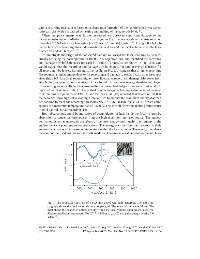
In Fig. 1 we show the extinction spectrum of a PVA film doped with gold nanorods with aTEM micrograph of the gold nanorods on a copper grid. The average dimensions of the embed-ded nanorods are 52 nm x 12 nm leading to an average aspect ratio of 4.4 ± 0.5 (distributionobtained by analyzing >200 particles in TEM micrographs). The inset shows the change inextinction spectrum upon pulsed laser irradiation. Recording was done through a 0.7 NA objec-tive lens using a laser fluence of 7.6 mJcm−2. A clear decrease in extinction is observed aroundthe laser wavelength, whereas the extinction at shorter wavelengths increases. This is consistent
#84932 - $15.00 USD Received 5 Jul 2007; revised 27 Aug 2007; accepted 27 Aug 2007; published 10 Sep 2007
(C) 2007 OSA 17 September 2007 / Vol. 15, No. 19 / OPTICS EXPRESS 12153
with a recording mechanism based on a shape transformation of the nanorods to lower aspectratio particles, which is caused by heating and melting of the nanorods [4, 6, 7].
When the pulse energy was further increased we observed significant damage to thenanocomposite upon irradiation. This is displayed in Fig. 2 where we show patterns recordedthrough a 0.7 NA objective lens using (a) 7.6 mJcm−2 and (b) 9 mJcm−2. Using a 0.7 NA ob-jective lens we observe significant deformation in and around the focal volume when the laserfluence exceeded 8.6 mJcm−2.
To investigate the origin of the observed damage we varied the laser spot size by system-atically reducing the back aperture of the 0.7 NA objective lens, and identified the recordingand damage threshold fluences for each NA value. The results are shown in Fig. 2(c). Onewould expect that the recording and damage thresholds occur at similar energy densities forall recording NA lenses. Surprisingly, the results in Fig. 2(c) suggest that a higher recordingNA requires a higher energy density for recording and damage to occur, i.e., smaller laser spotsizes (high NA focusing) require higher laser fluence to record and damage. Moreover fromsimple thermodynamic considerations [4] we found that the pulse energy densities employedfor recording are not sufficient to cause melting of the embedded gold nanorods. Link et al. [9]reported that it requires ∼65 fJ of absorbed photon energy to heat up a similar sized nanorodto its melting temperature of 1300 K, and Petrova et al. [10] reported that at around 1000 Kthe nanorods show signs of reshaping. However, we found that the maximum energy absorbedper nanorod to reach the recording threshold (NA 0.7, I∼6.5 mJcm −2) is ∼33 fJ, which corre-sponds to a maximum temperature rise of ∼600 K. This is well below the melting temperatureof gold nanrods for all recording NAs.
Both observations could be indicative of accumulation of heat inside the focal volume byabsorption of sequential laser pulses from the high repetition rate laser source. The embed-ded nanorods act as nanoscale absorbers of the laser energy and transfer their energy to theenvironment via phonon-phonon interactions. The energy transfer from the nanorods to theirenvironment causes an increase in temperature within the focal volume. The energy then dissi-pates out of the focal volume into the bulk medium. The time interval between sequential laser
500 600 700 800 900 10000.0
0.2
0.4
0.6
0.8
ext. (arb. u.)
wavelength (nm )
700 800 900-0.2
-0.1
0.0
0.1
Δ ext
wavelength (nm )
Fig. 1. The extinction spectrum of a PVA film doped with gold nanorods. The TEM mi-crograph shows the gold nanorods on a copper grid. The scale bar indicates 50 nm. Theinset shows the change in optical density within the focal volume upon pulsed laser irra-diation (irradiation parameters: NA 0.7, λ = 850 nm, texp=25 ms, pulse energy density 7.6mJcm−2.)
#84932 - $15.00 USD Received 5 Jul 2007; revised 27 Aug 2007; accepted 27 Aug 2007; published 10 Sep 2007
(C) 2007 OSA 17 September 2007 / Vol. 15, No. 19 / OPTICS EXPRESS 12154
0.1 0.2 0.3 0.4 0.5 0.6 0.7
0
1
2
3
4
5
6
7
8
9(a)
(b)
recording threshold dam age threshold
fluence (mJcm
-2)
NA
(c)
Fig. 2. Bit patterns recorded through an 0.7 NA objective lens using pulse energies of (a)7.6 mJcm−2 and (b) 9 mJcm−2. The size of the whole recorded pattern is 30 μm × 30 μm.(c) Recording threshold (open circles) and damage threshold (solid circles) as a functionof NA of the recording lens. The error bars indicate the standard deviation of the spread incontrast obtained from all 16 recorded bits. The error bars for the damage threshold are ofthe order of the symbol size.
pulses is 12.5 ns, which is significantly shorter than the time required for heat to diffuse out ofthe focal volume (simulated to be ∼2 μs for a spherical focal volume in PVA with a radius of 1μm using Cooper’s heat dissipation model [11]). Hence over time, the energy from successivelaser pulses accumulates in and around the focal volume and causes the PVA to heat up.
As mentioned above, the rise in temperature of the gold nanorods caused by the laser pulsesis not enough to reach their melting temperature. However, the temperature of the nanorodsembedded in the nanocomposite is governed by both the temperature of the surrounding matrixand the temperature rise induced by the pulsed laser illumination. If the matrix surrounding thenanorods heats up, the additional absorbed laser energy could elevate the temperature inside thenanorods above their melting point. The maximum temperature of the surrounding matrix forrecording without damage is limited by the decomposition temperature of PVA, which is ∼540K [13]. The combined effect of the locally hot matrix and the pulsed laser irradiation (inducingΔT∼600K, see above) results in a maximum nanorod temperature of∼1140 K, which is in goodagreement with previously reported melting temperatures for similar sized nanorods [9, 10].The fact that the recording and damage thresholds do not occur at a constant energy density fordifferent NAs (Fig. 2 (c)) indicates that the size of the focal volume plays a critical role in theaccumulative heating process. A more quantitative theoretical validation of this observation isdiscussed in the next section.
To verify experimentally that the effects observed using a high repetition rate laser source areindeed caused by cumulative heating we repeated the above experiment using a low repetitionrate laser source (Spectra Physics Spitfire, repetition rate 1 kHz, wavelength 800 nm). Here theinter-pulse separation (1 ms) is significantly longer than the characteristic time for diffusion ofheat out of the focal volume (∼2 μs), thus excluding accumulative heating. The recording anddamage thresholds obtained using the low repetition rate laser are shown in Fig. 3. The highestNA we used was 0.3 because our power meter did not allow measurement of the extremely lowaverage powers required for the higher NA objective lenses. We observe that the recording anddamage threshold occur at similar energy densities for all recording NAs, thus confirming that
#84932 - $15.00 USD Received 5 Jul 2007; revised 27 Aug 2007; accepted 27 Aug 2007; published 10 Sep 2007
(C) 2007 OSA 17 September 2007 / Vol. 15, No. 19 / OPTICS EXPRESS 12155
Fig. 3. Recording threshold (open circles) and damage threshold (solid circles) as a functionof NA of the recording lens, using a low repetition rate laser source. The error bars for therecording threshold are of the order of the symbol size.
the effects observed using a high repetition rate laser source are due to accumulative heating.The slight increase in threshold observed for increasing NA may be due to the size of thedamaged region inside the focal volume being below the detection limit of our imaging system.
4. Theoretical modeling of heat accumulation in the laser focal volume.
To obtain a better insight into the accumulative heating process in a nanoparticle doped dielec-tric we employed a two dimensional heat dissipation model in which the embedded nanorodswere modeled as point absorbers, which is a reasonable assumption on the length scale of sev-eral microns. The nanoparticles absorb photon energy, which is converted to thermal energyand dissipated into the surrounding medium. The nanoparticles thus act as point sources ofthermal energy. These point sources were homogeneously distributed within an infinite (non-absorbing) PVA matrix with an inter-particle distance of ∼400 nm (calculated from the particleconcentration in our experiment). The relevant timescales involved [12] are the electron-phononrelaxation time τe-ph (typically < 5 ps) and the phonon-phonon relaxation time τ ph-ph (typically> 150 ps). Because τe-ph << τph-ph it is reasonable to assume that the absorbed energy is re-leased instantaneously by the point source. The generation and dissipation of thermal energyfrom an instantaneous point source into the PVA gives rise to a time and position dependenttemperature change Θ which can be expressed as [14]
Θ(r,t) = T (r,t)−T0 =Q
8ρcp(παt)3/2exp
[−(r− r0)2
4αt
], (1)
where T0 is the initial temperature (293 K), Q is the amount of thermal energy released by thepoint source, ρ is the density of PVA (1200 kgm−3), cp is the specific heat capacity of PVA[15] (1650 Jkg−1K−1), r− r0 is the radial distance away from the point source, and α is equalto k / ρcp where k is the thermal conductivity of the nanocomposite. The value for the thermalconductivity depends on the volume fraction of nanorods and silica present in the polymernanocomposite. As in our experiment the combined volume fraction of gold and silica is lessthan 0.1% we assumed a value for k equal to that for PVA (0.21 Wm−1K−1 [15]).
To model the experimentally observed homogeneous dispersion of the nanorods, the point
#84932 - $15.00 USD Received 5 Jul 2007; revised 27 Aug 2007; accepted 27 Aug 2007; published 10 Sep 2007
(C) 2007 OSA 17 September 2007 / Vol. 15, No. 19 / OPTICS EXPRESS 12156
sources were distributed on a hexagonal grid. To simulate the random alignment of the nanorodsin the polymer matrix we assigned a randomly generated Q to each individual nanoparticle.This distribution of Q values was spatially multiplied by a Gaussian function to account forthe intensity distribution inside the focal volume. The nanoparticles in the area bounded bytwice the full width at half maximum of the Gaussian intensity distribution were included inthe calculations.
The time dependent temperature distribution after absorption of a single laser pulse by an en-semble of nanoparticles can be obtained by superposing the solutions for n individual particles.The absorption of subsequent laser pulses at a fixed interval can be calculated by incorporatinga temporal offset in Eq. 1.
A typical temperature map of the focal volume obtained from Eq. 1 is shown in Fig. 4(a). Thetemperature distribution in and around the focal volume was evaluated 12.5 ns after absorptionof 200 consecutive laser pulses at a repetition rate of 82 MHz. The random value for Q wasset to a maximum of 50 fJ for a nanorod fully aligned to the laser light polarization. Assuminga typical absorption cross section for nanorods [4] of 5×10⁻¹² cm2 this corresponds to anexperimental laser fluence of 10 mJcm−2. This amount of absorbed energy is insufficient tocompletely melt the gold nanorods [9] and thus closely represents our experimental conditions.The Gaussian intensity distribution is shown at the top, the radius r foc was set to 1 μm in thisparticular case. One can observe a significantly elevated average temperature within r foc due toaccumulative heating.
In our experiments we observed that the laser spot size had a profound effect on the degree ofaccumulative heating (Fig. 2(c)). To verify this observation we varied the theoretical parameterrfoc and simulated the temperature profile within the focal volume while keeping the laser pulsefluence constant. The average temperature, defined as the mean temperature within the focal
-2 -1 0 1 2-2
-1
0
1
2
0 100 200 300 400 500
293
298
303
308
313
Tavg (K)
rfoc = 0.5 μm
rfoc = 1.0 μm
rfoc = 2.0 μm
# pulses
(b)(a)
rfoc
y (μm)
x (μm )
324 K293 K
Fig. 4. (a) Typical calculated temperature distribution in and around the focal volume 12.5ns after absorption of 200 laser pulses at a repetition rate of 82 MHz. The intensity dis-tribution within the focal volume is shown at the top (rfoc = 1 μm). (b) Calculated averagetemperature within the focal volume 12.5 ns after absorption of a number of laser pulsesfor different rfoc. The repetition rate of the laser source was 82 MHz (closed symbols) or1 kHz (open symbols). The results for different rfoc for the low repetition rate laser sourceoverlap. The error bars were obtained by performing fifteen independent calculations forwhich a new distribution of random Q was defined. The error bars indicate the standarddeviation of the spread in Tavg.
#84932 - $15.00 USD Received 5 Jul 2007; revised 27 Aug 2007; accepted 27 Aug 2007; published 10 Sep 2007
(C) 2007 OSA 17 September 2007 / Vol. 15, No. 19 / OPTICS EXPRESS 12157
volume bounded by rfoc is then plotted against the number of laser pulses and the results areshown in 4(b). The simulation clearly indicates that the larger the size of the laser focus (i.e.,rfoc = 2 μm, NA of focusing objective lens is lower), the more heat accumulates and hence thelower the recording and damage thresholds. This is exactly what was observed in Fig. 2(c). Wealso simulated the temperature profiles for a low repetition rate (1 kHz) excitation laser source.The simulation did not show any accumulative heating for any r foc or number of laser shots,which confirms our experimental result in the preceding section.
In the initial stages of heat accumulation (< 100 laser pulses or t < 1 μs) we do not observea significant difference in the rate at which the average temperature increases. This is an effectcaused by the spacing between the embedded gold nanoparticles. Thermal energy dissipatesaway from the gold nanoparticles but due to the low thermal conductivity of PVA the rate atwhich this thermal energy diffuses is limited. The small heat baths surrounding the nanopar-ticles have not merged yet and do not interact. Once the small heat baths merge and form alarge heat bath the size of the focal volume we observe a significant difference in the rate atwhich the thermal energy accumulates. A smaller focal spot size has a larger surface to volumeratio and thus has more surface area available for heat to dissipate to the matrix surrounding thefocal volume. This results in a lower rate of accumulative heating for smaller focal spot sizes.This confirms our experimental observation that the higher NAs require a higher pulse fluenceto obtain resolvable bit contrasts.
5. Effect of silica coating on the dynamic range
As we have shown in Fig. 2 the observed damage to the nanocomposite material limits thedynamic range of the recording medium (defined as the range of fluences required obtaining10% to 90% of the maximum achievable contrast) when a high repetition rate laser is em-ployed. It would therefore be favorable to increase the damage threshold and thus the dynamicrange of the proposed recording medium. As is shown in Fig. 4(a) the areas with the highesttemperature are expected to occur in close proximity to the embedded nanorods. Therefore aneffective method to increase the damage threshold and the dynamic range would be to employa high melting temperature dielectric coating on the nanoparticle surface. Such a method is ad-vantageous for improving thermal properties without compromising the favorable mechanicalproperties of the polymer matrix. For this purpose we choose silica as the coating dielectric forits high melting temperature [16] (∼1700 K) compared to gold nanorods and PVA. The silicacoating is known to withstand the gold nanorod reshaping without deformation, as studied byChon et al. [4].
Silica coating of the nanorods was achieved using a method previously used to coat goldnanospheres as described by Liz-Marzan et al. [17], which we applied to gold nanorods. Thesilica shell thickness used in the study described here was 12 nm. Before dispersion into a PVAfilm the silica coated rods were treated with polyvinylpyrolidine to reduce clustering inside thePVA matrix.
To investigate the effect of a silica coating on the dynamic range of the nanocomposite werecorded patterns using the high repetition rate laser. The laser fluence and the numerical aper-ture were varied as before and the contrasts obtained are shown in Fig. 5(a). Only contrastscorresponding to patterns without damage to the matrix material are shown. As can be seen asilica coating affects both the recording behavior and the damage threshold of the nanocom-posite. The change in recording behavior is caused by the mechanical rigidity of the silicashell, resulting in an increase in pulse energy density required to cause a shape change of thenanorods (i.e. the slope of the curve in Fig. 5(a) is modified). The improved damage thresholdof the polymer nanocomposite is attributed to the favorable thermal properties of the silica shellcompared to PVA. Also the recording threshold increased slightly due to the stabilizing role of
#84932 - $15.00 USD Received 5 Jul 2007; revised 27 Aug 2007; accepted 27 Aug 2007; published 10 Sep 2007
(C) 2007 OSA 17 September 2007 / Vol. 15, No. 19 / OPTICS EXPRESS 12158
Fig. 5. (a) Bit pattern contrasts obtained from transmission images for patterns recordedwith three different numerical apertures in PVA samples doped with uncoated nanorods(open symbols) and silica coated nanorods (solid symbols). The lines are a guide to theeye. The error bars indicate the standard deviation of the spread in contrast obtained fromall 16 recorded bits. (b) Dynamic range as a function of NA for PVA samples doped withuncoated gold nanorods (open circles) and silica coated nanorods (solid circles). The insetshows a TEM micrograph of the silica coated nanorods on a copper grid, the scale barindicates 50 nm.
the rigid silica shell, but this change was small compared to the increase in damage threshold.These effects have resulted in an average increase in dynamic range for a nanocomposite dopedwith silica coated nanorods of almost 70%, as depicted in 5(b). Also the improvement in dy-namic range is larger for higher NAs, which is promising for future development of the laserwriting material where higher NA objective lenses are required to pattern finer details at higherresolution.
The large effect of such a thin silica shell can be better understood by considering the tempo-ral evolution of the temperature distribution around the nanoparticles. As a first order approxi-mation we consider the thermal diffusion length R [18], which gives an estimate of the lengththat heat will diffuse in a time τ ,
#84932 - $15.00 USD Received 5 Jul 2007; revised 27 Aug 2007; accepted 27 Aug 2007; published 10 Sep 2007
(C) 2007 OSA 17 September 2007 / Vol. 15, No. 19 / OPTICS EXPRESS 12159
R =
√kτ
ρcp, (2)
where ρ , cp, and k are the density, specific heat capacity and thermal conductivity of the silicashell [19]. The diffusion length related to the phonon-phonon relaxation time is important, asthis is the timescale on which the majority of the thermal energy is transferred to the surround-ing matrix. Based on observation by Link et al. [20] that the gold nanorods and nanoparticlesdo not differ in electron-phonon and phonon-phonon relaxation times (hence heat transfer) dueto the size regime of rods and particles all being equal or less than the mean free path of theelectron in gold metal (∼50 nm), the phonon-phonon relaxation time is estimated to be ∼80ps according to the value reported by Hu et al. for gold nanoparticles with a thick, 80 nm sil-ica shell [21]. The thermal diffusion length for a gold nanoparticle in silica is then estimatedto be 3.2 nm. This indicates that the highest density of thermal energy is expected in an ex-tremely thin shell surrounding the nanoparticle. Hence the maximum energy density and thusthe maximum peak temperature reached in the PVA matrix material is significantly lower whenthe particles are silica coated, which could explain the significant increase in damage thresholdobserved in the experiment where the nanorods have a silica shell.
6. Conclusions
We studied the dynamic range of a gold nanorod doped polyvinyl alcohol film for various laserspot sizes at two different laser pulse repetition rates and showed that when a high repetition ratelaser source is employed the dynamic range of the nanocomposite is limited due to accumulativeheating inside the focal volume. We also found that the rate at which heat accumulates stronglydepends on the size of the focal volume, which was confirmed by theoretical simulations. Weproposed a solution to this problem by silica coating of the gold nanorods and showed anincrease in dynamic range of 70% when the nanorods were silica coated. The attractivenessof the solution lies in the fact that the nanocomposite can withstand the high repetition rate ofthe laser source and yet retain the favourable mechanical properties of the polymer matrix. Theproposed silica-coated gold nanorod doped polymer nanocomposite is especially attractive forfuture high-speed, high repetition rate pulsed laser writing and patterning applications.
#84932 - $15.00 USD Received 5 Jul 2007; revised 27 Aug 2007; accepted 27 Aug 2007; published 10 Sep 2007
(C) 2007 OSA 17 September 2007 / Vol. 15, No. 19 / OPTICS EXPRESS 12160


![Nanocomposite [5]](https://static.documents.pub/doc/80x56/577c7ecf1a28abe054a26499/nanocomposite-5.jpg)