Abstract – Sinusoidal pulse width modulated pulses are used in
adjustable speed drives for better efficiency. These pulses have
high frequency components that propagate both along the coil and
also in a traverse direction by capacitive coupling. End effect is a
highly non-linear voltage distribution causing stress on inter-turn
insulation. Such a stress tends to lower the insulation integrity in
the motor. The mismatch between cables surge impedance and
motor surge impedance causes a multiple reflection at the line-end
coil and cable junction. Study have been made by computer
simulation and verified by experiments. The patterns of
disturbance in line-end coil voltage waveforms prove the presence
of impending inter-turn faults.
Keywords: SPWM techniques, Adjustable speed drives, High
frequency components, inter-turn faults, line-end voltages
I. INTRODUCTION
Suseptance of inter-turn insulation against repetitive voltage surges has been an area of concern [1]. However, use of thyristors and bipolar transistors did not pose a real threat. Most of the failures were due to inferior materials and incorrect work style. With improvement in technology, Insulated Gate Bipolar Transistors (IGBT) and Metal Oxide Semiconductor Field Effect Transistor (MOSFET) have come into vogue. These switches with very low rise times ≤200ns can produce a switching scenario with a carrier frequency of 30 MHz to 100 MHz. A motor coil that acts more as a low pass filter diverted the surges into the inter-coil and inter-turn capacitances causing a pronounced a non-linear inter-coil and inter-turn voltage distribution; leading to premature motor failures [2][3]. Modern day practice of retrofitting the drives with state of the art switches has only aggravated the problem [4] [5]. Among the major factors attributed for motor failures, bearing failures are put at 22% [5]. Enough literature is available that address the causes and remedies to bearing faults causing broken rotor bars [6] [7].
Present day technology has made it possible for low voltage random wound (basket winding) motors with ratings up to 1500 kW to be used as adjustable speed drives in process industries. Any inter-turn fault, bring incipient in nature, has made it very difficult to identify the fault at a nascent stage [4] [5]. This instability can lead to situations of unexpected breakdown of critical drives.
Standards on rotating machines laid down by IEC, IEEE and NEMA recommend tests that check only the quality of the insulation system against substandard material and workmanship. Motors clearing such tests do not guarantee satisfactory site operation [8]. Compounding the problem is the fact that motors using form-wound coils are mostly addressed by the standards; and form-wound coils have long been manufactured with established production techniques [9].
Cables have been known to mitigate surges acting as a low pass filter. Studies by Melfi, et al. prove that the use of present day low loss cables enable the voltage surges in the sinusoidal envelope to reach the motors; un-attenuated in magnitude and with meager increase in rise times [2]. Stone G.C opines that present guidelines by IEEE-522 on surge testing would be inadequate and revisions in the standard are likely to be elaborated clarifications [6].
II. VOLTAGE DISTRIBUTION DUE TO FAST SURGES
A motor winding acts as a low-loss transmission line for a voltage surge travelling along the winding [10]. Surges transmitted by capacitance coupling use stator core as the return path. Due to difference in surge impedance of a coil in the slot region and the overhang region, there are multiple reflections of the travelling voltage surge along the turns of the coil. Fast rising voltage surges transmitted at carrier frequency take to capacitance coupling between the turns [10].
A. Low-loss transmission line model of an induction motor
The motor winding acts as a transmission line for the voltage applied. With an inherent low resistance, inter-turn to earth capacitive coupling overrides mutual inductive couplings in a winding. The core will act as a magnetic member with very low suseptance [10]. By convention, the windings are mostly delta connected and in some cases, in star with insulated neutral. This gives rise to a situation where-in the voltage pulses can get reflected from the insulated ends of the windings. Constructional aspects of the winding in a stator core can further accentuate the non-linearity in voltage distribution, particularly in stator winding laid out in random wound distribution [3]. Fast rise times of ≤200 ns of modern day switches ensure a very high capacitive coupling.
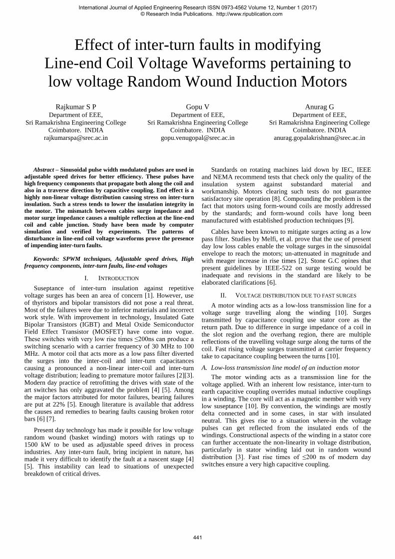
Winding is delta connected. Configuration for simulation is given in Fig. 2.
Fig. 2 Delta Winding
A.3 Calculations of Inter-turn parameters:
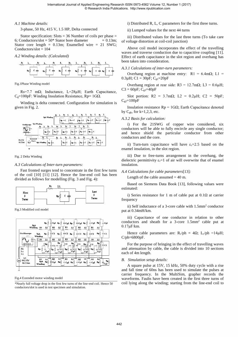
Fast fronted surges tend to concentrate in the first few turns of the coil [10] [11] [12]. Hence the line-end coil has been divided as follows for modelling (Fig. 3 and Fig. 4):
Fig.3 Modified coil model
Fig.4 Extended motor winding model
i) Distributed R, L, C parameters for the first three turns.
ii) Lumped values for the next 44 turns
iii) Distributed values for the last three turns (To take care of voltage distortion at coil-coil junction)
Above coil model incorporates the effect of the travelling waves and traverse conduction due to capacitive coupling [11]. Effect of earth capacitance in the slot region and overhang has been taken into consideration.
A.3.1 Calculations of inter-turn parameters:
Overhang region at machine entry: R1 = 6.4mΩ; L1 = 0.3µH; C1 = 30pF; Cg1=20pF
Overhang region at rear side: R3 = 12.7mΩ; L3 = 0.6µH; C3 = 60pF; Cg3=40pF
Insulation resistance Rp = 1GΩ; Earth Capacitance denoted by Cgk, for k=1,2,3, etc.
A.3.2 Basis for calculation:
i) For the 21SWG of copper wire considered, six conductors will be able to fully encircle any single conductor; and hence shield the particular conductor from other conductors and the core.
ii) Turn-turn capacitance will have r=2.5 based on the enamel insulation, in the slot region.
iii) Due to free-turns arrangement in the overhang, the
dielectric permittivity r=1 of air will overwrite that of enamel insulation.
A.4 Calculations for cable parameters[13]:
Length of the cable assumed = 40 m.
Based on Siemens Data Book [13], following values were estimated:
i) Series resistance for 1 m of cable put at 0.1Ω at carrier frequency
ii) Self inductance of a 3-core cable with 1.5mm2 conductor put at 0.34mH/km.
iii) Capacitance of one conductor in relation to other conductors and sheath for a 3-core 1.5mm2 cable put at 0.17μF/km.
For the purpose of bringing in the effect of travelling waves and attenuation by cable, the cable is divided into 10 sections each of 4m length.
B. Simulation setup details:
A square pulse at 15V, 15 kHz, 50% duty cycle with a rise and fall time of 60ns has been used to simulate the pulses at carrier frequency. In the MultiSim, grapher records the waveforms. Faults have been created in the first three turns of coil lying along the winding; starting from the line-end coil to
*Nearly full voltage drop in the first few turns of the line-end coil. Hence 50 conductors/slot is used in test specimen and simulation.
the end of the winding; the faults are assumed to progress when R-phase changes from a healthy 1GΩ to a low 1kΩ. The oscillograms obtained were exported to spreadsheet environment for further study.
C. Test specification and Experimental setup:
Due to the proven fact that inter-turn voltage remains unaffected by the rotor, only the stator of an induction motor was used as a specimen. The stator used is that of 1.5HP, 3-phase, and 36 slot motor. The winding configuration uses 3 coils/pole/phase in a 4-pole arrangement. Each coil has 50 turns. The windings are of mush-wound or basket type. Tappings are attached to the first three turns of the line-end coil and coil junctions are also accessible through tappings. The stator specimen is shown in Fig. 5.
Fig.5 Test specimen
Fig. 6 Test setup
Fig. 7 Test voltage
A square pulse generated with 15Vp at 15 kHz has been used. A 40m long PVC insulated wire connected the pulse generator to the stator coil. The rise time of the pulse is 60ns. The DSO used is a 60MHz dual channel with tuned 1:1 probes. The test set-up is shown in Fig.6. The waveform at motor-cable junction is shown in Fig.7.
Resistors representing inter-turn insulation values (10MΩ, 1MΩ, 100kΩ, 10 kΩ and 1kΩ) were used across tappings to simulate the effect of variation is insulation resistance. The oscillograms obtained were exported to the spreadsheet environment for further study.
III. COMPARISON OF SIMULATION AND EXPERIMENTAL
RESULTS
A. R-phase winding (first two turns of line-end coil tested with
discrete resistors):
Cable end voltage waveforms for fault at junction of first and second Turns at R-phase start (Figs. 8, 9 and 10):
Fig. 8 R-phase cable-motor junction waveform
Fig.9 Modification in the rear end of the waveform
B. B-phase winding (first two turns at B-phase start, tested with
discrete resistors):
Cable end voltage waveforms for fault at junction of 1st and 2nd turns at B-phase start:
Fig.11 Simulation Results
Fig.12 Experimental Results
IV. JUSTIFICATIONS OF EVALUATION METHODOLOGY
A value of 5MΩ is considered satisfactory for motors with random-wound coils and rated below 1kV [14].
The interpretation is that an insulation value more than 1MΩ is generally considered healthy and a value one order less shows degradation.
To get better clarity of line-end voltage waveforms, the mismatch between surge impedance of cable and motor (Zcable=51Ω and Zwinding=108Ω) has been reduced by terminating the cable with its surge impedance. However such practice is rarely resorted to, in practice.
Most of higher power ASD motors use IGBT as switching devices. These switches are used around 10 and 20 kHz and rise time are of the order of 50ns. The output from the practical pulse generator resembles the above condition as close as possible.
V. INFERENCES
A. Test on R-phase
Oscillograms in Fig.8 (time instance between 0 and 17μs) show the effect of inter-turn fault at the beginning of R-phase. While the difference in the pattern of the waveforms between
10MΩ and 10kΩ is negligible, there is a marked difference between waveforms pertaining to 10kΩ and 1kΩ. Considering oscillogram in Fig.9 (36 to 50μs), a small discernable difference has started showing for waveform patterns between 10MΩ and 10kΩ. This difference becomes more pronounced in the subsequent cycles due to the effect of reflected waves from other phases.
The pattern in oscillograms pertaining to Fig. 8 and Fig.9 is confirmed by the experimental result shown in Fig.10. While the difference in the initial waveform pattern is marked for low values (typically a few kΩ) of insulation resistance for oscilloscope samples between 1000 and 3000, such a difference has started emerging only towards the latter half of the waveform for higher values of insulation resistance (typically a few MΩ) as seen between DSO samples 3000 to 4000.
A comparison of Fig.8, Fig. 9 and Fig. 10 shows that while the insulation resistance values are healthy (typically above 1MΩ), the line-end coil voltage waveform pattern is nearly the same. Subsequently, when the degradation in insulation strength starts showing (typically between 1MΩ and a few kΩ), the patterns start showing a difference after a few cycles. When the insulation degradation has progressed to a non-recovery level (typically lower than a few kΩ), the difference in waveform pattern shows up right in the beginning of waveforms due to the high damping of high frequency capacitive current by the low value of insulation resistance; markedly elongating the waveform oscillations towards the end of the cycle.
B. Test on B-phase
Considering the inter-turn fault at the beginning of B-phase, waveforms for this condition is shown in Fig. 9 and Fig. 10.
With reference to the oscillograms shown in Fig.9, all waveforms pertaining to insulation resistance values of 10MΩ, 10kΩ and 1kΩ have started showing different patterns in the first cycle of carrier waveform; though the difference between waveforms pertaining to 10kΩ and 1kΩ is more marked. Such behaviour is corroborated by experimental results shown in Fig.12.
The behaviour seen in Fig.11 and Fig. 12 are due to reflected waves from the beginning of B-phase (in about 460ns) to the line-end coil in R-phase (about 168m of winding length and the stator core essentially acting like an air core for high frequencies). These reflected waves void of high frequency content, modify the line-end voltage waveform.
C. Comparison with site conditions
The carrier waveforms pulses form the sinusoidal envelope. One phase will show up a negative value while the other two phases will be positive. Further, long cables used will create more pronounced oscillations due to travelling waves. Both these conditions will produce a more distorted and magnified voltage pattern in comparison with the simulation.
Inter-turn insulation ages more due to partial discharges. This discharge carbonises the void in the insulation ultimately lowering its resistance. Hence the modifications in insulation value using discrete resistors can be justified.
D. Failure Process in Random Wound Insulation System
Adjustable Speed Drives employing voltage source converters of the pulse width modulation type have become common in motors with voltage rating of ≤690V and with advances in IGBT technology, are now being applied to medium voltage motors with form wound insulation system. One of the major issues concern the effect of steep high frequency voltage surges created in such drives. Such voltage surges lead to additional voltage and thermal stress on the stator winding insulation system; leading to a premature failure of stator winding insulation [15] [16].
Fig.13: Cross-section of a random wound stator insulation system
A typical random wound insulation system used in motors with a voltage rating of ≤690V is shown in Fig. 13. Normally such motors have type I insulation system. Such a system is not expected to experience partial discharges (PD) in normal service conditions. The drives are expected to age by thermo-mechanical stresses rather than electrical [16].
In any random winding, the turns are placed in a random manner and possibility of tiny air gaps existing between turns and slot liners is a reality [16]. Under the influence of PWM surges with rise times of less than 100ns, the line-end coil voltages can be as much as 3 to 4 times the rated phase-to-ground voltages. Any excessive voltage either due to steep rise times or cable mismatch will cause partial discharges to show up at carrier frequency [17]. Repetitive discharges will eventually erode the magnet wire insulation and cause premature failure of stator winding insulation. Once the turn insulation fails, a large current flowing will eventually melt the copper and ground-wall insulation [17]. Such a failure will always resemble a thermal failure though the cause would have been inter-turn failure. Further the voltage waveform from a PWM converter can lead to increased ground-wall insulation heating and accelerate the normal thermal ageing process [17]. This dielectric loss is generally modelled as an ideal (lossless) capacitor in parallel with a resistor [14] [18]. While this dielectric loss is very minimal at power frequency, it can cause excessive heating in the dielectric and age the insulation faster at carrier frequency [17].
Except IEC, North American Standards have been silent regarding requirements of adjustable speed drives. IEC standard, namely IEC 60034-15-41 tries to address the problem by laying down that no partial discharge should occur below a stipulated surge voltage level. For example, a 460V motor intended for use in a severe surge environment should have a partial discharge inception voltage higher than 2800V [17].
This stipulation would enormously increase the cost of the motor used in the adjustable speed drive. However, there is still not enough clarity with respect to the insulation type II being used in form wound insulation system and all the relevant standards are still in a draft form.
VI. CONCLUSIONS
1. Variable frequency drives can produce pulses that penetrate a motor winding both in longitudinal and traverse modes.
2. Inter-turn faults can progress into major earth faults.
3. Surge impedance mismatch between cable and motor accentuates the line-end voltages at the junction.
4. A combined distributed and lumped parameter model of a winding facilitates a better study of voltage distribution.
5. The line-end voltages between simulation and testing agree in essential details.
6. Predictions based on the line-end coil disturbances can point to the likelyhood of inter-turn fault.
7. There is marked differnce between line-end voltages under healthy and unsafe insultation levels.
8. Diagnosis using line-end voltage disturbances can be used as non-intrusive technique for condition monitoring of random wound motors.
Acknowledgement
Authors thank the management for having funded and
enabled the work to this stage of completion.
References [1] J.M.Weed, “Prevention of transient voltages in windings”, Trans. AIEE,
Vol. 41, pp. 149–159, 1922.
[2] M. Melfi et.al., “Effect of Surge Voltage Rise Time on the Insulation of Low Voltage Machines Fed by PWM Converters”, IEEE Indl. Applications Meeting, Vol.1, pp.239-246, 1997.
[3] S.Bell et.al.,. “Will Your Motor Insulation Survive a New Adjustable-Frequency Drive?”, IEEE Trans. Indl. Applications, Vol.33, No.5, pp.1307-1311, 1997.
[4] T.F.Lowery et.al., “Application Considerations for PWM Inverter-Fed Low Voltage Induction Motors”, IEEE Trans. Indl.Applications, Vol.30, No.2, pp.286-293, 1994.
[5] O.V.Thorsen et.al., “A survey of faults on induction motors in offshore oil industry, petrochemical industry, gas terminal and oil refineries”, IEEE Trans. Ind. Applications, Vol. 31, No. 5, pp. 1274-1279, 1995.
[6] G.C.Stone, “Recent Important Changes in IEEE Motor and Generator Winding Insulation Diagnostic Testing Standards”, IEEE Trans.Indl.Applications, Vol.41, No.1, pp. 91-100, 2005.
[7] R.R. Schoen et. al., “An unsupervised on-line system for induction motor fault detection using stator current monitoring”, IEEE Trans.Indl.Applications, Vol.36, No.6, pp.1280-1286, 1995.
[8] O.Ondel et.al., “A method to detect broken bars in induction machine using pattern recognition techniques”, IEEE Trans.Indl.Applications, Vol.42, No.4, pp. 916-923, 2006.
[9] “Guide for Testing Turn-to-Turn Insulation on Form Wound Stator Coils for Alternating Current Rotating Electrical Machines”, IEEE Std. 522-2004.
[10] B.S.Oyegoke, “A Comparative Analysis of Methods for calculating the Transient Voltage distribution within the Stator Winding of an Electric Machine subjected to Steep-Fronted Surges”, Proceedings of the 8th International Conference on Electric Machines and Drives, 1-3 September, Cambridge, U.K. IEE Publication No. 444, pp.294-298, 1997.
[12] W. T. Weeks, “Multi-conductor transmission line theory in the TEM approximation”, IBM Journal of Research and Development, Vol. 16, No. 6, pp. 604-611, 1972.
[14] “IEEE Recommended Practice for Testing Insulation Resistance of Rotating Machinery”, Table 3, IEEE Std. 43-2000.
[15] IEC 60034-18-41, “Evaluation and Qualification of Electrical Insulation Systems Used in Rotating Electrical Machines When Fed from Voltage Converters”.
[16] Meredith K.W. Stranges, et.al. “Exploring the IEC 60034-18-41 and IEC 60034-18-42 Technical Specifications for Inverter Duty Motor Insulation”, IEEE Industry Applications Magazine, Jan/Feb 2007, pp. 37-42.
[17] Stone G.C., et. al., “Stator insulation problems associated with low voltage and medium voltage PWM drives”, Cement Industry Technical Conference, April-May 2007, pp. 187-192.
[18] R. Bartnikas, “Engineering Dielectrics Volume IIB – Electrical Properties of Solid Insulation Materials”, ASTM STP 926, 1987.