Internal curing can reduce alkali-silica reaction (ASR) damage in concrete. Alkali reactions with chert in natural sand caused damaging ASR in plain concrete. However, ASR damage was minimal in companion internally cured (IC) concrete in which a portion of the sand was replaced with pre-wetted lightweight aggregate (LWA). IC improved paste quality through a quantita-tive reduction in paste porosity and unhydrated cement. This was assessed using quantitative paste characterization including image analysis of backscattered electron (BSE) images, quantitative fluo-rescent intensity assessment, resistivity measurements, and qual-itative analyses using SEM-EDS and polarized light microscopy. In concretes with the same water-cement ratio (w/c), IC concrete has denser paste microstructure from increased hydration due to additional water from pre-wetted LWA. Less permeable paste reduced fluid ingress, ASR reaction, and crack propagation. This demonstrates the potential of internal curing as a mitigation tool in reducing damage from ASR when high cement content and poten-tially reactive aggregates are used.
INTRODUCTIONInternal curing refers to the use of pre-wetted lightweight
aggregate (LWA) or other water-filled inclusions including pre-wetted crushed returned concrete fines, superabsorbent polymers, and pre-wetted wood fibers that can provide curing water throughout the concrete.1 A portion of the conventional fine aggregate fraction used in the mixture is replaced by a pre-wetted LWA.
Originally, internal curing gained most attention due to its ability to counteract the effects of self-desiccation and mitigating autogenous and drying shrinkage cracking.2,3 Further, the use of pre-wetted LWA has been associated with several additional benefits—for example, showing to reduce the likelihood for plastic shrinkage cracking4 as well as thermal cracking.5 Finally, more recently, it has been seen that internal curing is able to reduce water absorption as well as fluid and chloride transport6,7 as a consequence of a well-hydrated and denser microstructure. Schlitter et al.5 demonstrated that water from a LWA can move out and cure the cement paste up to 2 mm (0.079 in.) around the LWA.
While the importance of internal curing using pre-wetted lightweight aggregate (LWA) in reducing early-age cracking due to internal desiccation and in increasing cement hydra-tion8,9 is well recognized, the role of LWA in reducing alkali- silica reaction (ASR) damage in a concrete is not well understood. The effect of internal curing on ASR expansion in mortar was studied by Shin et al.,10 who conducted an accelerated mortar bar test (ASTM C1260) on five mortar
mixtures including plain mortar and four other mortar mixtures with variable amounts of replacements of reactive sand with LWA and with nonreactive sand. Results of these tests showed that all the samples exhibited expansion after 10 days. However, there were differences in the timing of when rapid expansion occurred and differences in the expan-sion rate among the specimens. These researchers showed that the rate of expansion of plain mortar began to increase rapidly at 10 days and kept increasing throughout the testing period. On the other hand, expansion of mortar mixtures with replacement of a portion of the reactive sand with either LWA or nonreactive sand occurred at later times; and the expansion rate was lower than the plain mortar.
ASR is known as a deleterious chemical reaction between alkali hydroxides from the concrete pore solution and silica of reactive aggregate resulting formation of ASR gel in concrete. It is known that the beginning of the expansion takes place within the aggregate containing the reactive silica.11 Damage can be caused as the ASR gel in reactive aggregate absorbs moisture and causes extreme pressure from expansion, which can cause cracking of aggregate and paste, sometimes resulting in longer-term durability prob-lems, reduced serviceability, increased maintenance costs, reduced service life, and susceptibility to additional deteri-oration mechanisms. ASR as a threat to concrete structure durability was first recognized 70 years ago.11 Since then, research has been performed in an effort to understand ASR mechanism and developing appropriate assessment, repair, and prevention methods.
It is well known that concrete produced with high-alkali cement, high cement content, and potentially reactive aggre-gates is susceptible to damage and expansion due to ASR.11,12 Several ways of controlling ASR include use of nonreactive aggregates, use of low-alkali cement (0.60% Na2O equiva-lent maximum), limiting alkali content in concrete, use of supplementary cementitious materials (SCMs), and/or use of lithium salts as admixtures.12 Until now, a better approach to reduce the permeability of concrete is by using SCMs, such as fly ash or ground slag in the mixture.12 SCMs can reduce ASR expansion by binding with alkalis and limiting alkali availability for reaction with reactive siliceous aggre-gates.11 The pozzolanic reaction or slag hydration produce denser paste by reducing the amount of calcium hydroxide and producing additional calcium silicate hydrate (C-S-H)
Title No. 114-M37
Effect of Internal Curing as Mitigation to Minimize Alkali-Silica Reaction Damageby Mengesha A. Beyene, Jose F. Munoz, Richard C. Meininger, and Carmelo Di Bella
ACI Materials Journal, V. 114, No. 3, May-June 2017.MS No. M-2016-058.R2, doi: 10.14359/51689562, was received August 25, 2016,
gel. This effect reduces the mobility of ions and possibly slows the reaction rate, making the concrete less permeable to external moisture and alkalis as well.
In this study, the potential of internal curing from the use of pre-wetted LWA in reducing ASR damage was investi-gated. The study was conducted by comparing internally cured concrete with companion plain concrete (control sample) cured in similar conditions and for the same time. The two concretes are the same except that a portion of the sand was replaced by pre-wetted LWA in the internally cured concrete. The goal of this study is to investigate and eval-uate if internal curing can mitigate damage from ASR in a concrete when high-alkali cement, high cement content, and potentially reactive aggregates are used.
The hypothesis was internal curing from the use of pre-wetted LWA may have increased the degree of cement hydration, resulting in a more dense and less permeable paste microstructure that reduces the mobility of ions and possibly slows the reaction rate and makes it difficult for microcracks to grow and propagate from the site of ASR gel inception (potentially reactive aggregate) into the surrounding areas. If true, with some partial replacement of fraction of the fine aggregate, it may be able to mitigate the reaction and damage with high cement content and potentially reactive aggregates in concrete. The second goal of this research is to investigate whether voids in the LWA have contributed in mitigating ASR damage by providing relief through ASR gel migrating into the LWA void structure, thus reducing swelling pressure.
RESEARCH SIGNIFICANCEThe significance of this research is to investigate the effect
of internal curing as a mitigation tool in minimizing ASR damage when concrete made with high alkali cement, high cement content, and potentially reactive aggregates are used. If the result of this study proves that internal curing using pre-wetted LWA is effective in minimizing ASR damage in concrete, with partial replacement of fine aggregate, it may be possible to mitigate ASR and associated damage when high cement content and potentially reactive aggregates are used. This research will provide a better understanding of the benefit of internal curing in reducing ASR damage in portland cement concrete.
MATERIALSProportions, curing, and age of concrete
The concrete mixtures were produced using a relatively well-graded 0.75 mm (3/4 in.) maximum size crushed lime-stone and dolomitic limestone. The cement used in the mixture was Type I cement with alkali expressed as Na2O = 0.86% from an Indiana cement plant. Two mixtures, one
plain and the second one containing pre-wetted aggregate, were produced. The mixture proportions are presented in Table 1. The type of LWA used in this research project was expanded shale manufactured in Brooklyn, IN. The amount of LWA needed in the concrete mixture (the amount of water for internal curing), is established according to Bentz and Snyder13 and Bentz et al.,14 which is based on the chem-ical shrinkage of the cement, the degree of saturation of the aggregates, and the adsorption of the aggregates.
A portion (560 kg/m3 [35.0 lb/ft3]) of the conventional fine aggregate (No. 16, No. 8, and No. 4 sieve sizes) was replaced by 338 kg/m3 (21.1 lb/ft3) LWA coarse sand. The specific gravity of the LWA used to make the mixture design was 1.56 according to manufacturer data. The LWA sand used in the internally cured concrete was oven-dried and soaked in water for 24 ± 1 hour with water levels kept above the top of the aggregates. The water absorption of the LWA increased from 6% at the sixth hour to 10.4% at the end of 24 ± 1 hour. The absorption of the LWA is determined according to the test procedure of developed by the Department of Transpor-tation of the State of New York.15 After 24 hours, the excess water was decanted and used as part of the mixing water. To avoid loss of water to evaporation, the LWA was covered with plastic sheets before mixing. Water was added to the cement and aggregate mixture in the mixer and the concrete was mixed for 3 minutes, followed by a 3-minute rest and a 2-minute final mixing. After mixing, the two concrete mixtures were used to prepare cylinders 4 in. (102 mm) in diameter and 8 in. (203 mm) in length, in accordance with ASTM C192-12.16
The day after casting, the samples were demolded, sealed in plastic bags, and stored in a climatic chamber at 22.8°C (73°F) and approximately 50% RH. The samples were cured in the bags for approximately 1 year. Afterwards, the samples were saturated in water tanks until the day of testing for coefficient of thermal expansion (CTE).
METHODSPetrographic methods
The petrographic analyses of plain and LWA mixtures were performed using visual observation, an optical stereo-microscope, polarized light microscope (PLM), fluorescence microscopy, and scanning electron microscope (SEM) with energy dispersive spectroscopy (EDS).
Reflected light and transmitted light microscopy—Each type of concrete cylinder (for example, Fig. 1(a) and (b)) was visually examined and photographed. Two concrete cylinders from each mixture were examined visually and using stereomicroscope. Subsequently, two 19.0 mm (3/4 in.) thick concrete sections were cut longitudinally from each concrete cylinder, and one of the resulting surfaces of
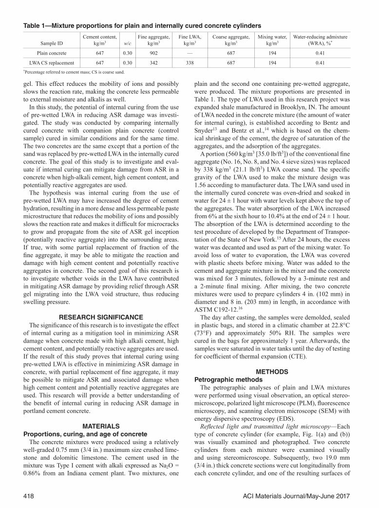
Table 1—Mixture proportions for plain and internally cured concrete cylinders
Sample IDCement content,
kg/m3 w/cFine aggregate,
kg/m3Fine LWA,
kg/m3Coarse aggregate,
kg/m3Mixing water,
kg/m3Water-reducing admixture
(WRA), %*
Plain concrete 647 0.30 902 — 687 194 0.41
LWA CS replacement 647 0.30 342 338 687 194 0.41*Percentage referred to cement mass; CS is coarse sand.
419ACI Materials Journal/May-June 2017
each was lapped (polished) and examined using a stereo- microscope at magnifications up to 90×. Surfaces of freshly fractured concrete were also studied with a stereomicro-scope. Three small representative rectangular blocks were cut from areas of interest of each cylinder, placed on indi-vidual glass microscope slides with epoxy, and reduced to a thickness of approximately 20 micrometers (0.0008 in.). These thin sections were studied using a petrographic PLM at magnifications up to 400× to evaluate relative degree of hydration of cement particles, identify aggregate types, and identify secondary deposits that filled many cracks, including microcracks extending from aggregate particles into the paste. Point count analysis was also performed on thin sections made from plain concrete cylinders using the petrographic optical microscope to estimate the relative proportions of reactive aggregate particles in the concrete.
Fluorescence microscopy—Optical fluorescence micros-copy is based on optical analysis of thin sections made from vacuum-impregnated concrete using a yellow fluo-rescent epoxy. The purpose of impregnation is to fill the capillary porosity, cracks, voids, and any other defects in the concrete samples. Similar to thin sections prepared for transmitted light optical analysis, thin sections were reduced to a thickness of approximately 20 micrometers (0.0008 in.). The resulting thin sections were analyzed using an optical microscope by a combination of a blue excitation filter and a
yellow blocking filter. The LWA concrete and plain concrete have the same water-cement ratios (w/c). Any difference in the shades of green (fluorescence intensity) of the cement paste between two concretes attributes to the differences in degree of hydration. The differences in fluorescence inten-sity in the paste microstructure is a function of the capillary porosity of the cement paste and were used to differentiate relatively porous concrete paste microstructure from a dense concrete paste microstructure.17
Quantitative assessment of fluorescence intensity (porosity) of cement paste using image analysis
Image analysis of high-magnification fluorescent thin section images was performed using image analysis software to determine area fractions occupied by dark green paste, bright/light green paste, and aggregates. The threshold for each area fraction was determined based on previous work published by Jakobsen et al.17 After establishing the thresh-olds for dark green paste, bright green paste, and aggregates (dark), the total percentage of areas occupied by aggregates, dark green paste, and bright green paste were determined using the software. As the area occupied by the paste may not be the same from one area to another within the same sample or between the control concrete and LWA concrete, percentage of dark green paste area to percentage of bright green paste area ratios are used to compare paste quality between the samples (denser and less permeable paste from less dense and relatively permeable paste).
Porosity measurements from backscattered electron images
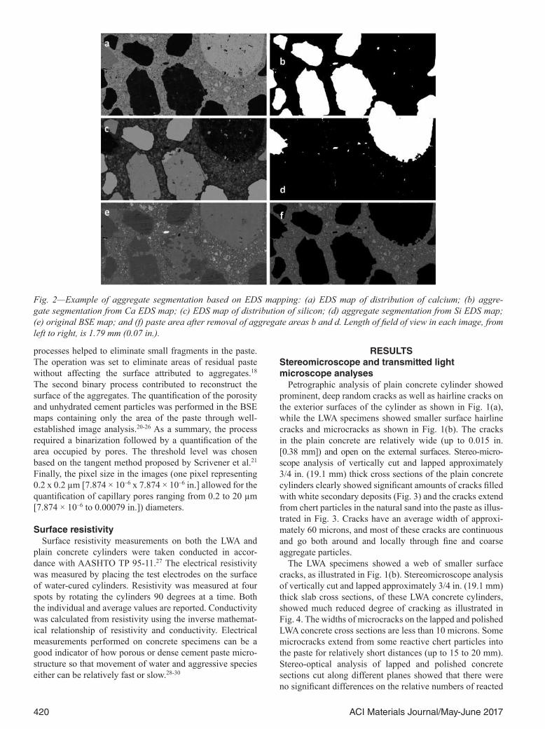
The polished specimens were examined using the same SEM equipped with a concentric backscatter detector coupled with energy dispersive X-ray spectroscopy (EDS/EDX). The microscope was operated under high vacuum at 15 kV and 10 mm (0.4 in.) working distance. Large EDS/EDX mapping areas were collected using EDS microanalysis software. The maps had a total of 299 fields, each one with a 3000× magni-fication, which covered a total area of 1.79 mm2 (0.0028 in.2). Three maps per sample were collected in random areas to ensure that the analysis was representative of each sample. The area in the original backscattered electron (BSE) images attributed to aggregates was removed using an image treat-ment process based on previous work published by Yang and Buenfeld19 (Fig. 2). The aggregate segmentation was based on EDS elemental mapping, principally silicon and aluminum (Fig. 2(a) and (c)) instead of the difference in the gray level.18 The combination of areas low in calcium or silica in the corresponding EDS maps were used to map the entire surface of the aggregates (Fig. 2(b) and (d)). Both aggregate surfaces were then subtracted from the original EDS image to obtain the final paste area, used for porosity measurements as shown in Figure 2(f).
The image analysis software was used for aggregate segmentation of each EDS map. The segmentation was performed through a sequence of four different processes: median filter to reduce the noise,19 conversion into binary images by applying appropriate threshold19 followed by two binary operations, erode, and fill in holes. The first binary
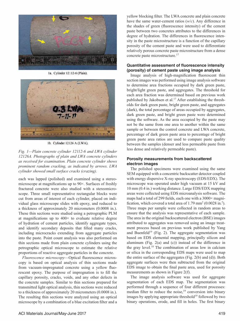
Fig. 1—Plain concrete cylinder 12112-6 and LWA cylinder 12126A. Photographs of plain and LWA concrete cylinders as received for examination. Plain concrete cylinder shows prominent random cracking, as indicated by arrows. LWA cylinder showed small surface cracks (crazing).
420 ACI Materials Journal/May-June 2017
processes helped to eliminate small fragments in the paste. The operation was set to eliminate areas of residual paste without affecting the surface attributed to aggregates.18 The second binary process contributed to reconstruct the surface of the aggregates. The quantification of the porosity and unhydrated cement particles was performed in the BSE maps containing only the area of the paste through well- established image analysis.20-26 As a summary, the process required a binarization followed by a quantification of the area occupied by pores. The threshold level was chosen based on the tangent method proposed by Scrivener et al.21 Finally, the pixel size in the images (one pixel representing 0.2 x 0.2 µm [7.874 × 10–6 x 7.874 × 10–6 in.] allowed for the quantification of capillary pores ranging from 0.2 to 20 µm [7.874 × 10⁻⁶ to 0.00079 in.]) diameters.
Surface resistivitySurface resistivity measurements on both the LWA and
plain concrete cylinders were taken conducted in accor-dance with AASHTO TP 95-11.27 The electrical resistivity was measured by placing the test electrodes on the surface of water-cured cylinders. Resistivity was measured at four spots by rotating the cylinders 90 degrees at a time. Both the individual and average values are reported. Conductivity was calculated from resistivity using the inverse mathemat-ical relationship of resistivity and conductivity. Electrical measurements performed on concrete specimens can be a good indicator of how porous or dense cement paste micro-structure so that movement of water and aggressive species either can be relatively fast or slow.28-30
RESULTSStereomicroscope and transmitted light microscope analyses
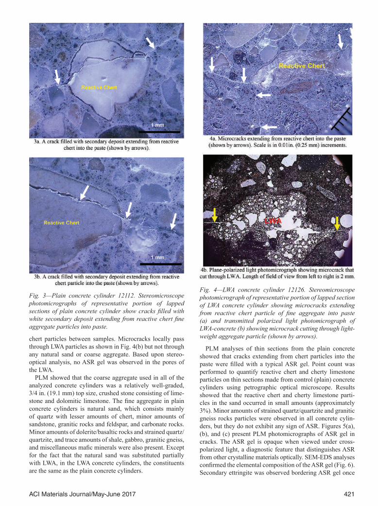
Petrographic analysis of plain concrete cylinder showed prominent, deep random cracks as well as hairline cracks on the exterior surfaces of the cylinder as shown in Fig. 1(a), while the LWA specimens showed smaller surface hairline cracks and microcracks as shown in Fig. 1(b). The cracks in the plain concrete are relatively wide (up to 0.015 in. [0.38 mm]) and open on the external surfaces. Stereo-micro-scope analysis of vertically cut and lapped approximately 3/4 in. (19.1 mm) thick cross sections of the plain concrete cylinders clearly showed significant amounts of cracks filled with white secondary deposits (Fig. 3) and the cracks extend from chert particles in the natural sand into the paste as illus-trated in Fig. 3. Cracks have an average width of approxi-mately 60 microns, and most of these cracks are continuous and go both around and locally through fine and coarse aggregate particles.
The LWA specimens showed a web of smaller surface cracks, as illustrated in Fig. 1(b). Stereomicroscope analysis of vertically cut and lapped approximately 3/4 in. (19.1 mm) thick slab cross sections, of these LWA concrete cylinders, showed much reduced degree of cracking as illustrated in Fig. 4. The widths of microcracks on the lapped and polished LWA concrete cross sections are less than 10 microns. Some microcracks extend from some reactive chert particles into the paste for relatively short distances (up to 15 to 20 mm). Stereo-optical analysis of lapped and polished concrete sections cut along different planes showed that there were no significant differences on the relative numbers of reacted
Fig. 2—Example of aggregate segmentation based on EDS mapping: (a) EDS map of distribution of calcium; (b) aggre-gate segmentation from Ca EDS map; (c) EDS map of distribution of silicon; (d) aggregate segmentation from Si EDS map; (e) original BSE map; and (f) paste area after removal of aggregate areas b and d. Length of field of view in each image, from left to right, is 1.79 mm (0.07 in.).
421ACI Materials Journal/May-June 2017
chert particles between samples. Microcracks locally pass through LWA particles as shown in Fig. 4(b) but not through any natural sand or coarse aggregate. Based upon stereo- optical analysis, no ASR gel was observed in the pores of the LWA.
PLM showed that the coarse aggregate used in all of the analyzed concrete cylinders was a relatively well-graded, 3/4 in. (19.1 mm) top size, crushed stone consisting of lime-stone and dolomitic limestone. The fine aggregate in plain concrete cylinders is natural sand, which consists mainly of quartz with lesser amounts of chert, minor amounts of sandstone, granitic rocks and feldspar, and carbonate rocks. Minor amounts of dolerite/basaltic rocks and strained quartz/quartzite, and trace amounts of shale, gabbro, granitic gneiss, and miscellaneous mafic minerals were also present. Except for the fact that the natural sand was substituted partially with LWA, in the LWA concrete cylinders, the constituents are the same as the plain concrete cylinders.
PLM analyses of thin sections from the plain concrete showed that cracks extending from chert particles into the paste were filled with a typical ASR gel. Point count was performed to quantify reactive chert and cherty limestone particles on thin sections made from control (plain) concrete cylinders using petrographic optical microscope. Results showed that the reactive chert and cherty limestone parti-cles in the sand occurred in small amounts (approximately 3%). Minor amounts of strained quartz/quartzite and granitic gneiss rocks particles were observed in all concrete cylin-ders, but they do not exhibit any sign of ASR. Figures 5(a), (b), and (c) present PLM photomicrographs of ASR gel in cracks. The ASR gel is opaque when viewed under cross- polarized light, a diagnostic feature that distinguishes ASR from other crystalline materials optically. SEM-EDS analyses confirmed the elemental composition of the ASR gel (Fig. 6). Secondary ettringite was observed bordering ASR gel once
Fig. 3—Plain concrete cylinder 12112. Stereomicroscope photomicrographs of representative portion of lapped sections of plain concrete cylinder show cracks filled with white secondary deposit extending from reactive chert fine aggregate particles into paste.
Fig. 4—LWA concrete cylinder 12126. Stereomicroscope photomicrograph of representative portion of lapped section of LWA concrete cylinder showing microcracks extending from reactive chert particle of fine aggregate into paste (a) and transmitted polarized light photomicrograph of LWA-concrete (b) showing microcrack cutting through light-weight aggregate particle (shown by arrows).
422 ACI Materials Journal/May-June 2017
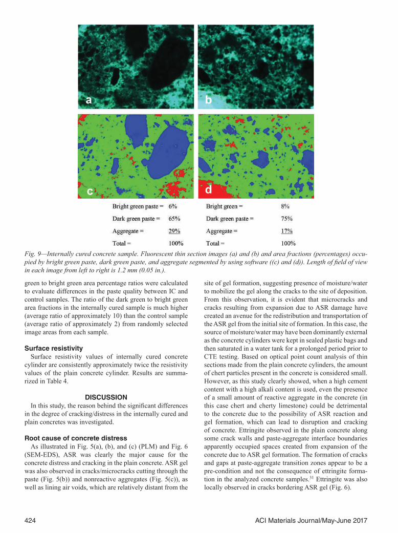
the crack extends from the chert particle into the paste (Fig. 6). SEM-EDS analysis confirmed the morphology as well as the elemental composition of the ettringite (Fig. 6). Figure 6 also shows the chert particles as high in silica (Si), the gel high in calcium (Ca) and silica (Si), and the ettringite as high in sulfur (S) and calcium (Ca). Some cracks/microc-
racks and gaps at paste-aggregate interfaces were also filled with secondary ettringite.
Optical analysis of thin sections confirmed that LWA concrete cylinders did also exhibit some localized and short microcracks that extend from some reactive chert particles into the paste (Fig. 7). Minor ASR gel was observed in a few cracks that extend from some reactive chert particles
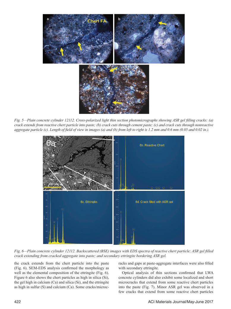
Fig. 5—Plain concrete cylinder 12112. Cross-polarized light thin section photomicrographs showing ASR gel filling cracks: (a) crack extends from reactive chert particle into paste; (b) crack cuts through cement paste; (c) and crack cuts through nonreactive aggregate particle (c). Length of field of view in images (a) and (b) from left to right is 1.2 mm and 0.6 mm (0.05 and 0.02 in.).
Fig. 6—Plain concrete cylinder 12112. Backscattered (BSE) images with EDS spectra of reactive chert particle; ASR gel filled crack extending from cracked aggregate into paste; and secondary ettringite bordering ASR gel.
423ACI Materials Journal/May-June 2017
into the surrounding paste (Fig. 7). Some of the microcracks extending from reactive chert particles cut through LWA particles. No ASR gel was observed in voids of the LWA particles in the analyzed samples. Minor ettringite lining some microcracks was also observed in the LWA concrete.
Quantitative assessment of paste porosity from large area BSE images
The measured capillary porosity (measured using image analysis) is summarized in Table 2. The control specimen
had a higher percentage of “coarse” capillary porosity and unhydrated cement particles when compared with the sample containing lightweight aggregates. The percentage of area attributed to the coarse capillary porosity in the plain concrete samples was 3.4% versus 1.8% calculated in the internally cured LWA concrete sample. In addition to the overall coarse capillary porosity, the size distribution of the measured porosity was compared in Fig. 8 for both samples. The graph indicates that the internally cured sample had not only less but also more refined coarse capillary porosity than the control. The former was found to have more finer pores in the 0.2 to 2 µm (7.874 × 10⁻⁶ to 0.00079 in.) range and less pores above 2 µm when compared to the control spec-imen. Due to the limitation of the method, pore sizes less than 0.2 μm was not included in the analysis. The amount of unhydrated cement in the control sample is approximately 2% higher than the control sample.
Quantitative assessment of fluorescence intensity differences of cement paste using image analysis
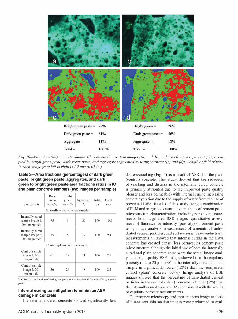
Fluorescence microscopic analysis was performed on thin sections prepared from internally cured and plain concretes to evaluate differences in the cement paste capillary porosi-ties between the two concretes. In a typical portland cement concrete, concrete with low w/c appears dark green due to less fluorescence intensity, as there is a low amount of epoxy present within the paste, whereas sample with high w/c appears bright green due to high fluorescence intensity. Image analysis showed that the dark green paste area fraction in the internally cured concrete is much higher than the dark green area fraction in the plain concrete (Fig. 9 and Fig. 10; Table 3). While Fig. 9(a) and (b) and Fig. 10 (a) and (b) show fluorescent thin section images of internally cured and control (plain) concrete samples, the companion figures (c) and (d) illustrates area fractions of dark green paste, bright green paste, and aggregates segmented using the image processing software. Table 3 summarizes area fractions for internally cured and control sample separately. As the area occupied by the aggregate varies from area to area within the same sample as well as between the two samples, dark
Fig. 7—LWA concrete cylinder 12126. Transmitted light thin section photomicrograph showing crack filled with ASR gel (shown by arrows) extending from reactive chert fine aggre-gate particle into surrounding paste. Length of field of view from left to right is 0.6 mm (0.02 in.).
Table 2—Capillary porosity, between 0.2 and 20 µm size, and unhydrated cement particles determined by image analysis of paste (SD is standard deviation)
Specimen Porosity, % SD Unhydrated cement, % SD
Control 3.4 0.3 7.9 1.2
IC 1.8 0.4 6.1 0.5
Fig. 8—Pore size distribution in paste determined by image analysis; comparison of IC sample with control.
424 ACI Materials Journal/May-June 2017
green to bright green area percentage ratios were calculated to evaluate differences in the paste quality between IC and control samples. The ratio of the dark green to bright green area fractions in the internally cured sample is much higher (average ratio of approximately 10) than the control sample (average ratio of approximately 2) from randomly selected image areas from each sample.
Surface resistivitySurface resistivity values of internally cured concrete
cylinder are consistently approximately twice the resistivity values of the plain concrete cylinder. Results are summa-rized in Table 4.
DISCUSSIONIn this study, the reason behind the significant differences
in the degree of cracking/distress in the internally cured and plain concretes was investigated.
Root cause of concrete distressAs illustrated in Fig. 5(a), (b), and (c) (PLM) and Fig. 6
(SEM-EDS), ASR was clearly the major cause for the concrete distress and cracking in the plain concrete. ASR gel was also observed in cracks/microcracks cutting through the paste (Fig. 5(b)) and nonreactive aggregates (Fig. 5(c)), as well as lining air voids, which are relatively distant from the
site of gel formation, suggesting presence of moisture/water to mobilize the gel along the cracks to the site of deposition. From this observation, it is evident that microcracks and cracks resulting from expansion due to ASR damage have created an avenue for the redistribution and transportation of the ASR gel from the initial site of formation. In this case, the source of moisture/water may have been dominantly external as the concrete cylinders were kept in sealed plastic bags and then saturated in a water tank for a prolonged period prior to CTE testing. Based on optical point count analysis of thin sections made from the plain concrete cylinders, the amount of chert particles present in the concrete is considered small. However, as this study clearly showed, when a high cement content with a high alkali content is used, even the presence of a small amount of reactive aggregate in the concrete (in this case chert and cherty limestone) could be detrimental to the concrete due to the possibility of ASR reaction and gel formation, which can lead to disruption and cracking of concrete. Ettringite observed in the plain concrete along some crack walls and paste-aggregate interface boundaries apparently occupied spaces created from expansion of the concrete due to ASR gel formation. The formation of cracks and gaps at paste-aggregate transition zones appear to be a pre-condition and not the consequence of ettringite forma-tion in the analyzed concrete samples.31 Ettringite was also locally observed in cracks bordering ASR gel (Fig. 6).
Fig. 9—Internally cured concrete sample. Fluorescent thin section images (a) and (b) and area fractions (percentages) occu-pied by bright green paste, dark green paste, and aggregate segmented by using software ((c) and (d)). Length of field of view in each image from left to right is 1.2 mm (0.05 in.).
425ACI Materials Journal/May-June 2017
Internal curing as mitigation to minimize ASR damage in concrete
The internally cured concrete showed significantly less
distress/cracking (Fig. 4) as a result of ASR than the plain (control) concrete. This study showed that the reduction of cracking and distress in the internally cured concrete is primarily attributed due to the improved paste quality (denser and less permeable) with internal curing increasing cement hydration due to the supply of water from the use of prewetted LWA. Results of this study using a combination of PLM and integrated quantitative methods of cement paste microstructure characterization, including porosity measure-ments from large area BSE images, quantitative assess-ment of fluorescence intensity (porosity) of cement paste using image analysis, measurement of amounts of unhy-drated cement particles, and surface resistivity/conductivity measurements all showed that internal curing in the LWA concrete has created dense (less permeable) cement paste microstructure although the initial w/c of both the internally cured and plain concrete cores were the same. Image anal-ysis of high-quality BSE images showed that the capillary porosity (0.2 to 20 µm size) in the internally cured concrete sample is significantly lower (1.8%) than the companion control (plain) concrete (3.4%). Image analysis of BSE images showed that the percentage of unhydrated cement particles in the control (plain) concrete is higher (8%) than the internally cured concrete (6%) consistent with the results of capillary porosity measurements.
Fluorescence microscopy and area fractions image analysis of fluorescent thin section images were performed to eval-
Fig. 10—Plain (control) concrete sample. Fluorescent thin section images ((a) and (b)) and area fractions (percentages) occu-pied by bright green paste, dark green paste, and aggregate segmented by using software ((c) and (d)). Length of field of view in each image from left to right is 1.2 mm (0.05 in.).
Table 3—Area fractions (percentages) of dark green paste, bright green paste, aggregates, and dark green to bright green paste area fractions ratios in IC and plain concrete samples (two images per sample)
Sample IDs
Dark green
area, %
Bright green
area, %Aggregate,
%Total,
%DG/BG*
ratio
Internally cured concrete sample
Internally cured sample image 1, 20× magnitude
65 6 29 100 10.8
Internally cured sample image 2, 20× magnitude
75 8 17 100 9.4
Control (plain) concrete sample
Control sample image 1, 20×
magnitude61 29 11 100 2.1
Control sample image 2, 20×
magnitude56 26 18 100 2.2
*DG/BG is area fraction of dark green paste to area fraction of fraction of bright green paste.
426 ACI Materials Journal/May-June 2017
uate the degree of cement paste porosity (fluorescence inten-sity) and their overall interconnectedness (permeability). In fluorescent light mode, the fluorescence intensity (shades of green) of the cement paste depends on the capillary porosity and the overall interconnectedness of the pores in the paste.17 Area fractions image analysis of fluorescent thin section images showed that the ratio of the dark green to bright green areas in the internally cured sample is much higher (average ratio of 10) than the control (plain) concrete sample (average ratio of 2), indicating that the internally cured concrete has a denser and less permeable microstructure than the plain concrete. Due to the increased hydration, the cement paste in the LWA concrete is darker green in fluorescence light mode than the plain concrete (Fig. 9 and 10), although the initial w/c of the concretes was the same.
It is known that concrete resistivity is affected by change in the paste microstructure.18 The measured surface resis-tivity values of the internally cured concrete cylinder were consistently approximately twice that of the plain concrete cylinder (Table 4), indicating a less permeable cement paste microstructure due to the increased hydration. The result is consistent with literature.32,33
It is evident from direct quantitative assessment of the cement paste and surface resistivity measurements that the cement paste microstructure in the internally cured concrete was apparently significantly denser (reduced capillary porosity and ITZ) due to increased cement hydration due to the additional water supply from the prewetted LWA. As a result, the rate of ASR reaction should have been reduced as the movement of alkali solutions from the paste to reaction sites (chert particles) became difficult due to reduced capil-lary porosity and reduced interconnectivity of the capillary pores (less permeable). Such dense cement paste microstruc-ture might have also made crack growth and propagation more difficult from some of the sites where ASR has already initiated. This interpretation is supported by the fact that in the internally cured concrete, no prevalent cracks were observed and most of the observed microcracks only extend for short distances from reacted chert particles into the adja-cent cement paste (Fig. 7). This resistance to crack propaga-tion in the LWA concrete was interpreted as higher confine-ment capacity of the paste. Increases in paste confinement had been correlated with lower ASR gel formation.34 There-fore, it is logical to expect that lower permeability in the LWA concrete, produced by lower and more refined porosity (as confirmed by SEM) not only contributed to the reduction of alkali mobility but also produced a higher confinement capacity of the paste. Both mechanisms contributed to miti-
gating the ASR damage in the LWA concrete when compared against the plain concrete specimens. Given the fact that the same cement amount was used in the two concretes, the observed relatively low abundance of unhydrated and/or partially hydrated portland cement particles in the inter-nally cured concrete than in the plain concrete concede with the results of quantitative paste characterization and further showed an increased hydration in the LWA concrete. This is obviously due to the additional water supplied from the pre-wetted LWA. The importance of hydration in controlling concrete properties such as strength, permeability, and dura-bility was reviewed in a joint publication by the National Institute of Standards and Technology (NIST) and Federal Highway Administration (FHWA).35
The study of Shin et al.10 on the effect of internal curing on ASR expansion in mortar suggested three possible bene-ficial elements that potentially reduce damage from ASR in the mortars as a result of the LWA10: 1) increase cement hydration and reduced interfacial transition zones (ITZ); the rate of fluid ingress and movement is reduced, which may in turn reduces the rate of ASR reaction; 2) the dilution effect provided by the replacement of LWA for a portion of the reactive particles in the fine aggregate reduces the poten-tial for a portion of the ASR expansion; and 3) extra pores provided by LWA may provide available deposit sites for the gel in such way to minimize the pressure due to expansion.
Although the Shin et al.10 study (on mortars) suggested three possible benefits of replacing a fraction of potentially reactive aggregate with LWA in reducing ASR damage, two out of the three beneficial factors mentioned seem to be less influential based on the present study of 2.5-year-old concrete samples using integrated techniques. Analysis of concrete sections cut along different planes of the LWA concrete cylinders showed that the relative amount of reacted chert particles and associated ASR damage were minimal and not significantly different along the different planes. In the LWA concrete, the microcracks initiated within the reactive particles due to ASR extending into the surrounding paste for a very short distance (maximum 15 to 20 mm [0.59 to 0.79 in.]) as observed from stereo-optical and PLM analyses. On the other hand, the companion plain concrete samples exhibited prevalent ASR gel-filled cracks and microcracks extending from reacted chert particles into the paste. Most of these cracks are relatively continuous and go both around and locally through fine and coarse aggre-gate particles. This shows that the lower amount of reac-tive aggregate in the LWA did not play a significant role for the lesser observed ASR damage in the LWA concrete; the
Table 4—Surface resistivity measurements of plain concrete and LWA concrete cylinders
2nd 27.3 27.2 29.8 28.2*Date received from Purdue University after prolonged soaking.†Resistivity corrected for curing condition.26
427ACI Materials Journal/May-June 2017
reduced permeability due to internal curing did. The pres-ence of as many unreacted chert particles in the internally cured concrete as the plain concrete on concrete sections cut along different planes is also additional confirmation that the dilution effect does not appear to have played a significant role in the observed reduced damage in the internally cured concrete. Agreement of several test results performed using different techniques (including PLM, fluorescence micros-copy, porosity measurements from large area BSE images, and resistivity measurements) confirmed that the reduced permeability of the paste due to improved hydration of inter-nally cured cement paste should have reduced ion diffusion to reactive particles and also apparently have made crack propagation and growth from the reacted chert particles into the paste difficult as observed from stereo-optical and PLM analyses.
In this evaluation of the concrete, no ASR gel was observed in the pore spaces of the LWA particles in the 2.5-year-old concrete, and thus it is unlikely that the pores in the LWA contributed to the reduced ASR damage. Instead, we observed that some microcracks extending from reac-tive chert particles cutting through some LWA particles (Fig. 4(b)) without gel evident in the LWA.
The present study showed that the reduction of cracking and distress in the internally cured concrete is attributed to the overall decrease in capillary porosity, decreased capil-lary pore sizes (Fig. 8), as well decreasing connectivity of the pores, as additional hydration products formed due to consumption of additional water, supplied from prewetted LWA, fills the capillary pore spaces. As a result, the rate of ASR reaction was reduced as the movement of alkali solu-tions from the paste to reaction sites (chert particles) became difficult due to reduced capillary porosity and reduced inter-connectivity of the capillary pores.
CONCLUSIONS AND RECOMMENDATIONSBased on the results of integrated methods of analyses,
including quantitative assessment of the cement paste capil-lary porosity and volume fraction of unhydrated cement particles from large area BSE images; quantitative assess-ment of fluorescence intensity (porosity) of cement paste using image analysis of fluorescent thin section images; surface resistivity measurements; and qualitative analyses including macroscopic visual observation, stereomicro-scope, and optical microscopy (PLM) and SEM-EDS, the following conclusions are drawn:
1. The cause of distress and cracking in two concrete cylin-ders produced with high cement content with relatively high alkali content was ASR. The reactive aggregates are some chert particles in the natural sand fine aggregate. Ettringite crystallized in microcracks and gaps around aggregate parti-cles are a consequence, but not the cause, of these cracks and gaps that resulted from expansion of the concrete due to ASR gel formation and expansion in the concrete.
2. The degree of ASR cracking and damage in the inter-nally cured concrete cylinders with partial replacement of the natural sand with prewetted LWA coarse sand is minimal, and much more localized than the plain concrete
cylinders. The reduction in cracking and distress in the LWA-bearing concrete cylinders is attributed to formation of dense and less permeable paste microstructure due to increased hydration from the use of prewetted LWA. Strong evidence showing higher confinement capacity of the paste in the LWA concrete specimens than in the control were a denser microstructure proved by SEM analysis and a much smaller crack propagation confirmed by extensive petro-graphic analysis. The dense and less permeable paste micro-structure and reduced ITZ should have reduced the rate of fluid ingress and movement, which in turn reduced the rate of ASR reaction and crack propagation.
3. No ASR gel was observed in the pore spaces of LWA particles in 2.5-year-old concrete; thus, it is unlikely that the pores in the LWA contributed to the reduced ASR damage in the LWA concrete.
4. This study clearly showed that the potential of using prewetted LWA in reducing/mitigating ASR damage in a concrete.
DISCLOSURE STATEMENTThe authors do not have any conflicts of interest that could
inappropriately influence this work. The conclusions are the professional opinion of the authors, and do not represent any official policy of FHWA.
ROLE OF THE FUNDING SOURCEThis research was performed using the resources of Turner
Fairbank Highway Research Center, Federal Highway Administration, McLean, VA; no funding was provided from outside sources.
AUTHOR BIOSACI member Mengesha A. Beyene is a Petrographic Expert in SES and Associated LLC at Turner Fairbank Highway Research Center (TFHRC), McLean, VA. His research interests include alkali-aggregate reaction (AAR) and concrete materials.
ACI member Jose F. Munoz is a Researcher in SES and Associated LLC at Turner Fairbank Highway Research Center (TFHRC). He is a member of ACI Committee 241, Nanotechnology of Concrete. His research interests include the effects of nano additives to engineer the structure of cementi-tious materials.
Richard C. Meininger, FACI, is a Research Civil Engineer with the Federal Highway Administration (FHWA) Turner Fairbank Highway Research Center (TFHRC). He received his BSCE and MS degrees from the Univer-sity of Maryland, College Park, MD. He received the ACI Construction Award in 1984 and previously served on the Technical Activities Committee and Board of Direction. His research interests include concrete materials in highways and transportation structures.
ACI member Carmelo Di Bella is a PhD Candidate at ETH Zurich, Zurich, Switzerland. He received his BS in materials science from Milano-Bicocca University, Milan, Italy, and his MS in civil engineering from Purdue University, West Lafayette, IN. His research interests include the chemical and physical characterization of cement-based materials as well as the investigation of macroscopic properties in terms of durability and fracture mechanics.
ACKNOWLEDGMENTSThe authors would like to thank R. H. Jorge for his help in sample prepa-
rations. Many thanks to H. Kim for his assistance in measuring the resis-tivity of the concrete cylinders and T. Vuke for his assistance in areas frac-tion image analysis of fluorescent thin section images.
428 ACI Materials Journal/May-June 2017
REFERENCES1. Bentz, P., and Weiss, J., “Internal Curing: A 2010 State-of-the-Art
and Weiss, J., “Shrinkage Mitigation Strategies in Cementitious Systems: A Closer Look at Differences in Sealed and Unsealed Behavior,” Transporta-tion Research Board, V. 2070, 2007, pp. 59-67.
3. Henkensiefken, R.; Bentz, D.; Nantung, T.; and Weiss, J., “Volume Change and Cracking in Internally Cured Mixtures Made with Saturated Lightweight Aggregate under Sealed and Unsealed Conditions,” Cement and Concrete Composites, V. 31, No. 7, 2009, pp. 427-437.
4. Henkensiefken, R.; Briatka, P.; Dale, B.; Nantung, T.; and Weiss, J., “Plastic Shrinkage Cracking in Internally Cured Mixtures Made with Pre-wetted Lightweight Aggregate,” Concrete International, V. 32, No. 2, Feb. 2010, pp. 49-54.
5. Schlitter, J. L.; Senter, A. H.; Bentz, D. P.; Nantung, T.; and Weiss, J., “A Dual Ring Test for Evaluating Residual Stress Development Due to Restrained Volume Change,” Journal of ASTM International, V. 7, No. 9, 2010.
6. Castro, J.; Spragg, R.; and Weiss, J., “Water Absorption and Electrical Conductivity for Internally Cured Mortars with a W/C between 0.30 and 0.45,” Journal of Materials in Civil Engineering, ASCE, V. 1, No. 1, 2010, pp. 321-321. doi: 10.1061/(ASCE)MT.1943-5533.0000377
7. Di Bella, C.; Villani, C.; Hausheer, E.; and Weiss, J., “Chloride Trans-port Measurements for a Plain and Internally Cured Concrete Mixture,” The Economics, Performance and Sustainability of Internally Cured Concrete, SP-290, A. K. Schindler, J. G. Grygar, and W. J. Weiss, eds., American Concrete Institute, Farmington Hills, MI, 2012, pp. 1-16.
8. Bentz, P. D.; Davis, J. M.; Pelz, M. A.; and Snyder, K. A., “Influence of Internal Curing and Viscosity Modifiers on Resistance to Sulfate Attack,” Materials and Structures, Apr. 2013, doi: 101617/s11527-013-0081-x.
9. Laura, P.; Couch, J.; Jensen, O. M.; and Weiss, J., “Early-Age Acoustic Emission Measurements in Hydrating Cement Paste: Evidence for Cavita-tion during Solidification Due to Self-Desiccation,” Cement and Concrete Research, V. 39, No. 10, 2009, pp. 861-867.
10. Shin, K. J.; Castro, J.; Schlitter, J.; Golias, M.; Pour-Ghaz, M.; Henkensiefken, R.; Peled, A.; and Weiss, J., “The Role of Internal Curing as a Method to Improve the Durability,” S. Kim and K. Ann, eds., Handbook of Concrete Durability, Middleton Publishing Inc., Seoul, Korea, 2010, pp. 379-428.
11. ACI Committee 221, “Report on Alkali-Aggregate Reactivity (ACI 221.1R-98) (Reapproved 2008),” American Concrete Institute, Farmington Hills, MI, 1998, 31 pp.
12. Thomas, M. D. A., “The Effect of Supplementary Cementing Materials on Alkali-Silica Reaction: A Review,” Cement and Concrete Research, V. 41, 2011, pp. 1224-1231.
13. Bentz, D. P., and Snyder, K. A., “Protected Paste Volume in Concrete—Extension to Internal Curing Using Saturated Lightweight Fine Aggregate,” Cement and Concrete Research, V. 29, 1999, pp. 1863-1867.
14. Bentz, D. P.; Laura, P.; and Roberts, J. W., “Mixture Proportioning Internal Curing,” Concrete International, V. 27, No. 2, 2005, pp. 35-40.
15. New York State Department of Transportation Materials Bureau, “Moisture Content of Lightweight Fine Aggregate,” Test Method No.: NY 703-19 E, Code: 7.42-5, 2008, Albany, NY.
16. ASTM C192/C192M-12, “Standard Practice for Making and Curing Concrete Test Specimens in the Laboratory,” ASTM International, West Conshohocken, PA, 2012, 8 pp.
17. Jakobsen., U. H.; Laugesen, P.; and Thaulow, N., “Determination of Water-Cement Ratio in Hardened Concrete by Optical Fluorescence Microscopy, Water-Cement Ratio and Other Durability Parameters—Tech-niques for Determination,” Water-Cement Ratio and Other Durability Parameters, SP-191, M. S. Khan, ed., American Concrete Institute, Farm-ington Hills, MI, 2000, 117 pp.
18. Snyder, K. A.; Feng, X.; Keen, B. D.; and Mason, T. O., “Estimating the Electrical Conductivity of Cement Paste Pore Solutions from OH-, K+, and Na+ Concentrations,” Cement and Concrete Research, V. 33, 2003, pp. 793-798.
19. Yang, R., and Buenfeld, N. R., “Binary Segmentation of Aggregate in SEM Image Analysis of Concrete,” Cement and Concrete Research, V. 31, No. 3, pp. 437-441.
20. Werner, A. M., and Lange, D. A., “Quantitative Image Analysis of Masonry Mortar Microstructure,” Journal of Computing in Civil Engi-neering, V. 13, No. 2, 1999, pp. 110-115.
21. Scrivener, K. L.; Patel, H. H.; Pratt, P. L.; and Parrott, L. J., “Analysis of Phases in Cement Paste Using Backscattered Electron Images,” Micro-structural Development During Hydration of Cement, L. J. Struble and P. W. Brown, eds., Materials Research Society Symposium Proceedings, V. 85, 1987, pp. 67-76.
22. Zhao, H., and Darwin, D., “Quantitative Backscattered Electron Analysis of Cement Paste,” Cement and Concrete Research, V. 22, No. 4, 1992, pp. 695-706.
23. Kjellsen, K. O.; Detwiler, R. J.; and Gjørv, O. E., “Backscattered Electron Image Analysis of Cement Paste Specimens: Specimen Prepara-tion and Analytical Methods,” Cement and Concrete Research, V. 21, No. 2, 1991, pp. 388-390.
24. Lange, D. A.; Jennings, H. M.; and Shah, S. P., “Image Anal-ysis Techniques for Characterization of Pore Structure of Cement-Based Materials,” Cement and Concrete Research, V. 24, No. 5, 1994, pp. 841-853.
25. Diamond, S., and Leeman, M. E., “Pore Size Distributions in Hard-ened Cement Paste by SEM Image Analysis,” Proceedings of the Materials Research Society, V. 370, 1995, pp. 217-226.
26. Igarashi, S. I.; Watanabe, A.; and Kawamura, M., “Evaluation of Capillary Pore Size Characteristics in High-Strength Concrete at Early Ages,” Cement and Concrete Research, V. 35, No. 3, 2005, pp. 513-519.
27. AASHTO TP 95-11, “Standard Method of Test for Surface Resis-tivity Indication of Concrete’s Ability to Resist Chloride Ion Penetration,” American Association of State Highway and Transportation Officials, Washington, DC, 9 pp.
28. Whittington, H. W.; McCarter, W. J.; and Forde, M. C., “The Conduc-tion of Electricity through Concrete,” Magazine of Concrete Research, V. 33, No. 114, 1981, pp. 48-60.
29. Rajabipour, F., and Weiss, W. J., “Electrical Conductivity of Drying Cement Paste,” Materials and Structures, V. 40, No. 10, 2007, pp. 1143-1160.
30. “Test Method for Surface Resistivity Indication of Concrete Ability to Resist Chloride Ion Penetration,” DOTD designation: TR 233-11, Loui-siana Department of Transportation and Development, Baton Rouge, LA, 2011, 6 pp.
31. Fu, Y., and Xie, P., “Gu, P.; and Beaudoin, J. J., “Significance of Pre-existing Cracks on Nucleation of Secondary Ettringite in Steam-Cured Cement Paste,” Cement and Concrete Research, V. 24, 1994, pp. 1015-1024.
32. Young, J. F., and Hansen, W., Microstructural Development during Hydration of Cement, L. J. Struble and P. W. Brown, Materials Research Society, Pittsburgh, PA, 1987.
33. Halamickova, P.; Detwiler, R. J.; Bentz, D. P.; and Garboczi, E. J., “Water Permeability and Chloride Ion Diffusion in Portland Cement Mortars: Relationship to Sand Content and Critical Pore Diameter,” Cement and Concrete Research, V. 25, 1995, pp. 790-802.
34. Ostertag, C. P.; Yi, C.; and Monteiro, P. J., “Effect of Confinement on Properties and Characteristics of Alkali-Silica Reaction Gel,” ACI Materials Journal, V. 104, No. 3, May-June 2007, pp. 276-282.
35. Biernacki, J. J.; Bullard, J. W.; Constantiner, C.; Meininger, R.; Juenger, M.; Cheung, J. H.; Hansen, W.; Hooton, R. D.; Luttge, A.; and Thomas, J. J., “Paving the Way for a More Sustainable Concrete Infrastruc-ture—A Vision for Developing Comprehensive Description of Cement Hydration Kinetics,” National Institute of Standards and Technology, Gaith-ersburg, MD, 35 pp. doi: 10.6028/NIST.SP.1138,2013


![001 1562R383R FRANÇAIS MODE D'EMPLOI [Unit Dose] I ... · 3. Light-cure BOND with a dental curing unit (see table “Dental curing unit and curing time”). Table: Dental curing](https://static.documents.pub/doc/80x56/5f7ba0f1a367dc37781f72b2/001-1562r383r-franais-mode-demploi-unit-dose-i-3-light-cure-bond-with.jpg)


