Page 1
EFFECT OF PHYSICAL AND MECHANICAL PROPERTIES OF PU
BIOPOLYMER MEMBRANES UPON USE OF DIFFERENT FABRICATION
TECHNIQUES
RAHIMAH BINTI ABD RAHIM
A thesis is submitted in partial
fulfillment of the requirement for the award of the
Degree of Master of Mechanical Engineering
Faculty of Mechanical and Manufacturing Engineering
University Tun Hussein Onn Malaysia
SEPTEMBER 2013
Page 2
v
Abstract
In developing polymer membranes that response to prevents liquid water from
penetrating through, while at the same time permitting moisture past out through,
polymer membrane with various structure ranging from dense to highly asymmetric
morphologies (0.01 - 0.25 mm) were fabricated through three different techniques;
blends, curing and grafting fabrication. From FT-IR analysis, BP/PEG (blends, curing
and grafting) were fully converted into solid polymer membrane with functional group of
N-H stretching in region 3350 - 3250 cm-1.
Morphological result of BP/PEG shows three
types of surface; open, close and blind surface with cylindrical blind and ink bottle
shaped structure randomly. Due to lower porosity of skin over a symmetric support acts
as a barrier, BP/PEG polymer membranes resultant no water permeability as compared to
BP/DMF, which exhibit extremely higher water permeability with value 0.161 L/s.m3 at
lower concentration. Water absorption analysis shows that mechanical properties of the
prepared membranes were significantly influenced by their structure and amount of water
absorbed. Thus, BP/PEG (blends, curing and grafting) preparation gave lower amount of
water absorption with less than 0.01% water absorption increment rather than BP/DMF
12% (w/v) with highly porosity value of 0.07%. Thermogravimetric analysis (TGA)
reviewed that the hard segment decomposition temperature was occur at 295 0C – 395
0C,
meanwhile for soft segment at 370 0C – 500
0C. Based upon modulus, tensile, strain and
tear strength also energy at break, evidently shows that the BP/PEG (grafting) method
gave the best performance on physical and mechanical properties with highest mean
value of 12419 N/mm, 14.11 MPa, 38.289 %, 50.67 N/mm and 21.627 N respectively.
Reciprocally, PEG solvent does significantly increase the mechanical properties with the
reaction of BP rather than DMF solvent with varieties of concentration. Moreover,
BP/PEG membrane from each fabrication technique had obvious dense porous structural
feature with open, close and blind pores in practically boundless development as of
adequate final use in membrane application.
Page 3
vi
Abstrak
Dalam membangunkan polimer membran yang menghalang tindak balas cecair
daripada meresap dan pada masa yang sama membenarkan kelembapan melaluinya,
polimer membran dengan pelbagai struktur, terdiri daripada morfologi yang padat
sehingga simetri yang tertinggi ( 0.01 - 0.25 mm) telah dihasilkan melalui tiga teknik
berbeza; campuran (blends), ikatan (curing) dan cantuman (grafting). Daripada
analisis FT-IR, BP/PEG (campuran ,ikatan dan cantuman) telah ditukar sepenuhnya
kepada polimer membran dengan kumpulan berfungsi NH regangan dalam rantau
3350-3250 cm-1. Hasil morfologi, BP/PEG menunjukkan tiga jenis permukaan;
terbuka, rapat dan buta dengan struktur silinder buta dan botol dakwat. Disebabkan
oleh keliangan permukaan, sokongan simetri bertindak sebagai penghalang, BP/PEG
polimer membran yang dihasilkan, tidak kebolehtelapan air berbanding BP/DMF,
yang mempamerkan kebolehtelapan air yang sangat tinggi dengan nilai 0.161 L/s.m3
pada kepekatan yang lebih rendah. Analisis penyerapan air menunjukkan, sifat-sifat
mekanikal membran ketara dipengaruhi oleh struktur dan jumlah air yang menyerap.
Oleh itu, BP/PEG (campuran, ikatan dan cantuman) memberikan jumlah yang lebih
rendah iaitu kurang 0.01 % air kenaikan penyerapan, berbanding BP/DMF 12%
(w/v) dengan keliangan tertinggi iaitu 0.07 %. Termogravimetri analisis ( TGA )
mengkaji bahawa segmen keras suhu penguraian berlaku pada 295 0C - 395
0C ,
sementara bagi segmen lembut pada 370 0
C - 500 0C. Berdasarkan modulus,
tegangan, tekanan dan kekuatan tenaga berhenti, jelas menunjukkan bahawa kaedah
BP/PEG (cantuman) menunjukkan persediaan yang terbaik pada sifat-sifat fizikal
dan mekanikal dengan nilai min tertinggi 12419 N / mm, 14.11 MPa, 38,289 %,
50.67 N /mm dan 21,627 N setiapnya. Pelarut PEG ketara meningkatkan sifat
mekanik dengan tindakbalas BP berbanding pelarut DMF. Selain itu, BP/PEG
membran dari setiap teknik fabrikasi mempunyai ciri-ciri yang struktur jelas tebal
berliang dengan liang terbuka, berhampiran dan buta dalam pembangunan praktikal
terbatas pada penggunaan akhir yang mencukupi dalam aplikasi membran.
Page 4
vii
TABLE OF CONTENTS
TITLE i
DECLARATION ii
DEDICATION iii
ACKNOWLEGDEMENT iv
ABSTRACT v
ABSTRAK vi
TABLE OF CONTENTS vii
LIST OF TABLES x
LIST OF FIGURES xi
LIST OF SYMBOLS xvi
CHAPTER 1: INTRODUCTION 1
1.1 Research Background 1
1.2 Problem Statement 2
1.3 Research Aim 3
1.4 Scopes of Study 3
1.5 Objectives of Study 4
CHAPTER 2: LITERATURE REVIEW 5
2.1 Background of Membranes 5
2.2 Membranes Classification 6
2.2.1 Isotropic Membranes 7
2.2.2 Anistropic Membranes 10
2.2.3 Porosity 11
Page 5
viii
2.3 Typical Membrane Technique Preparation 13
2.4 Membrane Modification 17
2.5 Material for the Development of Polymer Membrane 35
CHAPTER 3: METHODOLOGY 44
3.1 Flow Chart of Methodology 45
3.2 Preparation of Bio-monomer 46
3.3 Overview of Fabrication Method of Biopolymer (BP) Membrane 46
3.4 Characterization of Membranes 54
3.4.1 Structure by means via Infra-red Spectroscopy (FTIR) 54
3.4.2 Scanning Electron Microscope (SEM) 55
3.4.3 Water Permeability 56
3.4.4 Water Absorption 56
3.4.5 Thermogravimetric Analysis (TGA) 57
3.4.6 Mechanical Properties of Polymeric Membrane for Tensile
and Tear Strength 59
3.4.6.1 Tensile Strength 59
3.4.6.2 Tear Strength 60
CHAPTER 4: RESULT AND ANALYSIS 62
4.1 Chemical Reaction of Biopolymer (BP) 63
4.2 Functional Group Determination by means of Infrared 66
spectroscopic (FT-IR) for BP/PEG (blends) - 1 ply,
BP/PEG (curing) - 2 plies and BP/PEG (grafting) - 1 ply
4.2.1 Bio-monomer (VOM), Biopolymer (BP) and PEG 66
4.2.2 BP/PEG (blends) - 1 ply 71
4.2.3 BP/PEG (curing) - 2 plies 74
4.2.4 BP/PEG (grafting) - 1 ply 77
4.2.5 BP/DMF 80
4.2 Morphological Changes of Polymer Membrane by 84
Scanning Electron Microscope (SEM).
4.3 Water Permeability 88
Page 6
ix
4.4 Water Absorption 90
4.5 Thermal Gravimetric Analysis (TGA) Measurements 94
4.6.1 Weight Loss Kinetics of BP/PEG (blends) - 1ply,
BP/PEG (curing) - 2 plies, BP/PEG (grafting) - 1 ply
and Commercial Synthetic Membrane
4.6 Mechanical Properties via Tensile and Tear Strength 97
CHAPTER 5: CONCLUSIONS AND RECOMMENDATIONS 99
5.1 Conclusions 99
5.2 Recommendations 101
REFERENCES 102-114
APPENDIXES 115-122
VITA
Page 7
x
LIST OF TABLES
Table 3.1 Ratio of bio-monomer to 4, 4’- methylen-bis-(phenylisocyanate),
MDI; (wt/wt)
Table 3.2 Ratio of PEG2000 to HMDI; (wt/wt)
Table 3.3 Ratio of bio-monomer to 4, 4’- methylen-bis-(phenylisocyanate),
MDI; (wt/wt)
Table 3.4 Ratio of PEG2000 to HMDI ; (wt/wt)
Table 3.5 Ratio of bio-monomer to 4, 4’- methylen-bis-(phenylisocyanate),
MDI; (wt/wt)
Table 3.6 Different concentration of N,N- dimethyl-formamide (DMF) solvent
used
Table 3.7 Basic wavenumbers of peaks used for FTIR analysis and
corresponding functional groups.
Table 4.1 Range of pore sizes for different surfaces
Table 4.2 Range of pore sizes for different surfaces
Table 4.3 Water permeability of BP/PEG and BP/DMF polymer membranes
Table 4.4 Water absorption increment of BP/PEG and BP/DMF polymer
membranes
Table 4.5 Decomposition temperature for BP/PEG polymer and synthetic
commercial membranes
Table 4.6 TGA parameter of BP/PEG and BP/DMF polymer membranes
Table 4.7 Ratio of monomer to MDI as compared to the ratio of derivative
weight loss of soft to hard segment after thermal decomposition
Table 4.8 Mechanical properties of BP/PEG and BP/DMF polymer membranes
Table 4.9 Tear strength of BP/PEG and BP/DMF polymer membranes
Page 8
xi
LIST OF FIGURES
Figure 2.1 Membrane classification
Figure 2.2 Membrane classification according to the morphology
Figure 2.3 Schematic diagram of different membrane morphologies of isotropic
membrane
Figure 2.4 Schematic diagram of different membrane morphologies
Figure 2.5 Schematic diagram of different membrane morphologies of
anisotropic membrane
Figure 2.6 Closed, blind and through pores in materials
Figure 2.7 Different types of pores
Figure 2.8 SEM images of membranes prepared by phase inversion method with
different thickness and drying time
Figure 2.9 Schematic representation of the methods of polymer modification
Figure 2.10 SEM images that showed the effect of blending of chitosan with PEG
on membrane surface morphology
Figure 2.11 Morphology of PVDF/PEO-b-PMMA polymer membranes
Figure 2.12 Surface morphologies of PBLG/PAA modification bend films
Figure 2.13 Relationship between the tensile strength of PBLG/PAA blend films
and PAA mole contents
Figure 2.14 Micrograph of membranes based on ionomer/additive. (A) Cross-
sections; (B) surfaces; (1) matrix polymer neat ionomer; (2) matrix
polymer ionomer/additive 80:20 by weight; (3) matrix polymer
ionomer/additive 70:30 by weight
Figure 2.15 ATR–FT-IR spectra of PU membrane surfaces before and after each
step of modification (PU control, PU/HMDI, and PU/PEG)
Figure 2.16 SEM micrographs for the control and modified polyurethane
membranes. (a) and (d); control membranes, (b) and (e); treated
Page 9
xii
with HMDI, (c) and (f); treated with PEG at the molecular weight of
1500
Figure 2.17 ATR-FTIR spectra for the control PU, PU-MDI and PU-BPEG
modified surfaces
Figure 2.18 Production (million tonnes and %) of nine major vegetable oils in
2011/12 (Sources: USDA February 2013 of vegetable oils)
Figure 2.19 Fatty acids as starting materials for the synthesis of novel fatty
compounds: (1) oleic acid, (2) linoleic acid, (3) linolenic acid, (4)
petroselinic acid, (5) erucic acid, (6) calendic acid, (7) α-eleostearic
acid, (8) vernolic acid, (9) ricinoelic acid
Figure 2.20 Hard segment and soft segments of polyurethane elastomer
Figure 2.21 Virtually crosslinked of polyurethane elastomer
Figure 2.22 TGA thermograms of soybean oil polyol based PU foam vs. PPO-
based foam in N2
Figure 2.23 Structural of Methylene diphenyl diisocyanate (MDI) and Toluene
(TDI)
Figure 2.24 Methylene diphenyl diisocyanate (MDI)
Figure 2.25 Structural of Toluene diisocyanate (TDI)
Figure 2.26 Hexamethylene Diisocyanate (HMDI)
Figure 2.27 Structural of Polyethylene glycol (PEG)
Figure 2.28 Structural of dimethylformamide (DMF)
Figure 3.1: Methodology flow chart
Figure 3.2: Bio-monomer (VOM)
Figure 3.3: Simplified view of BP/PEG (blends) - 1 ply membrane preparation
Figure 3.4: Simplified view of BP/PEG (curing) – 2 plies membrane preparation
Figure 3.5: Simplified view of BP/PEG (grafting) membrane preparation
Figure 3.6: Simplified view of BP/DMF membrane preparation
Figure 3.7: Fourier Transform Infrared Spctroscopy (FTIR)
Figure 3.8: Scanning Electron Microscope (SEM)
Figure 3.9: Water permeability test equipment
Figure 3.10 Water absorption of membranes
Figure 3.11 TGA profile with derivative weight loss of membrane
Figure 3.12 Schematic illustration of tensile test for polymer membrane according
to ASTM D882 Tensile Strength Properties
Page 10
xiii
Figure 3.13 Positioning of polymer membrane sample placed between the two
vertical rubber grips of the tester during the test
Figure 3.14 Universal Testing Machine (UTM)
Figure 3.15 Schematic illustration of tear test for polymer membrane according to
ASTM D1922 Tear Strength Properties
Figure 3.16 Positioning of polymer membrane sample between two vertical rubber
grips of the tester during the test
Figure 4.1 Preparation of BP with cross linking agent MDI
Figure 4.2 Second solution of HMDI with PEG (PEG layer)
Figure 4.3 Expected structure of the biopolymer (BP) and polyethylene glycol
(PEG 2000) based on grafting technique
Figure 4.4 FTIR spectra at region 4000-600 cm-1
of Virgin Oil Monomer (VOM)
Figure 4.5 FTIR spectra at region 4000-600 cm-1
of Biopolymer (BP)
Figure 4.6 Overlay FTIR spectra at region 4000-600 cm-1
of Virgin Oil Monomer
(VOM) and Biopolymer (BP)
Figure 4.7 FTIR spectra at region 4000-600 cm-1
of PEG after reaction with
HMDI
Figure 4.8 FTIR overlay spectra at region 4000-600 cm-1
for BP and PEG
Figure 4.9 FTIR spectra at region 4000-600 cm-1
of BP/PEG (blends) - 1ply
Figure 4.10 FTIR overlay spectra at region 4000-600 cm-1
for BP and BP/PEG
(blends) – 1 ply
Figure 4.11 FTIR overlay spectra at region 4000-600 cm-1
for PEG and BP/PEG
(blends) – 1 ply
Figure 4.12 FTIR overlay spectra at region 4000-600 cm-1
for BP, PEG and
BP/PEG (blends) – 1 ply
Figure 4.13 FTIR spectra at region 4000-600 cm-1
for BP/PEG (curing) – 2 plies
Figure 4.14 FTIR overlay spectra at region 4000-600 cm-1
for BP and BP/PEG
(curing) – 2 plies
Figure 4.15 FTIR overlay spectra at region 4000-600 cm-1
for PEG and BP/PEG
(curing) - 2 plies
Figure 4.16 FTIR overlay spectra at region 4000-600 cm-1
for BP, PEG and
BP/PEG (curing) – 2 plies
Figure 4.17 FTIR spectra at region 4000-600 cm-1
for BP/PEG (grafting) – 1 ply
Page 11
xiv
Figure 4.18 FTIR overlay spectra at region 4000-600 cm-1
for BP and BP/PEG
(grafting) - 1 ply
Figure 4.19 FTIR overlay spectra at region 4000-600 cm-1
for PEG and BP/PEG
(grafting) - 1 ply
Figure 4.20 FTIR overlay spectra at region 4000-600 cm-1
for BP, PEG and
BP/PEG (grafting) – 1 ply
Figure 4.21 FTIR spectra at region 4000-600 cm-1
for BP/DMF 12% (w/v)
Figure 4.22 FTIR spectra at region 4000-600 cm-1
for BP/DMF 15% (w/v)
Figure 4.23 FTIR spectra at region 4000-600 cm-1
for BP/DMF 18% (w/v)
Figure 4.24 FTIR overlay spectra at region 4000-600 cm-1
for three different
concentrations (DMF) 12%, 15% and 18% (w/v)
Figure 4.25 FTIR overlay spectra at region 4000-600 cm-1
for BP and BP/DMF
12% (w/v)
Figure 4.26: FTIR overlay spectra at region 4000-600 cm-1
for BP and BP/DMF
15% (w/v)
Figure 4.27 FTIR overlay spectra at region 4000-600 cm-1
for BP and
BP/DMF18% (w/v)
Figure 4.28 FTIR overlay spectra at region 4000-600 cm-1
for BP, and three
different concentrations (DMF) 12%, 15% and 18% (w/v)
Figure 4.29 SEM micrographs of polymer membranes illustrating the effects of
different solvent type on the porous structure and preparation method.
(a – g) (1) top surface, (a – g) (2) cross-section and (a – g) (3) bottom
surface.
Figure 4.30 Water permeability of the porous and nonporous polymer membranes
Figure 4.31 Water absorption increment of biopolymer; (___) BP, (___) BP/PEG
(curing) - 1ply, (___) BP/PEG (blends) - 2 plies, (___) BP/PEG
(grafting), (___) BP/DMF (12% w/v), (___) BP/DMF (15% w/v),
(___) BP/DMF (18% w/v)
Figure 4.32 TGA Thermogram and derivative weight loss of BP/PEG (blends)-1
ply membrane.
Figure 4.33 TGA Thermogram and derivative weight loss of BP/PEG (curing)-2
plies membrane.
Figure 4.34 TGA Thermogram and derivative weight loss of BP/PEG (grafting-1
ply membrane.
Page 12
xv
Figure 4.35 TGA Thermogram and derivative weight loss of commercial
(synthetic membrane)
Figure 4.36 Tear strength of BP/PEG and BP/DMF polymer membranes
Figure 5.I Correlation summary among membrane structures and properties of
different fabrication techniques.
Page 13
xvi
LIST OF SYMBOLS
MDI : 4,4’-Methylen-bis-(phenylisocynate)
PEG : Polyethylene glycol
HDMI : Hexamethylene Diisocyanate
DMF : N,N-dimethylformamide
SEM : Scanning Electron Microscope
UTM : Universal Testing Machine
FTIR : Fourier Transform Infrared
TGA : Thermogravimetric
PU : Polyurethane
ºC : Degree Celcius
Page 14
1
CHAPTER 1
INTRODUCTION
1.1 Background of Research
Membrane and membrane processes are not a recent invention and it is a part of our
daily life. Membrane technology is now been industrially establish in impressively
large scale after a long period through the producing of biological membrane. As
reported [1], the key property is the ability of membranes to control the permeation
rate of water and liquid through the membranes. According to Baker et al. [2],
polymeric membranes have reached high growth and have gained an important place
in broad range of applications including in industrial sectors, gas separation,
wastewater treatment, food processing, medical devices and many others.
Due to the concern about global warming and the contribution of greenhouse
effect has increased dramatically; the use of renewable resource in the preparation of
various applications has been revitalized as studied [3]. Walpoth et al. [4] had been
studied that vegetable oil is one of the most valuable to develop as raw materials for
membrane. As reported [4], vegetable oil offer advantages such as low cost,
acceptable specific properties, biodegradability and availability of renewable
resources.
Medical devices are one of membrane applications which are fast growing
field that represents the largest consumption of membrane area per year as reported
[5]. In terms of total membrane produced, medical applications are at least equivalent
to all industrial membrane applications. By focusing to a very high cost of getting
medical devices in particular of dental bib for dental clinic use, proposed an ideas to
developing polymer membrane that respond to moisture/liquid content for use as a
protective clothing based on renewable resources (vegetable oil).
Page 15
2
AnikaZafiah in her studied [6-7], plant oils and their derivatives have been
used by polymer chemists due to their renewable nature, world wide availability,
relatively low price, and their rich application possibilities, in which its main
constituent are triacylglycerols. Several arguments can be found to believe in the
great potential of plant oils as an alternative resource for the production of polymeric
materials as reported [7].
In the context of renewable, plant oils offer many advantages apart from its
renewability. Their world-wide availability and relatively low prices make them
industrially attractive and feasible, as daily demonstrated with industrial
oleochemistry. Furthermore, diverse chemistry can be applied on them, leading to a
large variety of monomers and polymers [8].
1.2 Problem Statement
Although, there are many techniques that have been used in polymer membrane
application, however it were not meet all the performance requirements for a
membrane dedicated to a particular application.
According to Sin et al. [9] through solvent casting techniques, it may yield
the following disadvantages such as skin of nonporous polymer of the surface, non-
homogeneous dispersion of pores, lack of inner connectivity of the pores and
remaining porogen within the scaffold after porogen leaching.
Other than that, through gas foaming, this technique resulting many pores are
closed with lack of pore inner connectivity as reported by Strathman et al. [10] .
Therefore membrane modifications are gaining rapidly increasing importance such as
blending, curing and grafting.
The volume of petroleum-based synthetic material such as plastic, appear as
wastes presents disposal authorities with an increasingly very serious problem and
becoming implication to the environmental problem as reported by Huayu et al. [11].
At one time it was relatively inexpensive to dispose of domestic and industrial waste
in holes in the ground.
Lucas et al. [12] in studied, reported that plant oils and their derivatives have
been used by polymer chemists due to their renewable nature, world wide
availability, relatively low price, and their rich application possibilities. Furthermore,
Nayak et al. [13] studied that by increasing demand of industrial raw materials to use
Page 16
3
the renewable resources, vegetable oils were brought focus as a potential source of
raw materials. This is due to their potential to substitute petrochemical derivatives as
studied [13].
According to Gogolewski et al. [14], even polymeric membranes dominating
a very broad range due to its advantages, however membrane polymer also have their
limitations. This include, a very well-defined regular pore structure is difficult to
achieve. In addition, mechanical strength, thermal stability and the chemical
resistance are rather low for many organic polymers.
In contrast, some inorganic materials have disadvantages such as very brittle,
and due to complicated preparation methods and manufacturing technology, the
prices for many inorganic membranes are still very high.
1.3 Aim of Research
The key aim of this research is to early develop renewable biopolymer membranes
based on new functional group by means of FTIR, morphological structure by SEM,
water permeability, thermal stability by TGA, and mechanical properties (tensile and
tear strength) through the different membrane preparation technique (curing, blends
and grafting technique) with correlation of their membrane structure and property.
1.4 Scope of Research
This research focuses on developing renewable biopolymer membranes which based
on three different membrane preparation technique; curing, blends and grafting.
Polymer membranes with different range of pore (1 -100 µm) and thickness (0.01 -
0.25 mm) were prepared.
Chemical composition of the functional group was studied by using Fourier
Transform Infrared Spectroscopy (FTIR) while Scanning Electron Machine (SEM) is
to investigate the influences of the fabrication technique on membranes surface
morphological structure. Studies of thermal stability and mechanical properties were
observed by using Thermal gravimetric analysis (TGA), tensile and tear strength by
Universal Testing Machine (UTM) respectively. In addition, permeability was
determined by using water permeability, water absorption/water uptake analysis to
measure the amount of water through the pore of membranes.
Page 17
4
1.5 Objectives of Research
i. To fabricate renewable polymer membrane via three different technique
preparation: BP/PEG (blends) - 1ply, BP/PEG (curing) – 2 plies and BP/PEG
(grafting) – 1 ply with PEG.
ii. To determine the best fabrication techniques based on the physical and
mechanical property functional group determination via FT-IR.
iii. To investigate the morphology, decomposition, water permeability, water
absorption and mechanical properties, physical and structure of polymer
membranes via Scanning Electron Machine (SEM), Thermogravimetric
Analysis (TGA), water permeation and Universal Testing Machine (UTM).
Page 18
5
CHAPTER 2
LITERATURE REVIEW
2.1 Background of Membranes
A membrane is an interphase between two adjacent phases acting as a selective
barrier, regulating the transport of substances between the two components as studied
by Klempner et al. [15]. In general, membranes are thin layers, that can have
significantly different structures, but all have the common feature of selective
transport to different components in a feed. Mulder et al. [16] from his studied, state
that membranes are generally classified by the nature of the materials, selective
barrier, structure, membrane morphology, geometry, preparation method, separation
regime and process.
Membranes and membrane processes were first introduced as an analytical
tool in chemical and biomedical laboratories and then developed very rapidly into
industrial products with significant technical and commercial impact as reported
[16]. According to Gogolewski et al. [17], membranes are used on a large scale in
wide range of application areas such as to produce potable water from sea and
brackish water, to clean industrial effluents and recover valuable constituents, to
concentrate, purify, or fractionate macromolecular mixtures in the food and drug
industries, and to separate gases and vapors in petrochemical processes. It also plays
as key components in energy conversion and storage systems, in chemical reactors,
in artificial organs, and in drug delivery devices.
Lonsdale [18] in his studied, explain that membranes used in the various
applications differ widely in their structure, function and the way operated. However,
all membranes have several features in common that make them particularly
attractive tools for separation of molecular mixtures. Most important is that the
Page 19
6
separation is performed by physical means at ambient temperature without
chemically altering the constituents of a mixture.
According to Drioli et al. [19], although synthetic membranes are widely
used as valuable scientific and technical tools in a modern industrialized society, they
are not very well defined in terms of their structure and function. The most
prominent association that many people have when thinking of a membrane
resembles that of a filter. However, a membrane can be much more complex in both
structure and function.
Bhattacharyya et al. [20] has summarized, the permeability of a membrane is
a measure of the rate at which a given component is transported through the
membrane under specific conditions of concentration, temperature, pressure, or
electric field. The study [21] shows, the transport rate of a component through
membrane is determined by the structure of the membrane, by a size of permeating
component, by the chemical nature and the electrical charge of the membrane
material and permeating components, and by the driving force such as concentration,
pressure or electrical potential gradient across the membrane.
Drioli et al. [22] studied, the use of different membrane structures and driving
forces has resulted in a number of rather different membrane processes such as
reverse osmosis, microfiltration, ultrafiltration, nanofiltration, dialysis,
electridialysis, Donnan dialysis, pervaporation, gas separation, membrane contactors,
membrane distillation, membrane based solvent extraction, membrane reactors and
others.
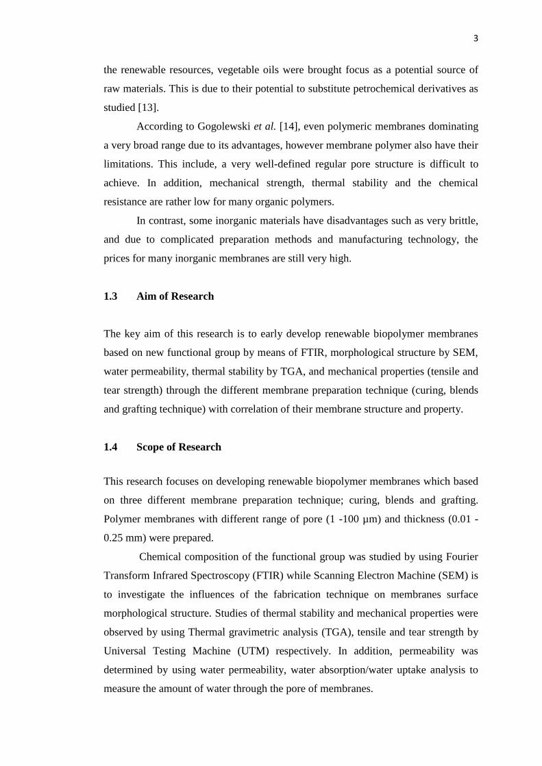
2.2 Membranes Classification
Membranes are grouped into polymeric and inorganic membranes. Membranes may
be homogeneous or heterogeneous, symmetrical or asymmetrical, and porous or non-
porous or with special chemical affinity dictated the mechanism of permeation and
separation. They also can be organic or inorganic, liquid or solid. The permeation
properties of polymer membranes are strongly influenced by both the preparative
route used and the final configuration (isotropic, asymmetric or composite) of the
membrane by studied [23]. The membrane classifications are shown in Figure 2.1.
Page 20
7
Figure 2.1: Membrane classification [22]
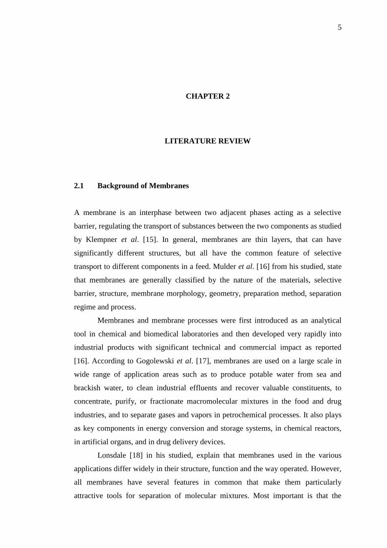
From Zhang et al. [24] studied that in essence, a membrane is nothing more
than a discrete, thin interface that moderates the permeation of chemical species in
contact with it. This interface may be molecularly homogeneous, that is, completely
uniform in composition and structure, or it may be chemically or physically
heterogeneous. Figure 2.2 shows the schematic diagrams of the principal types of
membranes.
Figure 2.2: Membrane classification according to the morphology [24]
2.2.1 Isotropic Membranes
Isotropic microporous membranes have a rigid, interconnected pore, voided and
structure distributed randomly. The separation process is controlled by the pore size
distribution of microporous membranes and the hydrodynamic conditions. The
Page 21
8
microporous membranes are prepared by phase separation, tracked etch, stretching,
or leaching. The phase separation is the most important method for the isotropic
microporous membrane preparation[25]. Figure 2.3 shows the schematic diagram of
different membrane morphologies.
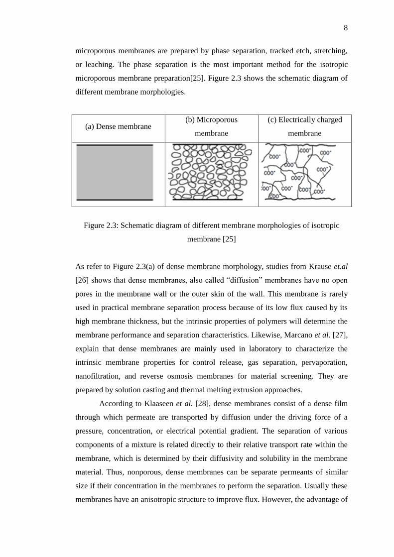
(a) Dense membrane (b) Microporous
membrane
(c) Electrically charged
membrane
Figure 2.3: Schematic diagram of different membrane morphologies of isotropic
membrane [25]
As refer to Figure 2.3(a) of dense membrane morphology, studies from Krause et.al
[26] shows that dense membranes, also called “diffusion” membranes have no open
pores in the membrane wall or the outer skin of the wall. This membrane is rarely
used in practical membrane separation process because of its low flux caused by its
high membrane thickness, but the intrinsic properties of polymers will determine the
membrane performance and separation characteristics. Likewise, Marcano et al. [27],
explain that dense membranes are mainly used in laboratory to characterize the
intrinsic membrane properties for control release, gas separation, pervaporation,
nanofiltration, and reverse osmosis membranes for material screening. They are
prepared by solution casting and thermal melting extrusion approaches.
According to Klaaseen et al. [28], dense membranes consist of a dense film
through which permeate are transported by diffusion under the driving force of a
pressure, concentration, or electrical potential gradient. The separation of various
components of a mixture is related directly to their relative transport rate within the
membrane, which is determined by their diffusivity and solubility in the membrane
material. Thus, nonporous, dense membranes can be separate permeants of similar
size if their concentration in the membranes to perform the separation. Usually these
membranes have an anisotropic structure to improve flux. However, the advantage of
Page 22
9
these membranes was their relatively high wall thickness due to mechanical
requirements.
Brieter et al. [29], from their studied explain that morphology of microporous
membrane is very similar in structure and function to a conventional filter as refer to
Figure 2.3(b). It has a rigid, highly voided structure with randomly distribute, and
interconnected pores. However, these pores differ from those in conventional filter
by being extremely small, on the order of 0.01 to 10 µm in diameter. All particles
larger than the largest pores are completely rejected by virtue of a sieving effect.
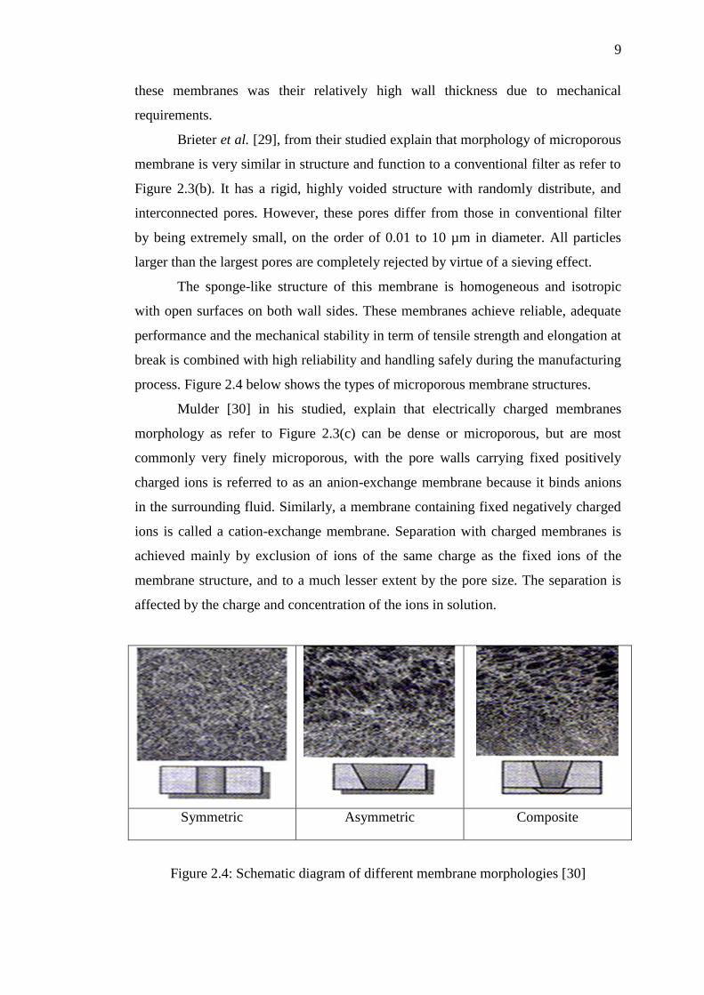
The sponge-like structure of this membrane is homogeneous and isotropic
with open surfaces on both wall sides. These membranes achieve reliable, adequate
performance and the mechanical stability in term of tensile strength and elongation at
break is combined with high reliability and handling safely during the manufacturing
process. Figure 2.4 below shows the types of microporous membrane structures.
Mulder [30] in his studied, explain that electrically charged membranes
morphology as refer to Figure 2.3(c) can be dense or microporous, but are most
commonly very finely microporous, with the pore walls carrying fixed positively
charged ions is referred to as an anion-exchange membrane because it binds anions
in the surrounding fluid. Similarly, a membrane containing fixed negatively charged
ions is called a cation-exchange membrane. Separation with charged membranes is
achieved mainly by exclusion of ions of the same charge as the fixed ions of the
membrane structure, and to a much lesser extent by the pore size. The separation is
affected by the charge and concentration of the ions in solution.
Symmetric Asymmetric Composite
Figure 2.4: Schematic diagram of different membrane morphologies [30]
Page 23
10
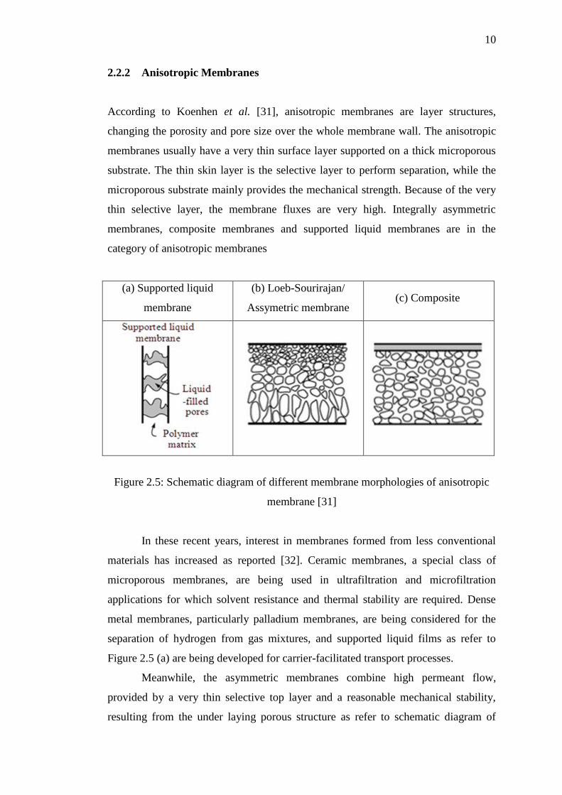
2.2.2 Anisotropic Membranes
According to Koenhen et al. [31], anisotropic membranes are layer structures,
changing the porosity and pore size over the whole membrane wall. The anisotropic
membranes usually have a very thin surface layer supported on a thick microporous
substrate. The thin skin layer is the selective layer to perform separation, while the
microporous substrate mainly provides the mechanical strength. Because of the very
thin selective layer, the membrane fluxes are very high. Integrally asymmetric
membranes, composite membranes and supported liquid membranes are in the
category of anisotropic membranes
(a) Supported liquid
membrane
(b) Loeb-Sourirajan/
Assymetric membrane (c) Composite
Figure 2.5: Schematic diagram of different membrane morphologies of anisotropic
membrane [31]
In these recent years, interest in membranes formed from less conventional
materials has increased as reported [32]. Ceramic membranes, a special class of
microporous membranes, are being used in ultrafiltration and microfiltration
applications for which solvent resistance and thermal stability are required. Dense
metal membranes, particularly palladium membranes, are being considered for the
separation of hydrogen from gas mixtures, and supported liquid films as refer to
Figure 2.5 (a) are being developed for carrier-facilitated transport processes.
Meanwhile, the asymmetric membranes combine high permeant flow,
provided by a very thin selective top layer and a reasonable mechanical stability,
resulting from the under laying porous structure as refer to schematic diagram of
Page 24
11
different membrane morphologies of anisotropic membrane in Figure 2.5(b).
According to Atala et al. [33], an asymmetric structure characterizes most of the
presently commercially available membranes, which are now produced from a wide
variety of polymers. By the most common method in generation of asymmetric
structures in membranes is the “phase-inversion” process.
Most of the presently available membranes are porous or consist of a dense
top layer on a porous structure. The preparation of membrane structures with
controlled pore size involves several techniques with relatively simple principles, but
which are quite tricky.
In Figure 2.5(c), a composite membrane is comprised of more than one
material and structure, and it also considered to belong to asymmetric membranes.
Such membranes are usually prepared by multistep method. The top and sub layer
can be originated from different polymeric materials with different structures, with
each layer able to be optimized independently. Usually, the top is a thin dense
polymer skin formed over a microporous support substrate. It can be achieved by
dip-coating, interfacial polymerization, in-situ polymerization or plasma
polymerization.
Tsui et. al [34] has summarized, usually the top layer is the active layer made
of high performance polymer that causes the separation of the solutes. This layer has
a thickness around 0.15 to 1 μm. This layer on its own has insufficient mechanical
strength and requires some support/reinforcement. As such, the desirable
reinforcement layer has to be porous material with desirable mechanical properties
and should not resist the passage of liquid. Compares with integrally asymmetric
membranes, composite membranes usually contain two separated layers with
different separation functions and different membrane materials. The porous
substrate acts as mechanical support and the skin layer is mainly used for the
selective purpose.
2.2.3 Porosity
According to Gupta et al. [35], filtration media in various forms including
membranes, woven, nonwoven and particulate beds are used extensively in a wide
variety of applications in areas such as biotech, health care, pharmaceutical, food and
beverage, power sources and chemical industries. The performance of filtration
Page 25
12
media in all of these industries is determined by the pore structure characteristics of
the media.
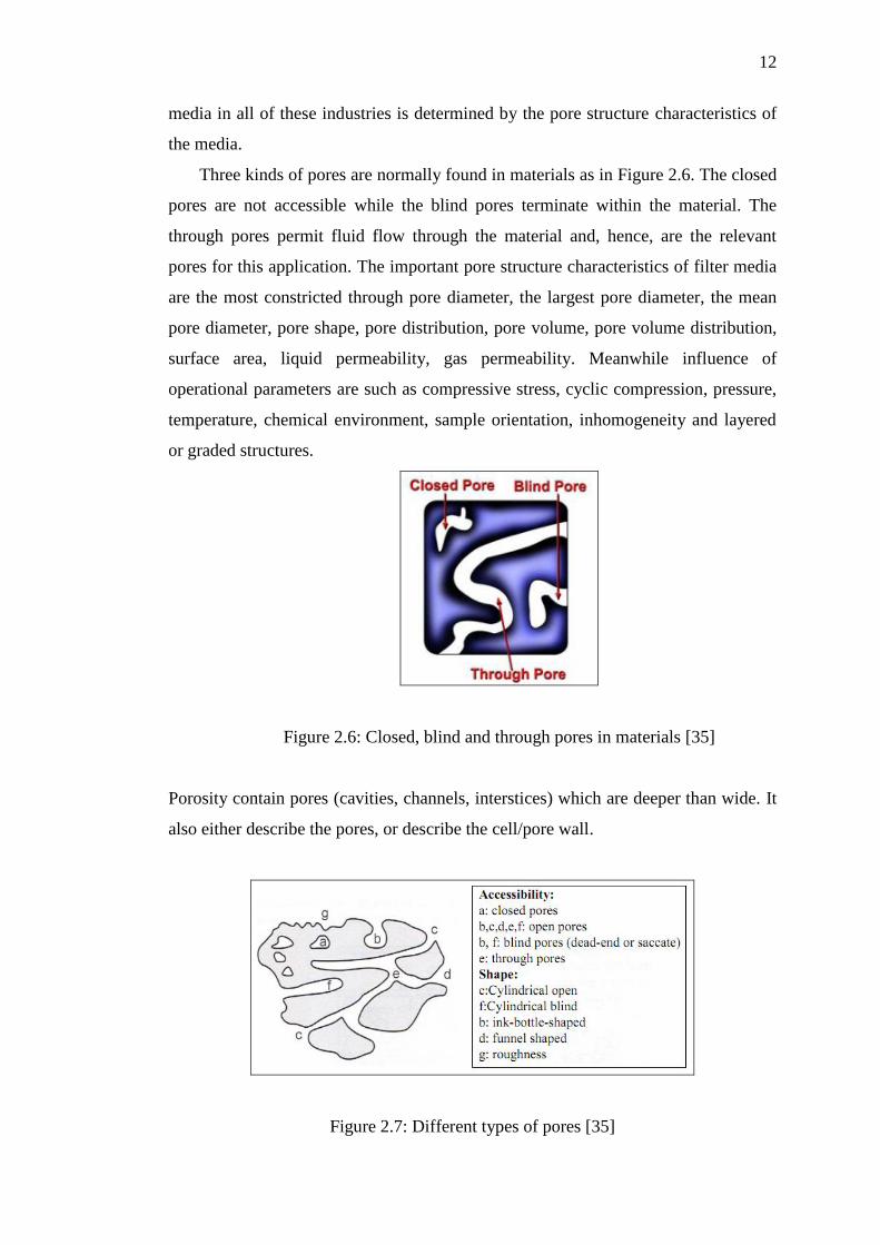
Three kinds of pores are normally found in materials as in Figure 2.6. The closed
pores are not accessible while the blind pores terminate within the material. The
through pores permit fluid flow through the material and, hence, are the relevant
pores for this application. The important pore structure characteristics of filter media
are the most constricted through pore diameter, the largest pore diameter, the mean
pore diameter, pore shape, pore distribution, pore volume, pore volume distribution,
surface area, liquid permeability, gas permeability. Meanwhile influence of
operational parameters are such as compressive stress, cyclic compression, pressure,
temperature, chemical environment, sample orientation, inhomogeneity and layered
or graded structures.
Figure 2.6: Closed, blind and through pores in materials [35]
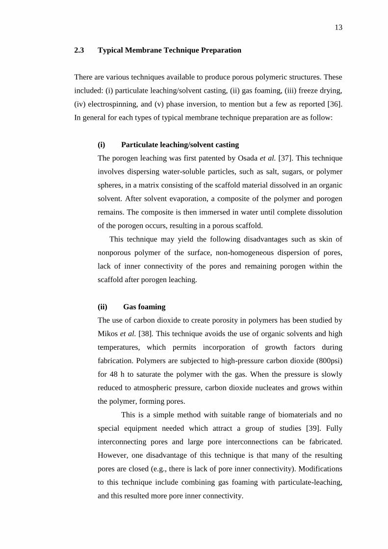
Porosity contain pores (cavities, channels, interstices) which are deeper than wide. It
also either describe the pores, or describe the cell/pore wall.
Figure 2.7: Different types of pores [35]
Page 26
13
2.3 Typical Membrane Technique Preparation
There are various techniques available to produce porous polymeric structures. These
included: (i) particulate leaching/solvent casting, (ii) gas foaming, (iii) freeze drying,
(iv) electrospinning, and (v) phase inversion, to mention but a few as reported [36].
In general for each types of typical membrane technique preparation are as follow:
(i) Particulate leaching/solvent casting
The porogen leaching was first patented by Osada et al. [37]. This technique
involves dispersing water-soluble particles, such as salt, sugars, or polymer
spheres, in a matrix consisting of the scaffold material dissolved in an organic
solvent. After solvent evaporation, a composite of the polymer and porogen
remains. The composite is then immersed in water until complete dissolution
of the porogen occurs, resulting in a porous scaffold.
This technique may yield the following disadvantages such as skin of
nonporous polymer of the surface, non-homogeneous dispersion of pores,
lack of inner connectivity of the pores and remaining porogen within the
scaffold after porogen leaching.
(ii) Gas foaming
The use of carbon dioxide to create porosity in polymers has been studied by
Mikos et al. [38]. This technique avoids the use of organic solvents and high
temperatures, which permits incorporation of growth factors during
fabrication. Polymers are subjected to high-pressure carbon dioxide (800psi)
for 48 h to saturate the polymer with the gas. When the pressure is slowly
reduced to atmospheric pressure, carbon dioxide nucleates and grows within
the polymer, forming pores.
This is a simple method with suitable range of biomaterials and no
special equipment needed which attract a group of studies [39]. Fully
interconnecting pores and large pore interconnections can be fabricated.
However, one disadvantage of this technique is that many of the resulting
pores are closed (e.g., there is lack of pore inner connectivity). Modifications
to this technique include combining gas foaming with particulate-leaching,
and this resulted more pore inner connectivity.
Page 27
14
(iii) Freeze drying
Gorna et al. [40] shows, the freeze-drying technique involves creating an
emulsion by homogenizing a polymer solvent solution and water. The
mixture is then rapidly quenched in liquid nitrogen, and the solvent and water
are removed by freeze-drying. Control of processing parameters, such as
volume fraction of the dispersed phase, results in control of the porosity.
Advantages of this technique include the ability to control pore size
from 15 to 200 microns, the ability to obtain more than 90%, and the
possibility of incorporating growth factors within the scaffolds.This technique
has been utilized many biocompatible polymers, including PGA, PLLA,
PLGA, and PPF blends. Inclusions of polymers like PPF in composite
scaffolds is beneficial for adjustment of compressive strength and properties
related to hydrophobicity.
According to Holannder et al. [41], this is a simple method with
suitable range of biomaterials and no special equipment needed. Fully
interconnecting pores and large pore interconnections can be fabricated. No
organic solvents are required. Some researcher using this method to studied
about nanopowder of rare earth tungsten for emission materials.
(iv) Electrospinning
Studied from [42], a modern method for creating porous scaffolds composed
of nano and microscale biodegradable fibers employs electrostatic fiber
spinning, or electrospinning, a technology derived from the electrostatic
spraying of polymer coatings. This method had been used by to form
microporous, non-woven poly(e-caprolactone) (PCL) scaffolds.
(v) Phase inversion
Kaushiva et al. [43] studied, phase inversion is a process one-phase solution
containing the membrane polymer transformed by a
precipitation/solidification process into two separate phases into separate
phases (a polymer-rich solid and polymer-lean liquid phase) as reported [43].
This process is most common used in generation of asymmetric structure in
membranes.
Page 28
15
According to Bhattacharya et al. [45], the effect of surface properties on the
biocompatibility of biomaterials based on the same material; polyurethane
membranes with different surface properties were prepared. Phase inversion
technique was using as a method to fabricate the membranes. Ulbricht [46] reported
that microporous membranes with controlled pore size and structure were produce
from biodegradable polyurethane by using the modified phase inversion technique in
some studies.
In other cases, some researcher use two different types of phase inversion
technique which consisted wet phase inversion method and dry phase inversion
method to produces two different types of membranes (asymmetric and dense film).
The in-vitro response of human platelets was studied upon adherence to
films/membranes of polyurethane with different soft segments was studied [47].
Chalida et al. [48] has summarized, typically for membranes prepared by
phase inversion procedure, the properties of casting polymer solution have
significant influence on the structure of the resultant membranes. The more viscous
the solution, the smaller exchange rate between nonsolvent and solvent in polymer
film solution due to the rheological hindrance, thus resulting in membrane structure
with smaller pore size.
Most established membrane polymers however were not meet all the
performance requirements for a membrane dedicated to a particular application,
therefore membrane modifications are gaining rapidly increasing importance.
Acording to Chalida et al. [48] in his studied, based on the preparation of porous ion-
exchanged membranes with their characterizations was summarized that from
conventional precipitation method which by immersing the nascent polymer
membrane the nascent polymer film directly into water bath which casting solution
was took around 1min to form nascent film at room temperature.
As shown in Figure 2.6, sPES membranes with different porosities were
synthesized using a so-called phase inversion process, namely wet phase inversion
(precipitation), or dry phase inversion (solvent evaporation), or the combination of
these two processes. The membrane obtained from conventional precipitation
method by immersing the nascent polymer film directly into water bath (it took
casting solution around 1 min to form nascent film at room temperature.
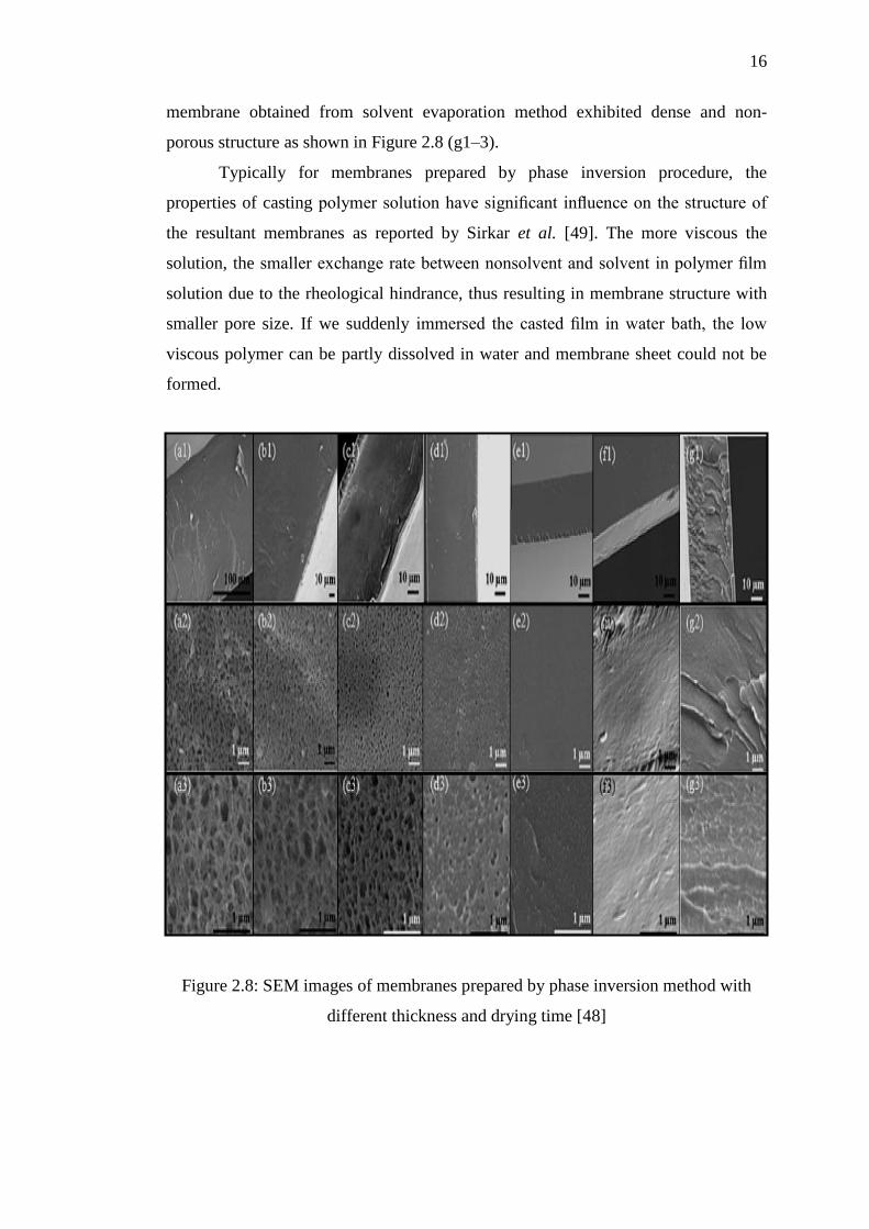
As refer to Figure 2.8, (a1–3) was highly porous with largest pore size
compared to membranes prepared under other conditions. On the other hand, the
Page 29
16
membrane obtained from solvent evaporation method exhibited dense and non-
porous structure as shown in Figure 2.8 (g1–3).
Typically for membranes prepared by phase inversion procedure, the
properties of casting polymer solution have significant influence on the structure of
the resultant membranes as reported by Sirkar et al. [49]. The more viscous the
solution, the smaller exchange rate between nonsolvent and solvent in polymer film
solution due to the rheological hindrance, thus resulting in membrane structure with
smaller pore size. If we suddenly immersed the casted film in water bath, the low
viscous polymer can be partly dissolved in water and membrane sheet could not be
formed.
Figure 2.8: SEM images of membranes prepared by phase inversion method with
different thickness and drying time [48]
Page 30
17
2.4 Membrane Modification
According to Guo et al. [50], the parameter affecting the process of membranes such
as type of solvent, solvent-nonsolvent ratio, polymer concentration in solution,
polymer solidification time, and thickness of the polymer solution layer cast on a
substrate were investigate. The phase inversion process consists of the induction of
phase separation in a previously homogeneous polymer solution either by
temperature change, by immersing the solution in a non-solvent bath (wet process) or
exposing it to a non-solvent atmosphere (dry process).
As reported by Seymour et al. [51], in the thermal process, a low molecular
weight component usually acts as a solvent at high temperature and as a non-solvent
at low temperature. It is then removed after formation of the porous structure.
Usually the polymer solution is immersed in a non-solvent bath and a solvent-non-
solvent exchange leads to phase separation. The polymer-rich phase forms the porous
matrix, while the polymer-poor phase gives rise to the pores. The morphology is
usually asymmetric, with a selective skin on the surface.
The discussion so far implies that membrane materials are organic polymers
and,in fact, the vast majority of membranes used commercially are polymer-
based.Furthermore, polymeric membranes were dominating a very broad range of
industrial applications due to their following advantages:
(i) different types of polymeric materials are commercially available
(ii) a large variety of different selective barriers: porous, nonporous, charged and
affinity, can be prepared by versatile and robust methods
(iii)production of large membrane area with consistent quality is possible on the
technical scale at reasonable cost based on reliable manufacturing processes
(iv) Various membrane shapes (flat sheet, hollow-fiber, capillary, tubular, capsule
and formats including membrane modules with high packing density modules
can be produced.
Therefore, membrane modification is aimed either to minimize undesired
interactions, which reduce membrane performance (e.g., membrane fouling), or to
introduce additional interactions (e.g., affinity, responsive or catalytic properties) for
improving the selectivity or creating and entirely novel separation function. An
Page 31
18
increasing number of methods and technologies investigated for polymer surfaces in
general are now being adapted to surface fuctionalization of polymeric membranes in
studied by Szwarc [52].
A key feature of a successful surface modification is a synergy between the
useful properties of the base membrane and the novel functional layer. In order to
achieve a stable effect, chemical modification is preferable over physical
modification. Attachment of functional moieties onto a membrane surface by
physical principles can be done via following ways:
(i) Adsorption/adhesion – the functional layer is only physically fixed on the
base material, and the binding strength can be increased via multiple
interactions between functional groups in the macromolecular layer and on
the solid surface.
(ii) Interpenetration via mixing between the added functional polymer and the
base polymer in an interphase.
(iii)Mechanical interpenetration (macroscopic entanglement) of an added
polymer layer and the pore structure of a membrane.
There are several means to modify polymer properties such as blending,
grafting, and curing: (a) Blending is the physical mixture of two (or more) polymers
to obtain the requisite properties, (b) Curing is polymerization of an oligomer
mixture forms a coating which adheres to the substrate by physical forces, and (c)
Grafting is a method wherein monomers are covalently bonded (modified) onto the
polymer chain as summarized by Kuitian et al. [53]. Curing gives a smooth finish by
filling in the valleys in the surface. The schematic representation of the above
membrane modification method is as refer to Figure 2.9.
Page 32
19
Figure 2.9: Schematic representation of the methods of polymer modification [53]
(a) Blending
According to Kuitian et al. [54], polymer blends are defined as combination
and intimate mixtures of two kinds of two kinds of polymer, with no covalent
bonds between them. In most cases, blends are homogeneous on scales larger
than several times the wavelengths of visible light. While in principle, the
constituents of a blend are separable by physical means. Material prepared in
historically usually contain several percent of elastomer, dispersed in plastic
matrix, the plastic component predominates.
There are four basic of conception in which the principal methods of
mixing two kinds of polymer molecules include; (a) mechanical blending, (b)
graft copolymerization, (c) block copolymerization and (d) interpenetration of
polymer network. Therefore, the most important characteristic of a polymer
blend of two (or more) polymers is the phase behavior in which two basic
types of polymer blends; (a) miscible and (b) immiscible as summarized by
Kim et al. [55].
Miscibility in the context of polymer blends is defined as the degree
of mixing yield properties such as glass transition temperature and
permeability, expected of a single phase material. It may be homogeneous
Page 33
20
down to the molecular level and associated with the negative value of the free
energy of mixing and the domain sizes comparable to the dimensions of the
macromolecular statistical segment. Concentration fluctuations of miscible
polymers would be expected to be of the order of several nanometer. In fact,
many blends noted to be miscible show structure of the order of several
nanometers when sensitive method [55].
In contrast, the vast majority of polymer pairs are immiscible with one
another. There are only few commercially important polymer blends based on
miscible and partially miscible (such as miscible within a low range of
concentration) polymer pairs. It is seldom possible to mix two or more
polymers and create a blend with useful properties [55].
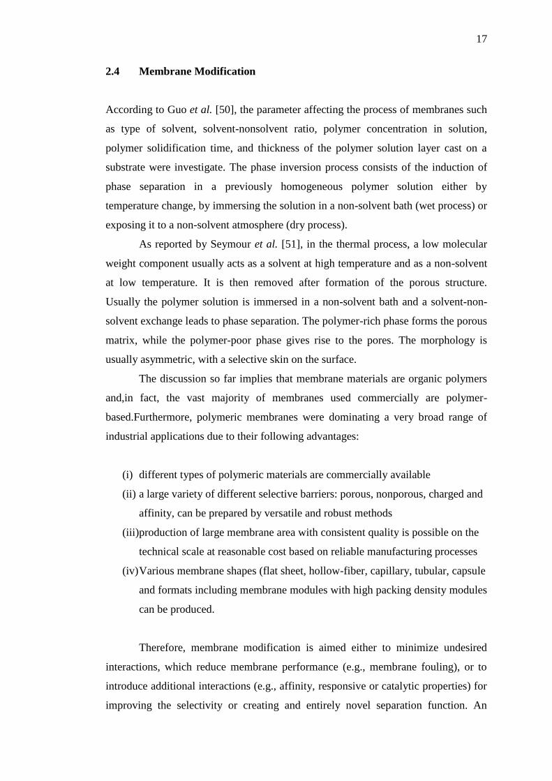
Figure 2.10: SEM images that showed the effect of blending of chitosan with
PEG on membrane surface morphology [55]
According to Anbarason et al [56] in his studied about the effect of
blending of chitosan with PEG on surface morphology and crystallization, it
is well know that chitosan molecules are quite rigid, and the condition of
sample preparation normally has marked effect on crystallization. Through
this reason, chitosan film could present branch crystal, spherulites an so on.
Since both chitosan and PEG are crystalline structure polymers, they
may interact with each other in a certain manner so that the original
crystalline structures of each component have been disturb odor partially
damaged to a different extend, leading to various crystalline structures of the
blend film.
Page 34
21
At first, pure chitosan appeared as a slender acicular structure
dispersed homogenously as shown in Figure 2.10 (a). With addition of PEG,
the surface structure changed markedly. The surface of chitosan appeared
more smooth and uniform, in which with addition of PEG as shown in Figure
2.10 (b), the surface of blend film displayed some irregular holes. As a result
of migration, many holes were generated on the surface of blend film.
Figure 2.11: Morphology of PVDF/PEO-b-PMMA polymer
membranes [56]
Likewise, Anbarason et al. [57] in his study about the formation of
pores is dependent on the mass fraction of PEO-b-PMMA, membranes shows
exhibit a large number of small pores as shown in Figure 2.11 (a), but then
the pore distribution on the surface of membrane becomes denser with
increase of PEO-b-PMMA as shown in micrograph (e). This can be attributed
to the high porosity of PVDF/PEO-b-PMMA blend macroporous membranes,
in which the pores in the bulk of the membranes are not well interconnected
find when PEO-b-PMMA content is low as shown in Figure 2.11 (a–c).
However, the pores become well interconnected when the mass
fraction of PEO is about 30% as shown in Figure 2.11 (d). In the solution of
Page 35
22
PVDF/DMF/glycerin, with the evaporation of DMF (solvent), the phase
separation between PVDF and glycerin (non-solvent) forms a polymer-rich
phase and a polymer-poor phase. The former finally forms the polymer
matrix, while the latter forms the porous structure.
Instead, when preparing a new polymer blend from immiscible resins,
it is necessary to devise a specific strategy for compatibilizing the mixture to
provide for optimum physical performance and long-term stability. Although
there do exist a very small number of commercial blends of immiscible
polymers that are not compatibilized, most commercially available blends of
immiscible polymers have been compatibilized by some specific mechanism.
Polymer blends like low molecular weight solvents can exhibit
miscibility or phase separation and various levels of mixing in between the
extremes such as partial miscibility. The most important factor leading to
miscibility in low molecular weight materials is the combinatorial entropy
contribution which is very large compared to high molecular weight
polymers. This contribution is the reason that solvent-solvent mixtures offer a
much broader range of miscibility than polymer-solvent combinations. The
range of miscible combinations involving polymer-polymer mixtures is even
much smaller [58-59].
Due to some disadvantages such as poor mechanical properties of
polymers from renewable resources, or to offset the high price of synthetic
biodegradable polymers, various blend and have been developed. Blends
comprises of three kinds of polymers from renewable resources [60]:
(i) Natural polymers, such as starch, protein and cellulose.
(ii) Synthetic polymers from natural monomers, such as polylactic acid.
(ii) Polymers from microbial fermentation, such as polyhydroxybutyrate
are described with an emphasis on potential applications.
The majority of polymer blends containing elastomeric, thermoplastic,
liquid crystalline polymers are processed by melt extrusion at some point.
After melt extrusion with intensive mixing, the morphology of an immiscible
polymer blend on a microscopic scale will often consist of a dispersed phase
of the more viscous polymer in a continous matrix of less viscous polymer
Page 36
23
depending upon relative amounts and viscosities of the two polymers in blend
as referred to Wang et al. [61].
The formation of optimum dispersed phase particle size and long-term
stabilization of blend morphology are critical if the blends is to have optimum
properties and in particular good mechanical properties. If this morphology is
not stabilized, then the dispersed phase may coalesce during any subsequent
heat and high stress treatment such as injection molding [62].
According to Samal et al. [63], an important aspect of all
compatibilization strategies is the promotion of morphology stabilization. It
be provided by sufficient interfacial adhesion and lowered interfacial tension
between the two polymer phases of the various compatibilization strategies
that have been devised an increasingly common method is either to add a
block, graft, or crosslinked copolymer of the two (or more) separate polymers
in the blend or to form such copolymer through covalent or ionic bond
formation during “Reactive Compatibilization” step.
Blends are usually made in two ways; (1) The first way is to dissolve
two polymers in the same solvent, and the (2) second way wait for the solvent
to evaporate and just eft with a blend at the bottom in beaker, presuming that
two polymers are miscible.
According to Bhattacharya [64], the basic strategies for “Reactive
Compatibilization” of two-phase polymer blends can divide into at least three
major categories:
(i) Co-crystallization of two phases
This particular strategy is limited to those cases in which an immiscible
polymer blend contains two semi-crystallize. It may also occur as a secondary
process in an intimately mixed blend containing a copolymer with
concomitant effects on blend properties [65].
(ii) In situ Immobilization of one phase: Dynamic Vulcanization
In these cases, a dispersed phase of cross linkable rubber is vulcanizable in
the presence of a matrix of a second, immiscible, non-vulcanizable polymer
during the residence time of melt processing. There are five key requirements
for preparing optimum composition by dynamic vulcanization [66].
Page 37
24
(i) Good match between surfaces energies of the dispersed phase and the
matrix.
(ii) Low entanglement molecular length (high entanglement density) of
the rubber.
(iii) Crystalline plastic matrix.
(iv) Stable rubber and plastic at blend processing
(v) Availability of appropriate curing system for rubber under desired
processing conditions.
(iii) Addition of a third material as a compatibilizing agent
There are two basic options for addition of a copolymer compatibilizer to a
blend of immiscible polymers:
Addition of a separate compatibilizing agent
The copolymer can be synthesized in a separate step followed by addition to
the blend. It may be a third material which not derived from either of the
two immiscible polymers. This is also chemically unreactive analog of one or
both of the two immiscible polymers that has an attractive interaction with
each polymer [67].
Addition of a copolymer of the two immiscible polymers
Adding a copolymer to a blend of immiscible polymers is to form the
copolymer in situ which most economical and efficient process for a chemical
reaction during the extrusion process during establishment of the immiscible
phase morphology (Reactive Compatibilization).
Sanli et al. [68] reported that this manner is very ideal suited to act as
compatibilizing agent for an immiscible blend, where if the copolymer is at
the interface of the two phases, then the segments of the copolymer dissolve
in the respective bulk phases of the same identity. The copolymer acts as
emulsifying agent for the blend resulting in reduced interfacial energy and
improved interphase adhesion.
Page 38
102
REFERENCES
1. Gogolewski, S.,Pennings, A.J., Lommen, E., Wildevuur, C.R.H. and
Neuwenhius, P. Growth of a Neo-Artery Induced by a Biodegradable
Polymeric Vascular Prosthesis. Makromolecular Chemical Rapid
Communications. 1983. 4(4): 213-219.
2. Baker, R.W. Membrane Technology and its Application. 2nd Edition. Menlo
Park California. John Wiley & Son. 2004.
3. Suprakas, S.R. and Bousmina, M. Biodegradable Polymers and Their
Layered Silicate Nanocomposites: In greening the 21st century materials
world. Progress in Materials Science. 2005. 50(8): 962–1079.
4. Walpoth, B.H., Rheiner, P., Cox, J.N., Faidutti, B., Megevand, R. and
Gogolewski, S. Implantations Chroniques De Membranes Et Protheses En
Polyurethanes. Helvetica Chimica Acta. 1988. 55(1-2): 62-157.
5. Heidi, L., Schreuder, G., Quoc, T., John, E., Walker, J.R., Joseph, D., Wander
and Wayne, E.J. Chemical and Biological Protection and Detection in Fabrics
for Protective Clothing. Materials Research Society. 2003. 28(8): 574-5
6. AnikaZafiah, M.R. Effect of Titanium Dioxide on Material Properties for
Renewable Rapeseed and Sunflower Polyurethane. International Journal of
Integrated Engineering (Issues on Mechanical, Materials and
Manufacturing Engineering. 2009a. 1: 15-22.
7. AnikaZafiah, M.R. Degradation Studies of Polyurethanes Based on Vegetable
Oils. Part 2; Thermal. Degradation and Materials Properties. Progress
Reaction Kinetic and Mechanism, Science Reviews. 2009b. 34: 1-43.
8. AnikaZafiah, M.R. (2010): Polymer from Renewable Materials, Science
Progress. 2010. 93(3): 285-300.
9. Sin, D.C., Miao, X., Liu, G., Wei, F., Chadwick, G., Yan, C. and Friis, T.
Polyurethane (PU) Scaffolds Prepared by Solvent Casting/Particulate
Leaching (SCPL) Combined with Centrifugation. 2009.
Page 39
103
10. Strathmann, H. Production of Microporous Media by Phase Inversion
Process. In: Lloyd DR, Editor. Materials Science of Synthetic Membranes.
Washington, DC: American Chemical Society. pp; 65-195;1987
11. Lucas, M.D.E., Michael, A.R. and Meier. Plant oils: The Perfect Renewable
Resource for Polymer Science. European Polymer Journal. 2011. 47: 837–
852.
12. Huayu, T., Zhaohui, T., Xiuli, Z., Xuesi, C. and Xiabin, J. Biodegradable
Synthetic Polymers: Preparation, Functionalization and Biomedical
Application. Progress in Polymer Science. 2012. 37: 237– 280.
13. (a) Meier, M.A.R., Metzger, J.O. and Schubert, U.S. Plant oil renewable
resources as green alternatives in polymer science. Chemical Social. 2007.
36:802-1788; (b) Metzger, J.O. Fats and Oils as Renewable Feedstock for
Chemistry. European J. Lipid Science Technology. 2009. 111(9): 76-865.
14. Gogolewski, S., Walpoth, B. and Rheiner, P. Polyurethane microporous
membranes as pericardial substitutes. Colloid Polymer Science. 1987.
265(11): 7-971.
15. Klempner, D. and Frisch, K.C. The Handbook of Polymeric Foams and Foam
Technology. Munich, Germany. Hauser. 1991.
16. Mulder, M. Basic Priciples of Membrane Technology. Netherlands. Kluwer
Academic, Dodrecht. 1991.
17. Walpoth, B.H., Rheiner, P., Cox, J.N., Faidutti, B., Megevand, R. And
Gogolewski, S. Implantations chroniques de membranes et protheses en
polyurethanes. HelvChirActa. (1988); 55(1-2): 157-62.
18. Lonsdale, H.K. The Growth of Membrane Technology. Journal Membrane
Science. 1982. 10: 81-181.
19. Drioli, E. and Romano, M. Progress and New Perspectives on Integrated
Membrane Operations for Sustainable Industrial Growth. Industry
Engineering Chemical Research. 2001. 40: 1277.
20. Bhattacharyya, D. and Butterfield, D.A. Amsterdam. New Insights into
Membrane Science and Technology:Polymeric and Biofunctional
Membranes. Elsevier. 2003.
21. Zeman, L.J. and Zydney, A.L. Microfiltration and Ultrafiltration:Principles
and Applications. New Yok.Marcel Dekker Inc. 1996.
Page 40
104
22. Drioli, Z.E. and Giorno, L. Biocatalytic Membrane Reactors: Aplication in
Biotechnology and the Pharmaceutical Industry. London, UK.Taylor &
Francis Publisher. 1999.
23. Ho, W. and Sirkar, K.K. Membrane Handbook. New York. Van Nostrand
Reihnold Publisher. 1992.
24. Zhang, R., and Ma, P.X. Porous Poly(L-Lactic Acid)/Apatite Composites.
Biomimetic Process Journal Biomedical Material. 1999.45: 285.
25. Witte, P.V., Dijkstra, P.J, Berg J.W.A. and Feijen, J. Phase separation
Processes in Polymer Solutions in Relation to Membrane Formation. Journal
Membrane Science. 1996. 117: 1–31.
26. Krause, B., Gohl, H. and Wiese, F., Ohlrogge, K. and Ebert K. Membrane.
Weinheim Wiley-VCH. 2006.
27. Marcano, J.S. and Tsotsis, T.T. Catalytic Membranes and Membrane
Reactors. Weinhem Wiley-CVH. 2002.
28. Klaaseen R., Feron, P.H.M and Jansen, A.E. Membrane Contactor in
Industrial Aplication. Trans Icheme Part A. Chemical Engineering Research
and Design. 2005. 83(A3): 234-246.
29. Breiter, S. M., Wiese, F., Wodetzki, A. and Schuster, O. Membrane
Technology: Membrane for Life Science. ASAIO Journal, 2004. 50:153.
30. Mulder, M. Basic Principles of Membrane Technology: 2nd
edition. Springer.
1996.
31. Koenhen, D. M., Mulder, M.H.V. and Smolders, C.A. Phase separation
phenomena during the formation of asymmetric membranes. Journal Applied
Polymer Science. 1997. 21(1): 199-215.
32. Lanza, R.P. And Vacanti, J. Principles of Tissue Engineering; Edition 3:
Academic Press. USA. 2007.
33. Atala, A. and Lanza, R.P. Methods of Tissue Engineering. United States of
America: Elsevier. 2002.
34. Tsui, Y.K. And Gogolewski, S. Microporous Biodegradable Polyurethane
Membranes for Tissue Engineering. Jornal Material Science: Material
Medical. 2009. 20:1729-1741.
35. Gupta, K.M and Jena, A.K. Pore Size Distribution in Porous Materials.
Proceedings of International Conference Filtration (3-4 November 1999).
Chicago, INDIA, 1999 .
Page 41
105
36. Manole, A.V., Melnig, V., Zonda, R., Vacareanu, C. and Chiper, S. A. In-
Vitro Evaluation of Platelet Adhesion on Polyurethane Films and
Membranes. Romanian Journal Biophysical. 2008. 18(1): 29–37.
37. Osada, Y. and Nakagawa, T. Membrane Science and Technology. Marcel
Dekker Inc. 1992.
38. Mikos, A.G. and Temenoff, J.S. Formation of Highly Porous Biodegradable
Scaffolds for Tissue Engineering. Electronic Journal Biotechnol. 2000. 3(2):
9-114.
39. Xi, X., Nie, Z., Yang, J., Fu, X., Ji, D., and Zuo, T. Preparation and
Characterization of Non powder of Emission Materials by Freeze-Drying.
Journal of Nanoscience and Nanotechnology. 2005. 24(3): 199-272.
40. Gorna, K. and Gogolewski, S. Porous Biodegradable Polyurethane Scaffolds
for Tissue Repair and Regeneration. Journal Biomedical Material Research.
2006;79A(1): 128–38.
41. Hollander, A.P. and Hatton, P.V. Biopolymer Methods in Tissue
Engineering. Molecular Biology: Human Press. United Kingdom. Vol 238.
2004.
42. Yoshimoto, H., Shin, Y.M., Terai, H. and Vacanti, J.P. A Biodegradable
Nanofiber Scaffold by Electrospinning and its Potential for Bone Tissue
Engineering. Biomaterials. 2002. 24:2077-2082.
43. Kaushiva, A., Turzhitsky, V.M., Backman, V. and Ameer, G.A. A
Biodegradable Vascularizing Membrane: A Feasibility Study. Acta
Biomaterial. 2007. 3:631–642.
44. Kato, K., Uchida, E., Kang E., Uyama, Y. and Ikada, Y. Progress in Polymer
Science. 2003. 28: 209-259
45. Sperling, L.H. Introduction to Physical Polymer Science. 4th
ed. New Jersey:
John Wiley & Sons, Inc. 2006.
46. Ulbricht, M. Polymer. 2006. 47: 2217-2262.
47. Bhattacharya, A. Radiation and Industrial Polymers. Progress Polymer
Science. 2000. 25: 371–401.
48. Chalida, K., Seung H.M., Bradley, P., Ladewiga,, C.G.Q., Max, L. and
Lianzhou, W. Preparation of Porous Ion-Exchange Membranes (Iems) And
Their Characterizations. Journal of Membrane Science. 2011. 371: 37–44.
Page 42
106
49. Sirkar, K.K., Winston, and Ho A.S. Membrane handbook. New York. Van
Nostrand Reinhold. 1992.
50. Guo, Y.Q., Tong, Z., Chen, M.C and Liang, X.H. Phase change behavior of
Polyethelene Glycol. Polymer Material Science Engineering. 2003. 19(5):
53-149.
51. Seymour, R.W., and Cooper, S. L. Thermal analysis of polyurethane block
polymers. Macromolecules 1973;6:48–53.
52. Szwarc M. Living Polymers:Their Discovery, Characterization and
Properties. Journal Polymer Science Part A: Polymer Chemical. 1998. 36: 9–
95.
53. Kuitian, T. and Obendorf, S.K. Surface Modification of Micro-porous
Polyurethane Membrane with Polyethylene glycol to Develop a Hybrid
Membrane. Journal of Membrane Science. 2006. 274(1-2): 150-158.
54. Kuitian, T. and Obendorf S.K. Hybrid Microporous Membranes Intended for
Protective Clothing, 15th
National Textile Center Conference. February 25-
27. Hilton Head Island, South Carolina. 2007.
55. Kim, M.J., Sea, B., Youn, K.H., and Lee, K.H. Morphology and Carbon
Dioxide Transport Properties of Polyurethane Blend Membranes.
Desalination. 2005. 193:43-50.
56. Anbarason, R., Jayasehara, J., Sudha, H., Nirmala, P.V. and Gopalon, A.
Peroxosalts Initiated Graft Copolymerization of O-Toluidine Onto Rayon
Fibre:A Kinetic Approach. Journal Polymer Material. 2000. 48(2): 199–223.
57. Anbarason, R., Jayasehara, J., Sudha, H., Nirmala, P.V. and Gopalon, A.
Peroxydisulphate Initiated Graft Copolymerization of O-Toluidine Onto
Synthetic Fibers—A Kinetic Approach. Applied Makromolecular Chemistry
and Physic. 2000. 201: 76-1869.
58. Celik, M. and Sacak, M. The Rate of Grafting and Some Kinetic Parameters
of the Graft Copolymerization of Methacrylic Acid on Poly(Ethylene
Terephthalate) Fibers With Azobisisobutyronitrile. Turkey Journal Chemical.
2000. 24(3): 74-269.
59. Bhattacharyya, S.N. and Maldas, D. Graft Copolymerization Onto
Cellulosics. Progress Polymer Science. 1983. 10: 171–270.
Page 43
107
60. Khalil, M.I., Rafie E.M.H., Bendak, A. and Hebeish, A. Graft Polymerization
of Methylmethacrylate Onto Wool Using Dimethylaniline/Cu(II) System.
Cellulose Chemistry and Technology 1982. 16(5): 71- 465.
61. Wang, M., Wu, L.G, Mo, J.X., and Gao, C.J.C. The Preparation and
Characterization of Novel Charged Polyacrylonitrile/PES-C Blend
Membranes Used for Ultrafiltration. Journal Membrane Science. 2006. 274:
200–208.
62. Sun, T., Xu, P., Liu, Q., Xue, J. and Xie, W. Graft Copolymerization of
Methacrylic Acid onto Carboxymethyl Chitosan. European Journal Polymer.
2003. 39: 92-189.
63. Samal, S., Sahu, G., Lenka, S. and Nayak, P.L. Photoinduced Graft
Copolymerization (XI):Graft Copolymerization of Methylmethacrylate onto
Silk using Isoquinoline-sulphur Dioxide Charge Transfer Complex as the
Initiator. Journal Applied Polymer Science. 1987. 33(5): 8-1853.
64. Tang, Z.G. and Teoh, S.H. Microstructural Evaluation of an Elastomeric
Composite Membrane from Two Immiscible Polymers (UHMWPE and
polyurethane) for Soft Tissue Replacement, Colloids Surface B:
Biointerfaces. 2000: 19.
65. Wang, M., Wu L.G, Mo, J.X, Gao, C.J. The Preparation and Characterization
of Novel Charged Polyacrylonitrile/PES-C Blend Membranes used for
Ultrafiltration. Journal Membrane Science. 2006.274: 20–200
66. Cheriyan, M. Ultrafiltration and Microfiltration Handbook. USA: Technmic
Publishing Company. 1998: 9.
67. Tang, J.X., He, N.Y., Tan, M..J., He, Q.G and He, H.C, A Novel Substrate
For In Situ Synthesis of Oligonucleotide: Plasma-Treated Polypropylene
Microporous Membrane, Colloids Surface A. Physicochemical Engineering
Aspects. 2004. 242: 53.
68. Sanli, O. and Pulet, E., Solvent Assisted Graft Copolymerization of
Acrylamide on Poly(Ethylene Terephthalate)Films Using Benzoyl Peroxide
Initiator. Journal Applied Polymer Science. 1993. 47 :1–6.
69. Yamaki, T., Asano, M., Maekawa, Y., Morita, Y., Suwa, T., Chen, J.,
Tsubokawa, N., Kobayashi, K., Kubota, H. and Yoshida, M. Radiation
Grafting of Styrene Into Crosslinked PTFE Films and Subsequent Sulfonation
for Fuel Cell Applications. Radiation Physic and Chemistry. 2003. 67: 7-403.
Page 44
108
70. Kaur, I., Barsola, R., Gupta, A. and Misra, B.N. Graft Copolymerization Of
Acrylonitrile and Methacrylonitrile onto Gelatin by Mutual Irradiation
Method. Journal Applied Polymer Science. 1994. 54: 9-1131.
71. Kaur, I., Misra, B.N., Chauhan, M.S, Chauhan, S. and Gupta, A. Viscometric,
Conductometric and Ultrasonic Studies of Gelatin-G-Polyacrylamide
Composite. Jornal Applied Polymer Science. 1996. 59: 97-389.
72. Kaur, I., Misra, B.N., Barsola, R. and Singla, K. Viscometric Studies of
Starch-G-Polyacrylamide Composites. Jornal Applied Polymer Science.
1993. 47: 74-1165.
73. Coessens V, Pintauer T, and Matyjaszewski K. Functional Polymers by Atom
Transfer Radical Polymerization. Progress Polymer Science. 2001. 26(7): 7-
337.
74. Zhang, R., and Ma, P.X. Poly(Alpha-Hydroxy Acids)/Hydroxyapatite Porous
Composites for Bone Tissue Engineering: 1. Preparation and Morphology.
Jornal Biomedical Material Research. 1999. 44:446
75. Schamberg, E. and Hoigne, J. Radical And Radiation-Induced Grafting of
Some Synthetic High Polymers Within the Temperature Range of Their Glass
Transition. Journal Polymer Science Part A: Polymer Chemistry. 1970. 8: 8-
693.
76. Stehling, U.M., Malmstrom, E.E., Waymouth, R.M. and Hawker, C.J.
Synthesis of Poly(Olefin)Graft Copolymers by a Combination of Metallocene
and Living Free Radical Polymerization Techniques. Macromolecules. 1998.
31: 8-4396.
77. Wang, J.S, Matyjaszewski, K. Controlled Living Radical Polymerization.
Atom Transfer Radical Polymerization in the Presence of Transition-Metal
Complexes. Journal American Chemical Society. 1995. 117: 5-614.
78. Matyjaszewski, K. Transition metal catalysis in controlled radical
polymerization: atom transfer radical polymerization. Journal Chemical
European. 1999. 5: 102-3095.
79. Bhattacharya, A and Misra, B.N. Grafting: A Versatile Means To Modify
Polymers Techniques, Factors and Applications. Progress Polymer. Science.
2004. 29:767–814.
80. Uflyand, I.E., Ilchenko, I.A., Sheinker, V.N. and Savostyanov, V.S. Polymers
Containing Metal Chelate Units. VI. Post-Graft Polymerization of Metal
Page 45
109
Chelate Monomers Based on 1-Phenyl-4-Methyl Pent-4-Ene-1,3 Dione.
Reaction Function Polymer. 1992. 17: 96-289.
81. Chen, J., Iwata, H., Maekawa, Y., Yoshida, M. and Tsubokawa, N. Grafting
of Polyethylene by G-Radiation Grafting onto Conductive Carbon Black and
Application as Novel Gas and Solute Sensors. Radiation Physic and
Chemistry. 2003. 67(3–4): 397–401.
82. Stehling, U.M., Malmstrom, E.E., Waymouth, R.M. and Hawker, C.J.
Synthesis of Poly(Olefin)Graft Copolymers by A Combination of
Metallocene and Living Free Radical Polymerization Techniques.
Macromolecules. 1998. 31: 8-4396.
83. Kuitian, T and Obendorf S.K., Development of Antimicrobial Microporous
Polyurethane Membranes, 34th ACS Northeast Regional Meeting. October 5-
7. Binghamton, NY. 2006.
84. Kuitian, T. and Obendorf, S.K. Development of an Antimicrobial and
Breathable Microporous Polyurethane Membrane, the Fiber Society Annual
Conference. October 10–12, Tennessee. 2006.
85. Marmey, P., Porte, M.C. and Baquey, C. PVDF Multifilament Yarns Grafted
with Polystyrene Induced by G-Irradiation: Influence of The Grafting
Parameters on the Mechanical Properties. Nuclear Instrument and Methods.
2003. 208:33-429.
86. Bhattacharya, A., Das, A. and De, A. Structural Influence on Grafting of
Acrylamide Based Monomers on Cellulose Acetate. Industry Journal
Chemical Technology. 1998. 5: 8-135.
87. Lips, P.A.M., Velthoen, I.W., Dijkstra, P.J., Wessling, M. and Feijen, J. Gas
Foaming of Segmented Poly(ester amide) films. Radiation Physic and
Chemistry. 2005.46(22):9396-9403
88. Aich, S., Bhattacharya, A. and Basu, S. Fluroscence Polarisation of N-Vinyl
Carbazole on Cellulose Acetate Film And Electron Transfer with 1,4
Dicyanobenzene. Radiation Physic and Chemistry. 1997. 50(4): 347–54.
89. Maldas D. Radiation Induced Grafting of Styrene and Acrylamide on
Cellulose Acetate from A Binary Mixture. Thesis, University of Calcutta.
1983.
90. Wenzel, A., Yamgishita, H., Kitamoto, D., Endo, A., Haraya, K., Nakane, T.,
Hanai, N., Matsuda, H., Kamuswetz, H. and Paul, D. Effect of Preparation
Page 46
110
Condition of Photoinduced Graft Filling Polymerized Membranes on
Pervaporation Performance. Journal Membrane Science. 2000. 179: 69–77.
91. Yamaguchi, T., Yamahara, S., Nakao, S. and Kimura, S., Preparation of
Pervaporation Membranes for Removal of Dissolved Organics from Water by
Plasma-Graft Filling Polymerization. Journal Membrane Science. 1994. 95:
39–49.
92. Chen, T., Kumar, G., Harries, M.T, Smith, P.J. and Payne, G.F. Enzymatic
Grafting of Hexyloxyphenol onto Chitosan to Alter Surface and Rheological
Properties. Biotechnology Bioengineering. 2000. 70(5): 73-564.
93. Kaplan, D. Biopolymers from Renewable Resources. Germany: Springer.
Verlag Berlin Heidelberg. 1998.
94. Smith, W.F. and Hashemi. Foundations of Materials Science and
Engineering. 4th
ed. New York: McGraw-Hill. 2006.
95. Geddie, U.W. Polymer Physics. Netherlands: Kluwer Academic Publishers.
1999.
96. Meier, M.A.R., Metzger, J.O. and Schubert. U.S. Plant Oil Renewable
Resources as Green Alternatives. Polymer Science Chemical Social Reviews.
2007. 36: 1788–1802.
97. Narine, S.S. and Kong, X. Vegetable Oils in Production of Polymers and
Plastics. Bailey’s Industrial Oil and Fat Products. 6th
ed. John Wiley & Sons.
2005.
98. Kaith, B.S. and Kaur, I. Cellulose Fibers: Bio and Nano-Polymer
Composites: Green Chemistry Technology. New York: Springer. 2011.
99. Hill, K. Fats and Oils as Oleochemical Raw Materials. Pure Applied
Chemical. 2000. 72(7): 1255–1264.
100. Liu, Y. New Biodegradable Polymers from Renewable Resources.
Department of Polymer Technology, Royal Institute of Technology (KTH).
Sweeden. 2000.
101. Guo A, Javni I, Petrovic Z. Rigid Polyurethane Foams based on Soybean oil.
Journal Applied Polymer Science. 2000. 77: 467–7
102. Burdick, J.A. and Mauck, R.L. Biomaterials for Tissue Engineering
Applications: A Review of the Past and Future Trends. New York: Springer.
Verlag/Wein . 2011.
Page 47
111
103. Wu, J., Gong, X., Chen, L., Xia, H. and Hu., Z. Preparation and
Characterization of Isotropic Polyurethane Magnet Archaeological Elastomer
Through In Situ Polymerization. Journal of Applied Polymer Science. 2009.
114: 901-910.
104. Williams, C.K. And Hillmyer, M.A. Polymers from renewable resources: A
Perspective for a Special Issue of Polymer Reviews, Polymer Reviews. 2008.
48: 1–10.
105. Yoshimoto, H., Shin, Y.M., Terai, H. and Vacanti, J.P. A Biodegradable
Nanofiber Scaffold by Electrospinning and its Potential for Bone Tissue
Engineering. Biomaterials. 2002. 24: 2077-2082.
106. Lucas, N., Bienaime, C., Belloy, C., Queneudec, M., Silvestre, F. (2008).
Polymer Biodegradation: Mechanisms and Estimation Techniques.
Chemosphere. 2008. 73: 429–442.
107. Koutny, M., Lemaire, J., Delort, A. M. (2006). Biodegradation of
Polyethylene Films with Prooxidant Additives. Chemosphere, vol 64. pp
1243–1252.
108. Gopalakrishnana, S. and Sujathaa, R. Synthesis and Thermal Properties of
Polyurethanes from Cardanolfurfural Resin. Journal Chemical Pharmacy
Research. 2010. 2(3): 193-20
109. Allport, D., Gilbert, D., and Outterside, S. MDI and TDI: Safety, Health and
the Environment. John Wiley & Sons, Ltd, West Sussex, England. 2003,
110. Randall, D.; Lee, S. (2003). The Polyurethanes Book. New York: Wiley.
ISBN 978-0-470-85041-1.
111. Andersen, F.A. Special Report: Reproductive and Developmental Toxicity of
Ethylene Glycol and Its Ethers". International Journal of Toxicology. 1999.
112. Nakamura, K. Proceedings of The International Workshop on
Environmentally Compatible Materials and Recycling Technology. Tsukuba,
Japan, 15-16, Nov. 1993: 239-244
113. Weissermel, K. and Arpe, H.J. Industrial Organic Chemistry: Important Raw
Materials and Intermediates. Wiley-VCH. 45–46.
114. Dimethylformamide". Spectral Database for Organic Compounds. Japan:
AIST. Retrieved 2012-06-28.
115. Polymer Thin Films from Renewable Resources.
2010/PT/TMI/PTA1.81/APP/0479/PCG. DEC 2010.
Page 48
112
116. AnisNS, A.B. Preliminary Fabrication of Biodegradable Polymer Membranes
from Renewable Resources. Universiti Tun Hussein Onn Malaysia, 2011.
117. ASTM International. Standard Test Method for water absorption of thin
plastic sheeting. U.S., D 570-81(1994b). 1994,
118. Andrade, J.D. Interfacial Phenomena and Biomaterials. Medical Instrument.
1974. 7: 20-110
119. ASTM International. Standard Test Method for Tensile Properties of Thin
Plastic Sheeting. U.S., D882-02. 2002,
120. ASTM International. Standard Test Method for Tear Properties of Thin
Plastic Sheeting. U.S., D1922. 2002.
121. Gopalakrishnana, S. and Sujathaa, R. Synthesis and thermal properties of
polyurethanes from cardanolfurfural resin. Journal Chemistry Pharmacy
Research. 2010. 2(3): 20-193
122. Barth, C., Goncalves, M.C, Pires, A.T.N., Roeder, J., and Wolf, B.A.
Asymmetric Polysulfone and Polyethersulfone Membranes: Effects of
Thermodynamic Conditions During Formation on Their Performance.
Journal Membrane Science. 2000. 169: 287–299.
123. Barzin, J. and Sadatnia, B. Theoretical Phase Diagram Calculation and
Membrane Morphology Evaluation for Water/Solvent/Polyethersulfone
System. Polymer. 2007. 48: 1620–1631.
124. Conesa, A., Gumi, T. and Palet, C. Membrane Thickness and Preparation
Temperature as Key Parameters for Controlling the Macrovoid Structure of
Chiral Activated Membranes (CAM). Journal Membrane Science. 2007. 287:
29–40.
125. Warrer, K., Karring, T., Nyman, S., and Gogolewski, S. Guided Tissue
Regeneration Using Biodegradable Membranes of Polylactic Acid or
Polyurethane. Journal of Clinical Periodontology. 1992. 19: 40-633.
126. Patil, D.R. and Fanta, G.F. Graft Copolymerization of Starch with
Methylacrylate: An Examination of Reaction Variables. Journal Applied
Polymer Science. 1993. 47: 72-1765.
127. Mulder, M. Basic principles of membrane technology: 2nd
edition. Springer.
1996
Page 49
113
128. Strathmann H. Production of Microporous Media by Phase Inversion Process.
In: Lloyd DR, Editor. Materials Science of Synthetic Membranes. American
Chemical Society. Washington, DC. 1985. 165-195
129. Kuitian. T and S.K. Obendorf S.K. Development of an Antimicrobial
Microporous Polyurethane Barrier Membrane. Journal of Membrane Science.
2007. 199: 289
130. Kuitian, T. and Obendorf, S.K. Surface Modification of Micro-porous
Polyurethane Membrane with Polyethylene glycol to Develop a Hybrid
Membrane. Journal of Membrane Science. 2006, 274(1-2):150-158.
131. Kuitian, T and Obendorf S.K. Development of Novel Membranes for High
Performance Protective Clothing , The Hilton Head Beach Marriott & Golf
Resort:17-19, February. Hilton Head Island, South Carolina, 2006.
132. Seungsin, L. and Obendorf S.K, Developing Protective Textile Materials as
Barriers to Liquid Penetration Using Melt-Electrospinning. Journal of
Applied Polymer Science (in press).
133. Seungsin, L. and Obendorf S.K. Barrier Effectiveness and Thermal Comfort
of Protective Clothing Materials. Journal of the Textile Institute. 2007. 98:
87-97.
134. Recio, R., Pradanos, P., Hernandez, A., Shishatskiy, S., Peinemann K. V.,
Bottino, A.and Capannelli, G., Asymmetric Membranes for Gas Separation.
Different Technique to Determine the Active dense Skin Thickness, Marie
Curie Workshop on New Materials for Membranes, Geestacht. 2007.
135. Recio, R., Pradanos, P., Hernandez, A., Tejerina, F., Shishatskiy, S. and
Peinemann K.V. Characterization Con AFM de Membranes Mixtas de
Inversion de Fase para Separacion de Gases, Proc. 5 Congreso
Iberoamericano de Ciencia y Technologia de Membranes (CITEM 2005),
Valencia. 2005.
136. Nunes, S.P. and Peinemann K.V. Membrane Technology in the Chemical
Industry. Wiley-VCH, Weinheim. 2001.
137. Guo, Y.Q., Tong, Z., Chen, M.C and Liang, X.H. Phase Change Behavior of
Polyethelene Glycol. Polymer Material Science Engineering. 2003. 19(5):
53-149.
138. Medical Bib. Bahagian Pergigian, Pusat Kesihatan Universiti Tun Hussein
Onn (UTHM).
Page 50
114
139. Oprea, S. and Vlad, S. Polyurethane materials for passive isolation bearings.
Journal of Optoelectronics and Advanced Materials. 2006. 8(2). 675 – 681
140. Jin, C., Christensen, P.A., Egerton, T.A., Lawson, E.J. And White, J.R. Rapid
Measurement of Polymer Photo-degradation by FTIR Spectrometry of
Evolved Carbon Dioxide. Polymer Degradation and Stability. 2006. 91:
1086-1096.
141. Price, D.M., Hourston, D.J. and Dumont, G. Thermogravimetry of
Polymers.Encyclopedia of Analytical Chemistry: John Wiley & Sons Ltd,
Chichester, 2000: 8094–8105.
142. Chattopadhyay, D.K. and Webster, D.C. (2006). Thermal Stability and Flame
Retardancy of Polyurethanes. Progress in Polymer Science. 2006. 3: 2389-
2356.
143. Huang, S.L., Chang, P.H., Tsai, M.H. and Chang, H.C. Properties and
Pervaporation Performances of Crosslinked HTPB-based polyurethane
Membranes. Separation and Purification Technology. 2007. 56: 63–70.