Effect of Rotor Cant on Trim and Autonomous Flight Dynamics of a Quadcopter Robert Niemiec Ph. D Candidate Farhan Gandhi Redfern Chair of Aerospace Engineering Center for Mobility with Vertical Lift (MOVE) Rensselaer Polytechnic Institute Troy, NY, United States ABSTRACT Rotor cant is simulated on an SUI Endurance quadcopter. Two types of rotor cant, flapwise and torsional cant, are defined, and multirotor coordinates are used to define four aircraft-level modes of cant for each type. Collective flapwise cant causes an increase in collective control and power required, and a positive correlation exists between collective flapwise cant and pitch control. It also causes the longitudinal and lateral poles to retreat from the origin. Postive longitudinal flapwise and negative lateral torsional cant cause a reduction in nose-down attitude in forward flight, reducing drag and negative lift on the fuselage by 13% and 31% at 15 m/s, which reduces power required by 6% while increasing hover power by only 0.5%. Lateral flapwise cant and longitudinal torsional cant affect the roll attitude, though no power savings is available. Differential flapwise cant causes forward speed to impose a net rolling moment, which is compensated by roll control. Differential torsional cant is positively correlated with roll control. Both differential cant modes cause some poles to move toward the origin while others move away, but differential torsional cant can increase yaw authority by up to 325%. INTRODUCTION Electric VTOL-capable aircraft are flourishing in the field of vertical lift. Their mechanical simplicity makes them easy to build and operate, resulting in unprecedented accessibility and flexibility in their application. Multicopters, in particu- lar, are finding uses from photography and surveillance to re- mote structural inspection. eVTOL platforms are also being explored for use as package delivery systems and as short- range passenger aircraft (Ref. 1). Most eVTOL aircraft are driven by a distributed electric propulsion system. The array of rotors are individually speed- controlled to regulate their individual thrusts, which are used to control aircraft-level forces and moments, as opposed to conventional helicopters which use collective and cyclic pitch control on a single rotor to regulate forces and moments. The most common configuration of eVTOL aircraft is the multicopter, which typically has rotors arranged in a regular polygon, with adjacent rotors spinning in opposite directions. In most configurations, the rotor hubs are coplanar, and all thrusting in the same direction. Built-in rotor cant is a common feature of large helicopters. For example, the UH-60 Blackhawk has a 3 degree forward tilt in its main rotor shaft to reduce rotor flapping in forward flight (Ref. 2), and its tail rotor is canted upward so it can con- tribute to aircraft thrust. Since electric vehicles do not require gearboxes to deliver power to the rotors, they have a great Presented at the AHS International 74th Annual Forum & Technology Display, Phoenix, Arizona, USA, May 14–17, 2018. Copyright c 2018 by AHS International, Inc. All rights reserved. deal of flexibility in the orientations of their rotors. For exam- ple, Brescanini and D’Andrea built a cube-shaped octocopter, dubbed the ”Omnicopter” (Ref. 3) that is controllable regard- less of its orientation. Phillips et al. also employed rotor cant on a quadrotor biplane tailsitter to improve roll authority in its airplane configuration (Ref. 4). Fig. 1. Straight-Up Imaging Endurance PLATFORM DESCRIPTION AND CANT DEFINITION The present study explores the effect of general rotor cant on a quadcopter, as well as define types and modes of rotor cant on a general multicopter. The platform chosen is based on the Straight-Up Imaging (SUI) Endurance quadcopter (Ref. 5), shown in Fig. 1. This 3.2kg gross weight quadcopter has four, 15-inch rotors arranged in a cross-configuration. In Ref. 6, Russell and Sekula characterized the 2D aerodynamic prop- erties of various sections of the SUI Endurance rotor through 1
Transcript
Effect of Rotor Cant on Trim and Autonomous Flight Dynamics of a Quadcopter
Robert NiemiecPh. D Candidate
Farhan GandhiRedfern Chair of Aerospace Engineering
Center for Mobility with Vertical Lift (MOVE)Rensselaer Polytechnic Institute
Troy, NY, United States
ABSTRACTRotor cant is simulated on an SUI Endurance quadcopter. Two types of rotor cant, flapwise and torsional cant, aredefined, and multirotor coordinates are used to define four aircraft-level modes of cant for each type. Collectiveflapwise cant causes an increase in collective control and power required, and a positive correlation exists betweencollective flapwise cant and pitch control. It also causes the longitudinal and lateral poles to retreat from the origin.Postive longitudinal flapwise and negative lateral torsional cant cause a reduction in nose-down attitude in forwardflight, reducing drag and negative lift on the fuselage by 13% and 31% at 15 m/s, which reduces power required by6% while increasing hover power by only 0.5%. Lateral flapwise cant and longitudinal torsional cant affect the rollattitude, though no power savings is available. Differential flapwise cant causes forward speed to impose a net rollingmoment, which is compensated by roll control. Differential torsional cant is positively correlated with roll control.Both differential cant modes cause some poles to move toward the origin while others move away, but differentialtorsional cant can increase yaw authority by up to 325%.
INTRODUCTION
Electric VTOL-capable aircraft are flourishing in the field ofvertical lift. Their mechanical simplicity makes them easyto build and operate, resulting in unprecedented accessibilityand flexibility in their application. Multicopters, in particu-lar, are finding uses from photography and surveillance to re-mote structural inspection. eVTOL platforms are also beingexplored for use as package delivery systems and as short-range passenger aircraft (Ref. 1).
Most eVTOL aircraft are driven by a distributed electricpropulsion system. The array of rotors are individually speed-controlled to regulate their individual thrusts, which are usedto control aircraft-level forces and moments, as opposed toconventional helicopters which use collective and cyclic pitchcontrol on a single rotor to regulate forces and moments.The most common configuration of eVTOL aircraft is themulticopter, which typically has rotors arranged in a regularpolygon, with adjacent rotors spinning in opposite directions.In most configurations, the rotor hubs are coplanar, and allthrusting in the same direction.
Built-in rotor cant is a common feature of large helicopters.For example, the UH-60 Blackhawk has a 3 degree forwardtilt in its main rotor shaft to reduce rotor flapping in forwardflight (Ref. 2), and its tail rotor is canted upward so it can con-tribute to aircraft thrust. Since electric vehicles do not requiregearboxes to deliver power to the rotors, they have a great
deal of flexibility in the orientations of their rotors. For exam-ple, Brescanini and D’Andrea built a cube-shaped octocopter,dubbed the ”Omnicopter” (Ref. 3) that is controllable regard-less of its orientation. Phillips et al. also employed rotor canton a quadrotor biplane tailsitter to improve roll authority in itsairplane configuration (Ref. 4).
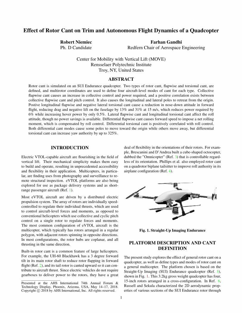
Fig. 1. Straight-Up Imaging Endurance
PLATFORM DESCRIPTION AND CANTDEFINITION
The present study explores the effect of general rotor cant on aquadcopter, as well as define types and modes of rotor cant ona general multicopter. The platform chosen is based on theStraight-Up Imaging (SUI) Endurance quadcopter (Ref. 5),shown in Fig. 1. This 3.2kg gross weight quadcopter has four,15-inch rotors arranged in a cross-configuration. In Ref. 6,Russell and Sekula characterized the 2D aerodynamic prop-erties of various sections of the SUI Endurance rotor through
1
-40 -20 0 20 40Angle of Attack (deg)
-0.05
0
0.05
0.1
F/q
(m
2)
LiftDrag
Fig. 2. Aerodynamic loads on the fuselage, normalized bydynamic pressure, versus angle of attack (positive nose-up)
Fig. 3. Cant Types
CFD on a laser-scan of the rotor. Fuselage forces, normalizedby dynamic pressure, are plotted in Fig. 2. This data wastaken from wind-tunnel experiments on the bare airframe ofthe SUI Endurance by Russell et al. in Ref 7.
Beginning from this platform, the rotors are canted about twoaxes (Fig. 3), one extending radially from the geometric cen-ter of the aircraft, representing a torsional cant (χ), and an axisorthogonal to that and the rotational axis of the uncanted ro-tor. Rotation about this axis is denoted as ”flapwise cant” (γ).The sign convention used in this study has positive γ result-ing in the thrust pointing toward the aircraft centerbody, whilepositive χ results in the thrust vector undergoing a counter-clockwise rotation as viewed down the boom axis toward thecenterbody.
Instead of defining the cant angles for each rotor individually,multi-rotor coordinates will be used to define modes at the air-craft level. Multi-rotor coordinates have previously been de-fined by the authors in their study of power-optimal controlsof a multicopter (Ref. 8). The four modes of flapwise cant areillustrated in Fig. 4, and the redirection of thrust, as viewedfrom the top of the aircraft is illustrated in Fig. 5. Positivecollective flapwise cant (γ0, Fig. 4(a)) applies positive γ to allrotors, vectoring thrust inboard (Fig. 5(a)), with no net forcesexcept a decrease in vertical thrust. Lateral flapwise cant (γ1s,Fig. 4(b)) cants rotors on the right side of the aircraft posi-tively, and rotors on the left side negatively, reorienting over-all thrust leftward (Fig. 5(b)). Positive longitudinal flapwisecant (γ1c, Fig. 4(c)) cants rear rotors positively and front ro-tors negatively, reorienting thrust forward (Fig. 5(c)). Finally,differential flapwise cant (γd , Fig. 4(d)) alternates betweennegative and positive cant, starting with the front-right rotor.This results in counter-clockwise-spinning rotors (pictured inblue in Fig. 4) having negative cant, and clockwise-spinningrotors (pictured in red in Fig. 4) having positive cant. Thrustis redirected as shown in Fig. 5(d), and like collective flap-wise cant, results no net forces, except a reduction in verticalthrust.
The four modes of torsional cant are plotted in Fig. 6. Col-
lective torsional cant (χ0, Fig. 6(a), applies equally to allfour rotors. This causes all four rotors’ thrusts to producea large nose-right moment about the aircraft C.G. (Fig. 7(a)),which the rotor torque is usually unable to compensate, mean-ing no trim solutions exist. Therefore, this cant mode is notused in this study. Lateral torsional cant (χ1s, Fig. 6(b)applies positive χ to rotors on the right, and negative χ torotors on the left, resulting in a net aftward vectoring ofthrust. Longtitudinal torsional cant (χ1c, Fig. 6(c) producesa net leftward thrust by canting forward rotors negativelyand rear rotors positively. Differential torsional cant (χd ,Fig. 6(d)) alternates positive and negative torsional cant, sothat counter-clockwise-spinning rotors are canted negatively,while clockwise-spinning rotors are canted positively. If theazimuthal angle, Ψ, is defined as zero at the aft of the aircraftand increasing counter-clockwise (as in Fig. 8), then a trans-formation from multi-rotor coordinates to individual-rotor co-ordinates is defined by Eq. 1, which can be used to determinethe individual cant angles from the aircraft-level modes.
Fig. 7. In-plane component of thrust with each mode of torsional cant (Resultant in blue)
3
Fig. 8. Top view of quadrotor
As a fixed-pitch, variable RPM vehicle, the quadcopter is con-trolled by regulating the speed of the individual rotors. Often,these speeds are expressed in individual rotor coordinates. Inthis study, the controls are represented in multi-rotor coordi-nates, as in (Ref. 8). The multirotor controls of a quadcopterare illustrated in Fig. 9. The collective mode (Ω0, Fig. 9(a))represents the average speed of the four rotors; changing itsvalue increases or decreases the speed of all four rotors si-multaneously. On a cant-free quadcopter in hover, this regu-lates vertical thrust without generating any other forces or mo-ments. Roll control is given by applying a differential RPMbetween the left and right rotors (ΩR, Fig. 9(b)). Similarly,pitch and yaw control are provided by applying a differen-tial RPM between the front/aft rotors (ΩP, Fig. 9(c)) and thecounter-clockwise- and clockwise-spinning rotors (ΩY , Fig.9(d)). Individual rotor speeds can be determined through acoordinate transformation identical to Eq. 1.
MODELING
To assess the effect of rotor cant on aerodynamic performance,a dynamic simulation is implemented. Accelerations on theaircraft are calcualted via sum of forces and moments aboutthe aircraft center of gravity, assumed to lie below the rotorplane at the geometric center of the aircraft. The forces in-clude gravity, rotor loads, and fuselage drag. Rotor forcesand moments are calculated via blade element theory, usinga 10-state Peters-He finite-state dynamic wake model on eachrotor. It was previously shown that this number of states cap-tures the average forces and moments of a multicopter rotor atthis scale ( (Ref. 9)). Rotor-rotor and rotor-fuselage interfer-ence is neglected in this study.
Vectors in this study are defined with respect to one of sev-eral reference frames. The first is an inertial reference frame,
attached to an arbitrary fixed point in space. The axes are de-fined with a North-East-Down convention. The second ref-erence frame is a body-attached frame, also with a North-East-Down convention, with North and East being definedas Ψ = 180 and Ψ = 90 as shown in Fig. 8, respectively.Rotation from the inertial to the body reference frame is de-fined using a 3-2-1 Euler rotation (Eq. 2, where c = cos(),s = sin()), while φ , θ , and ψ are the roll, pitch, and yawattitudes, respectively.
Rb/i = Rφ Rθ Rψ
=
1 0 00 cφ sφ
0 −sφ cφ
cθ 0 −sθ
0 1 0sθ 0 cθ
cψ sψ 0−sψ cψ 0
0 0 1
=
cθ cψ cθ sψ −sθ
sφ sθ cψ − cφ sψ sφ sθ sψ + cφ cψ sφ cθ
cφ sθ cψ + sφ sψ cφ sθ sψ − sφ cψ cφ cθ
(2)
An additional reference frame is defined at the hub of eachrotor, with its z-axis aligned with the axis of rotation. Thetransformation between the body frame and the hub frameis achieved using a unit quaternion defined by a unit vectorabout which rotation occurs and the magnitude of that rota-tion. For torsional cant, the unit vector ~xχ (defined in thebody-reference frame) and quaternion qχ are defined by Eq. 3,and by Eq. 4 for flapwise cant. The rotation matrix is then de-fined by Eq. 5, where qr, qi, q j, qk represent the first throughfourth entries of either qχ or qγ . Finally, the rotations are com-pounded (flapwise, then torsion-wise), resulting in a rotationmatrix from the body frame to the hub frame.
In order to satisfy the equilibrium equations defined by thesum of forces and moments about the C.G. in a body-attachedreference frame, a trim procedure is established, using the four
4
(a) Collective Control (Ω0) (b) Roll Control (ΩR) (c) Pitch Control (ΩP) (d) Yaw Control (ΩY )
Fig. 9. Multirotor controls for a quadcopter
0 5 10 15Forward Speed (m/s)
2200
2250
2300
2350
2400
Col
lect
ive
Con
trol
(R
PM
)
(a) Collective Control
0 5 10 15Forward Speed (m/s)
-15
-10
-5
0
Pitc
h A
ttitu
de (
deg)
(b) Pitch Attitude
0 5 10 15Forward Speed (m/s)
0
20
40
60
80
Pitc
h C
ontr
ol (
RP
M)
(c) Pitch Control
Fig. 10. Trim Controls for baseline quadcopter
rotor speeds (defined using multi-rotor coordinates), and theroll and pitch attitudes of the aircraft. Solutions are foundusing the Newton-Raphson method, with the Jacobian numer-ically estimated. The (time-averaged) rotor inflow states aresolved simultaneously with the trim states.
In order to estimate the flight dynamics of the quadcopter, themodel is numerically linearized from an equilibrium condi-tion, resulting in a model of the form of Eq. 6. The statevector x ∈ R52 contains the position (3), attitude (3), velocity(3), angular rates (3), and inflow states (4×10=40). The con-trol vector u ∈ R4 contains the control inputs. A ∈ R52×52 isthe linearized plant model, containing the stability derivatives,and B ∈ R52×4 contains control sensitivities. Because the in-flow dynamics occur on a much smaller time scale (associatedpoles far in the left-half plane), the technique of static conden-sation can be used to reduce the size of the system to 12×12.This reduction does not affect the poles associated with rigidbody motion, as shown in (Ref. 10).
x = Ax+Bu (6)
TRIM RESULTS
The required trim controls for a cross-type quadcopter with-out any rotor cant is presented in Fig. 10. In hover, onlythrust needs to be generated, so all four rotors spin at the
same speed. At low-speeds, the collective control (Fig. 10(a))reduces slightly, reflecting the increased efficiency of the ro-tors at moderate speed, reaching a minimum at 9 m/s. Due toincreasing thrust requirements at speeds beyond this, the re-quired collective RPM increases. In order to overcome dragin forward flight, the aircraft needs to pitch nose-down in or-der to vector its thrust forward, becoming increasingly neg-ative as speed increases (Fig. 10(b)). In order to maintainthis nose-down attitude and overcome the hub pitching mo-ment on each rotor (detailed in (Ref. 9)), the rear rotors needto generate more thrust, i.e. spin faster, which is reflected inFig. 10(c). At the rotor level, the magnitude of the side force,rolling moment, and torque are dependent primarily on the ro-tor speed, while the direction is dictated by the spin directionof the rotor (e.g. a counter-clockwise-spinning rotor producesa roll-left moment while a clockwise-spinning rotor producesa roll-right moment). By the definition of the multirotor con-trols in Fig. 9, when using only collective and pitch controls,the two front rotors (and the two rear rotors) spin at the samespeed, in opposite directions. Therefore, at the aircraft level,the lateral forces and moments cancel out.
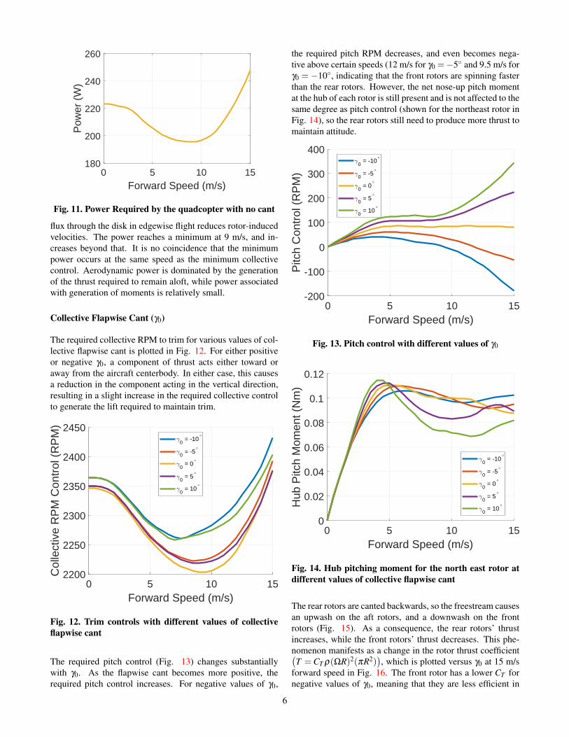
The aerodynamic power (ignoring all inefficiencies associatedwith the motor and other electronics, as well as interactionalaerodynamic effects) required by the quadcopter is shown inFig. 11. Beginning from a local maximum in hover, the powerrequired to fly reduces in forward flight, as the extra mass
5
0 5 10 15Forward Speed (m/s)
180
200
220
240
260
Pow
er (
W)
Fig. 11. Power Required by the quadcopter with no cant
flux through the disk in edgewise flight reduces rotor-inducedvelocities. The power reaches a minimum at 9 m/s, and in-creases beyond that. It is no coincidence that the minimumpower occurs at the same speed as the minimum collectivecontrol. Aerodynamic power is dominated by the generationof the thrust required to remain aloft, while power associatedwith generation of moments is relatively small.
Collective Flapwise Cant (γ0)
The required collective RPM to trim for various values of col-lective flapwise cant is plotted in Fig. 12. For either positiveor negative γ0, a component of thrust acts either toward oraway from the aircraft centerbody. In either case, this causesa reduction in the component acting in the vertical direction,resulting in a slight increase in the required collective controlto generate the lift required to maintain trim.
0 5 10 15Forward Speed (m/s)
2200
2250
2300
2350
2400
2450
Col
lect
ive
RP
M C
ontr
ol (
RP
M)
0 = -10°
0 = -5°
0 = 0°
0 = 5°
0 = 10°
Fig. 12. Trim controls with different values of collectiveflapwise cant
The required pitch control (Fig. 13) changes substantiallywith γ0. As the flapwise cant becomes more positive, therequired pitch control increases. For negative values of γ0,
the required pitch RPM decreases, and even becomes nega-tive above certain speeds (12 m/s for γ0 =−5 and 9.5 m/s forγ0 =−10, indicating that the front rotors are spinning fasterthan the rear rotors. However, the net nose-up pitch momentat the hub of each rotor is still present and is not affected to thesame degree as pitch control (shown for the northeast rotor inFig. 14), so the rear rotors still need to produce more thrust tomaintain attitude.
0 5 10 15Forward Speed (m/s)
-200
-100
0
100
200
300
400
Pitc
h C
ontr
ol (
RP
M)
0 = -10°
0 = -5°
0 = 0°
0 = 5°
0 = 10°
Fig. 13. Pitch control with different values of γ0
0 5 10 15Forward Speed (m/s)
0
0.02
0.04
0.06
0.08
0.1
0.12
Hub
Pitc
h M
omen
t (N
m)
0 = -10°
0 = -5°
0 = 0°
0 = 5°
0 = 10°
Fig. 14. Hub pitching moment for the north east rotor atdifferent values of collective flapwise cant
The rear rotors are canted backwards, so the freestream causesan upwash on the aft rotors, and a downwash on the frontrotors (Fig. 15). As a consequence, the rear rotors’ thrustincreases, while the front rotors’ thrust decreases. This phe-nomenon manifests as a change in the rotor thrust coefficient(T = CT ρ(ΩR)2(πR2)
), which is plotted versus γ0 at 15 m/s
forward speed in Fig. 16. The front rotor has a lower CT fornegative values of γ0, meaning that they are less efficient in
6
producing thrust, and that although they are spinning faster,they are producing less thrust than the rear rotors. The othertrim controls are not significantly affected.
Fig. 15. Forward speed causes downwash on the front ro-tors, and upwash on the rear rotors (drawn at zero pitchattitude for clarity)
-10 -5 0 5 10
0 (deg)
7
8
9
10
11
12
CT
10-3
Front RotorRear Rotor
Fig. 16. Front and rear rotor thrust coefficient for thequadcopter with flapwise cant at 15 m/s
The power required by the quadcopter is dominated by themean thrust generated, and thus, collective control. Relativeto the uncanted case,±5 and±10 of γ0 costs 0.5% and 2.1%in hover power, shown in Fig. 17, but the extra power requiredincreases with forward speed, up to 3.5-4% for γ0 = ±5 or11% for γ0 =±10 at 10.5 m/s. The decrease in relative powerat high speed is mostly due to the sharp increase in powerrequired at high speeds.
Longitudinal Flapwise Cant γ1c
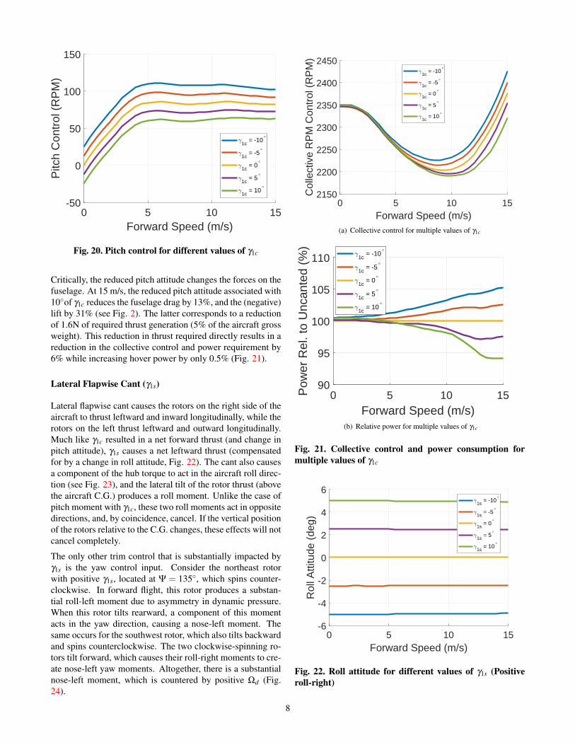
Application of longitudinal flapwise cant (Fig. 4(c)) causesthe two front rotors to redirect their thrust forward and out-ward laterally, and the rear rotors redirect their thrust forwardand inward laterally. This causes a net forward vectoring ofthrust, which requires a more-nose up (or less nose-down) at-titude, relative to the uncanted system (Fig. 18) by γ1c/2.Figure 19 illustrates the component of rotor hub torque thatacts in the body frame XY-plane. The torques balance aboutthe roll axis, but compound about the pitch axis, resulting ina nose-down pitching moment. Combined with the forwardreorientation of thrust, acting above the aircraft C.G., this re-duces the required pitch control input (Fig. 20)
Fig. 17. Relative power costs for different values of γ0
0 5 10 15Forward Speed (m/s)
-20
-15
-10
-5
0
5
10
Pitc
h A
ttitu
de (
deg)
1c = -10°
1c = -5°
1c = 0°
1c = 5°
1c = 10°
Fig. 18. Pitch attitude for different values of γ1c (Positivenose-up)
Fig. 19. Vector representation of in-plane component ofhub torque (Resultant in blue)
7
0 5 10 15Forward Speed (m/s)
-50
0
50
100
150P
itch
Con
trol
(R
PM
)
1c = -10°
1c = -5°
1c = 0°
1c = 5°
1c = 10°
Fig. 20. Pitch control for different values of γ1c
Critically, the reduced pitch attitude changes the forces on thefuselage. At 15 m/s, the reduced pitch attitude associated with10of γ1c reduces the fuselage drag by 13%, and the (negative)lift by 31% (see Fig. 2). The latter corresponds to a reductionof 1.6N of required thrust generation (5% of the aircraft grossweight). This reduction in thrust required directly results in areduction in the collective control and power requirement by6% while increasing hover power by only 0.5% (Fig. 21).
Lateral Flapwise Cant (γ1s)
Lateral flapwise cant causes the rotors on the right side of theaircraft to thrust leftward and inward longitudinally, while therotors on the left thrust leftward and outward longitudinally.Much like γ1c resulted in a net forward thrust (and change inpitch attitude), γ1s causes a net leftward thrust (compensatedfor by a change in roll attitude, Fig. 22). The cant also causesa component of the hub torque to act in the aircraft roll direc-tion (see Fig. 23), and the lateral tilt of the rotor thrust (abovethe aircraft C.G.) produces a roll moment. Unlike the case ofpitch moment with γ1c, these two roll moments act in oppositedirections, and, by coincidence, cancel. If the vertical positionof the rotors relative to the C.G. changes, these effects will notcancel completely.
The only other trim control that is substantially impacted byγ1s is the yaw control input. Consider the northeast rotorwith positive γ1s, located at Ψ = 135, which spins counter-clockwise. In forward flight, this rotor produces a substan-tial roll-left moment due to asymmetry in dynamic pressure.When this rotor tilts rearward, a component of this momentacts in the yaw direction, causing a nose-left moment. Thesame occurs for the southwest rotor, which also tilts backwardand spins counterclockwise. The two clockwise-spinning ro-tors tilt forward, which causes their roll-right moments to cre-ate nose-left yaw moments. Altogether, there is a substantialnose-left moment, which is countered by positive Ωd (Fig.24).
0 5 10 15Forward Speed (m/s)
2150
2200
2250
2300
2350
2400
2450
Col
lect
ive
RP
M C
ontr
ol (
RP
M)
1c = -10°
1c = -5°
1c = 0°
1c = 5°
1c = 10°
(a) Collective control for multiple values of γ1c
0 5 10 15Forward Speed (m/s)
90
95
100
105
110
Pow
er R
el. t
o U
ncan
ted
(%)
1c = -10°
1c = -5°
1c = 0°
1c = 5°
1c = 10°
(b) Relative power for multiple values of γ1c
Fig. 21. Collective control and power consumption formultiple values of γ1c
0 5 10 15Forward Speed (m/s)
-6
-4
-2
0
2
4
6
Rol
l Atti
tude
(de
g)
1s = -10°
1s = -5°
1s = 0°
1s = 5°
1s = 10°
Fig. 22. Roll attitude for different values of γ1s (Positiveroll-right)
8
Fig. 23. Vector representation of in-plane component ofhub torque (Resultant in blue)
0 5 10 15Forward Speed (m/s)
-300
-200
-100
0
100
200
300
Yaw
Con
trol
(R
PM
)
1s = -10°
1s = -5°
1s = 0°
1s = 5°
1s = 10°
Fig. 24. Yaw control for different values of γ1s
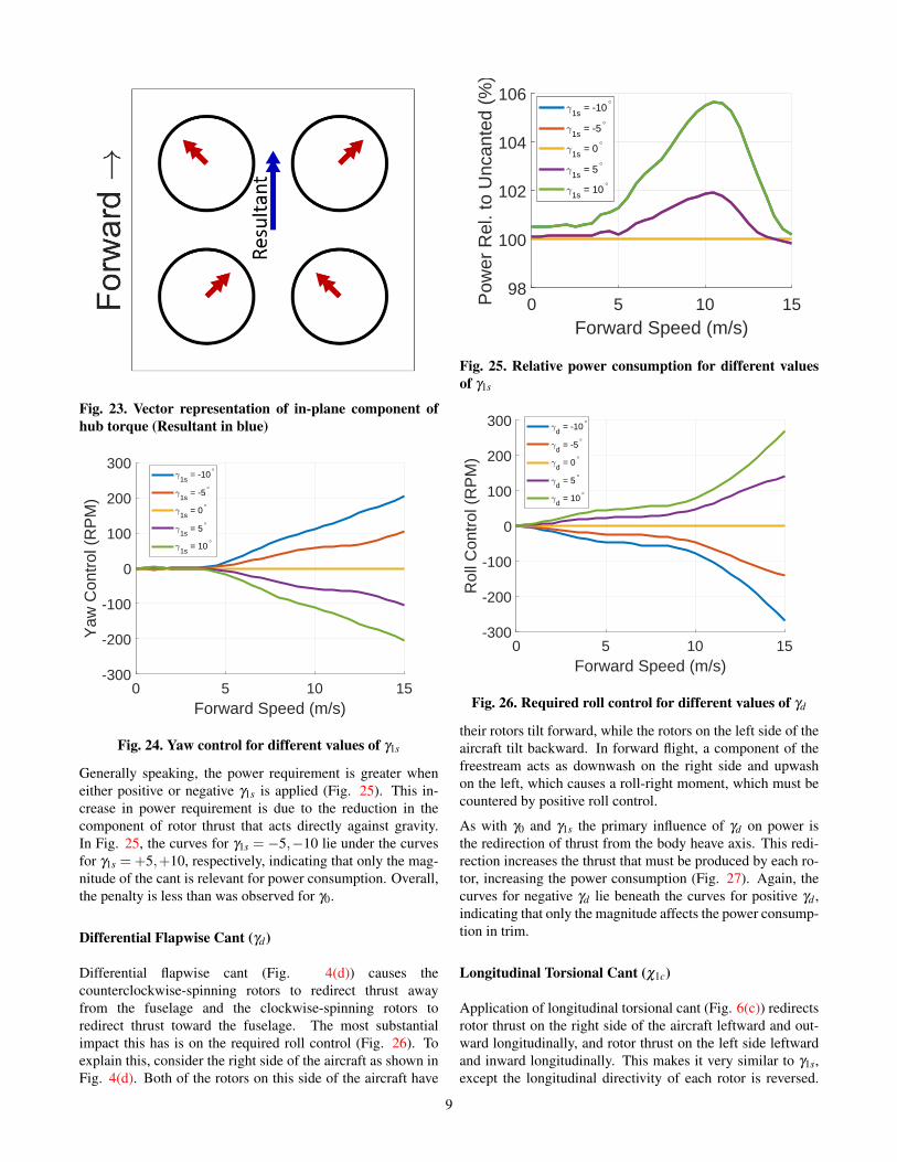
Generally speaking, the power requirement is greater wheneither positive or negative γ1s is applied (Fig. 25). This in-crease in power requirement is due to the reduction in thecomponent of rotor thrust that acts directly against gravity.In Fig. 25, the curves for γ1s = −5,−10 lie under the curvesfor γ1s =+5,+10, respectively, indicating that only the mag-nitude of the cant is relevant for power consumption. Overall,the penalty is less than was observed for γ0.
Differential Flapwise Cant (γd)
Differential flapwise cant (Fig. 4(d)) causes thecounterclockwise-spinning rotors to redirect thrust awayfrom the fuselage and the clockwise-spinning rotors toredirect thrust toward the fuselage. The most substantialimpact this has is on the required roll control (Fig. 26). Toexplain this, consider the right side of the aircraft as shown inFig. 4(d). Both of the rotors on this side of the aircraft have
0 5 10 15Forward Speed (m/s)
98
100
102
104
106
Pow
er R
el. t
o U
ncan
ted
(%)
1s = -10°
1s = -5°
1s = 0°
1s = 5°
1s = 10°
Fig. 25. Relative power consumption for different valuesof γ1s
0 5 10 15Forward Speed (m/s)
-300
-200
-100
0
100
200
300
Rol
l Con
trol
(R
PM
)
d = -10°
d = -5°
d = 0°
d = 5°
d = 10°
Fig. 26. Required roll control for different values of γd
their rotors tilt forward, while the rotors on the left side of theaircraft tilt backward. In forward flight, a component of thefreestream acts as downwash on the right side and upwashon the left, which causes a roll-right moment, which must becountered by positive roll control.
As with γ0 and γ1s the primary influence of γd on power isthe redirection of thrust from the body heave axis. This redi-rection increases the thrust that must be produced by each ro-tor, increasing the power consumption (Fig. 27). Again, thecurves for negative γd lie beneath the curves for positive γd ,indicating that only the magnitude affects the power consump-tion in trim.
Longitudinal Torsional Cant (χ1c)
Application of longitudinal torsional cant (Fig. 6(c)) redirectsrotor thrust on the right side of the aircraft leftward and out-ward longitudinally, and rotor thrust on the left side leftwardand inward longitudinally. This makes it very similar to γ1s,except the longitudinal directivity of each rotor is reversed.
9
0 5 10 15Forward Speed (m/s)
100
105
110
115P
ower
Rel
. to
Unc
ante
d (%
)d = -10°
d = -5°
d = 0°
d = 5°
d = 10°
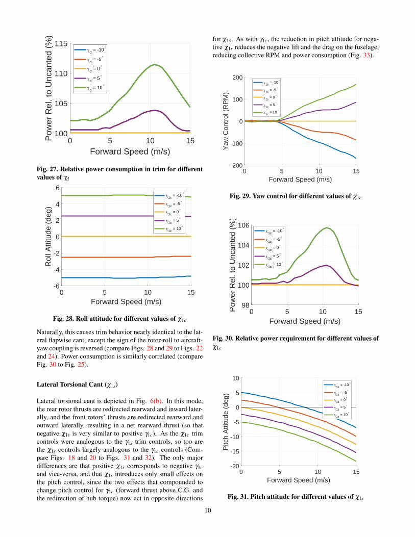
Fig. 27. Relative power consumption in trim for differentvalues of γd
0 5 10 15Forward Speed (m/s)
-6
-4
-2
0
2
4
6
Rol
l Atti
tude
(de
g)
1c = -10°
1c = -5°
1c = 0°
1c = 5°
1c = 10°
Fig. 28. Roll attitude for different values of χ1c
Naturally, this causes trim behavior nearly identical to the lat-eral flapwise cant, except the sign of the rotor-roll to aircraft-yaw coupling is reversed (compare Figs. 28 and 29 to Figs. 22and 24). Power consumption is similarly correlated (compareFig. 30 to Fig. 25).
Lateral Torsional Cant (χ1s)
Lateral torsional cant is depicted in Fig. 6(b). In this mode,the rear rotor thrusts are redirected rearward and inward later-ally, and the front rotors’ thrusts are redirected rearward andoutward laterally, resulting in a net rearward thrust (so thatnegative χ1s is very similar to positive γ1c). As the χ1c trimcontrols were analogous to the γ1s trim controls, so too arethe χ1s controls largely analogous to the γ1c controls (Com-pare Figs. 18 and 20 to Figs. 31 and 32). The only majordifferences are that positive χ1s corresponds to negative γ1cand vice-versa, and that χ1s introduces only small effects onthe pitch control, since the two effects that compounded tochange pitch control for γ1c (forward thrust above C.G. andthe redirection of hub torque) now act in opposite directions
for χ1s. As with γ1c, the reduction in pitch attitude for nega-tive χ1s reduces the negative lift and the drag on the fuselage,reducing collective RPM and power consumption (Fig. 33).
0 5 10 15Forward Speed (m/s)
-200
-100
0
100
200
Yaw
Con
trol
(R
PM
)
1c = -10°
1c = -5°
1c = 0°
1c = 5°
1c = 10°
Fig. 29. Yaw control for different values of χ1c
0 5 10 15Forward Speed (m/s)
98
100
102
104
106P
ower
Rel
. to
Unc
ante
d (%
)1c
= -10°
1c = -5°
1c = 0°
1c = 5°
1c = 10°
Fig. 30. Relative power requirement for different values ofχ1c
0 5 10 15Forward Speed (m/s)
-20
-15
-10
-5
0
5
10
Pitc
h A
ttitu
de (
deg)
1s = -10°
1s = -5°
1s = 0°
1s = 5°
1s = 10°
Fig. 31. Pitch attitude for different values of χ1s
10
0 5 10 15Forward Speed (m/s)
-20
0
20
40
60
80
100P
itch
Con
trol
(R
PM
)
1s = -10°
1s = -5°
1s = 0°
1s = 5°
1s = 10°
Fig. 32. Pitch controls for different values of χ1s
0 5 10 15Forward Speed (m/s)
2150
2200
2250
2300
2350
2400
2450
Col
lect
ive
RP
M C
ontr
ol (
RP
M)
1s = -10°
1s = -5°
1s = 0°
1s = 5°
1s = 10°
(a) Collective control
0 5 10 15Forward Speed (m/s)
90
95
100
105
110
Pow
er R
el. t
o U
ncan
ted
(%)
1s = -10°
1s = -5°
1s = 0°
1s = 5°
1s = 10°
(b) Relative power
Fig. 33. Collective control and power consumption formultiple values of χ1s
Differential Torsional Cant (χd)
Differential torsional cant (Fig. 6(d)) directs the thrust fromthe front two rotors forward and inward laterally, and the reartwo rotors rearward and inward laterally. If positive χd is ap-plied, a component of the freestream velocity acts as upwashon the rear rotors and downwash on the front rotors, whichcauses a nose-down moment, reducing the required pitch con-trol, similar to γ0 (Compare Figs. 13 and 34). Aside from that,the collective control and power consumption are identical tothe γ0 case (except positive χd corresponds to negative γ0).
0 5 10 15Forward Speed (m/s)
-200
-100
0
100
200
300
400
Pitc
h C
ontr
ol (
RP
M)
d = -10°
d = -5°
d = 0°
d = 5°
d = 10°
Fig. 34. Pitch control for different values of χd
LINEAR DYNAMICS
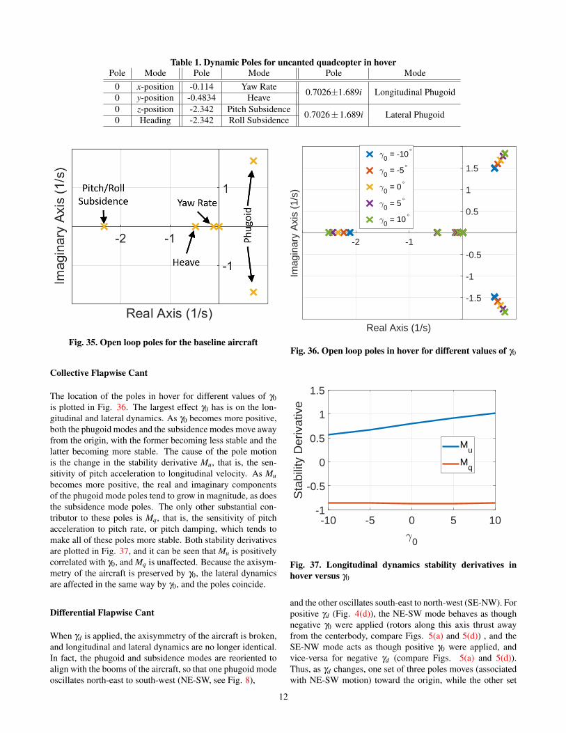
After numerically linearizing the quadcopter model about anequilibrium condition, the flight dynamics are described byEq. 6. As the reduced system is a 12-state model, thereare twelve open-loop poles associated with the eigenvaluesof A, plotted for the aircraft with zero cant in hover in Fig.35. The eigenvectors associated with these eigenvalues rep-resent the dynamic modes of the quadcopter. There are fourpoles located at the origin, corresponding to the position statesand the heading. There are two poles located at λ = −2.342corresponding to the pitch and roll subsidence modes, onepole at λ = −0.4834 corresponding to the heave mode, onepole at λ =−0.114 corresponding to the yaw rate mode, andtwo pairs of complex conjugate poles at λ = 0.7026±1.689icorresponding to the longitudinal and lateral phugoid modes.These poles are also tabulated in Table 1. Only collective anddifferential flapwise cant, and differential torsional cant, haveany significant impact on the locations of these poles in hover.
11
Table 1. Dynamic Poles for uncanted quadcopter in hoverPole Mode Pole Mode Pole Mode
Fig. 35. Open loop poles for the baseline aircraft
Collective Flapwise Cant
The location of the poles in hover for different values of γ0is plotted in Fig. 36. The largest effect γ0 has is on the lon-gitudinal and lateral dynamics. As γ0 becomes more positive,both the phugoid modes and the subsidence modes move awayfrom the origin, with the former becoming less stable and thelatter becoming more stable. The cause of the pole motionis the change in the stability derivative Mu, that is, the sen-sitivity of pitch acceleration to longitudinal velocity. As Mubecomes more positive, the real and imaginary componentsof the phugoid mode poles tend to grow in magnitude, as doesthe subsidence mode poles. The only other substantial con-tributor to these poles is Mq, that is, the sensitivity of pitchacceleration to pitch rate, or pitch damping, which tends tomake all of these poles more stable. Both stability derivativesare plotted in Fig. 37, and it can be seen that Mu is positivelycorrelated with γ0, and Mq is unaffected. Because the axisym-metry of the aircraft is preserved by γ0, the lateral dynamicsare affected in the same way by γ0, and the poles coincide.
Differential Flapwise Cant
When γd is applied, the axisymmetry of the aircraft is broken,and longitudinal and lateral dynamics are no longer identical.In fact, the phugoid and subsidence modes are reoriented toalign with the booms of the aircraft, so that one phugoid modeoscillates north-east to south-west (NE-SW, see Fig. 8),
-2 -1
Real Axis (1/s)
-1.5
-1
-0.5
0.5
1
1.5
Imag
inar
y A
xis
(1/s
)
0 = -10°
0 = -5°
0 = 0°
0 = 5°
0 = 10°
Fig. 36. Open loop poles in hover for different values of γ0
-10 -5 0 5 10
0
-1
-0.5
0
0.5
1
1.5
Sta
bilit
y D
eriv
ativ
e
Mu
Mq
Fig. 37. Longitudinal dynamics stability derivatives inhover versus γ0
and the other oscillates south-east to north-west (SE-NW). Forpositive γd (Fig. 4(d)), the NE-SW mode behaves as thoughnegative γ0 were applied (rotors along this axis thrust awayfrom the centerbody, compare Figs. 5(a) and 5(d)) , and theSE-NW mode acts as though positive γ0 were applied, andvice-versa for negative γd (compare Figs. 5(a) and 5(d)).Thus, as γd changes, one set of three poles moves (associatedwith NE-SW motion) toward the origin, while the other set
12
-2 -1
Real Axis (1/s)
-1.5
-1
-0.5
0.5
1
1.5
Imag
inar
y A
xis
(1/s
)d = -10°
d = -5°
d = 0°
d = 5°
d = 10°
Fig. 38. Open loop poles in hover for different values of γd
of three poles (associated with SE-NW motion) moves away(Fig. 38).
Differential Torsional Cant
As when γd was applied, the axisymmetry of the aircraft isbroken when χd is applied, so longitudinal and lateral dynam-ics are no longer identical. However, χd tends to align thephugoid modes between the booms of the quadcopter, whichhappen to align with the flight axes. The open loop poles areplotted in Fig. 39. For positive χd , the upwash on the rearrotors and downwash on the front rotors in forward flight re-duces Mu, causing the longitudinal poles to move toward theorigin. Considering the lateral axis, a rightward aircraft ve-locity causes upwash through the right rotors, and downwashthrough the left, causing a roll-left moment, enhancing thesensitivity of roll acceleration to lateral velocity, causing thelateral poles to move away from the origin. Negative χd doesthe opposite, making the longitudinal phugoid mode less sta-ble, and the lateral phugoid mode more stable.
Unique among the eight cant modes defined in Figs. 4 and6, χd also has a significant effect on the control sensitivitymatrix, B, in Eq. 6, specifically on the relationship betweenΩd (Fig. 9(d)) and yaw acceleration. In the absence of cant,increasing the speed of the counter-clockwise-spinning rotorswhile reducing the speed of the clockwise-spinning rotors pro-duces a net nose-right reaction torque on the aircraft. Whenpositive χd is applied, a component of rotor thrust also servesto produce a yaw moment, with the counter-clockwise rotorthrust producing a nose-left moment, and the clockwise ro-tor thrust produces a nose-right moment. When Ωd is ap-plied, the counter-clockwise-rotor thrust is increased, and theclockwise-rotor thrust is decreased, producing a net nose-leftmoment, opposite that induced by the hub reaction torque. Fornegative χd , these two effects act in the same direction. Thesensitivity of yaw acceleration to Ωd is plotted in Fig. 40.With χd = −10, the sensitivity of yaw acceleration to Ωd is
-2 -1
Real Axis (1/s)
-1.5
-1
-0.5
0.5
1
1.5
Imag
inar
y A
xis
(1/s
)
d = -10°
d = -5°
d = 0°
d = 5°
d = 10°
Fig. 39. Open loop poles in hover for different values of χd
-10 -5 0 5 10
d
-0.04
-0.02
0
0.02
0.04
0.06
0.08
Yaw
Sen
sitiv
ity (
1/s)
Fig. 40. Yaw acceleration-Ωd in hover sensitivity for dif-ferent values of χd
increased by 325%, for a maximum of 12% increase in power.A 162% increase in sensitivity can be obtained with χd =−5
for a maximum of 4.2% increase in power.
CONCLUSIONS
An SUI Endurance was modified by applying various types ofcant to its rotors. Four aircraft-level modes were defined forcant for two different types of rotor cant, and their effects onpredicted trim controls and linear flight dynamics estimated.
Application of collective flapwise cant resulted in a generalincrease in required collective RPM control, and a positivecorrelation between γ0 and pitch control was found. This wasdue to the freestream acting as downwash or upwash, depend-ing on the orientation of the rotor. Power was increased by0.5% (γ0 = ±5 in hover) to 11% (γ0 = ±10 at 10.5 m/s).Similar effects were found for χd , except with a negative cor-relation between χd and pitch control. Longitudinal flapwise
13
cant and lateral torsional cant both result in rotors canting for-ward, and so they have similar effects, most importantly, apositive (negative) correlation between γ1c (χ1s) and pitch at-titude. In general, if k of γ1c (or −k of χ1s) is applied, thepitch attitude in trim increases (becomes more nose-up) byk/2. When the pitch attitude, negative in forward flight, isreduced (so that the aircraft flies more nose-level), the nega-tive lift and the drag of the fuselage is similarly reduced, by31% and 13% at 15 m/s for γ1c = 10 (or χ1s =−10), reduc-ing overall aircraft power at 15 m/s by 6%, with only a 0.5%increase in hover power. Lateral flapwise cant (and longitudi-nal torsional cant) have similar effects on the lateral direction,though no power savings is available through changing the rollattitude. Additionally, because a component of the hub rollmoment applies in the yaw direction, a negative correlationbetween γ1s and yaw control is found. Similarly, χ1c affectsyaw control, but in the opposite direction. Finally, γd caused achange in the roll control in trim, due to a relative downwashon right-side rotors, and an upwash on left-side rotors.
Application of positive collective flapwise cant causes thepoles associated with the longitudinal and lateral dynamicsto move away from the origin. This pole motion is causedby a change in the sensitivity of pitch acceleration to forwardspeed, caused by the same relative upwash/downwash thatchanges the pitch control. Differential flapwise cant breaksthe symmetry of the aircraft, so the longitudinal and lateralpoles are no longer coincident. Additionally, the phugoid andsubsidence modes become oriented along the booms, ratherthan on the flight axes. For positive or negative γd , one set ofmodes moves away from the origin, while the other set movestoward the origin. χd also breaks the symmetry of the air-craft, and the longitudinal/lateral modes are oriented betweenthe booms (due to the layout of the rotors, they coincide withthe flight axes). Positive χd causes the longitudinal modes tomove toward from the origin, making the phugoid modes lessunstable. −10 (−5) of χd causes a 325% (162%) increase inthe yaw authority of the quadcopter, by redirecting the thrustof all four rotors so that the rotor thrust differential caused byyaw control adds to the hub counter-torque, at a maximum of12% (4.2%) increase in power.
ACKNOWLEDGMENTS
The authors acknowledge the Department of Defense and theAmerican Society for Engineering Education for supportingRobert Niemiec through the National Defense Science andEngineering Graudate (NDSEG) Fellowship.
REFERENCES1Giannini, F., Kaufman, A., and Kearney, M., “Configu-
ration Development and Subscale Flight Testing of an Ur-ban Mobility eVTOL,” Proceedings of the AHS InternationalTechnical Meeting on Aeromechanics Design for Transforma-tive Vertical Lift, San Francisco, CA, Jan. 16-18, 2018, 2018.
2Hilbert, K., “A Mathematical Model of the UH-60 Heli-copter,” Technical Memorandum 85890, NASA, 1984.
3Brescanini, D. and D’Andrea, R., “Design, Modeling, andControl of an Omni-Directional Aerial Vehicle,” Proceedingsof the 2016 International Conference on Robotics and Au-tomation, Stockholm, Sweden, 2016.
4Phillips, B., Hrisikeshavan, V., Yeo, D., and Chopra, I.,“Experimental Evaluation of a Quadrotor Biplane with Vari-able Pitch Rotors,” 73rd Annual Forum of the American He-licopter Society, Fort Worth, Texas, 2017.
5“Products — STRAIGHT UP IMAGING,”http://www.straightupimaging.com/products/.
6Russell, C. and Sekula, M., “Comprehensive AnalysisModeling of Small-Scale UAS Rotors,” 73rd Annual Forumof the American Helicopter Society International, Fort Worth,Texas, 2017.
7Russell, C., Jung, J., Willink, G., and Glasner, B., “WindTunnel and Hover Performance Test Results for MulticopterUAS Vehicles,” 72nd Annual Forum of the American Heli-copter Society International, West Palm Beach, Florida, 2016.
8Niemiec, R. and Gandhi, F., “Multi-rotor CoordinateTransforms for Orthogonal Primary and Redundant ControlModes for Regular Hexacopters and Octocopters,” 42nd Eu-ropean Rotorcraft Forum, Lille, France, 2016.
9Niemiec, R. and Gandhi, F., “Effect on Inflow Model onSimulated Aeromechanics of a Quadrotor Helicopter,” 72ndAnnual Forum of the American Helicopter Society Interna-tional, West Palm Beach, Florida, 2016.
10Niemiec, R. and Gandhi, F., “Multirotor Controls, Trim,and Autonomous Flight Dynamics of Plus- and Cross-Quadcopters,” Journal of Aircraft, 2017.