An Evaluation of the Motions of Competition Seesaws— The Effect of Design on Performance I. Martin Levy, MD+, Peter A. Torzilli, PhD+ and Monica Percival* From +The Center for the Scientific Advancement of the Sport of Canine Agility, Ardsley, New York And *Clean Run Productions, LLC, Chicopee, Massachusetts INTRODUCTION The seesaw is unlike any other obstacle on a dog agility course in that the performance on the obstacle depends on the performance of the obstacle. Variations in plank, fulcrum and base construction directly influence the motion characteristics of each seesaw design. In an effort to insure consistency of performance, the organizational bodies for the sport of dog agility have been quite specific about plank dimensions and pivot height. However, they have been less precise when defining a seesaw’s response to varying conditions of load. Because of this, a variety of seesaw solutions have been designed and constructed, each with its own set of performance characteristics. The rate of descent, support base movement, plank vibration and noise are all influenced by the design solution and the materials chosen to execute that design. Dogs perform the seesaw obstacle with a great deal of precision. Successful performance of the obstacle is judged with equal precision. It is therefore essential that seesaws perform in a predictable and measurable manner so that a competing dog can expect a specific response. The seesaw used for dog agility is the standard example of a class I lever. In this case, a lever sits on a central pivot (the fulcrum) and motion occurs as the lever rotates on that fulcrum. If the lever is loaded on one side and the induced rotation is abruptly halted, the lever and base experience significant forces. These forces result in a variety of observed seesaw responses including bending and catapulting of the plank and hopping and creeping of the base.
Transcript
An Evaluation of the Motions of Competition Seesaws— The Effect of Design on Performance
I. Martin Levy, MD+, Peter A. Torzilli, PhD+ and Monica Percival*
From +The Center for the Scientific Advancement of the Sport of Canine Agility, Ardsley, New York
And *Clean Run Productions, LLC, Chicopee, Massachusetts
INTRODUCTION
The seesaw is unlike any other obstacle on a dog agility course in that the performance on
the obstacle depends on the performance of the obstacle. Variations in plank, fulcrum
and base construction directly influence the motion characteristics of each seesaw design.
In an effort to insure consistency of performance, the organizational bodies for the sport
of dog agility have been quite specific about plank dimensions and pivot height.
However, they have been less precise when defining a seesaw’s response to varying
conditions of load. Because of this, a variety of seesaw solutions have been designed and
constructed, each with its own set of performance characteristics. The rate of descent,
support base movement, plank vibration and noise are all influenced by the design
solution and the materials chosen to execute that design.
Dogs perform the seesaw obstacle with a great deal of precision. Successful performance
of the obstacle is judged with equal precision. It is therefore essential that seesaws
perform in a predictable and measurable manner so that a competing dog can expect a
specific response.
The seesaw used for dog agility is the standard example of a class I lever. In this case, a
lever sits on a central pivot (the fulcrum) and motion occurs as the lever rotates on that
fulcrum. If the lever is loaded on one side and the induced rotation is abruptly halted, the
lever and base experience significant forces. These forces result in a variety of observed
seesaw responses including bending and catapulting of the plank and hopping and
creeping of the base.
2
In an effort to understand the effect of design variations on the performance of a seesaw,
we evaluated three distinct designs. The purpose of the paper was to determine how each
design reacted to an applied load. In addition, we wanted to understand how varying the
load and the point of load application affected the response of the seesaw. Finally, we
wanted to determine how each seesaw responded to the abrupt cessation of plank
Ascending Arm - for this discussion, the portion of the plank or modified board that rises from a starting position on the ground when a force is applied to the descending arm. Board - A long, broad, flat piece of sawed wood; thin plank 1 Descending Arm - for this discussion, the raised end of the plank or modified board when it is in the starting position Fulcrum - the support or point of support upon which a lever turns 1 Modified Board - For this discussion, a board that has been strengthened by adding framing or structural supports of wood or metal Panel - a section or division of a surface, or one that constitutes a surface…a flat piece, usually rectangular forming the part of the surface of a wall, door, cabinet, etc., and usually raised, recessed, framed, etc.1 Pivot - a point, shaft, pin, etc. on which something turns.1
Plank - A long, broad, thick board 1
Seesaw - A plank balanced on a support in the middle 1 Teeter, Teeterboard, Teeter-Totter - Seesaw 1
1 Webster’s New World College Dictionary, fourth edition, 2002
Max 200 (Port Byron, New York), Action K-9 Sports Equipment (Sun City, California)
and Premier Agility Equipment (Surrey, England) seesaws, which are used regularly in
competition, were evaluated. They were selected because each had distinct design
elements.
The seesaws were assembled and the distance from the pivot point to the Agiliflex Plus
tile (Group Summit Flexible Products, Oregon) floor was measured. Once the base of the
seesaw was set on the surface and the modified board (m-board) was placed in its starting
4
position, the distance from the surface to the end of the descending arm of the m-board
was measured. The m-board of each seesaw was then separated from the base and the
base and board were weighed five times on a digital scale. An average weight for each
m-board and base was calculated.
Three sets of tests were performed. For the first set of tests, the seesaws were stabilized
by placing 100 pounds of crushed stone (in 50 pound bags) on the bases. Sandbags of
known weights (5, 10, 20, 30 and 50 pounds) were placed on the descending arm of the
seesaw, at known distances from the end of the descending arm. Tests were performed
with each differently weighted sandbag placed at 1, 2, 3 and 4 feet from the end of the m-
board. In addition, the balance point (BP) for a given sandbag was determined as the
point on the descending arm of the m-board where, when the sandbag was placed, the
board would hold a neutral position (both ends of the m-board level in the air). The
distance from the fulcrum to the balance point was measured and 12 inches were added to
it to calculate the BP+12 point. This point was selected to simulate dogs that ride the
seesaw just past the balance point.
Initially, the descending arm with a sandbag in place was held in the starting position. It
was then released and the time from starting position to impact with the floor was
measured, to the 100th of a second, using a handheld stopwatch (Seiko). These “drop
tests” were performed for each sandbag weight and the results for each “distance from
tip” and weight were averaged. Drop tests were repeated five times for each distance
from the tip including the BP+12 point. The results were then recorded and plotted
(Excel, Microsoft) as “distance from tip” versus “time.”
A second set of tests was performed to determine the stiffness of the m-boards. Each m-
board was removed from its base and was set on top of two concrete paving stones. For
the first measurement, the paving stones were placed under the m-board, so that each one
was 2 feet from the center of the m-board. The distance from the surface of the m-board
to the floor was then measured, repeated three times and averaged. The stones were then
moved out toward the ends of the m-board and the distance from the surface of the m-
board to the floor was again measured, repeated and averaged. A 50-pound sandbag was
then placed on the middle of the m-board and the distance from the surface of the m-
5
board to the floor was measured, repeated and averaged. Using these measurements and
the volume dimensions of the individual m-boards, stiffness of the m-board was
determined using standard formulas.
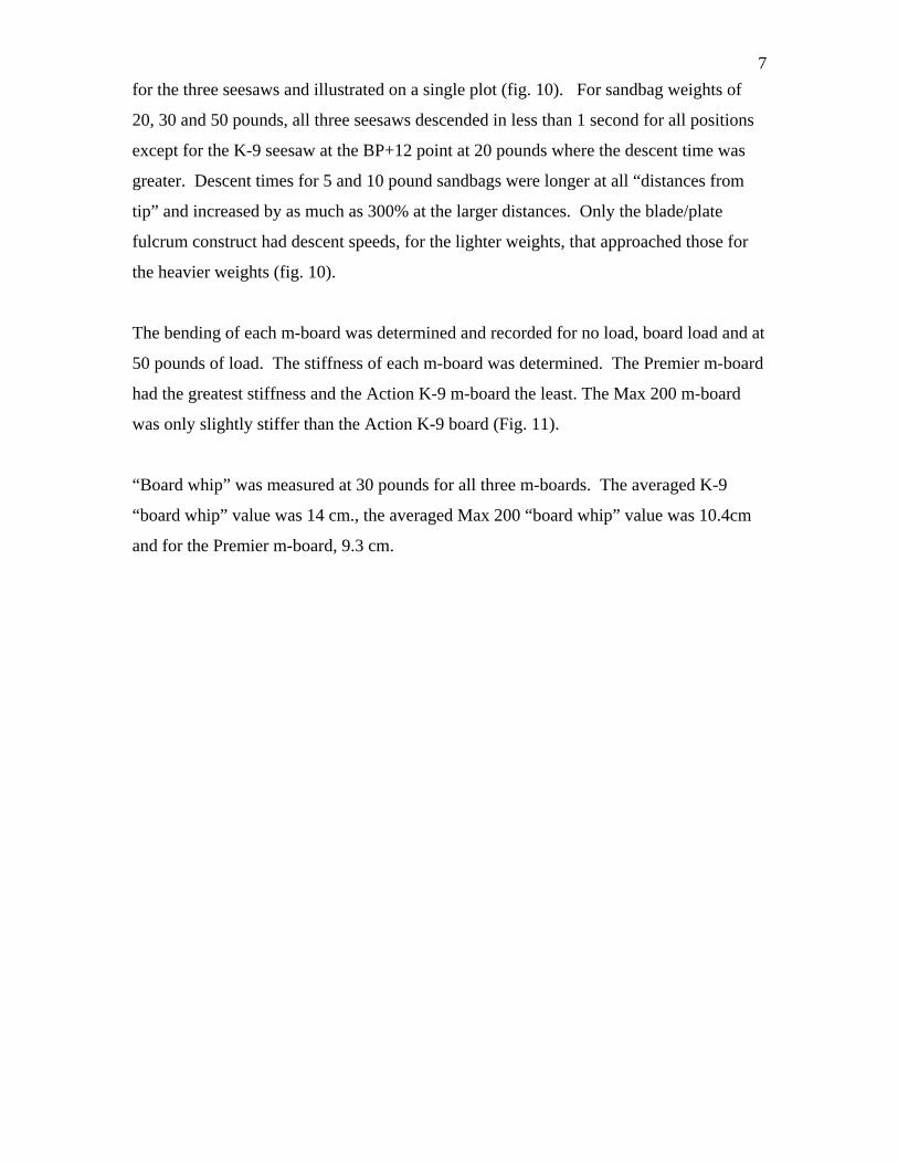
In the third set of tests, the amount of ascending arm induced bending (“board whip”)
was evaluated by tracing the travel of that arm during normal seesaw motion. A
permanent ink marker (Sharpie, Sanford, Bellwood, Illinois) was rigidly fixed to the end
of ascending arm of the m-board. The shaft of the marker was attached parallel to the
surface of the m-board and the tip of the marker was allowed to protrude from the side of
the m-board (fig. 1A and B). In this position the marker traced the path of the ascending
arm onto a cardboard building form (Quikrete, Atlanta, Georgia) that was oriented
vertically and positioned on the floor adjacent to the end of the m-board (fig. 2). A 30-
pound sandbag was placed one foot from the end of the descending arm of the m-board
and that arm was allowed to come to rest on the floor in the seesaw’s final position. With
the seesaw at rest, the elevated position of the ascending arm was marked on the
cardboard form. The seesaw was then placed in its starting position and the weighted
descending arm was dropped, allowing the protruding tip of the marker to trace the path
of the ascending arm along the cardboard form. The point of maximum induced bending
of the ascending arm was marked and the distance (board whip) from that maximum
point to the initial, elevated position of the ascending arm was then measured. The test
was repeated three times for each seesaw and the values for the individual seesaws were
averaged. A vertical contribution from lifting of the base was prevented by stabilizing
each seesaw. Prior to testing, 200-pounds of crushed stone (in 50-pound bags) was
placed on each base. Placing bags of crushed stone on both the vertical member and foot
components prevented separation of the Premier base.
RESULTS
All three seesaws complied with the specifications for size, height of pivot, construction
and speed of descent set by the AKC2, NADAC3 and USDAA4 (Appendix 1). The Max
200 m-board (a plywood board joined to an extruded aluminum beam) weighed an
average of 46.8 pounds and the base averaged 31.3 pounds. The Action K-9 m-board (a
plywood board supported on the undersurface by a square tube steel frame) weighed an
6
average of 47 pounds and the base averaged 17.2 pounds. The m-board from Premier (a
plywood board supported on the undersurface by a wooden frame) weighed an average of
40.6 pounds and the base averaged 21.2 pounds.
Concentric pieces of tubular steel formed the pivot assembly of the Max 200 seesaw (fig.
3A and 3B). The inner steel tube was fixed to the support base. The outer steel tube was
welded to a flat plate that allowed for fixation of the outer pivot tube to the m-board. The
support base was formed with square steel tubing and was adjustable. For this evaluation
the base was assembled and the connector chain adjusted so that the pivot point was 24
inches above the floor. When assembled and in starting position, the tip of the
descending arm was 43 inches from the floor.
A square steel tube that rotated on a fixed round steel tube formed the pivot assembly of
the Action K-9 seesaw (fig. 4A and 4B). The square tube was firmly welded to the frame
of the m-board. The inner round tube extended beyond the square tube and was fixed to
the base by pins. The support base was formed by two rigid triangles made of tubular
steel, one on either side of the board and pivot assembly. The pivot assembly of the
assembled seesaw was positioned 22 ½ inches above the surface. When assembled and
in the starting position the tip of the descending arm was 42 inches from the floor.
The pivot assembly of the Premier seesaw was formed by a right angle plate resting on a
vertical steel blade and was 24 ½ inches above the ground (fig. 5A and 5B). The
assembly was captured on its ends to prevent dislodging. The bottom of the blade was
welded to a horizontal plate, which enabled fixation of the blade/plate assembly to a base
that was formed from wood. The blade/plate assembly was fixed to a vertical “A” shaped
support. The support was held in the vertical position by two wooden feet. The vertical
support slid into channels in the feet and was held in the channels by plates that were
fixed in place with machine bolts and wing nuts (fig. 6). The fixation in the channel was
not rigid. When assembled and in the starting position the tip of the descending arm was
45 ¼ inches above the ground.
The results of the drop tests for a known load for each seesaw were plotted as “distance
from tip” versus “time” (fig. 7, 8 and 9). Drop tests at 5 and 30 pounds were compared
7
for the three seesaws and illustrated on a single plot (fig. 10). For sandbag weights of
20, 30 and 50 pounds, all three seesaws descended in less than 1 second for all positions
except for the K-9 seesaw at the BP+12 point at 20 pounds where the descent time was
greater. Descent times for 5 and 10 pound sandbags were longer at all “distances from
tip” and increased by as much as 300% at the larger distances. Only the blade/plate
fulcrum construct had descent speeds, for the lighter weights, that approached those for
the heavier weights (fig. 10).
The bending of each m-board was determined and recorded for no load, board load and at
50 pounds of load. The stiffness of each m-board was determined. The Premier m-board
had the greatest stiffness and the Action K-9 m-board the least. The Max 200 m-board
was only slightly stiffer than the Action K-9 board (Fig. 11).
“Board whip” was measured at 30 pounds for all three m-boards. The averaged K-9
“board whip” value was 14 cm., the averaged Max 200 “board whip” value was 10.4cm
and for the Premier m-board, 9.3 cm.
8
DISCUSSION
Observations of the seesaw’s motion suggest that this obstacle responds differently to
varying loads. Not only does a single design react differently to load variations, but also
different designs perform differently. The demand for increased speed on an agility
course has created the need for a seesaw that performs quickly and predictably. If dogs
are to rapidly and safely traverse this obstacle, then board bend,” board whip” and base
response must be consistent from design to design. In addition, methods need to be in
place to accurately assess the performance of the seesaw obstacle so that predictable
motion can be assured. It was the goal of this study to understand the factors that
influence a seesaw’s performance, to determine how to evaluate that performance and,
lastly, to develop a set of criteria for the design of an optimal competition seesaw
obstacle.
Each seesaw incorporated a modified board; each board stiffened using a different
structural solution. The Premier m-board construct is stiffened by using wood supports,
fixed on their longer dimension, to the periphery of the board. The K-9 board is stiffened
with a steel square tube ladder. Transverse members give the ladder dimensional stability
but contribute less to stability along the length of the board. The Max 200 m-board was
stiffened using a longitudinally oriented extruded aluminum member. The similarity of
this aluminum support to an “I” beam is notable and stiffens this m-board with a very low
profile.
“Board whip” appeared to be a function of the stiffness of the m-board. In this study, the
less stiff m-boards (K-9, Max 200) were associated with greater amounts of “board whip”
resulting in catapulting of their loads-the sandbag bounced off the end of the m-board.
All three m-boards still had to dissipate the energy developed in the ascending arm. This
energy was transferred to the base, which resulted in hopping of two of the seesaws.
However, in one case, the Premier seesaw, the linkage in the base dissipated the upward
force, and whipping, catapulting and hopping was minimal.
9
Each seesaw used a different fulcrum design. The Premier seesaw used a captured
blade/plate assembly, whereas the K-9 and Max 200 obstacles used tube within a tube
designs. The concentric round within a round tube used by Max 200 was closely fit
whereas the round within a square used by K-9 was less snugly fit. These approaches
resulted in three different interactions at the fulcrum assembly.
Fulcrum design influences the speed at which the m-board descends. For two designs
(fig. 10) it is evident that smaller loads take longer to fully displace the descending arm.
For the fulcrums with square on round tube or round on round tube assemblies, as the
leverage decreases (the distance of the load from the end increases), the descending arm
slows even more. When light loads were applied at increasing distances from the end,
the descent of the m-board slowed considerably. In contrast, the low resistance fulcrum
had less effect on the rate of descent of the m-board for both light and heavy loads,
applied at varying distances from the board end (fig. 10).
Finally, the degree to which a seesaw obstacle is anchored to the ground is no small
matter. The more rigid the fixation of the seesaw to the surface, the more energy stays in
the board, enhancing “board whip” and catapulting. When the seesaw base is less firmly
fixed, lifting of the base dissipates board energy. Hopping of the obstacle can be a by-
product. In one design (Premier), internal movement of the base components enabled
the dissipation of board energy while virtually eliminating base hopping.
All three seesaws tested were well designed and carefully constructed. All three were
easily assembled or taken apart for transport. Each seesaw was consistent in its
performance but varied when compared to each other. And that is the issue. For dogs to
perform reliably, equipment needs to perform in a predictable way. The sport is evolving
past the days where the subtleties of a venue were part of the challenge. High speed and
precise technique demands predictable and reliable performance from the equipment used
in the game. It is important that the governing bodies narrow their specifications so that
designers and manufacturers can build seesaw obstacles that perform similarly for all
dogs.
10
RECOMMENDATIONS
1. It is important that the sport’s governing bodies establish a more precise set of
specifications for the seesaw obstacle that include the stiffness of the board and the
response of the obstacle to a variety of load conditions. This will allow a dog to
anticipate a predictable performance from the obstacle. A single maximum time limit
for a single load does not adequately characterize the performance of a seesaw
obstacle.
2. In an effort to insure that a seesaw obstacle’s performance is similar for both small
and large dogs, we recommend using blade/plate fulcrums. Their use will avoid the
frictional effects of the tube on tube assemblies and the variations in response to
different loads that are a byproduct.
3. Although stiffer m-boards exhibit less “board whip” (and “catapulting”), “launching”
of the base remains a problem. Incorporating force attenuators into the base can
eliminate launching.
11
APPENDIX 1
AKC Specifications2
The Seesaw consists of a plank (or panel) made of wood or a fabricated material that can
be properly surfaced and is supported near the center by a base that acts as a fulcrum. The
plank is 12 inches wide with a 1-inch tolerance, and 12 feet long. The base extends at
least 2 inches past the sides of the plank with a gap not to exceed 4 inches so that dogs
can see the pivot point, with the exception of the ground support, which may be wider.
The plank is balanced so that it hits the ground in less than 3 seconds when a 3-pound
weight is placed 12 inches from the raised end. The height of the Seesaw measured to the
top of the board at the pivot is 24 inches plus or minus 2 inches. The top surface of the
plank is painted and has a rough, non-slip surface. Glossy paint is not allowed.
Alternating layers of sand and flat, latex paint is recommended.) Slats are not allowed on
the seesaw. Contact Zones, 42 inches long, are painted on each end of the plank with a
1/4-inch tolerance, using the color specification described for the A-Frame.
= As of September 2006.
NADAC Specifications3 Contact obstacles should always provide good traction for the dogs without being too
rough as to damage the dog’s pads. Surfaces must be maintained on a regular basis so
that dogs will not slip when performing these obstacles.
Most equipment builders have found that products such as Skid-Free, No-Skid, Skid-Tex, Deck-Tec or other such products will provide a better traction surface than using a large, coarse sand mixture. Most of these products, when mixed heavily with paint, will provide a non-slip surface that also works well when wet.
Rubber surfacing may be used, but MUST be first approved by NADAC.
All contact zones shall be painted yellow, with the remainder of the ramps painted a
contrasting color.
Contact Obstacle
Ramp Length
Ramp Width
Height Contact Zone
Length
Seesaw 12 feet 12 inches 24 inches to top of board at pivot
42 inches
12
Slats are not allowed on the contact equipment.
A good, non-slip surface is required, so dogs have traction on the ramp surface.
Contact Obstacle
Ramp Length
Ramp Width
Height Contact Zone
Length
Teeter Totter 12 feet
12 inches
12 inches is required after
8/1/2006
24 inches at the center of the top
of the teeter board
42 inches
13
USDAA Specifications4 The see-saw (sic) shall consist of a sturdy plank measuring approximately 12 feet
(365cm) in length and measuring between 11 inches (28 cm) and 12 inches (31cm) in
width. The plank shall be supported in the middle by a sturdy base that may be capable
of being securely anchored or weighted to the ground and that shall be visible to the dog
when approaching the ramp from the front on a straight line. The elevation at the plank’s
pivot point shall be between 24 inches (61cm) and 27 inches (68cm) above the ground.
The last 36 inches (915mm) of each end of the plank shall be designated as a safety
contact zone, shall be painted yellow and be a significant contrast to the primary obstacle
color to form a distinct top line. The edge of the zone shall be on the top of the ramp,
extend a reasonable depth onto the sides and have no other banding, insignia or other
markings within twelve inches of the top line. White is not a permissible color.
The plank surface shall be roughened for adequate traction under wet conditions but shall
not be hazardous to dogs’ pads. Rubber or similar matting shall not be permitted. Flat
paint is strongly recommended so that traction is not compromised.
*See-saw base must be visible on approach.
Contact Obstacle
Ramp Length
Ramp Width
Height Contact Zone
Length
See-saw* 12 feet 11 inches- 12 inches
24 inches – 27 inches
36 inches
14
Figure 1A-End View of Test 3 Setup
Figure 1B-Side View of Test 3 Setup
15
Point of Maximum Induced Bending Initial Position of Elevated Arm
Figure 2 Marker Trace on Cardboard Building Form
16
Figure 3A Max 200 Base
Figure 3B Max 200 M-Board Attachment Plates
17
Figure 4A Action K-9 base
Figure 4B Action K-9 M-Board Attachment to Outer Component of Fulcrum
18
Figure 5A Premier Base
Figure 5B Angle Plate Component of Fulcrum of Premier Board
19
Figure 6 Close-up of Premier Base
K-9 SEESAW WITH BAL PTS
0
0.5
1
1.5
2
2.5
3
0 1 2 3 4 5 6
FEET FROM TIP
SE
CS
TIP
TO
GR
OU
ND
5 lbs
10 lbs
20 lbs
30 lbs
50 lbs
Figure 7
20
PREMIER SEESAW WITH BAL PTS
0
0.5
1
1.5
2
2.5
3
0 1 2 3 4 5 6
FEET FROM TIP
SE
CS
TIP
TO
GR
OU
ND
5 LBS
10 LBS
20 LBS
30 LBS
50 LBS
MAX200 SEESAW WITH BAL PTS
0
0.5
1
1.5
2
2.5
3
0 1 2 3 4 5 6
FEET FROM TIP
SE
CS
TIP
TO
GR
OU
ND
5 lbs
10 lbs
20 lbs
30 lbs
50 lbs
Figure 8
Figure 9
21
MAX200/PREMIER/K-9@ 5 and 30
0
0.5
1
1.5
2
2.5
3
0 1 2 3 4 5 6
FEET FROM TIP
SE
CS
TIP
TO
GR
OU
ND
Max 5 lbs"""
Premier 5 lbs"
K 9 5 lbs"
Max 30 lbs"
Premier 30 lbs"
K9 30 lbs
Figure 10
Figure 11
Premier EI = 47,235 N-M2 Action K-9 EI = 27,991 N-M2 Max200 EI = 28,341 N-M2
22
REFERENCES 1. Webster’s New World College Dictionary-Fourth Edition, Michael Agnes Editor in Chief, Wiley Publishing, Inc., 2002, Cleveland, Ohio. 2. Regulations for Agility Trials, published by the American Kennel Club, Amended February 11, 2005. 3. NADAC website. 4. USDAA website. RESEARCHERS Peter A. Torzill Ph.D
Director Laboratory of Soft Tissue Biomechanics Senior Scientist and Director,
Laboratory for Soft Tissue Research, Research Division, Hospital for Special Surgery
Professor of Applied Biomechanics in Orthopaedic Surgery, Department of
Orthopaedics, Weill Medical College of Cornell University, New York, NY