Effect of shear, compaction and nesting on permeability of the orthogonalplain-weave fabric preforms
M. Grujicica,∗, K.M. Chittajallua, Shawn Walshba Department of Mechanical Engineering, Clemson University, 241 Engineering Innovation Building, Clemson, SC 29634, USA
b Army Research Laboratory—WMRD AMSRL-WM-MD, Proving Ground, Aberdeen, MD 21005-5069, USA
Received 10 October 2003; received in revised form 9 March 2004; accepted 26 March 2004
Over the last two decades, processing of high-performancepolymer-matrix composites via the use of modern resin-injection technologies has made major advances and ex-panded from its aerospace roots to military and diversecivil applications. At the same time, processing science hasbecome an integral part of the composite-manufacturingtechnology so that empiricism and semi-empiricism havegiven way to greater use of computer modeling and sim-ulations of the fabrication processes. Among the mod-ern polymer-matrix composite manufacturing techniques,liquid-molding processes such as resin transfer molding(RTM), vacuum assisted resin transfer molding (VARTM)and structural reaction injection molding (SRIM) have aprominent place. A detailed review of the major liquidmolding processes can be found in the recent work of Lee[1]. One common feature to all these composite fabrica-tion processes is the use of low-pressure infiltration of theporous fabric preforms with a viscous fluid (resin). Con-formation of the fabric preforms to the ridges and recessesin the mold and the applied pressure can induce significant
distortions and deformations in the fabric as well as giverise to shifting of the individual fabric layers and, in turn,cause significant change in local permeability of the pre-form. Since the infiltrating fluid follows the path of leastresistance, local changes in the fabric permeability can havea great influence on the mold filling process influencingthe filling time, the filling completeness and the formationof pores and dry spots. Hence, the knowledge of the effectof various distortion, shearing and shifting modes on thefabric permeability is a critical step toward better designsand control of the liquid molding processes.
Permeability of a porous medium is one of the most im-portant parameters controlling the flow of a fluid throughsuch medium. In simple terms, permeability can be definedas a (tensorial) quantity which relates the local velocity vec-tor of the fluid flow with the associated pressure gradient.In polymer-matrix composite liquid-molding manufactur-ing processes (e.g. in the RTM and the VARTM processes),the porous medium consists of woven- or weaved-fabricpreforms placed in the mold and the fluid flow of in-terest involves preform infiltration with resin. Completeinfiltration of the preform with resin is critical for obtain-ing high-integrity, high-quality composite structures. Theknowledge of the preform permeability and its changesdue to fabric bending, shearing, compression, shifting, etc.
Report Documentation Page Form ApprovedOMB No. 0704-0188
Public reporting burden for the collection of information is estimated to average 1 hour per response, including the time for reviewing instructions, searching existing data sources, gathering andmaintaining the data needed, and completing and reviewing the collection of information. Send comments regarding this burden estimate or any other aspect of this collection of information,including suggestions for reducing this burden, to Washington Headquarters Services, Directorate for Information Operations and Reports, 1215 Jefferson Davis Highway, Suite 1204, ArlingtonVA 22202-4302. Respondents should be aware that notwithstanding any other provision of law, no person shall be subject to a penalty for failing to comply with a collection of information if itdoes not display a currently valid OMB control number.
1. REPORT DATE 2004 2. REPORT TYPE
3. DATES COVERED 00-00-2004 to 00-00-2004
4. TITLE AND SUBTITLE Effect of shear, compaction and nesting on permeability of the orthogonalplain-weave fabric preforms
5a. CONTRACT NUMBER
5b. GRANT NUMBER
5c. PROGRAM ELEMENT NUMBER
6. AUTHOR(S) 5d. PROJECT NUMBER
5e. TASK NUMBER
5f. WORK UNIT NUMBER
7. PERFORMING ORGANIZATION NAME(S) AND ADDRESS(ES) Celmson University,Department of Mechanical Engineering,Clemson,SC,29634
8. PERFORMING ORGANIZATIONREPORT NUMBER
9. SPONSORING/MONITORING AGENCY NAME(S) AND ADDRESS(ES) 10. SPONSOR/MONITOR’S ACRONYM(S)
11. SPONSOR/MONITOR’S REPORT NUMBER(S)
12. DISTRIBUTION/AVAILABILITY STATEMENT Approved for public release; distribution unlimited
13. SUPPLEMENTARY NOTES
14. ABSTRACT Permeability of fabric preforms and its changes due to various modes of the fabric distortion ordeformation as well due to fabric layers shifting and compacting is one of the key factors controllinginfiltration of the preforms with resin within the common polymer-matrix composite liquid-moldingfabrication processes. While direct measurements of the fabric permeability generally yield the mostreliable results, a large number of the fabric architectures used and numerous deformation and layersrearrangement modes necessitates the development and the use of computational models for the predictionof preform permeability. One such model, the so-called lubrication model, is adapted in the present workto study the effect of the mold walls, the compaction pressure, the fabric-tows shearing and the fabriclayers shifting on permeability of the preforms based on orthogonal balanced plain-weave fabrics. Themodel predictions are compared with their respective experimental counterparts available in the literatureand a reasonably good agreement is found between the corresponding sets of results.
15. SUBJECT TERMS
16. SECURITY CLASSIFICATION OF: 17. LIMITATION OF ABSTRACT Same as
Report (SAR)
18. NUMBEROF PAGES
12
19a. NAME OFRESPONSIBLE PERSON
a. REPORT unclassified
b. ABSTRACT unclassified
c. THIS PAGE unclassified
Standard Form 298 (Rev. 8-98) Prescribed by ANSI Std Z39-18
M. Grujicic et al. / Materials Chemistry and Physics 86 (2004) 358–369 359
Nomenclature
f fiber volume fractionh fabric thickness (m)K permeability tensor of the fabric (m2)L length of the quarter unit cell (m)p pressure (Pa)r fiber radius (m)s relative shift of the adjacent fabric layers (m)u x-component of the resin velocity (m s−1)U in-plane resin velocity magnitude (m s−1)v y-component of the resin velocity (m s−1)w z-component of the resin velocity (m s−1)W transverse resin velocity magnitude (m s−1)
Greek symbolsη resin viscosity (N s m−2)θ shear angle (◦)φ relative dimensionless shift of the adjacent
fabric layers
Subscriptsbot quantity associated with the bottom surface
of the fabriccorr quantity corrected for the effect of shear on the
fiber volume fractionlow quantity associated with the lower mold
surface0 quantity associated with un-sheared fabric
preformtop quantity associated with the top surface of the
fabricupp quantity associated with the upper mold
surfaceθ quantity associated with sheared fabric
preform
SuperscriptsB quantity associated with the bottom channelF quantity associated with the fabricT quantity associated with the top channel
is crucial in the design of a composite fabrication process(e.g. in the design of the tool plate, or for placement of theresin injection ports). In general, the most accurate valueof permeability of a porous medium is obtained by directexperimental measurements. However, the number of fab-ric architectures can be quite large and fabric distortionmodes numerous making permeability determinations viathe purely experimental means not a very appealing alterna-tive. In addition, sometimes the experimentally determinedpermeability values reported by different researchers for theapparently identical fabric architectures can differ signif-icantly. Consequently, significant effort has been invested
Fig. 1. A schematic of (a) the top view and (b) the edge view of aone-layer orthogonal plain-weave fabric preform.
over the past decade to develop computational tools whichcan be used, in conjunction with experimental measure-ments, to determine the preform permeability.
For the computational modeling approach to be successfulin predicting permeability of the fabric preforms, it mustinclude, in a correct way, both the actual architecture ofthe fabric and the basic physics of the flow through it. Aschematic of the relatively simple orthogonal plain-weaveone-layer fabric architecture is shown inFig. 1. As seen inFig. 1, the fabric consists of orthogonal (warp and weft) fiberyarns, which are woven together to form an interconnectednetwork. Each yarn, on the other hand, represents a bundleof the individual fibers held together with thread. In addition,the fabric involves a network of empty pores and channels.When a fabric like the one shown inFig. 1is being infiltrated,the resin flows mainly through the pores and the channels.However, since the fabric tows are porous (pores and channelon a finer length scale exist between the fibers in tows), theresin also flows within the yarn. Thus when predicting theeffective permeability of a fabric, the computational modelmust account for both components of the resin flow.
Prediction of the permeability of porous medium has beenthe subject of intense research for at least last two decades.Due to space limitations in this paper, it is not possible to dis-cuss all the models proposed over this period of time. Nev-ertheless, one can attempt to classify the models. One suchclassification involves the following main types of modelsfor permeability prediction in the porous media: (a) the phe-nomenological models based on the use of well establishedphysical concepts such as the capillary flow, e.g.[2,3], or thelubrication flow, e.g.[4]. These models generally performwell within isotropic porous media with a simple architec-ture. (b) The numerical models which are based on numer-ical solutions of the governing differential equations. Thesemodels generally attempt to realistically represent the archi-tecture of the fiber preform but, due to limitations in thecomputer speed and the memory size, are ultimately forcedto the introduction of a number of major simplifications, e.g.
360 M. Grujicic et al. / Materials Chemistry and Physics 86 (2004) 358–369
[5,6]. (c) The models which are based on a balance of thefabric architecture and the flow physics simplifications, en-abling physically based predictions of the preform perme-ability within reasonably realistic fabric architectures. Oneof such models is the one proposed by Simacek and Advani[7]. The model of Simacek and Advani[7] also includes theeffect of important factors such as: (a) the flow within thefiber yarn; (b) nesting in multi-layer fabric; and (c) distor-tion and deformation of the fabric. In the present work, theS model of Simacek and Advani[7] is extended to includethe effect of shear of the fabric tows on the effective volumefraction of fibers.
The organization of the paper is as follows: a briefoverview of the model proposed by Simacek and Advani[7] and its modifications are presented inSection 2. The ap-plication of their model to reveal the role of various fabricdistortion and layers compaction phenomena is presentedand discussed inSection 3. The main conclusions resultedfrom the present work are summarized inSection 4.
2. Computational procedure
2.1. Fabric architecture
In this work, only (un-sheared and sheared) balancedorthogonal plain-weave fabric is considered. Due to thein-plane periodicity, the fabric architecture can be repre-sented using a unit cell. The entire orthogonal plain-weavefabric can then be obtained by repeating the unit cell in thein-plane (x- and y-directions). A schematic of one quarterof a plain-weave unit cell with the appropriate denotationfor the system dimensions are shown inFig. 2. In a typicalplain-weave fabric, the fabric thickness (h) to the quarter cellin-plane dimension (L) ratio,h/L, is small (0.01–0.1), whilethe tow cross-section is nearly elliptical in shape with a large
Fig. 2. Schematic of one quarter of the unit cell for a one-layer balanced orthogonal plain-weave fabric.
(width-to-height) aspect ratio (5 or larger). The geometry ofthe tows within the cell can be described using various math-ematical expressions, e.g.[8], for the top,ztop(x, y), and thebottom,zbot(x, y), surfaces of the fabric, respectively. In thepresent work, the following sinusoidal functions originallyproposed by Ito and Chou[9] are used:
ztop(x, y) = h
2
(sin
2π
Lx + sin
2π
Ly
)(1)
zbot(x, y) = −h
2
(sin
2π
Lx + sin
2π
Ly
)(2)
As pointed out earlier, fiber tows have typically anear-elliptical cross-section and henceEqs. (1) and (2)onlyapproximate the actual tow cross-section shape. Neverthe-less, they are used in the present work since they greatlysimplify permeability calculations in the distorted fabricand are generally considered as a good approximation forthe actual tow cross-section shape.
A simple examination ofFig. 2 shows that within asingle-layer orthogonal plain-weave fabric unit cell, onecan identify three distinct domains:
• the top channel, region T:ztop < z < h/2;• the fabric, region F:zbot < z < ztop;• the bottom channel, region B:−h/2 < z < zbot.
Regions T and B contain only the resin, while region Fcontains both the fiber tows and the resin. The resin flowthrough a unit cell is analyzed in the present paper by firstconsidering the flow within the three regions separately andthen utilizing the matching boundary conditions which en-sure continuity in the pressure and the velocity componentsacross the contact surfaces of the adjacent regions. The resinis considered as a Newtonian (constant density) fluid. Theflows within the top and the bottom channels are assumed tobe of a creeping nature (i.e. the inertial effects are neglected)
M. Grujicic et al. / Materials Chemistry and Physics 86 (2004) 358–369 361
while the flow within the fabric is assumed to be governedby the Darcy’s law (a velocity versus pressure gradient re-lation which eliminates the need for use of the momentumconservation equations).
2.2. Governing equations
2.2.1. Flow within the top and the bottom channelsUnder typical fabric infiltration conditions, the resin flow
within the regions T and B can be considered as a creepingflow in which inertial effects are negligibly small in compar-ison to the viscous effects. Under such conditions, at con-stant temperature, the resin flow can be described by theStokes equations as:
−∂p
∂x+ η
(2∂2u
∂x2+ ∂2u
∂y2+ ∂2u
∂z2+ ∂2v
∂x∂y+ ∂2w
∂x∂z
)= 0 (3)
−∂p
∂y+ η
(2∂2v
∂y2+ ∂2v
∂x2+ ∂2v
∂z2+ ∂2u
∂x∂y+ ∂2w
∂y∂z
)= 0 (4)
−∂p
∂z+ η
(2∂2w
∂z2+ ∂2w
∂x2+ ∂2w
∂y2+ ∂2u
∂z∂x+ ∂2v
∂y∂z
)= 0 (5)
∂u
∂x+ ∂v
∂y+ ∂w
∂z= 0 (6)
wherep is the pressure,u, v andw are respectively thex-,y- and z-components of the resin velocity andη the resinviscosity.
Following the procedure of Simacek and Advani[7],which involves non-dimensionalization of the governingequations, and the use of the conditions:h/L � 1 andWL/Uh ≈ 1 (U andW are (mean) in-plane and transverseresin velocity magnitudes, respectively),Eqs. (3)–(6)canbe simplified to yield:
−∂p
∂x+ η
∂2u
∂z2= 0 (3′)
−∂p
∂y+ η
∂2v
∂z2= 0 (4′)
∂p
∂z= 0 (5′)
∂u
∂x+ ∂v
∂y+ ∂w
∂z= 0 (6′)
Eqs. (3′)-(6′) are generally referred to as “two-dimensionallubrication-flow equations” in which the pressure variationin the z-direction is negligibly small. However, in contrastto the traditional lubrication models, the transverse velocityw (the velocity in thez-direction) is generally not zero (orconstant) in the present case and, consequently, the last termon the left hand side of the continuity equation,Eq. (6′),does not vanish. Nevertheless, this term can be eliminatedby integratingEq. (6′) in thez-direction to yield:∫ zupp
zlow
(∂u
∂x+ ∂v
∂y
)dz + w|zupp − w|zlow = 0 (7)
wherezupp(x, y) andzlow(x, y) are mathematical expressionsfor the upper and the lower surfaces of the channels and theassociated transverse velocities,w|zupp andw|zlow , are givenby the appropriate boundary conditions discussed later.
2.2.2. Flow within the fiber towsThe resin flow through the fabric is described in the
present work using the Darcy’s law for an anisotropic porousmedium as:
u = −1
η
(Kxx
∂p
∂x+ Kxy
∂p
∂y+ Kxz
∂p
∂z
)(8)
v = −1
η
(Kyx
∂p
∂x+ Kyy
∂p
∂y+ Kyz
∂p
∂z
)(9)
w = −1
η
(Kzx
∂p
∂x+ Kzy
∂p
∂y+ Kzz
∂p
∂z
)(10)
∂u
∂x+ ∂v
∂y+ ∂w
∂z= 0 (11)
whereKxx, Kyy, Kzz, Kxy=Kyx, Kxz=Kzx, andKyz=Kzy arethe components of the symmetric tow permeability tensor.
Eqs. (8)–(11)can be simplified under the following as-sumptions: (a)Kxx = Kyy = Kzz and (b)Kyz = Kzx =0. The first assumption is not typically fully justified sincethe longitudinal components of the permeability (Kxx andKyy) are generally larger (up to an order of magnitude) thanthe transverse component (Kzz) of the permeability. How-ever, this assumption greatly simplifies the computationalprocedure and, for simple fabric geometries, it is found,in the present work, that the results are different by only1–2% relative to their more accurately determined counter-parts corresponding toKxx/Kzz = Kyy/Kzz = 10. The sec-ond assumption, on the other hand, is generally expectedto be valid for at least two reasons: (a) for the orthogonalplain-weave architecture of the fabric, the material trans-verse principal direction is expected to be essentially coin-cident with the globalz-axis; and (b) the second assumptionis valid whenever the first assumption is valid. Again fol-lowing the procedure of Simacek and Advani[7], which in-volves non-dimensionalization of the governing equations,and the use of the conditions:h/L � 1 andWL/Uh ≈ 1,Eqs. (8)–(11)become:
u = 0 (8′)
v = 0 (9′)
w = −Kzz
η
∂p
∂z(10′)
∂w
∂z= 0 (11′)
Eqs. (8′)-(11′) indicate that the only non-zero componentof the resin velocity within the fabric is the one in thez-direction and that, at given values of the in-planex- andy-coordinates, this component of the velocity does not varyin thez-direction.
362 M. Grujicic et al. / Materials Chemistry and Physics 86 (2004) 358–369
2.3. Boundary conditions
The following boundary conditions are used for the resinflow problem in the three regions:
• no slip (u = v = w = 0) at the mold walls,z = ±(h/2);• at the fabric/channels contact surfaces,ztop andzbot, the
velocities and the pressure continuity are assumed, i.e.:
φ(in T)|ztop = φ(in F)|ztop (12)
φ(in B)|zbot = φ(in F)|zbot (13)
whereφ = p, u, v, or w.
It should also be noted that, as established in the previoussection,u(in F) = v(in F) = 0. In addition, the definition ofthe (x andy) in-plane boundary conditions is deferred untilthe final system of equations is derived (the next section).
2.4. The final system of equations
The resin velocities in the two channels can be obtained byintegrating twiceEqs. (12) and (13), and using the boundaryconditions given byEqs. (12) and (13)to determine theintegration constants. This procedure yields:
u = ∂p/∂x
η
(z − h
2
)(z − ztop)
v = ∂p/∂y
η
(z − h
2
)(z − ztop)
in regional T (14)
u = ∂p/∂x
η
(z + h
2
)(z − zbot)
v = ∂p/∂y
η
(z + h
2
)(z − zbot)
in region B (15)
The subsequent equations can be simplified by introducingthe following expressions:hT(x, y) = h/2−ztop, hB(x, y) =zbot − h/2, hF(x, y) = ztop − zbot, which denote the heightfields of the top channel and the bottom channels and thethickness field of the fabric, respectively.
Substitution ofEqs. (14) and (15)into the integrated formof the continuity equation,Eq. (7), for the two channelsyields:
wT|z=h/2 − wT|z=ztop
− 1
6η
(∂((hT)3(∂pT/∂x))
∂x+ ∂((hT)3(∂pT/∂y))
∂y
)= 0
(16)
wB|z=zbot − wB|z=−h/2
− 1
6η
(∂((hB)3(∂pB/∂x))
∂x+ ∂((hB)3(∂pB/∂y))
∂y
)= 0
(17)
where superscripts T and B are used to denote the quantitiespertaining to the top and the bottom channels.
The first two terms on the left hand side ofEqs. (16)and (17)are defined by the boundary conditions discussedearlier as:
wT|z=h/2 = 0 (18)
wT|z=ztop = Kzz(pB − pT)
ηhF (19)
wB|z=−h/2 = 0 (20)
wB|z=zbot = Kzz(pB − pT)
ηhF (21)
ConsequentlyEqs. (16) and (17)can be rewritten as
−Kzz(pB − pT)
ηhF
− 1
6η
(∂((hT)3(∂pT/∂x))
∂x+ ∂((hT)3(∂pT/∂y))
∂y
)= 0
(22)
Kzz(pB − pT)
ηhF
− 1
6η
(∂((hB)3(∂pB/∂x))
∂x+ ∂((hB)3(∂pB/∂y))
∂y
)= 0
(23)
Eqs. (22) and (23)represent the final system of equationsconsisting of two coupled linear elliptic partial differentialequations with the pressurespT andpB as dependent vari-ables. To solve these equations, boundary conditions alongthe (x–y) in-plane boundaries of the unit cell must be pre-scribed. For the un-sheared balanced plain-weave fabric ar-chitecture in which the unit cell boundaries are the lines ofgeometrical symmetry, a fixed pressure gradient can be en-forced in one principal direction while requiring periodicityin the pressure distribution in the direction normal to thedirection in which the pressure gradient is prescribed. Thistype of boundary conditions is generally used since it en-ables determination of the off-diagonal (Kxy, Kyz andKxz)components of the effective preform permeability tensor. Amore detailed discussion of the in-plane boundary conditionsis given later in the context of the effect of fabric shearingon the choice of in-plane boundary conditions.
The final system of partial differential equations,Eqs. (22)and (23), contains the thickness fields:hT(x, y), hB(x, y)
andhF(x, y). These fields are defined in the present workusing the analytical expressions for the top and the bottomsurfaces of the fabric preform (Eqs. (1) and (2)). These ex-pressions are generally considered as reasonably good ap-proximations of the actual orthogonal plain-weave fabric ar-chitecture with a near elliptical cross-section area. It shouldbe noted, however, that over-simplification of the fabric ar-chitecture (e.g. using square or circularly shaped tows) maylead to erroneous results and must be avoided. In general,the thickness fields can be constructed using direct exper-imental measurements such as quantitative metallographic
M. Grujicic et al. / Materials Chemistry and Physics 86 (2004) 358–369 363
analysis of consolidated and sectioned parts, e.g.[11], andthrough the use of computerized image analysis of the fab-ric surface, e.g.[12]. The second of these two methods isquite appealing since the image conversion procedure canbe directly coupled with the solution scheme forEqs. (22)and (23).
Due to complexity in thehT(x, y), hB(x, y) andhF(x, y)
functions,Eqs. (22) and (23), cannot be solved analytically.However, finding the numerical solution toEqs. (22) and(23) is relatively straightforward. In the present work, MAT-LAB general-purpose mathematical package[10] and a fi-nite difference method are used to solveEqs. (22) and (23).
OnceEqs. (22) and (23)are solved, the resulting pressurefields can be used, in conjunction withEqs. (14) and (15), tocompute the corresponding in-plane velocity fields in the twochannels. Integration of these velocity fields over the sideboundaries of the quarter unit cell then enables determine ofthe total resin flow rate,Q = [Qx, Qy], through the quarterunit cell in the two principal direction. The components ofthe effective in-plane preform permeability,Keff
xx , Keffyy and
Keffxy are then computed using the two-dimensional Darcy’s
law and the known imposed values of the pressure gradient.
2.5. Application of the model to the multi-layer fabric
The model developed thus far pertains to a single-layerfabric preform. In typical RTM and VARTM processes,the preforms may contain several fabric layers. In suchmulti-layer preforms, nesting and compaction generallyhave a significant effect and must be included when pre-dicting preform permeability. Numerous experiments, e.g.[13,14], confirmed that permeability varies with a numberof layers.
The single-layer model developed in the previous sec-tion can be readily extended to a multi-layer preform. Aschematic of two types of two-layer plain-weave fabric pre-forms is given inFig. 3(a) and (b). The two types are gen-erally referred to as “in-phase” and “out-of-phase” fabricarchitectures or laminates. In the case of ann-layer fabricpreform, if the channels are labeled using consecutive in-tegers (with the bottom channel being denoted as channel“1”), the analytical procedure for a single-layer fabric pre-form used in the previous section yields (n + 1) coupledelliptical partial differential equations withn + 1 unknownpressuresp(1), p(2), . . . , p(n+1) as:
− Kzz
ηhF1(p(2) − p(1)) − 1
6η∇((h(1))3∇p(1)) = 0 (24)
Kzz
ηhFi−1(p(i) − p(i+1)) − Kzz
ηhFi(p(i+1) − p(i))
− 1
6η∇((h(i))3∇p(i)) = 0, i = 2, 3, . . . , n (25)
Kzz
ηhFn(p(n+1) − p(n)) − 1
6η∇((h(n+1))∇p(n+1)) = 0 (26)
Fig. 3. x–z section of a quarter of the unit cell for (a) an in-phase and(b) an out-of-phase two-layer orthogonal plain-weave fabric.
wherehFi (i = 1, . . . , n) denotes the thicknesses of theithfabric layer (numbered starting from the bottom of the mold)andh(i) (i = 1, . . . , n+1) are the heights of the inter-fabricor tool/fabric resin channels (also numbered starting fromthe bottom of the mold). The system of equations definedby Eqs. (24)–(26)is solved using the same computationalprocedure used for the one-layer fabric preform.
When the fabric is sheared in thex-direction, as shownin Fig. 7(b), weft tows are rotated but remain stress free.Consequently, the dimension of the fabric-preform unit cellin the y-direction is altered causing a change in the effec-tive fiber volume fraction in the unit cell. This change in thefiber volume fraction can have a significant effect on pre-form permeability at large shear angles and, hence, must betaken into account. The procedure described below is used tocorrect permeabilities in the sheared fabrics obtained usingthe original model of Simacek and Advani[7] as reviewedin Sections 2.4 and 2.5.
364 M. Grujicic et al. / Materials Chemistry and Physics 86 (2004) 358–369
Fig. 4. (a) Resin channels height and (b) fabric thickness fields in an un-sheared one-layer orthogonal plain-weave fabric preform.
To quantify the permeability correction described above,the Kozeny-Carman relation, e.g.[20], for permeability ofthe porous media with a fibrous architecture is used. Ac-cording to this relation, permeability of such media is givenby:
K = r2(1 − f)3
cf2(27)
where r and f are the fiber radius and the fiber vol-ume fraction, respectively, whilec is a fibrous-mediumarchitecture-dependent constant.
When the fabric preform is sheared in thex-direction byan angleθ, the fiber volume fraction in fabric tows changesas:
fθ = f0
sin(90− θ)(28)
where the angleθ is given in degrees and the subscripts 0andθ are used to denote the value of a respective quantity inthe un-sheared fabric and in the fabric sheared by an angleθ, respectively.
To account for a shear-induced change in the fiber volumefraction, the permeability values for sheared fabric preformsobtained using the models described inSections 2.4 and 2.5,should be multiplied by the following correction factor:
The model developed inSection 2.4is used in this sectionto analyze the pressure distribution within the un-shearedsingle-layer balanced orthogonal plain-weave quarter unit
cell. Due to the symmetry of the unit cell with respect to thez = 0 plane, the pressure distributions within the top andthe bottom resin channels are identical and, hence, there isno transverse flow of the resin through the fabric preform.Also, as established inSection 2.4, there is no variation ofthe pressure in thez-direction within the channels. The vari-ation of the top- and bottom-channel heights and of the fab-ric thickness in thex–y plane within a quarter unit cell, usedas input in the present analysis, are shown inFig. 4(a) and(b), respectively. The variation of the pressure in thex–yplane within the resin channels of a quarter unit cell for thefixed pressure drop of 1.0× 10⁵ in thex-direction is shownin Fig. 5. The pressure distribution (or more precisely its
Fig. 5. Pressure distribution in thex–y plane within a resin channel inthe case of an un-sheared single-layer balanced orthogonal plain-weavefabric preform.
M. Grujicic et al. / Materials Chemistry and Physics 86 (2004) 358–369 365
gradient) at a givenx–y location correlates inversely with thelocal height of the resin channel in order to satisfy the con-tinuity equation. It should be also noted that due to the sym-metry of the fabric geometry with respect to the quarter unitcell boundaries normal to they-direction, zero-flux (i.e. zeropressure gradient) conditions are found in they-direction atthese boundaries.
3.2. Effect of the number of layers in un-shearedplain-weave fabric preforms
The model developed inSection 2.5is used in the presentsection to predict permeability of the balanced un-shearedsingle- and multi-layer orthogonal plain-weave fabric archi-tectures. In all the calculations carried out in this section, aswell as in the calculations carried out in the previous sec-tion, the following unit cell parameter and one-layer fabricthickness values are used:L1 = L2 = L = 0.01 m andh = 0.001 m. Also the transverse permeability of the fibertows is set to a typical (fixed) value,Kzz = 1 × 10⁻¹⁰ m2.
To determine the effect of the number of fabric layerson the effective permeability, the model developed in theprevious section is used for the cases of 1-, 2-, 3-, 5-, 10-and 20-layer in-phase orthogonal balanced plain-weave fab-ric preforms in the absence of layer nesting. The resultsof this calculation are presented inFig. 6. These resultsshow that as the number of layers increases, the permeabil-ity rises but at an ever decreasing rate so that in fabric pre-forms with 10 or more layers, the effect of the number oflayers on permeability becomes insignificant. This findingcan be easily rationalized by recognizing that as the num-ber of layers in the fabric increases, the effect of the bottomand the top resin channels which are more restrictive to thefluid flow (and thus reduce effective preform permeability)decreases.
Number of Fabric Layers in the Preform
Eff
ectiv
eP
refo
rmP
erm
eabi
lity,
m2
0 3 6 9 12 15 18 215E-10
1E-09
1.5E-09
2E-09
2.5E-09
3E-09
Fig. 6. The effect of the number of fabric layers on the effective perme-ability of an un-sheared balanced plain-weave fabric preform.
3.3. Effect of fabric shear on permeability
As pointed out earlier, when the fabric preform is forcedto conform to the ridges and recesses of a mold, it maylocally undergo shear deformation. Such deformation cansignificantly affect local permeability of the preform. Asshown inFig. 7, when a balanced square-cell plain-weavefabric is sheared, two important factors must be consid-ered: (a) the unit cell size increases and to make the calcu-lations of preform permeability manageable, the shear an-gle α = tan−1(m/n) is generally allowed to take only thevalues corresponding to relatively small integersm and n;and (b) the boundaries of the unit cell, unlike the case ofthe initial square-shape unit cell, are no longer the lines ofsymmetry of the fabric structure. Consequently, the bound-ary conditions imposed along the boundaries of the unit cellhave to be modified relative to those used in the case of theun-sheared unit cell. For instance, if a fixed pressure dropis applied in thex-direction, the symmetry conditions alongthe unit cell boundaries normal to they-coordinate requirethat zero pressure-gradient boundary conditions be appliedin the y-direction. In the case of a sheared fabric preform,on the other hand, the unit cell boundaries normal to they-direction are not any longer the lines of symmetry of thefabric architecture and, hence, only the periodic boundarycondition (the corresponding pressure values along the two
Fig. 7. Effect of fabric shearing on the size of the quarter unit cell (denotedusing heavy dashed lines) in balanced plain-weave fabric architectures:(a) un-sheared fabric; (b) fabric sheared by an angleα = tan−1(1/3) inthe x-direction.
366 M. Grujicic et al. / Materials Chemistry and Physics 86 (2004) 358–369
Shear Angle, deg
Pre
form
Per
mea
bilit
yC
ompo
nen
ts,m
2
0 5 10 15 20 25 300
2E-10
4E-10
6E-10
8E-10
1E-09
Kxx [21]
Kxy
Kyy [21]
Kyx
Kyy
Kxx
Fig. 8. The effect of shear on permeability of a single-layer balancedorthogonal plain-weave fabric preform.
unit-cell boundaries normal to they-direction are identical)can be applied.
The effect of shear deformation (measured by the mag-nitude of the shear angleα) on the effective permeabil-ity of single-layer plain-weave fabric preforms is displayedin Fig. 8. An example of the variation of the top- andbottom-channel heights and of the fabric thickness in thex–y plane within a quarter unit cell, used as input in thepresent analysis, are shown inFigs. 9(a) and (b), respec-tively. For comparison, the experimental values of preformpermeabilities obtained in Ref.[8] are also shown inFig. 8.While the agreement between the corresponding computa-tional and the experimental values is only fair, the effect ofshear deformation on preform permeability appears to bequite well predicted by the model. In addition, the corre-sponding computed values of the in-plane off-diagonal (Kxy
and Kyx) elements of the effective permeability are veryclose as required by symmetry of the orthogonal plain-weavefabric architecture.
Fig. 9. (a) Resin channels height and (b) fabric thickness fields in a one-layer orthogonal plain-weave fabric preform subjected to shear in thex-directionby an angle ofα = tan−1(1/3).
Linear Fab
ric
Th
ickn
ess
Compaction Pressure
Non-linear
Linear
Fig. 10. A typical compaction-pressure vs. preform-thickness curve for aplain-weave fabric architecture.
3.4. Effect of preform compaction on permeability
When the fabric is subjected to compression during moldclosing in the RTM process or during evacuation of the vac-uum bag in the VARTM process, it undergoes a number ofchanges such as: the cross-section of the fiber tow flattens,the pores and gaps between the fibers inside tows as well asbetween individual tows are reduced, the tows undergo elas-tic deformation, inter-layers shifting (nesting), etc. A typicalcompression-pressure versus preform thickness curve for awoven fabric is depicted inFig. 10 [15]. The curve shown inFig. 10has three distinct parts: two linear and one nonlinear.In the low-pressure linear and the nonlinear portions of thepressure versus thickness curve, preform compaction is dom-inated by a reduction of the pore and the gap sizes betweenthe fibers in tows. In the high-pressure linear region of thepressure versus thickness curve, on the other hand, preform
M. Grujicic et al. / Materials Chemistry and Physics 86 (2004) 358–369 367
compaction involves mainly tow bending and nesting. Typ-ical liquid molding processes such as RTM or VARTM in-volve pressures which correspond to the high-pressure lin-ear pressures versus thickness region. Hence, the effect offabric compaction on permeability of the fabric preform as-sociated with the high-pressure linear compaction regime isinvestigated in this section.
To quantify the effect of preform compaction (in thehigh-pressure linear region) on permeability of the balancedorthogonal plain-weave fabric, the beam-bending-basedmicro-mechanical model developed in a series of papers byChen and Chou[16–18] is utilized in the present work. Themodel of Chen and Chou[16–18] is based on a number ofwell-justified assumptions such as: (a) the fabric is consid-ered to extend indefinitely in thex–y plane and, hence, canbe represented using the unit cells such as the one shownin Fig. 2; (b) tows in the fabric are treated as a transverselyisotropic solid material; (c) the fabric is subjected to thecompaction pressure only in the through-the-thickness di-rection, and can freely adjust its shape in thex–y plane;(d) since the compaction analyzed corresponds to the high-pressure linear region, no voids or gaps are assumed toexist between the fibers in tows or between the tows; (e)during fabric compaction, the cross-section area of thetows is assumed to remain unchanged but the shape of thecross-section undergoes a change; and (f) as compactionproceeds, the deformation of the tows leads to an increasein the effective volume fraction of the fibers in the fabricand, in the limit of complete compaction of the tows, thevolume fraction of the fibers in the fabric becomes equal tothat in the individual tows.
In order to derive a relationship between the reductionin the fabric thickness, the effective volume fraction of thefibers and various distributions and magnitudes of the ap-plied compaction pressure, Chen and Chou[16–18]applieda simple procedure from the solid mechanics beam theory.Toward that end, the one-quarter unit cell shown inFig. 2 isfirst simplified by replacing the two warp and the two wefttows with four beams. Next based on the symmetry of thesimplified model, it is shown that the problem can be furthersimplified using a single beam and the appropriate distribu-tion of the applied and contacting pressures (Fig. 11). Themodel of Chen and Chou[16–18] is utilized in the presentwork to compute the effect of the compaction pressure onthe channel heights (hT(x, y) andhB(x, y)) and on the fabricthickness,hF(x, y) fields. These fields are, in turn, used inthe lubrication model presented in theSection 2.4to quan-tify the effect of fabric compaction on the effective perme-ability of a one-layer orthogonal plain-weave fabric.
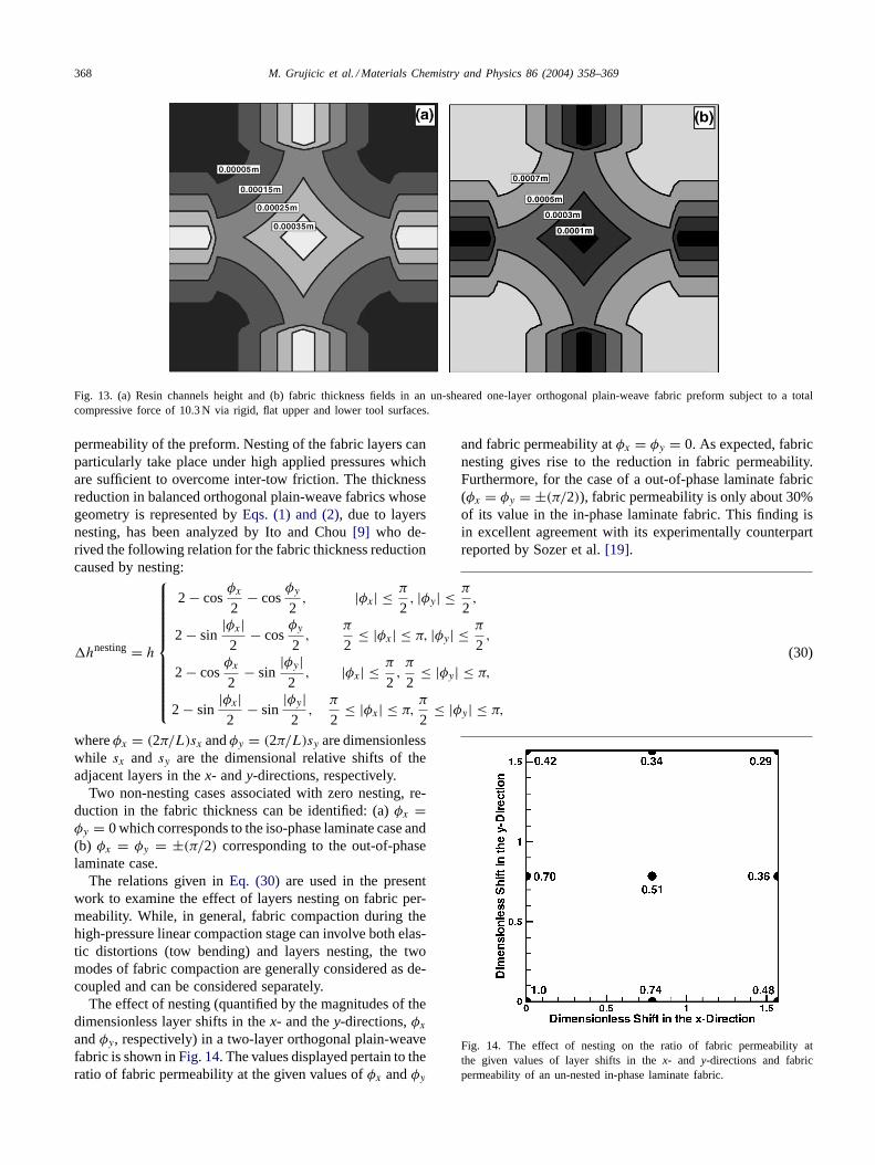
The effect of the compaction force applied to the upperand the lower (rigid and flat) molds on the effective perme-ability of a one-layer orthogonal plain-weave fabric is dis-played inFig. 12. In these calculations, the Young’s modulusis assigned a value of 22 GPa and a sinusoidal distribution ofthe applied and the contacting pressures is assumed[18]. Anexample of the variation of the top- and the bottom-channel
Fig. 11. A schematic of the pressure distribution on a curved beam usedin the calculation of permeability of un-sheared one-layer orthogonalplain-weave fabrics.
heights and of the fabric thickness in thex–y plane withina quarter unit cell, used as input in the present analysis, areshown inFig. 13(a) and (b), respectively. For comparison,the experimental results reported by Sozer et al.[19] are alsoshown inFig. 12. It is seen that a reasonably good agree-ment exists between the both the magnitude of the predictedpreform permeability and its change with the applied com-paction force.
3.5. Effect of layer nesting
As mentioned earlier shifting of fabric layers followedby their more compact packing (the phenomenon generallyreferred to as layers “nesting”) can have a major effect onthe effective fiber density in the preform and, hence, on
Compaction Force, N
Eff
ectiv
eP
refo
rmP
erm
eabi
lity,
m2
0 2 4 6 8 10 12 14 165E-10
5.5E-10
6E-10
6.5E-10
7E-10
7.5E-10
8E-10
Ref. [19]
This Work
Fig. 12. Effect of compaction (represented by the magnitude of thecompaction force) on permeability of a one-layer un-sheared orthogonalplain-weave fabric preform.
368 M. Grujicic et al. / Materials Chemistry and Physics 86 (2004) 358–369
Fig. 13. (a) Resin channels height and (b) fabric thickness fields in an un-sheared one-layer orthogonal plain-weave fabric preform subject to a totalcompressive force of 10.3 N via rigid, flat upper and lower tool surfaces.
permeability of the preform. Nesting of the fabric layers canparticularly take place under high applied pressures whichare sufficient to overcome inter-tow friction. The thicknessreduction in balanced orthogonal plain-weave fabrics whosegeometry is represented byEqs. (1) and (2), due to layersnesting, has been analyzed by Ito and Chou[9] who de-rived the following relation for the fabric thickness reductioncaused by nesting:
�hnesting= h
2 − cosφx
2− cos
φy
2, |φx| ≤ π
2, |φy| ≤ π
2,
2 − sin|φx|2
− cosφy
2,
π
2≤ |φx| ≤ π, |φy| ≤ π
2,
2 − cosφx
2− sin
|φy|2
, |φx| ≤ π
2,π
2≤ |φy| ≤ π,
2 − sin|φx|2
− sin|φy|2
,π
2≤ |φx| ≤ π,
π
2≤ |φy| ≤ π,
(30)
whereφx = (2π/L)sx andφy = (2π/L)sy are dimensionlesswhile sx and sy are the dimensional relative shifts of theadjacent layers in thex- andy-directions, respectively.
Two non-nesting cases associated with zero nesting, re-duction in the fabric thickness can be identified: (a)φx =φy = 0 which corresponds to the iso-phase laminate case and(b) φx = φy = ±(π/2) corresponding to the out-of-phaselaminate case.
The relations given inEq. (30) are used in the presentwork to examine the effect of layers nesting on fabric per-meability. While, in general, fabric compaction during thehigh-pressure linear compaction stage can involve both elas-tic distortions (tow bending) and layers nesting, the twomodes of fabric compaction are generally considered as de-coupled and can be considered separately.
The effect of nesting (quantified by the magnitudes of thedimensionless layer shifts in thex- and they-directions,φx
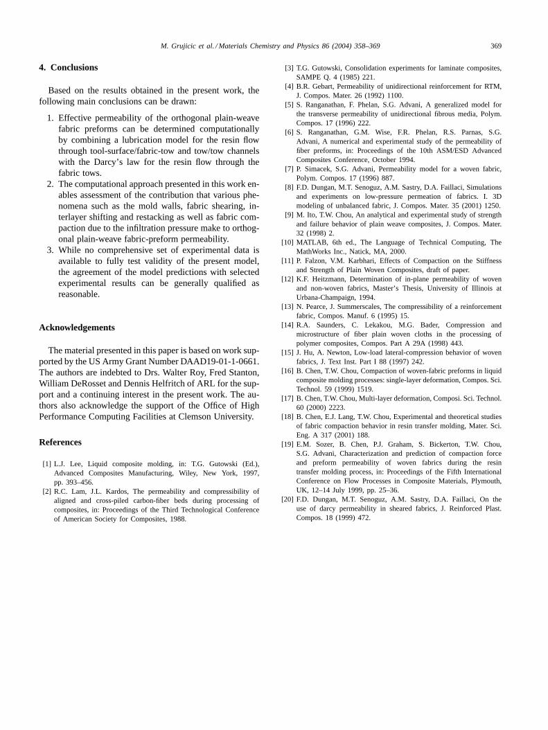
andφy, respectively) in a two-layer orthogonal plain-weavefabric is shown inFig. 14. The values displayed pertain to theratio of fabric permeability at the given values ofφx andφy
and fabric permeability atφx = φy = 0. As expected, fabricnesting gives rise to the reduction in fabric permeability.Furthermore, for the case of a out-of-phase laminate fabric(φx = φy = ±(π/2)), fabric permeability is only about 30%of its value in the in-phase laminate fabric. This finding isin excellent agreement with its experimentally counterpartreported by Sozer et al.[19].
Fig. 14. The effect of nesting on the ratio of fabric permeability atthe given values of layer shifts in thex- and y-directions and fabricpermeability of an un-nested in-phase laminate fabric.
M. Grujicic et al. / Materials Chemistry and Physics 86 (2004) 358–369 369
4. Conclusions
Based on the results obtained in the present work, thefollowing main conclusions can be drawn:
1. Effective permeability of the orthogonal plain-weavefabric preforms can be determined computationallyby combining a lubrication model for the resin flowthrough tool-surface/fabric-tow and tow/tow channelswith the Darcy’s law for the resin flow through thefabric tows.
2. The computational approach presented in this work en-ables assessment of the contribution that various phe-nomena such as the mold walls, fabric shearing, in-terlayer shifting and restacking as well as fabric com-paction due to the infiltration pressure make to orthog-onal plain-weave fabric-preform permeability.
3. While no comprehensive set of experimental data isavailable to fully test validity of the present model,the agreement of the model predictions with selectedexperimental results can be generally qualified asreasonable.
Acknowledgements
The material presented in this paper is based on work sup-ported by the US Army Grant Number DAAD19-01-1-0661.The authors are indebted to Drs. Walter Roy, Fred Stanton,William DeRosset and Dennis Helfritch of ARL for the sup-port and a continuing interest in the present work. The au-thors also acknowledge the support of the Office of HighPerformance Computing Facilities at Clemson University.
References
[1] L.J. Lee, Liquid composite molding, in: T.G. Gutowski (Ed.),Advanced Composites Manufacturing, Wiley, New York, 1997,pp. 393–456.
[2] R.C. Lam, J.L. Kardos, The permeability and compressibility ofaligned and cross-piled carbon-fiber beds during processing ofcomposites, in: Proceedings of the Third Technological Conferenceof American Society for Composites, 1988.
[4] B.R. Gebart, Permeability of unidirectional reinforcement for RTM,J. Compos. Mater. 26 (1992) 1100.
[5] S. Ranganathan, F. Phelan, S.G. Advani, A generalized model forthe transverse permeability of unidirectional fibrous media, Polym.Compos. 17 (1996) 222.
[6] S. Ranganathan, G.M. Wise, F.R. Phelan, R.S. Parnas, S.G.Advani, A numerical and experimental study of the permeability offiber preforms, in: Proceedings of the 10th ASM/ESD AdvancedComposites Conference, October 1994.
[7] P. Simacek, S.G. Advani, Permeability model for a woven fabric,Polym. Compos. 17 (1996) 887.
[8] F.D. Dungan, M.T. Senoguz, A.M. Sastry, D.A. Faillaci, Simulationsand experiments on low-pressure permeation of fabrics. I. 3Dmodeling of unbalanced fabric, J. Compos. Mater. 35 (2001) 1250.
[9] M. Ito, T.W. Chou, An analytical and experimental study of strengthand failure behavior of plain weave composites, J. Compos. Mater.32 (1998) 2.
[10] MATLAB, 6th ed., The Language of Technical Computing, TheMathWorks Inc., Natick, MA, 2000.
[11] P. Falzon, V.M. Karbhari, Effects of Compaction on the Stiffnessand Strength of Plain Woven Composites, draft of paper.
[12] K.F. Heitzmann, Determination of in-plane permeability of wovenand non-woven fabrics, Master’s Thesis, University of Illinois atUrbana-Champaign, 1994.
[13] N. Pearce, J. Summerscales, The compressibility of a reinforcementfabric, Compos. Manuf. 6 (1995) 15.
[14] R.A. Saunders, C. Lekakou, M.G. Bader, Compression andmicrostructure of fiber plain woven cloths in the processing ofpolymer composites, Compos. Part A 29A (1998) 443.
[15] J. Hu, A. Newton, Low-load lateral-compression behavior of wovenfabrics, J. Text Inst. Part I 88 (1997) 242.
[16] B. Chen, T.W. Chou, Compaction of woven-fabric preforms in liquidcomposite molding processes: single-layer deformation, Compos. Sci.Technol. 59 (1999) 1519.
[18] B. Chen, E.J. Lang, T.W. Chou, Experimental and theoretical studiesof fabric compaction behavior in resin transfer molding, Mater. Sci.Eng. A 317 (2001) 188.
[19] E.M. Sozer, B. Chen, P.J. Graham, S. Bickerton, T.W. Chou,S.G. Advani, Characterization and prediction of compaction forceand preform permeability of woven fabrics during the resintransfer molding process, in: Proceedings of the Fifth InternationalConference on Flow Processes in Composite Materials, Plymouth,UK, 12–14 July 1999, pp. 25–36.
[20] F.D. Dungan, M.T. Senoguz, A.M. Sastry, D.A. Faillaci, On theuse of darcy permeability in sheared fabrics, J. Reinforced Plast.Compos. 18 (1999) 472.