a Department of Mechanical Engineering, Kyushu University, 744 Moto-oka, Nishi-ku, Fukuoka, 819-0395 Japan b Research Center for Hydrogen Industrial Use and Storage (HYDROGENIUS), 744 Moto-oka, Nishi-ku, Fukuoka, 819-0395 Japan
c International Institute for Carbon-Neutral Energy Research (I2CNER), 744 Moto-oka, Nishi-ku, Fukuoka, 819-0395 Japan d NSK Ltd., 1-5-50 Kugenuma-Shimmei, Fujisawa-shi, Kanagawa, 251-8501 Japan
e International Research Center for Hydrogen Energy, 744 Moto-oka, Nishi-ku, Fukuoka, 819-0395 Japan
Flaking, which is a typical fracture mode of a roller bearing, is a fatigue fracture associated with shear-mode (modes II and III) crack growth (Murakami (1993)). Therefore, it would be desirable if the flaking strength could be handled as a crack problem, similar to the metal fatigue problems responsible for mode I crack growth. For large roller bearings especially, such as those used in wind turbine generators and large industrial machines, it is difficult to provide statistical reliability assurance because a series of fatigue tests using such large bearings would be difficult in terms of cost. Therefore, there is a need to develop a new strength evaluation method based on the fracture mechanism and crack growth property. In fact, many studies have been conducted in the last three decades to establish this type of evaluation method (Murakami et al. (1993); Otsuka et al. (1994); Matsunaga et al. (2009), (2011) Matsunaga (2010)). However, the crack growth and resistance properties of rolling contact fatigue still present many unsolved problems, chiefly because it is extremely difficult to make continuous observations beginning from crack initiation, through crack growth, to final fracture. Given this situation, therefore, a specimen with a crack starter (e.g. small hole, groove, indentation etc.) has been used to enable a successive observation of the fracture process. (Cheng et al. (1993); Dommarco et al. (2002), (2006); Fujii et al. (2002); Kida et al. (2004), (2006); da Mota et al. (2008)).
In this study, rolling contact fatigue tests were performed on JIS-SUJ2 steel samples into which small holes of various diameters and depths had been drilled. From the results of these fatigue tests, it is indicated that the rolling contact fatigue strength of a specimen that fails because of a small defect has a similar defect size dependence as that for a specimen with a mode I fatigue crack.
2. Experimental procedures
2.1. Material and specimen The material used was JIS-SUJ2 round bar, 65 mm in diameter with the chemical composition of 1.02C-0.24Si-
0.40Mn-0.016P-0.005S-0.06Ni-1.37Cr-0.02Mo-0.09Cu (mass %) plus 5O-18Ti (mass ppm). Compared with the final shape and dimensions of the specimen plate with a diameter of 60 mm and a thickness of 6 mm, the round bar was machined assuming a machining allowance of 0.5 mm, followed by oil-quenching at a temperature of 1113 K for 60 min; then, the specimens were tempered at a temperature of 443 K for 120 min. After the heat treatment, the size and dimensions of the specimen were adjusted by grinding; subsequently, the specimen surfaces were finished by emery polishing and buff polishing. The average Vickers hardness HV using a load of 9.8 N ranged from 733 to 751. A drilled hole was introduced into the center of the contact track to act as a fatigue origin. The hole dimensions were as follows: (d, h') = (100, 25), (100, 75), (100, 125), (100, 175), and (50, 75), in m, where d is the hole diameter, and h' is the depth of the hole edge.
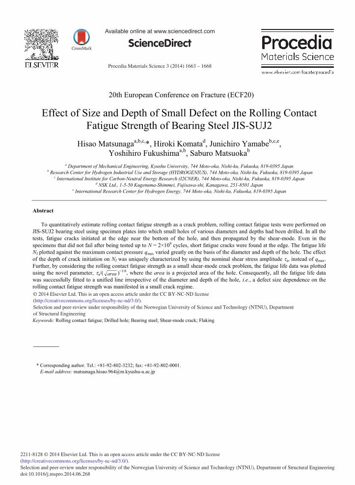
2.2. Rolling contact fatigue test and observation of fatigue cracks Figure 1 shows a schematic illustration of the thrust-bearing test machine. In the fatigue test, 9.525-mm steel
balls (JIS-SUJ2) were rolled around a circumference with a 38.5-mm diameter on one side of the specimen plate, while being subjected to a thrust load. Eleven 9.525-mm diameter steel balls (JIS-SUJ2) were used as the thrust balls. The rolling contact fatigue test was performed by rotating the steel balls in a lubricant (ISO-VG68) while applying a thrust load. The values of maximum contact pressure q max ranged from 2.5 to 3.6 GPa and the rate of rotation was 1000 min−1.
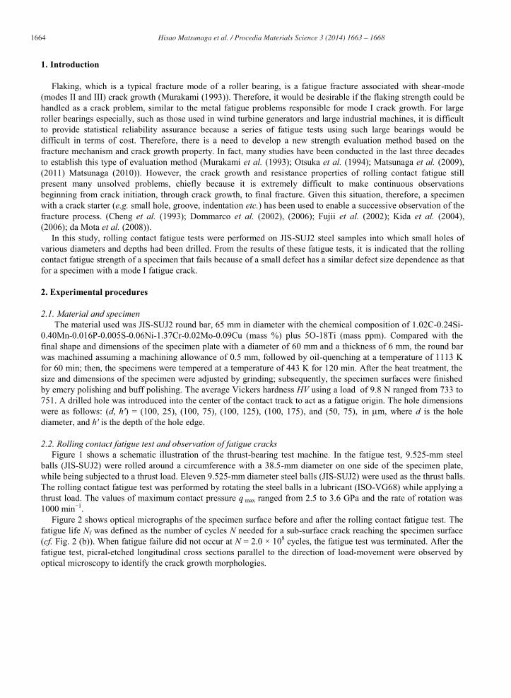
Figure 2 shows optical micrographs of the specimen surface before and after the rolling contact fatigue test. The fatigue life Nf was defined as the number of cycles N needed for a sub-surface crack reaching the specimen surface (cf. Fig. 2 (b)). When fatigue failure did not occur at N = 2.0 × 10⁸ cycles, the fatigue test was terminated. After the fatigue test, picral-etched longitudinal cross sections parallel to the direction of load-movement were observed by optical microscopy to identify the crack growth morphologies.
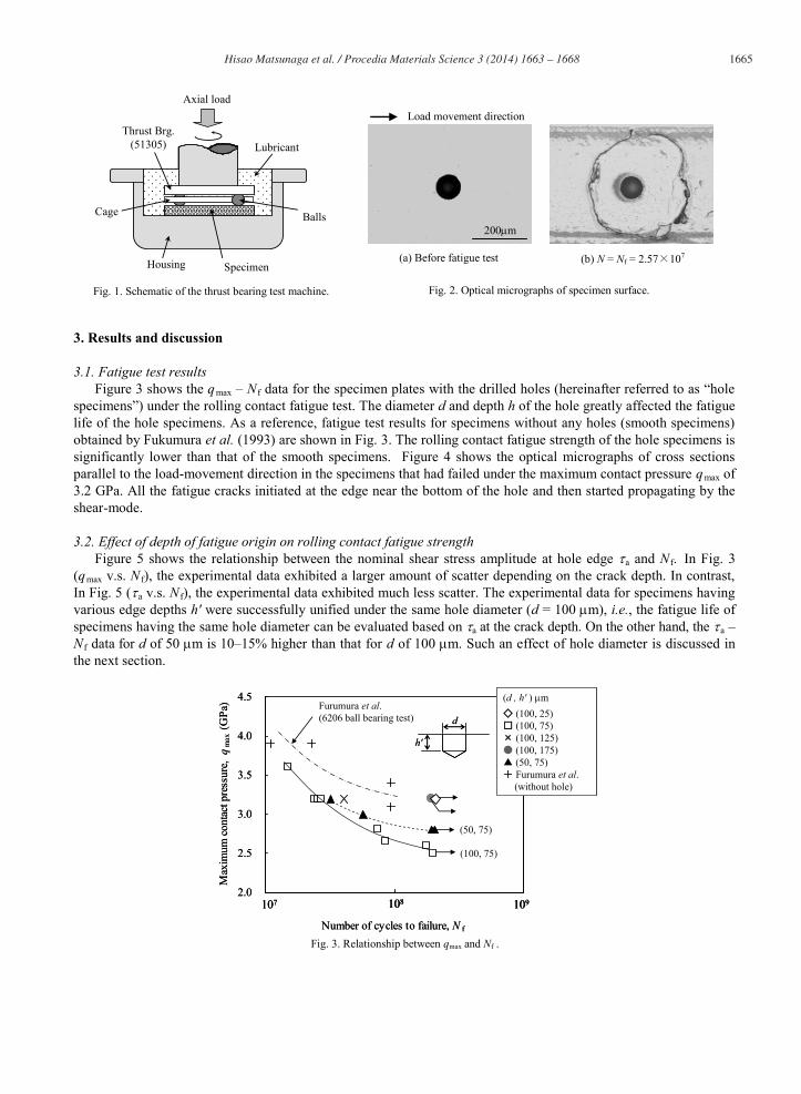
3.1. Fatigue test results Figure 3 shows the qmax – N f data for the specimen plates with the drilled holes (hereinafter referred to as “hole
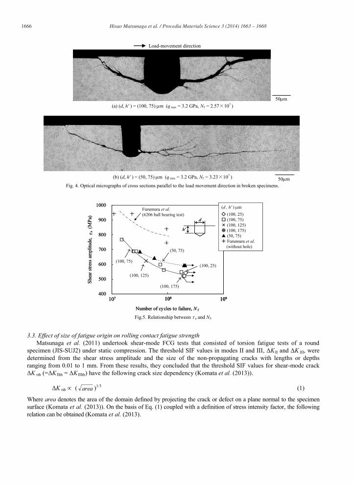
specimens”) under the rolling contact fatigue test. The diameter d and depth h of the hole greatly affected the fatigue life of the hole specimens. As a reference, fatigue test results for specimens without any holes (smooth specimens) obtained by Fukumura et al. (1993) are shown in Fig. 3. The rolling contact fatigue strength of the hole specimens is significantly lower than that of the smooth specimens. Figure 4 shows the optical micrographs of cross sections parallel to the load-movement direction in the specimens that had failed under the maximum contact pressure qmax of 3.2 GPa. All the fatigue cracks initiated at the edge near the bottom of the hole and then started propagating by the shear-mode.
3.2. Effect of depth of fatigue origin on rolling contact fatigue strength Figure 5 shows the relationship between the nominal shear stress amplitude at hole edge a and N f. In Fig. 3
(qmax v.s. N f), the experimental data exhibited a larger amount of scatter depending on the crack depth. In contrast, In Fig. 5 ( a v.s. N f), the experimental data exhibited much less scatter. The experimental data for specimens having various edge depths h' were successfully unified under the same hole diameter (d = 100 m), i.e., the fatigue life of specimens having the same hole diameter can be evaluated based on a at the crack depth. On the other hand, the a – N f data for d of 50 m is 10–15% higher than that for d of 100 m. Such an effect of hole diameter is discussed in the next section.
200 m
Fig. 2. Optical micrographs of specimen surface.
(a) Before fatigue test (b) N = Nf = 2.57 107
Load movement direction
SpecimenHousing
Axial load
LubricantThrust Brg.
(51305)
Cage Balls
Fig. 1. Schematic of the thrust bearing test machine.
3.3. Effect of size of fatigue origin on rolling contact fatigue strength Matsunaga et al. (2011) undertook shear-mode FCG tests that consisted of torsion fatigue tests of a round
specimen (JIS-SUJ2) under static compression. The threshold SIF values in modes II and III, ΔK II and ΔK III, were determined from the shear stress amplitude and the size of the non-propagating cracks with lengths or depths ranging from 0.01 to 1 mm. From these results, they concluded that the threshold SIF values for shear-mode crack ΔK τth (=ΔK IIth = ΔK IIIth) have the following crack size dependency (Komata et al. (2013))
ΔK τth ( area )1/3 (1)
Where area denotes the area of the domain defined by projecting the crack or defect on a plane normal to the specimen surface (Komata et al. (2013)). On the basis of Eq. (1) coupled with a definition of stress intensity factor, the following relation can be obtained (Komata et al. (2013).
Load-movement direction
(a) (d, h' ) = (100, 75) m (q max = 3.2 GPa, Nf = 2.57 107 )
50 m Fig. 4. Optical micrographs of cross sections parallel to the load movement direction in broken specimens.
50 m
(b) (d, h' ) = (50, 75) m (q max = 3.2 GPa, Nf = 3.23 107 )
Figure 6 shows optical micrographs of cross sections parallel to the load-movement direction in those specimens that did not fail when tested up to N = 2×10
8 cycles. In the unbroken specimens, fatigue cracks with a length of approximately 5 m were observed at the edge near the bottom of the hole. Thus, this study deals with all the test results as a small shear-mode fatigue crack problem regardless of whether or not the specimen fails.
Considering above experimental findings together with Eq. (2), the experimental results are summarized in Fig. 7 by using a / ( area )−1/6, instead of a in Fig. 5. Similar modified S-N diagram has also been used for the evaluation of the very high-cycle fatigue strength of high-strength steels that fail from non-metallic inclusions (Murakami et al. (1999), Furuya et al. (2004)). In Fig. 7, fatigue test results for the hole specimens were successfully fitted to a unified line, irrespective of the diameter and depth of the hole. This result implies that the rolling contact fatigue strength can be determined from the nominal shear stress amplitude a at the fatigue origin and the representative defect size such as area .
The present study focuses on a case whereby the shape of the fatigue origin (the edge of the drilled hole) is a circle. However, in a practical problem, small defects having various shapes exist in the material. The method to deal with such small defects having an arbitrary shape will be discussed in our forthcoming paper.
Fig.6. Optical micrographs of cross sections parallel to the load-movement direction in unbroken specimens.
(a) (d, h' ) = (100, 25) m (q max = 3.2 GPa, a = 542 MPa, N = 2.00 108 )
50 m 50 m
(b) (d, h' ) = (100, 75) m (q max = 2.5 GPa, a = 519 MPa, N = 2.00 108 )
This study undertook rolling contact fatigue tests on specimen plates (JIS-SUJ2) with small drilled holes of various diameters and depths. The conclusions can be summarized as follows: (1) The fatigue cracks originated from the edge near the bottom of the hole, and then, propagated by the shear-
modes (mode II and III). (2) The fatigue life Nf plotted against the maximum contact pressure qmax varied greatly with the diameter and
depth of the hole. In contrast, under the same hole diameter, Nf plotted against the nominal shear stress amplitude at crack initiation depth a was successfully fitted to a unified line irrespective of the depth of the hole.
(3) On the basis of a crack size dependence of the threshold stress intensity factor ranges in modes II and III (ΔK II and ΔK III), the fatigue life data was plotted using the novel parameter a/( area )−1/6, where the area is a projected area of the hole. Consequently, all the fatigue-life data could be successfully fitted to a unified line, irrespective of the diameter and depth of the hole.
Acknowledgements
This work was supported by the New Energy and Industrial Technology Development Organization (NEDO), Fundamental Research Project on Advanced Hydrogen Science (2006 to 2012) and Hydrogen Utilization Technology (2013 to 2018). The authors gratefully acknowledge the support of the International Institute for Carbon-Neutral Energy Research (I2CNER), established by the World Premier International (WPI) Research Center Initiative funded by the Ministry of Education, Culture, Sports, Science, and Technology (MEXT), Japan.
References
Cheng, W, Cheng, H. S., Keer, L. M., Ai, X., 1993. Surface Crack Initiation under Contact Fatigue: Experimental Observation and Contact Analysis. Transactions of the ASME, Journal of Tribology 115, 658–665.
da Mota, V. M. M. B., Moreira, P. M. G. P., Ferreira, L. A. A., 2008. A Study on the Effects of Dented Surfaces on Rolling Contact Fatigue. International Journal of Fatigue 30, 1997–2008.
Dommarco, R. C., Bastias, P. C., Hahn, G. T., Rubin, C. A., 2002. The Use of Artificial Defects in the 5-Ball-Rod Rolling Contact Fatigue Experiments. Wear 252, 430–437.
Dommarco, R. C., Bastias, P. C., Rubin, C. A., Hahn, G. T., 2006. The Influence of Material build up Around Artificial Defects on Rolling Contact Fatigue Life and Failure Mechanism. Wear 260, 1317–1323.
Fujii, Y., Maeda, K., 2002. Flaking Failure in Rolling Contact Fatigue Caused by Indentations on Mating Surface (I) Reproduction of Flaking Failure Accompanied by Cracks Extending Bi-Directionally Relative to the Load-Movement. Wear 252, 787–798.
Furumura, K., Murakami, Y., Abe, T., 1993. The Development of Bearing Steels for Long Life Rolling Bearings Under Clean Lubrication and Contaminated Lubrication. Proceeding of 4th International Symposium on Bearing Steels, Creative Use of Bearing Steels, ASTM STP 1195, 199–210.
Furuya, Y. and Matsuoka, S., 2004. Gigacycle fatigue properties of a modified-ausformed Si-Mn steel and effects of microstructure. Metallurgical and Materials Transaction A, 35, 1715–1723.
Kida, K., Yamazaki, T., Shibata, M., Oguma, N., Harada, H., 2004. Crack Initiation from Micro Surface Holes in Bearings under Rolling Contact Fatigue. Fatigue & Fracture of Engineering Materials & Structures 27, 481–493.
Kida, K., Yoshidome, K., Yamakawa, K., Harada, H., Oguma, N., 2006. Flaking Failures Originating from Microholes of Bearings under Rolling Contact Fatigue. Fatigue & Fracture of Engineering Materials & Structures 29, 1021–1030.
Komata, H., Yamabe, J., Matsunaga, H., Fukushima, Y., Matsuoka, S., 2013. Effect of Size and Depth of Small Defect on the Rolling Contact Fatigue Strength of a Bearing Steel SUJ2. Transactions of the Japan Society of Mechanical Engineers A 79, 961–975.
Matsunaga, H., Muramoto, S., Shomura, N., Endo, M., 2009. Shear Mode Growth and Threshold of Small Fatigue Cracks in SUJ2 Bearing Steel. Journal of the Society of Materials Science, Japan 58, 773–780.
Matsunaga, H., Shomura, N., Muramoto, S., Endo, M., 2011. Shear Mode Threshold for a Small Fatigue Crack in a Bearing Steel. Fatigue & Fracture of Engineering Materials & Structures 34, 72–82.
Murakami, Y., 1993. Application of Fracture Mechanics to Tribology Problems. Transactions of the Japan Society of Mechanical Engineers A 59, 283–290.
Murakami, Y., Takada, M. and Toriyama, T., 1999. Super-long life tension-compression fatigue properties of quenched and tempered 0.46% carbon steel. International Journal of Fatigue, 16, 661–667.
Otsuka, A., Sugawara, H., Shomura, M., Aoyama, M., Yoo, S.K., Shidata, M., 1994. Mechanism of Rolling Contact Fatigue and Mode II Fatigue Crack Growth–A Proposal on a Mode II Fatigue Crack Growth Test Method. Journal of the Society of Materials Science, Japan 43, 55–61.