139 EFFECT OF SOIL-PILE INTERACTION ON FIXED OFFSHORE PLATFORM BEHAVIOUR K.S. Arun Post Graduate Student, Department of Civil Engineering, National Institute of Technology, Tiruchirappalli–620 015, India. E-mail: [email protected]K. Muthukkumaran Assistant Professor, Department of Civil Engineering, National Institute of Technology, Tiruchirappalli–620 015, India. E-mail: [email protected]ABSTRACT: The present investigation is to perform a static wave analysis on a typical fixed offshore platform for extreme environmental conditions, considering multilayer soil block and to study the effects of the combined lateral and vertical loads on pile group foundation. The lateral forces considered are wave forces and forces due to ocean currents. The finite element model of the structure including the soil block is modeled in a finite element package—FLAC 3D and is employed herein to determine the soil structure interaction. The platform has got four legs and each leg of the platform is supported on a pile group consisting of four piles. Graphs are plotted with lateral displacement, shear force and bending moment versus depth of pile, for the piles in the pile group. From these graphs, the maximum values for lateral displacement, shear force and bending moment are compared for the piles in the group. 1. INTRODUCTION 1.1 Soil-Structure Interaction Soil-Structure Interaction is the mechanism that governs the pile response behaviour and ultimate capacity of the structure to applied loads. Piles have been extensively used for supporting axial loads and lateral loads for offshore structures. Among the forces produced by the environmental factors, wave forces and forces due to ocean currents are the forces which contribute the most to the total lateral loads experienced by an offshore structure. The response to environmental loads is strongly affected by the soil structure (pile) interaction. The governing criterion in designing pile foundations to resist lateral loads in most cases is the maximum deflection and moment of the piles rather than its ultimate capacity. 1.2 Fixed Offshore Platform In the study of response of fixed offshore structures, pile foundations have got much importance. Wave forces and force due to ocean currents are calculated and applied as lateral loads in the present study. And structural load is also applied which includes all the loads coming over the deck. Multilayered soil block is considered in this study as in the actual case. To provide a more accurate and effective design for offshore pile foundation systems under axial structural loads and lateral wave loads, a finite element model which is modelled in FLAC 3D is employed herein to determine the soil structure interaction. 1.3 Literature Review J.A. Eicher, H. Guan, D.S. Jeng (2003), in their study, the deformation of and stresses in a single offshore concrete pile under combined structural and wave loading is analysed by the finite element method. Yasser E. Mostafa, M. Hesham El Naggar (2004), has investigated the response of fixed offshore platforms supported by clusters of piles. The soil resistance to the pile movement is modelled using dynamic p–y curves and t–z curves to account for soil nonlinearity and energy dissipation through radiation damping. The load transfer curves for a single pile have been modified to account for the group effect. Yasser E. Mostafa, M. Hesham El Naggar (2006), has examined the effect of seabed instability on a fixed offshore structure in their study. Dynamic p–y curves, dynamic t–z curves and q–z curves have been used to simulate the soil resistance in the lateral and axial directions. The effect of different parameters that influence the response of offshore structures to seabed instability is evaluated. As fixed jacket platforms are the most common type of platform used. It is, thus, in industrial and commercial interest that these platforms have a long life without succumbing to the harsh environment in which they have to perform. Fixed Jacket platforms are very accident prone. Accidents have occurred in the past in all the four stages; during transportation, installation, operation and removal. The probability of accidents can be reduced by proper design and analysis of the structure. IGC 2009, Guntur, INDIA
Transcript
Effect of Soil-Pile Interaction on Fixed Offshore Platform Behaviour
139
EFFECT OF SOIL-PILE INTERACTION ON FIXED OFFSHORE PLATFORM BEHAVIOUR
K.S. Arun Post Graduate Student, Department of Civil Engineering, National Institute of Technology, Tiruchirappalli–620 015, India. E-mail: [email protected] K. Muthukkumaran Assistant Professor, Department of Civil Engineering, National Institute of Technology, Tiruchirappalli–620 015, India. E-mail: [email protected]
ABSTRACT: The present investigation is to perform a static wave analysis on a typical fixed offshore platform for extreme environmental conditions, considering multilayer soil block and to study the effects of the combined lateral and vertical loads on pile group foundation. The lateral forces considered are wave forces and forces due to ocean currents. The finite element model of the structure including the soil block is modeled in a finite element package—FLAC 3D and is employed herein to determine the soil structure interaction. The platform has got four legs and each leg of the platform is supported on a pile group consisting of four piles. Graphs are plotted with lateral displacement, shear force and bending moment versus depth of pile, for the piles in the pile group. From these graphs, the maximum values for lateral displacement, shear force and bending moment are compared for the piles in the group. 1. INTRODUCTION
1.1 Soil-Structure Interaction
Soil-Structure Interaction is the mechanism that governs the pile response behaviour and ultimate capacity of the structure to applied loads. Piles have been extensively used for supporting axial loads and lateral loads for offshore structures. Among the forces produced by the environmental factors, wave forces and forces due to ocean currents are the forces which contribute the most to the total lateral loads experienced by an offshore structure. The response to environmental loads is strongly affected by the soil structure (pile) interaction. The governing criterion in designing pile foundations to resist lateral loads in most cases is the maximum deflection and moment of the piles rather than its ultimate capacity.
1.2 Fixed Offshore Platform
In the study of response of fixed offshore structures, pile foundations have got much importance. Wave forces and force due to ocean currents are calculated and applied as lateral loads in the present study. And structural load is also applied which includes all the loads coming over the deck. Multilayered soil block is considered in this study as in the actual case. To provide a more accurate and effective design for offshore pile foundation systems under axial structural loads and lateral wave loads, a finite element model which is modelled in FLAC 3D is employed herein to determine the soil structure interaction.
1.3 Literature Review
J.A. Eicher, H. Guan, D.S. Jeng (2003), in their study, the deformation of and stresses in a single offshore concrete pile under combined structural and wave loading is analysed by the finite element method. Yasser E. Mostafa, M. Hesham El Naggar (2004), has investigated the response of fixed offshore platforms supported by clusters of piles. The soil resistance to the pile movement is modelled using dynamic p–y curves and t–z curves to account for soil nonlinearity and energy dissipation through radiation damping. The load transfer curves for a single pile have been modified to account for the group effect. Yasser E. Mostafa, M. Hesham El Naggar (2006), has examined the effect of seabed instability on a fixed offshore structure in their study. Dynamic p–y curves, dynamic t–z curves and q–z curves have been used to simulate the soil resistance in the lateral and axial directions. The effect of different parameters that influence the response of offshore structures to seabed instability is evaluated.
As fixed jacket platforms are the most common type of platform used. It is, thus, in industrial and commercial interest that these platforms have a long life without succumbing to the harsh environment in which they have to perform. Fixed Jacket platforms are very accident prone. Accidents have occurred in the past in all the four stages; during transportation, installation, operation and removal. The probability of accidents can be reduced by proper design and analysis of the structure.
IGC 2009, Guntur, INDIA
Effect of Soil-Pile Interaction on Fixed Offshore Platform Behaviour
140
2. PLATFORM DESCRIPTION
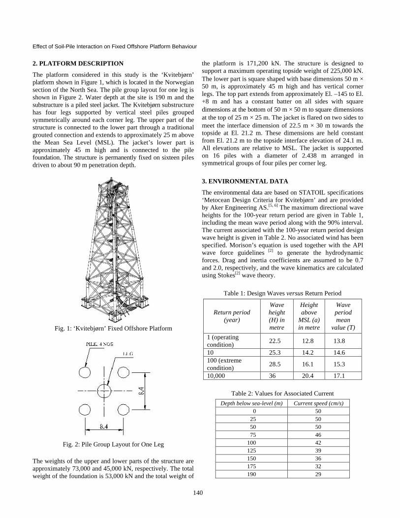
The platform considered in this study is the ‘Kvitebjørn’ platform shown in Figure 1, which is located in the Norwegian section of the North Sea. The pile group layout for one leg is shown in Figure 2. Water depth at the site is 190 m and the substructure is a piled steel jacket. The Kvitebjørn substructure has four legs supported by vertical steel piles grouped symmetrically around each corner leg. The upper part of the structure is connected to the lower part through a traditional grouted connection and extends to approximately 25 m above the Mean Sea Level (MSL). The jacket’s lower part is approximately 45 m high and is connected to the pile foundation. The structure is permanently fixed on sixteen piles driven to about 90 m penetration depth.
Fig. 1: ‘Kvitebjørn’ Fixed Offshore Platform
Fig. 2: Pile Group Layout for One Leg
The weights of the upper and lower parts of the structure are approximately 73,000 and 45,000 kN, respectively. The total weight of the foundation is 53,000 kN and the total weight of
the platform is 171,200 kN. The structure is designed to support a maximum operating topside weight of 225,000 kN. The lower part is square shaped with base dimensions 50 m × 50 m, is approximately 45 m high and has vertical corner legs. The top part extends from approximately El. –145 to El. +8 m and has a constant batter on all sides with square dimensions at the bottom of 50 m × 50 m to square dimensions at the top of 25 m × 25 m. The jacket is flared on two sides to meet the interface dimension of 22.5 m × 30 m towards the topside at El. 21.2 m. These dimensions are held constant from El. 21.2 m to the topside interface elevation of 24.1 m. All elevations are relative to MSL. The jacket is supported on 16 piles with a diameter of 2.438 m arranged in symmetrical groups of four piles per corner leg.
3. ENVIRONMENTAL DATA
The environmental data are based on STATOIL specifications ‘Metocean Design Criteria for Kvitebjørn’ and are provided by Aker Engineering AS.[5, 6] The maximum directional wave heights for the 100-year return period are given in Table 1, including the mean wave period along with the 90% interval. The current associated with the 100-year return period design wave height is given in Table 2. No associated wind has been specified. Morison’s equation is used together with the API wave force guidelines [2] to generate the hydrodynamic forces. Drag and inertia coefficients are assumed to be 0.7 and 2.0, respectively, and the wave kinematics are calculated using Stokes[2] wave theory.
Table 2: Values for Associated Current Depth below sea-level (m) Current speed (cm/s)
0 50 25 50 50 50 75 46
100 42 125 39 150 36 175 32 190 29
Effect of Soil-Pile Interaction on Fixed Offshore Platform Behaviour
141
3.1 Procedure Followed to Find Wave Loads
From the environmental data for extreme environmental conditions, and using the limits of validity for selected wave theory (Le Mehaute)[4], it is found out that the region comes in the area of deep water waves and Stokes wave theory, which has been used for the calculation of water particle velocity and acceleration (wave kinematics). Morison’s[2] equation is used together with the API[2] wave force guidelines to generate the wave forces. Since the currents are associated with the waves, due consideration should be given to the possible superposition of current and waves. So the current velocity should be added vectorially to the wave particle velocity before the total force is computed using Morison’s equation. Hence, the total lateral loads due to waves and current associated with the waves are calculated at different heights of the platform from the seabed level to the mean sea level.
4. SOIL PROFILE
The properties of the multilayered soil block considered in this study are formulated from the known cu (undrained shear strength) value and the type of soil layer. The Poisson’s ratio is considered as 0.25 for sand and 0.35 for clay. From the cu value, Poisson’s ratio and the type of soil layers, the other properties which has to be given as inputs for FLAC 3D are formulated and is shown in Table 3. These properties include Modulus of Elasticity (E) in kPa, Angle of internal friction (F ) in degrees, cohesion (c) in kPa and shear strength in kPa.
Table 3: Properties of the Multilayered Soil Block
Soil layer data (downwards from seabed) FLAC 3D inputs
Sl. No.
Depth (m) Type of Soil E in
kPa F o C in
kPa
Shear Strength in kPa
1. 7.5 Very soft to silty sandy clay
3000 0 15 15
2. 24.5 Sandy, clayey silt 40000 0 80 80
3. 15 Very stiff to hard silty clay
180000 0 150 150
4. 5 Very dense fine sand 100000 35 _ 300
5. 10 Very stiff to hard clay 435000 0 290 290
6. 15 Very stiff to hard clay 277500 0 185 185
7. 8 Very stiff to hard clay 292500 0 195 195
5. MODELLING OF THE STRUCTURE IN FLAC 3D
Multilayered soil block is modelled using brick mesh shape elements which is having 8 reference points or nodes. Piles and the platform legs which are assigned as pile and beam members respectively, in FLAC 3D, are modelled as two noded structural element segments. Horizontal members and bracings are also modelled as beam members. Piles interact with the grid via shear and normal coupling springs. The piles in each group are fixed to a rigid cap which is modelled as pile cap plate using shell elements, and the deck plate also are modelled using shells which is represented by three-noded, flat triangular elements. The stiffness matrix of the beam or pile finite element includes all six degrees of freedom at each node to represent axial, shear and bending action within a beam structure. The 3D view of the model generated is shown in Figure 3.
Fig. 3: 3D View of the Model Generated Using FLAC 3D
6. APPLICATION OF LOADS
Structural load on the deck = 2,30,000 kN. It is assumed that the wave load acts in the x-direction as mentioned in the 3D model, and is applied in the same direction. Structural load is applied as pressure over the deck plate. Total lateral load (F) caused by waves and associated current is applied along x-direction (as in the 3D model) at regular intervals along the platform downwards from MSL to the seabed level, in the 2 leg members. The application of loads in elevation and plan is as shown in Figures 4 & 5 respectively. Legends followed are as shown in Figure 5.
Effect of Soil-Pile Interaction on Fixed Offshore Platform Behaviour
142
Fig. 4: Application of Wave Load in Elevation
Fig. 5: Application of Wave Load in Plan (legends shown)
7. RESULTS AND CONCLUSIONS
For the response study, the piles L1P2, L1P3, L2P2 and L2P3 are chosen, which are the front and rear piles of leg1 and leg2. According to the direction of loading (x-direction as shown in Figure 6), the front and rear piles of legs are mentioned here. These four piles in a row in x-direction are chosen for the response study, since the other piles will also behave
symmetrically due to the same direction of lateral loading. Maximum lateral displacement at seabed surface among all the piles has occurred in the rear piles of leg1 and leg2.
Fig. 6: Lateral Displacement vs. Depth of Pile
7.1 Comparison—Rear Piles of Leg1 and Leg2
While comparing the rear piles of leg1 and leg2, it can be seen that the lateral displacement (Fig. 7) produced is more in the rear pile of leg2 (L2P3) than that of leg1 (L1P3). The values of lateral displacement of piles at pile top are L1P3-74.05 mm & L2P3-82.1 mm respectively. The values of lateral displacement of piles at seabed level are L1P3-56.8 mm & L2P3-61.8 mm respectively. In case of negative bending moment about y-axis (Fig. 8), it can be seen that the maximum bending moment is more in L2P3 than L1P3. The values of maximum bending moments are L1P3-2.84 × 10⁶ Nm & L2P3-6.6 × 10⁶ Nm respectively. And in case of shear force (Fig. 9), maximum negative shear force at seabed level is produced more in L2P3 than L1P3. The values of negative shear force at seabed level are L1P3-0.33 × 10⁶N & L2P3-1.2 × 10⁶N respectively.
Fig. 7: Lateral Displacement vs. Depth of Pile
Effect of Soil-Pile Interaction on Fixed Offshore Platform Behaviour
143
Fig. 8: Bending Moment vs. Depth of Pile
Fig. 9: Shear Force vs. Depth of Pile
7.2 Comparison—Front and Rear Piles of Leg2
Comparing the front pile-L2P2 and rear pile-L2P3 of leg2, it can be seen that the lateral displacement (Fig. 7) produced is more in the rear pile than front pile. The values of lateral displacement at top nodes are L2P2-49.5 mm & L2P3-61.75 mm respectively. In case of shear force (Fig. 9), negative shear force at seabed level is produced more in the top node of rear pile than that of front pile of leg2. The values of maximum negative shear force at seabed level are L2P2-0.34 × 10⁶ N & L2P3-1.2 × 10⁶ N respectively. In case of bending moment (Fig. 8), it can be seen that the maximum bending moment is more in L2P3 than L2P2. The values of maximum bending moments are L2P2-5.5 × 10⁶ Nm at 4 m depth from seabed & L2P3-6.6 × 10⁶ Nm at 16 m depth from seabed respectively. The difference in bending moment is 1.1 × 10⁶ N.
REFERENCES
[1] Mostafa, Y.E. and El Naggar, M.H. (2006). “Effect of Seabed Instability on Fixed Offshore Platforms”, Soil Dynamics and Earthquake Engineering, 26, 1127–1142.
[2] Recommended Practice for Planning, “Designing and Constructing Fixed Offshore Platforms—Working Stress Design”, American Petroleum Institute Recommended Practice 2A-WSD. 21st ed. Washington, DC; 2005.
[3] Mostafa, Y.E and El Naggar, M.H. (2004). “Response of Fixed Offshore Platforms to Wave and Current Loading Including Soil–Structure Interaction”, Soil Dynamics and Earthquake Engineering, 24, 357–368.
[4] Le Mehaute, B. (1969). An Introduction to Hydrodynamics and Water Waves, Vol. 2: Water Wave Theories, Essa Technical Report ERL 118-POL-3-2, U.S. Dept. of Commerce, Environmental Science Services Administration, Pacific Oceanographic Laboratories, Miami, FL.


![[P. Le Tirant] Design Guides for Offshore Structures Offshore Pile Design](https://static.documents.pub/doc/80x56/563dbb49550346aa9aabde71/p-le-tirant-design-guides-for-offshore-structures-offshore-pile-design.jpg)


