Memoirs of the Faculty of Engineering, Kyushu University, Vol.68, No.1, March 2008 Effect of Ultrasonic Vibration on Micro Grooving by Osamu OHNISHI * , Hiromichi ONIKURA ** , Seung-Ki MIN *** Muhammad Aziz † and Sho TSURUOKA † (Received November 5, 2007) Abstract This paper deals with the micro cutting method to fulfill the current demand for higher precision and efficiency in micro machining. In this work, a micro end mill with a diameter of 20 μm is fabricated and its performance is evaluated in grooving under the condition of with or without ultrasonic vibration assistance. Here, the machining characteristic is clarified and further its machining mechanism is also considered. Experimental results showed that micro grooving conducted with the assistance of ultrasonic vibration proven to be an effective method for burr removal. Keywords: Micro end mill, Micro grooving, Ultrasonic vibration, Machining accuracy, Burr, Surface roughness 1. Introduction Recently, as the need for high precision and functionality in products manufacturing increasing, the demand for higher precision in micro machining for manufactured parts and products also rises very quickly. In the world of micro machining technology, there are some methods available, such as conventional cutting, grinding, electric discharge machining, laser machining, LIGA process, etching etc. Here, with the consideration of higher machining capability in terms of high precision and efficiency, conventional cutting method is picked up. Unfortunately, it is very difficult to apply a usual conventional cutting method to a micro machining as there are some problems such as large cutting force, etc. On the other hand, regarding an ultrasonic vibration assisted cutting, there are some research results which show the effect of ultrasonic vibration is effective in the reduction of cutting force, further, improvement of tool life and machining accuracy 1)-5) . * ** *** † Assistant Professor, Department of Intelligent Machinery and Systems Professor, Department of Intelligent Machinery and Systems Graduate Student, Department of Intelligent Machinery and Systems (Now, Senior Engineer of Samsung Electro-Mechanics Co., Ltd.) Graduate Student, Department of Intelligent Machinery and Systems
Transcript
Memoirs of the Faculty of Engineering, Kyushu University, Vol.68, No.1, March 2008
This paper deals with the micro cutting method to fulfill the current demand for higher precision and efficiency in micro machining. In this work, a micro end mill with a diameter of 20 µm is fabricated and its performance is evaluated in grooving under the condition of with or without ultrasonic vibration assistance. Here, the machining characteristic is clarified and further its machining mechanism is also considered. Experimental results showed that micro grooving conducted with the assistance of ultrasonic vibration proven to be an effective method for burr removal.
1. Introduction Recently, as the need for high precision and functionality in products manufacturing increasing, the demand for higher precision in micro machining for manufactured parts and products also rises very quickly. In the world of micro machining technology, there are some methods available, such as conventional cutting, grinding, electric discharge machining, laser machining, LIGA process, etching etc. Here, with the consideration of higher machining capability in terms of high precision and efficiency, conventional cutting method is picked up. Unfortunately, it is very difficult to apply a usual conventional cutting method to a micro machining as there are some problems such as large cutting force, etc. On the other hand, regarding an ultrasonic vibration assisted cutting, there are some research results which show the effect of ultrasonic vibration is effective in the reduction of cutting force, further, improvement of tool life and machining accuracy1)-5).
*
**
***
†
Assistant Professor, Department of Intelligent Machinery and Systems Professor, Department of Intelligent Machinery and Systems Graduate Student, Department of Intelligent Machinery and Systems (Now, Senior Engineer of Samsung Electro-Mechanics Co., Ltd.) Graduate Student, Department of Intelligent Machinery and Systems
2 O. OHNISHI, H. ONIKURA, S. MIN, M. Aziz and S. TSURUOKA
Based on those results, in this paper, ultrasonic vibration is evaluated to overcome the problem owned by a conventional cutting method with the aim to realize a micro end milling with higher precision and efficiency. Here, groovings with or without ultrasonic vibration are carried out and their machining characteristics are clarified. And a consideration upon the machining mechanism occurs during grooving is also discussed.
2. Experiment Method and Condition In this research, after finishing the fabrication process of micro end mill, the grooving test is performed. Experiment is conducted on a vertical machining center (MSA40-0, Makino Seiki Co., Ltd.). Figure 1 shows the structure of experiment devices used for fabrication of micro end mill. During the fabrication of micro end mill, diamond wheel is clamped on the main spindle and, on the other hand, the tool blank of micro end mill (cemented carbide) is installed on the sub-spindle fixed on the rotary table, which is fixed on the table of machining center. Before the fabrication of micro end mill with a diameter of 20 µm, dressing and truing for peripheral and end faces of diamond wheel is performed by using GC rotary dresser installed on machining center table. The material of tool blank of micro end mill is ultra-fine grained cemented carbide having WC particle with a diameter of 90 nm. Based on the experiment conducted with 5 types of tool shape, as shown in Fig.2(a) – (e), tool
Fig.1 Experiment devices used for micro end mill fabrication.
(a) Type a (b) Type b
(c) Type c (d) Type d (d) Type e
Fig.2 Tool shapes of micro end mills.
Effect of Ultrasonic Vibration on Micro Grooving 3
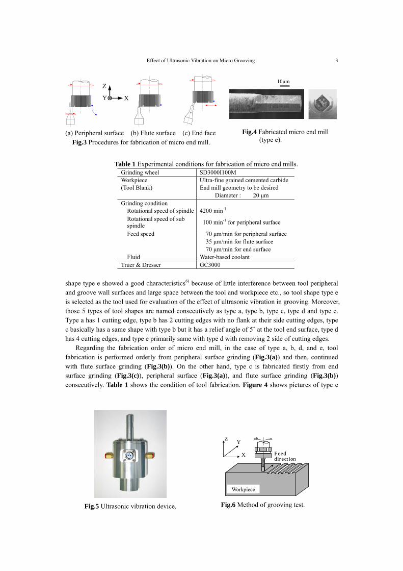
shape type e showed a good characteristics6) because of little interference between tool peripheral and groove wall surfaces and large space between the tool and workpiece etc., so tool shape type e is selected as the tool used for evaluation of the effect of ultrasonic vibration in grooving. Moreover, those 5 types of tool shapes are named consecutively as type a, type b, type c, type d and type e. Type a has 1 cutting edge, type b has 2 cutting edges with no flank at their side cutting edges, type c basically has a same shape with type b but it has a relief angle of 5˚ at the tool end surface, type d has 4 cutting edges, and type e primarily same with type d with removing 2 side of cutting edges. Regarding the fabrication order of micro end mill, in the case of type a, b, d, and e, tool fabrication is performed orderly from peripheral surface grinding (Fig.3(a)) and then, continued with flute surface grinding (Fig.3(b)). On the other hand, type c is fabricated firstly from end surface grinding (Fig.3(c)), peripheral surface (Fig.3(a)), and flute surface grinding (Fig.3(b)) consecutively. Table 1 shows the condition of tool fabrication. Figure 4 shows pictures of type e
(a) Peripheral surface (b) Flute surface (c) End face Fig.3 Procedures for fabrication of micro end mill.
10µm
Workpiec
Feed direction
Y
X
Z
Fig.6 Method of grooving test.
Fig.4 Fabricated micro end mill (type e).
Table 1 Experimental conditions for fabrication of micro end mills.
Grinding wheel SD3000I100M Workpiece Ultra-fine grained cemented carbide (Tool Blank) End mill geometry to be desired Diameter : 20 µm Grinding condition Rotational speed of spindle 4200 min-1 Rotational speed of sub spindle 100 min-1 for peripheral surface
Feed speed 70 µm/min for peripheral surface 35 µm/min for flute surface 70 µm/min for end surface Fluid Water-based coolant Truer & Dresser GC3000
Fig.5 Ultrasonic vibration device.
Workpiece
4 O. OHNISHI, H. ONIKURA, S. MIN, M. Aziz and S. TSURUOKA
taken with scanning electron microscope. During this grooving test, fabricated micro end mill is clamped on the main spindle of machining center. On the other hand, grooving workpiece, which is duralumin (A2017) plate, is fixed on an ultrasonic vibration device (Fig.5) which is, in turn, installed on machining center table. By using ultrasonic vibration device, a vibration with a single amplitude of 0.5 µm in Z axis direction and a frequency of 58 kHz could be generated on to the workpiece. For the grooving method, as shown in Fig.6, after giving a cutting depth of 3 µm to the end mill, grooving of 10 mm in length for one grooving line is carried out. Grooving condition is shown in Table 2.
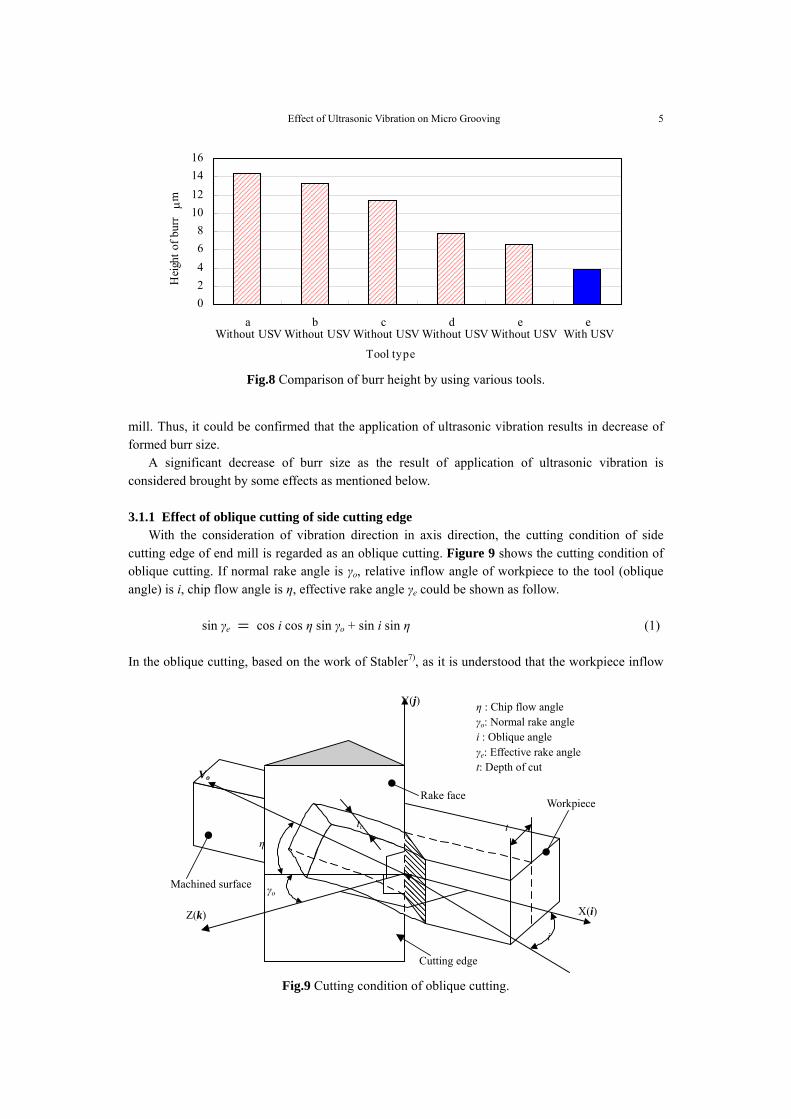
3. Experiment Results and Discussion 3.1 Burr Figure 7 shows the groove machined with end mill type e. As it could be observed from the picture, it is understood that ultrasonic vibration causes a significant decrease of burr size. Moreover, Fig.8 shows the burr height from grooving test conducted with all types of micro end mill. After measuring the length of parts corresponding to the burr height which is measured from the pictures taken in inclined direction, it is then, converted to burr height in vertical direction using trigonometric relationship. Type e shows the smallest burr height compared with other types of end
a 1 2 0.476 Without b 2 4 0.476 Without c 2 4 0.476 Without d 4 8 0.476 Without e 2 4 0.476 Without
Feed per tooth
e 2 4 0.476 With (58kHz, amp.0.5µm)
Fluid Water-based coolant
(a) Without ultrasonic vibration (b) With ultrasonic vibration
Fig.7 Micro grooves by using micro end mill type e.
20µm
Effect of Ultrasonic Vibration on Micro Grooving 5
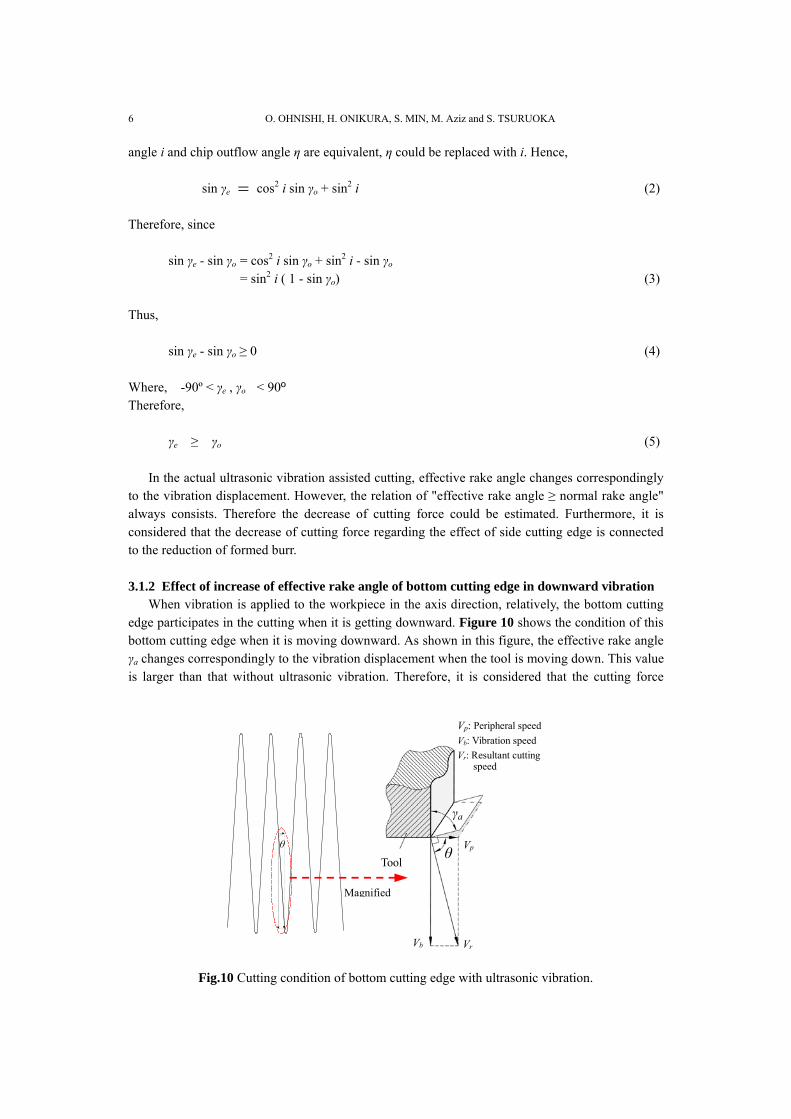
mill. Thus, it could be confirmed that the application of ultrasonic vibration results in decrease of formed burr size. A significant decrease of burr size as the result of application of ultrasonic vibration is considered brought by some effects as mentioned below. 3.1.1 Effect of oblique cutting of side cutting edge With the consideration of vibration direction in axis direction, the cutting condition of side cutting edge of end mill is regarded as an oblique cutting. Figure 9 shows the cutting condition of oblique cutting. If normal rake angle is γo, relative inflow angle of workpiece to the tool (oblique angle) is i, chip flow angle is η, effective rake angle γe could be shown as follow. sin γe = cos i cos η sin γo + sin i sin η (1) In the oblique cutting, based on the work of Stabler7), as it is understood that the workpiece inflow
Without USV Without USV Without USV Without USV Without USV With USV
Fig.8 Comparison of burr height by using various tools.
����������
Cutting edge
γo
Rake face
Z(k)
Y(j)
X(i)
i
η : Chip flow angle γo: Normal rake angle i : Oblique angle γe: Effective rake angle t: Depth of cut
η t
Vo
tc
Workpiece
Machined surface
Fig.9 Cutting condition of oblique cutting.
6 O. OHNISHI, H. ONIKURA, S. MIN, M. Aziz and S. TSURUOKA
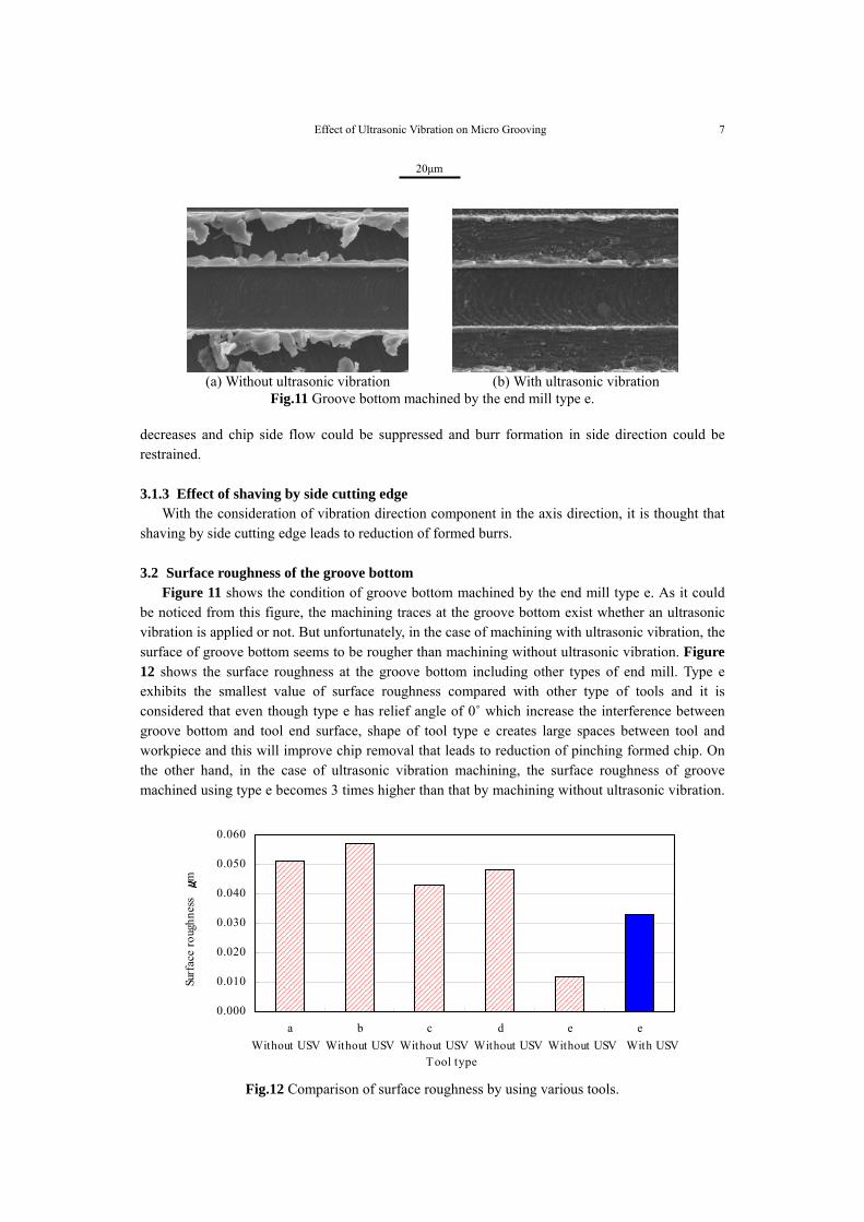
angle i and chip outflow angle η are equivalent, η could be replaced with i. Hence, sin γe = cos2 i sin γo + sin2 i (2) Therefore, since sin γe - sin γo = cos2 i sin γo + sin2 i - sin γo = sin2 i ( 1 - sin γo) (3) Thus, sin γe - sin γo ≥ 0 (4) Where, -90º < γe , γo < 90º Therefore, γe ≥ γo (5) In the actual ultrasonic vibration assisted cutting, effective rake angle changes correspondingly to the vibration displacement. However, the relation of "effective rake angle ≥ normal rake angle" always consists. Therefore the decrease of cutting force could be estimated. Furthermore, it is considered that the decrease of cutting force regarding the effect of side cutting edge is connected to the reduction of formed burr. 3.1.2 Effect of increase of effective rake angle of bottom cutting edge in downward vibration When vibration is applied to the workpiece in the axis direction, relatively, the bottom cutting edge participates in the cutting when it is getting downward. Figure 10 shows the condition of this bottom cutting edge when it is moving downward. As shown in this figure, the effective rake angle γa changes correspondingly to the vibration displacement when the tool is moving down. This value is larger than that without ultrasonic vibration. Therefore, it is considered that the cutting force
Fig.10 Cutting condition of bottom cutting edge with ultrasonic vibration.
Effect of Ultrasonic Vibration on Micro Grooving 7
decreases and chip side flow could be suppressed and burr formation in side direction could be restrained. 3.1.3 Effect of shaving by side cutting edge With the consideration of vibration direction component in the axis direction, it is thought that shaving by side cutting edge leads to reduction of formed burrs. 3.2 Surface roughness of the groove bottom Figure 11 shows the condition of groove bottom machined by the end mill type e. As it could be noticed from this figure, the machining traces at the groove bottom exist whether an ultrasonic vibration is applied or not. But unfortunately, in the case of machining with ultrasonic vibration, the surface of groove bottom seems to be rougher than machining without ultrasonic vibration. Figure 12 shows the surface roughness at the groove bottom including other types of end mill. Type e exhibits the smallest value of surface roughness compared with other type of tools and it is considered that even though type e has relief angle of 0˚ which increase the interference between groove bottom and tool end surface, shape of tool type e creates large spaces between tool and workpiece and this will improve chip removal that leads to reduction of pinching formed chip. On the other hand, in the case of ultrasonic vibration machining, the surface roughness of groove machined using type e becomes 3 times higher than that by machining without ultrasonic vibration.
(a) Without ultrasonic vibration (b) With ultrasonic vibration
Fig.11 Groove bottom machined by the end mill type e.
Without USV Without USV Without USV Without USV Without USV With USV
Fig.12 Comparison of surface roughness by using various tools.
8 O. OHNISHI, H. ONIKURA, S. MIN, M. Aziz and S. TSURUOKA
It is thought that in the case of grooving with application of ultrasonic vibration in axis direction, especially during the downward vibration, the interference between bottom cutting edge flank surface and workpiece brought a defective influence to the surface. 3.3 Tool wear Figure 13 shows the condition of end mill type e after grooving with ultrasonic vibration. From the figure, a significant tool wear could be observed and it is considered that this phenomenon is caused by the effect of long abrasion distance and also a severe interference with the workpiece.
4. Conclusion This paper deals with the fabrication of micro end mills with prescribed tool shapes having a diameter of 20 µm and a further clarification of ultrasonic vibration effect after evaluating their machining characteristics under machining of with and without ultrasonic vibration. The experiment results could be summarized as follow: • In the case of ultrasonic vibration application, there are some factors leading to an effective burr
removal such as an oblique cutting of side cutting edge, an increase of effective rake angle of the bottom cutting edge during downward vibration and shaving of formed burrs.
• When an ultrasonic vibration is applied during machining, the interference between tool and groove bottom surface occurs and brings a defective influence to the surface properties of groove bottom.
• In machining with ultrasonic vibration, a larger tool wear appears as the result of long abrasion distance and also a severe interference with the workpiece.
Regarding some factors participating in surface properties of groove bottom, the idea of creating a relief angle at the end mill is considered as a method to overcome it. Moreover, the idea of tool coating is measured to solve the current problem concerning the tool wear. Lastly, because it is considered that the most important point requested in micro grooving is “burr free machining”, the application of ultrasonic vibration during grooving is recognized as an effective method for its realization in spite of no measurement of cutting force.
Acknowledgements The observation and picturing of fabricated tools and machined grooves were performed by the scanning electron microscope equipped in the Center of Advanced Instrumental Analysis, Kyushu University.
References
1) J. Kumabe, Vibration cutting -fundamentals and applications-, Jikkyo Shuppan, (1979), [in Japanese].
Fig.13 Tool wear after grooving with ultrasonic vibration (Type e).
5µm
Effect of Ultrasonic Vibration on Micro Grooving 9
2) J. Kumabe, T. Sabuzawa and T. Saotome, Study on the Precision Drilling of Wood (3rd Report), Trans. Japan Soc. Prec. Eng., Vol.43, No.6, pp.683-689 (1977), [in Japanese].
3) H. Weber,J. Herberger,R. Pilz, Turning of Machinable Glass Ceramics with an Ultrasonically Vibrated Tool, Annals of the CIRP, Vol.33, No.1, pp.85-87 (1984).
4) H. Takeyama, N. Iijima, Machinability of Glassfiber Reinforced Plastics and Application of Ultrasonic Machining, Annals of the CIRP, Vol.37, No.1, pp.93-96 (1988).
5) T. Moriwaki, E. Shamoto, Ultraprecision Diamond Turning of Stainless Steel by Applying Ultrasonic Vibration, Annals of the CIRP, Vol.40, No.1, pp.559-562 (1991).
6) O. Ohnishi, H. Onikura, S. Min, M. Aziz, S. Tsuruoka, Characteristics of Grooving by Micro End Mills with Various Tool Shapes and Approach to Their Optimal Shape, Memoirs of the Faculty of Engineering, Kyushu University, Vol.67, No.4, pp.143-151 (2007).
7) Japan Society of Precision Engineering, Precision, Machining Handbook New Edition, Corona Publishing Co. Ltd., (1992), [in Japanese].