TECHNICAL PAPER 194 EFFECTIVENESS OF CONTINUOUS REMOVAL OF HEAT STABLE SALTS FROM CONTAMINATED AMINE SCRUBBING SOLUTIONS Sunil Dandekar, Global Product Manager Eco-Tec Inc., Ontario, Canada [email protected]Jenny Shao, VP Business Development, Asia Eco-Tec Inc., Ontario, Canada [email protected]ABSTRACT Amine scrubbing solutions used for gas treatment at refineries, chemical, sulfur and gas processing plants remove hydrogen sulfide and carbon dioxide from gas streams. One of the problems with the amine solutions is the gradual accumulation of byproduct contaminants called heat stable salts (HSS). Increased HSS concentration in the amine loop leads to corrosion-related maintenance problems, frequent filter replacements, amine losses, excessive foaming, capacity reduction, etc. Ion exchange resins have been employed for removal of the HSS, but because of the different affinities that the various anionic HSS contaminants have towards the resin, successful removal is restricted. Moreover, continuous on line removal of the HSS, rather than periodic treatment helps ensure a more stable and uniform conditioning operation with optimized efficiency of the amine unit operation. A proprietary system, employing advanced ion exchange technology with unique features of fine mesh resins, short packed bed and fast cycles was introduced to this application about 10 years ago and has proved most successful in achieving the needs of efficient online HSS removal. Since then, several such systems have been installed around the world including India. This paper details the technology and various applications, including carbon dioxide sequestration. Various examples are presented, with two specific case studies: a system installation in the United States of America, and an installation in China.
Transcript
TECHNICAL PAPER 194
EFFECTIVENESS OF CONTINUOUS REMOVAL OF HEAT STABLE SALTS FROM
Amine scrubbing solutions used for gas treatment at refineries, chemical, sulfur and gas processing plants remove hydrogen sulfide and carbon dioxide from gas streams. One of the problems with the amine solutions is the gradual accumulation of byproduct contaminants called heat stable salts (HSS). Increased HSS concentration in the amine loop leads to corrosion-related maintenance problems, frequent filter replacements, amine losses, excessive foaming, capacity reduction, etc.
Ion exchange resins have been employed for removal of the HSS, but because of the different affinities that the various anionic HSS contaminants have towards the resin, successful removal is restricted. Moreover, continuous on line removal of the HSS, rather than periodic treatment helps ensure a more stable and uniform conditioning operation with optimized efficiency of the amine unit operation.
A proprietary system, employing advanced ion exchange technology with unique features of fine mesh resins, short packed bed and fast cycles was introduced to this application about 10 years ago and has proved most successful in achieving the needs of efficient online HSS removal. Since then, several such systems have been installed around the world including India. This paper details the technology and various applications, including carbon dioxide sequestration. Various examples are presented, with two specific case studies: a system installation in the United States of America, and an installation in China.
The amine-treating unit is of great importance in gas processing and refinery
operations for treating acid gases and now attracts increasing attention due to the pressing needs of environmental compliance and meeting the stringent levels of H2S and CO2 removal. Lean amine solutions of 20-50 wt.% and relatively free of acid gases enters the top of the absorption tower and flows counter-current to the sour gas stream being fed from the bottom of the column. The acid gases in the gas stream are chemically absorbed resulting in rich amine solution that exits from the bottom of the tower and the sweet gas from the tower top.
Thermal regeneration of the rich amine is then carried out in a steam stripper where the absorbed acid gases are liberated and this regenerated (lean) amine is re-circulated back to the absorption tower top.
In the absorption process, a common problem is the formation of small quantities of Heat Stable Salts (HSS), which is not removed during steam stripping. HSS is formed due to the presence of other certain acidic components in the process gas and liquids that result in an irreversible reaction with the amine to form HSS. These contaminants include chloride, sulfate, formate, acetate, exalate, cynamide, thiocynate, thiosulfate, etc. The resultant salts have a relatively strong chemical bonding with essentially no dissociation with heat (in the steam stripper). This result in the gradual build up of the HSS in the amine circulation loop and when the tolerable limits of the HSS are exceeded several operational and maintenance problems are encountered some of which include:
• High corrosion rates leading to stress corrosion cracking; • High maintenance, repair cost and safety concerns; • Frequent filter replacements; • Foaming and plugging in absorber tower; • Decrease in absorption efficiency and productivity; • Heat exchanger and reboiler tube fouling; • Excessive heat requirements; • Overall unit instability.
High corrosion rates, typical for a number of amine plants, as well as stress-corrosion
cracking of stainless steel, usually attributed to chloride, create serious safety concerns. High corrosion leads to high repair and maintenance costs, potential environmental implications, as well as lost production. The results of a survey conducted by the National Association of Corrosion Engineers (NACE) indicate that 60% of total 24 amine plants surveyed experience stress-corrosion cracking in the amine absorbers1. A similar survey by the Japanese Petroleum Institute reported a 72% occurrence of cracking at amine gas treating facilities. Carbon steel corrosion is often attributed to the amine contaminants which cannot be stripped and thereby accumulate in the amine solution. However, preventive measures to reduce corrosion produce good results and improve amine unit reliability at a reasonable cost.
TECHNICAL PAPER 194
CONTINUOUS RECLAMATION TO CONTROL IMPURITIES
In order to prevent the HSS from building up beyond critical limits, the most straight-
forward approach is periodic amine purging which is messy and prohibitively expensive given the current situation of increased competition, cost control and restricted waste discharge. Other periodic amine clean-ups, either on-site or off-site, are also practiced to some extent by certain plants that have to employ large equipment for vacuum distillation, conventional ion exchange or electro-dialysis. However, this approach of periodic reclaiming is cumbersome and expensive and does not effectively overcome the operational and corrosion problems caused by the anions.
It became apparent that the ideal solution to overcome HSS related problems was to have on-line amine purification (and not periodic) which would ensure a stable and uniform gas conditioning operation while the contaminant levels in the amines are restricted from building up and corrosion rate minimized.
As depicted in diagram 1, continuous on-line amine reclaiming has become recognized as the most effective solution for HSS-related problems. Furthermore, if an upset occurs upstream of the amine unit, the equipment is on-site to address the problem immediately.
In 1998, such an on-line system employing advanced ion exchange technology with unique features of fine mesh resins, short packed bed and fast cycles was introduced to this application and has proved most successful in achieving the needs of efficient HSS removal. Since then, several such systems have been installed around the world including India. Some of the features, differentiating this unique ion exchange technology from conventional ion-exchange systems, include: Diagram 1: Continuous Online Loop
• fine mesh resins; • short & packed resin bed; • countercurrent regeneration; • low resin loading; • fast flows and short cycles; • compact and skid mounted system.
Systems employing this unique ion exchange technology were originally in use two
decades earlier but for various other industrial applications for chemical purification, recovery and recycling (steel finishing operations, electro-plating, etc.).
TECHNICAL PAPER 194
For the Amine Purification System there are basically two steps in the operating
cycle: amine contaminant loading and caustic regeneration. This cycle is automatically repeated every 10-15 minutes.
1. Lean amine solutionremoves the heat stato the flash tank or re
Loading step: R’OH + RN
2. Dilute caustic soda
concentrated causticproper concentratiominutes of regeneraresin bed and a new
Regeneration step: R’HC
Note: R’OH – resi
An initial on-line Amine P
Central Petroleum Corporationthe system’s “in” and “out” sacetate, thiocyanate and othersignificant formate removal caand filter plugging at the Pasade
Skid-Mounted AmiPur™ System
is pumped through the resin bed. The ion exchange resin ble salts (HSS) and the purified amine solution is directed turned into the amine loop.
3+HHCOO- R’HCOO + RN3 + H2O
is used to regenerate the resin column. The unit draws from the bulk tank which is automatically diluted to the n before passing through the resin bed. After a few tion, a water wash rinses out the excess caustic from the cycle starts.
OO + NaOH R’OH + HCOONa
n surface, RN3 – tertiary amine, HCOOH - HSS
urification (AmiPur) System was installed at the Crown (CCPC) refinery at Texas, U.S in 1998. The analysis of treams demonstrated that in addition to the removal of anions, it also reduced iron level. This, together with pacity, resulted in a dramatic decrease in corrosion rates na refinery.
TECHNICAL PAPER 194
Since then, this system has been successfully tested on all the major types of amines
(Figure 1). Existing installations are operating on MDEA and DEA solutions, both at main amine and tail gas units, and have resulted in significant operating benefits for the amine plants.
1
2
3
4
5
6
7
8
0 0.5 1 1.5 2 2.5 3
1
2
3
4
5
6
7
8
DEA
1
2
3
4
5
6
7
8
0 1 2 3 4 5 6 7
1
2
3
4
5
6
7
8
MEA
Formate
Thiocyanate
Acetate
Thiosulfate
Sulfate
Oxalate
Chloride
Total HSS
0 0.5 1 1.5 2 2.5 3
Formate
Thiocyanate
Acetate
Thiosulfate
Sulfate
Oxalate
Chloride
Total HSS
MDEA
Figure 1: Anion removal by AmiPur™, Eco-Tec laboratory data
CASE STUDY I: CROWN CENTRAL PETROLEUM CORPORATION
This refinery has both primary and tail gas amine treating systems. MDEA is used at the present time in both amine systems. The primary amine unit contains a gas liquid contactor or fuel gas absorber, a spare fuel gas absorber, a liquid-liquid C3/C4 amine treater, one amine regenerator, a flash drum, heat exchangers, amine filter, a slipstream amine reclaimer, and several associated pumps. For the main fuel gas absorber, the tower’s pressure drop is measured over the inlet gas line to outlet gas line, and this is used to monitor tower plugging and foaming.
• The liquid-liquid amine contactor is a trayed tower with 15 trays. It is designed to remove about 1,000 PPM H2S from 21,000 BPD C3/C4 mix.
• The tail gas unit’s amine system is very similar to the main amine system, with no
flash drum and only a single amine absorber.
The MDEA amine solution absorbs the H2S from the gas and liquid feeding the refiner’s absorbers, and these absorbers send the rich amine to be regenerated in a relatively simple processing scheme. The amine unit contacts the refinery off gas products from the various unit operations, and while removing H2S; the contact in the absorbers allows the amine to react with other species in the gas and liquid streams, causing the amine to chemically degrade. These unwanted reactions are known to occur with oxygen, CO, SO2 cyanides, organic acids such as formates and acetates, inorganic acids such as HCl and H2SO4, all of which can and will be present in the off gas products from the refinery.
As HSS build, the amine filters plugged more frequently. A decrease in the amine filter life is usually the first sign of increased corrosion, and starts in the hot lean amine system that feeds the amine filters. If the amine filters do not adequately remove these products of corrosion, filter life may not be affected, but the amine solution color will be
TECHNICAL PAPER 194
dark. Dark amine solution feeding a packed absorber tower will certainly lead to tower plugging and foaming. This foaming then leads to increased amine losses, and the increased amine make up can temporarily reduce the HSS to slow the corrosion and improve the amine quality. As the HSS again start to build, the cycle starts again.
Low-level contaminants in the amine contactors degrade the MDEA and form the HSS, and accumulation of the salts begins to affect amine unit performance. The only way to break this frustrating cycle is to remove these salts from the solution continuously and not allow the accumulation.
At Crown Central Petroleum’s Pasadena, Texas refinery, a compressed-bed ion exchange reclaiming unit was installed in 1998 to effectively remove HSS from MDEA solution. The unit was purchased in August 1998 and started up in October. The HSS in solution were approximately 2.4% when the unit was started, and within 30 days the HSS was down to less than 2%. Material that had been accumulated from the unit, and stored in a tank was then introduced into the amine unit. The HSS level in the solution increased back to 2.4%, as we brought in 3.5% HSS material from the tank. The rented tank was then released, and the new unit brought the solution back down to 2%.
By March 1999, after a unit shutdown for maintenance, and replacement of the amine regenerator tower, the HSS level was down to 1.75%. A significant decrease in the corrosion rate was observed. The ultimate goal of the refinery is to keep the corrosion rate as close to zero as possible. To achieve this goal it was decided to decrease the HSS concentration further. The amine purification unit was designed to maintain HSS at about 1.5 wt.%, so the unit was upgraded to provide extra capacity. This work was completed in October 1999. Since then the HSS level was decreased to 0.4 wt.% as MDEA. HSS level decline is shown in Figure 22,3.
Figure 2: HSS level at the main amine unit at CCPC Pasadena refinery
Jul-9
8
Oct
-98
Nov
-98
Dec
-98
Feb-
99
Mar
-99
Apr
-99
May
-99
Jun-
99
Jul-9
9
Aug
-99
Sep-
99
Oct
-99
Nov
-99
Feb-
00
Mar
-00
Apr
-00
May
-00
0
0.5
1
1.5
2
2.5
3
3.5
4
wt.% HSS (as MDEA)
AmiPur installed
Stored material added
TGU amine added
AmiPur upgraded
Average HSS before AmiPur7.6 - 2.4 wt %
range
Initial HSS target level
New HSS target level
TECHNICAL PAPER 194
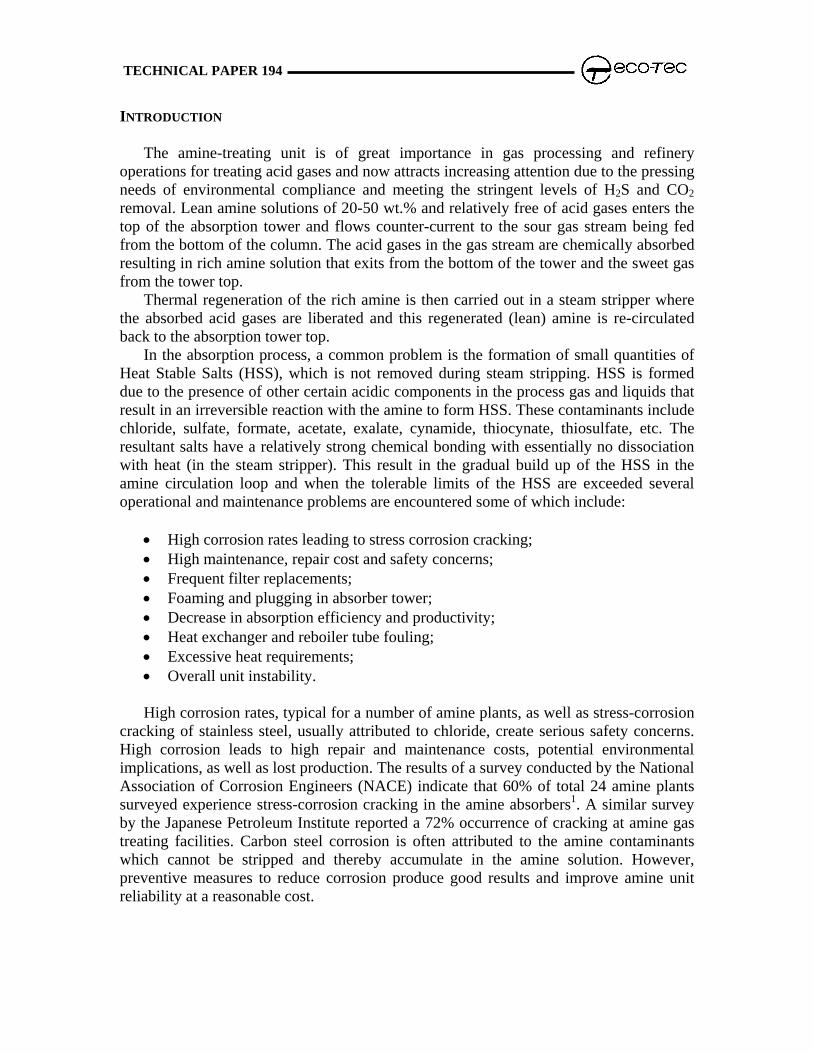
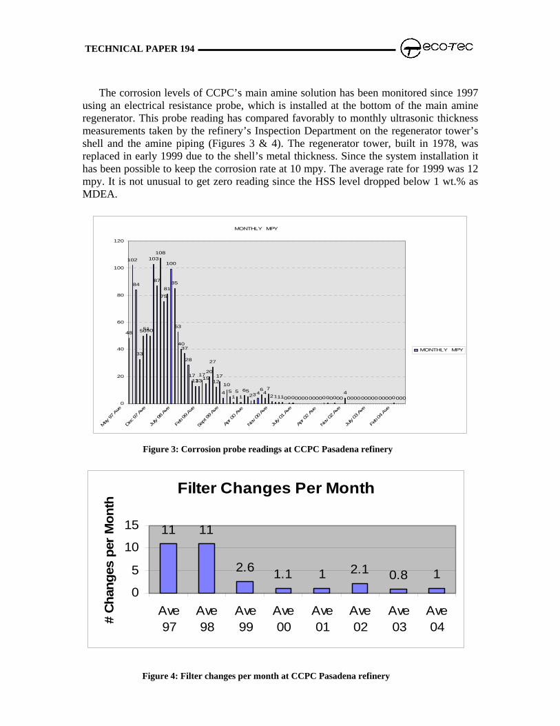
The corrosion levels of CCPC’s main amine solution has been monitored since 1997 using an electrical resistance probe, which is installed at the bottom of the main amine regenerator. This probe reading has compared favorably to monthly ultrasonic thickness measurements taken by the refinery’s Inspection Department on the regenerator tower’s shell and the amine piping (Figures 3 & 4). The regenerator tower, built in 1978, was replaced in early 1999 due to the shell’s metal thickness. Since the system installation it has been possible to keep the corrosion rate at 10 mpy. The average rate for 1999 was 12 mpy. It is not unusual to get zero reading since the HSS level dropped below 1 wt.% as MDEA.
MONTHLY MPY
48
102
84
33
505150
103
87
108
75
81
100
85
53
4037
28
171313
171520
27
1217
4
10515
165
234647
211100000000000000000400000000000000000
0
20
40
60
80
100
120
y 97
Ave
Dec 97
Ave
July
98 Ave
Feb 99
Ave
Sept 99 Av
e
Apr 0
0 Av
e
Nov 00
Ave
July
01 Ave
Apr 0
2 Av
e
Nov 02
Ave
July
03 Ave
Feb 04
Ave
Ma
MONTHLY MPY
Figure 3: Corrosion probe readings at CCPC Pasadena refinery
Filter Changes Per Month
11 11
2.6 1.1 1 2.1 0.8 10
5
10
15
Ave97
Ave98
Ave99
Ave00
Ave01
Ave02
Ave03
Ave04#
Cha
nges
per
Mon
th
Figure 4: Filter changes per month at CCPC Pasadena refinery
TECHNICAL PAPER 194
The tail gas amine unit has also been connected to the unit to allow removing the HSS
from this amine unit, eliminating the need for “bleed and feed” and reducing the amine consumption associated with this operation. The flexibility that the unit provides allows the removal of the HSS from either of the amine systems on a campaign type approach. The plan is to maintain both amine systems at HSS levels below 2%, with other benefits as detailed in Table 1.
HSS incursion rate: 1 wt. % per month (as MDEA)
Amine inventory: 15,000 Usgal
Item Description Benefit Annual savings (USD)
HSS concentration
decreased from avg. 3.5 to 0.4 wt.% as MDEA
reliable operation
Amine foaming tendency
height/break parameters changed from 450/23 to 50/4
less foaming - operating benefits
Power for reboiler
lower fouling of heat exchangers
lower energy consumption
Chemical cleaning of the absorber tower
decreased from 3 times per year to zero
eliminated cost $16,500
Corrosion decreased from avg. 60 mpy to avg. 12 mpy
great long-term maintenance savings
Filter replacement
replacement frequency decreased several times
Labor and material savings
$23,000
Amine inventory amount of free amine increased by 3.1 wt.% (as HSS level decreased from avg. 3.5 to avg. 0.4 wt.%)
more amine is available to treat acid gas; cost savings and operating benefits
Other costs elimination of previously used practice of HSS control
$35,000
Reduced amine loss
lower and more consistent absorber feed rates (less fouling and foaming)
cost savings $120,000
Additives antifoamer use eliminated cost savings $300
Table 1: Benefits of AmiPur™ Installation at CCPC Pasadena Refinery
TECHNICAL PAPER 194
CASE STUDY II: SINOPEC ZHENHAI REFINERY, CHINA
Number 2 catalytic cracking unit in Zhenhai refinery, China, has cracking capacity of 3,000,000 Tonne/year. This FCC unit is connected to an amine-scrubbing unit using MDEA, which treats 160,000 Tonne/year of dry gas and 450,000 Tonne/year of LPG. In 2001, treating capacity of LPG was increased to 600,000 - 700,000 Tonne/year.
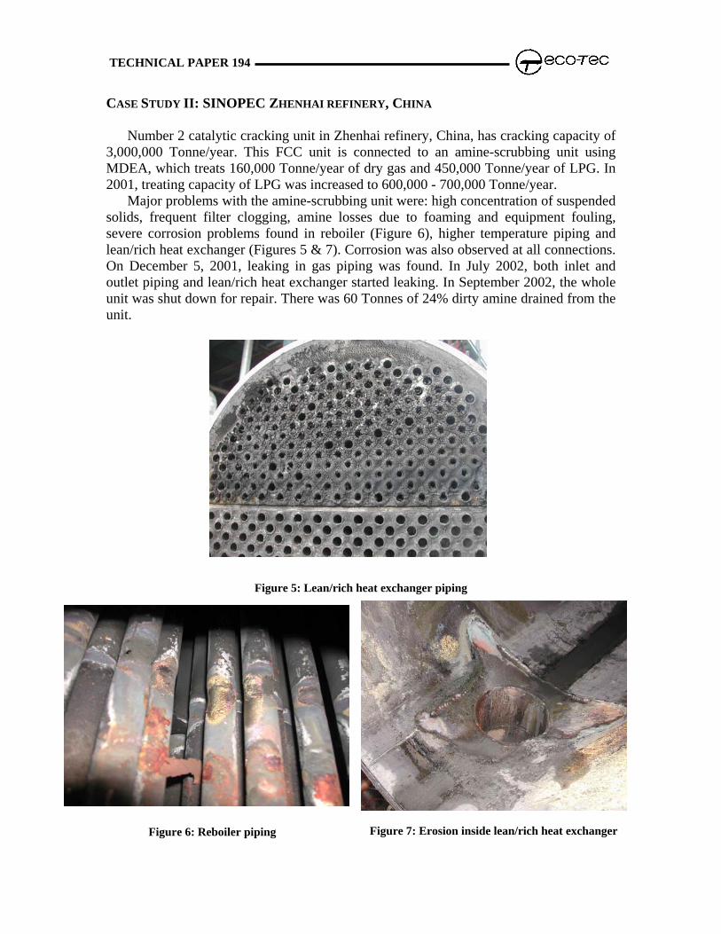
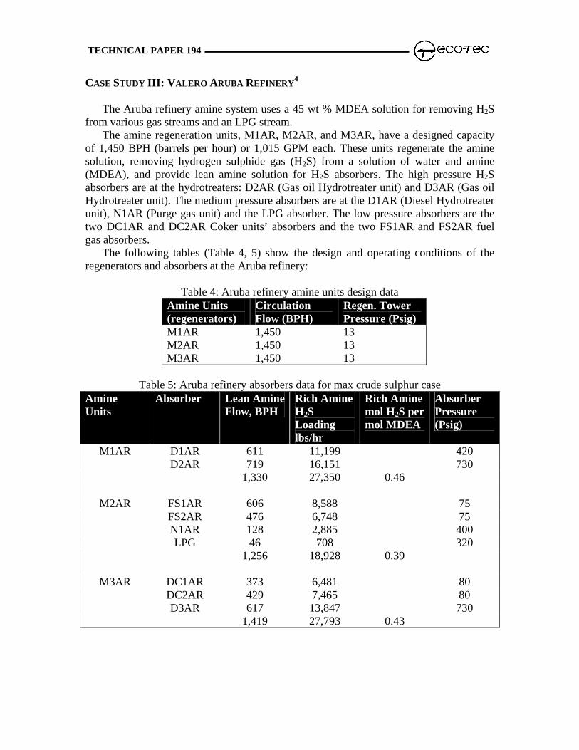
Major problems with the amine-scrubbing unit were: high concentration of suspended solids, frequent filter clogging, amine losses due to foaming and equipment fouling, severe corrosion problems found in reboiler (Figure 6), higher temperature piping and lean/rich heat exchanger (Figures 5 & 7). Corrosion was also observed at all connections. On December 5, 2001, leaking in gas piping was found. In July 2002, both inlet and outlet piping and lean/rich heat exchanger started leaking. In September 2002, the whole unit was shut down for repair. There was 60 Tonnes of 24% dirty amine drained from the unit.
CONTINUOUS AMINE PURIFICATION UNIT OPERATION AT ZHENHAI REFINERY
Based on the HSS analysis results shown in Table 2, an online, continuous amine purification unit was selected to keep the system HSS level below 1 wt.% (as MDEA). There are two operation modes: high HSS mode and low HSS mode. The high mode is used to bring HSS level down to 1 wt.% as fast as possible. The low mode will keep the HSS concentration in amine solution below 1 wt.%
Date 6/22 6/25 6/26 6/27 6/28 6/29 7/2
HSS,wt% 6.42 6.75 6.76 6.81 6.82 6.90 7.2
Table 2: #2 FCC amine scrubbing unit Heat Stable Salt analysis results in 2001
The system was installed on August 11, 2003 and started up on August 22, 2003. By September 6, the system had been running for 2300 cycles at high HSS mode and the HSS level was brought down from 3.8 wt.% to 1.0 wt.%. The system was switched to low HSS mode and the HSS level in solution has been kept below 1 wt.% (as MDEA), lowest at 0.27 wt.%, as shown Figure 8.
Figure 8: HSS level change in amine solution at Zhenhai refinery, China
TECHNICAL PAPER 194
Due to the continuous removal
of HSS by the system, the corrosion rate was decreased dramatically. Average corrosion rate at the top of the regenerator before installation was 90 mpy as shown in Figure 9. When HSS level was brought down to 0.5 wt.%, the corrosion rate at the top of regenerator is as low as 2 mpy, shown in Figure 10.
When HSS level was 6 wt.% (as MDEA), foam height was 20 cm and break time was 20 seconds. Because of the low HSS level, both foam height and break time in #2 FCC amine unit are obviously better than other amine units, especially break time, shown in Table 3. When the HSS level is lowered, more amine is available for sour gas treating. In Zhenhai refinery, a 25% of amine savings was realized one month after the start up of the system.
wt%), foam height(cm), and break time(s) ts at Zhenhai refinery, China
TECHNICAL PAPER 194
CASE STUDY III: VALERO ARUBA REFINERY4
The Aruba refinery amine system uses a 45 wt % MDEA solution for removing H2S
from various gas streams and an LPG stream. The amine regeneration units, M1AR, M2AR, and M3AR, have a designed capacity
of 1,450 BPH (barrels per hour) or 1,015 GPM each. These units regenerate the amine solution, removing hydrogen sulphide gas (H2S) from a solution of water and amine (MDEA), and provide lean amine solution for H2S absorbers. The high pressure H2S absorbers are at the hydrotreaters: D2AR (Gas oil Hydrotreater unit) and D3AR (Gas oil Hydrotreater unit). The medium pressure absorbers are at the D1AR (Diesel Hydrotreater unit), N1AR (Purge gas unit) and the LPG absorber. The low pressure absorbers are the two DC1AR and DC2AR Coker units’ absorbers and the two FS1AR and FS2AR fuel gas absorbers.
The following tables (Table 4, 5) show the design and operating conditions of the regenerators and absorbers at the Aruba refinery:
Table 4: Aruba refinery amine units design data Amine Units (regenerators)
Circulation Flow (BPH)
Regen. Tower Pressure (Psig)
M1AR 1,450 13 M2AR 1,450 13 M3AR 1,450 13
Table 5: Aruba refinery absorbers data for max crude sulphur case
The Aruba refinery observed high amine losses, high H2S in the fuel gas, and poor unit reliability at the amine regeneration units. High corrosion rates resulted in leaking of the lean/rich exchangers and also the lean amine coolers; for example, the leaking lean amine cooler resulted in seawater contamination of the amine at M3AR unit. After exchanger tube repairs, the unit equipment were washed with clean water and the unit was replenished with fresh amine. Contamination and foaming caused great losses of the solution and off spec treated gas.
In an effort to correct the many problems at the amine units, and at the same time accommodate higher projected sulphur loads (at higher sulphur crude rates) while minimizing cost, it was agreed to revamp the existing amine units. The units were originally designed for MEA but were revamped for MDEA. The revamp directive included higher amine circulation rates and higher MDEA concentration of 45 wt. %.
As part of the revamp, the capacity of each amine regeneration unit was increased to 1,450 BPH (1,015 GPM), from 1,000 BPH (700 GPM) at M1AR and M2AR units, and 1,250 BPH (875 GPM) at M3AR unit. The revamp included larger feed flash drum to increase the residence time and prevent hydrocarbon carryover to the amine regenerator.
After the revamp the Heat Stable Salts (HSS) buildup rate was 1.3 wt. % per month. This increase in HSS buildup rate since the 2003 revamp can be attributed to better amine operation and lower amine losses.
The primary HSS’s are formate and thiocyanate anions, which are degradation byproducts from the delayed coker units. The upper limit recommended for formate is 500 ppmw, but numbers as high as 19,600 ppmw have been measured at the amine unit. These heat stable salts are formed with MDEA in the presence of CO or HCN. The amine stream treating the coker gas showed a high amount of HSS between 3.0 and 8.5 wt. %. Although DuPart, Bacon and Edwards mentioned in their 1993 paper that “HSS should not exceed 10% of total amine circulation, we believe that this number should be much lower for the Aruba refinery based on our observations.”5 Rooney, Bacon, and DuPart have stated in a later 1997 article: “Total HSAS level should not exceed 0.5% of the total solution.
The iron in solution had increased from 11 to 40 ppmw since the revamp, and was an
indication of increased corrosion in the amine system. The dark color of the amine and frequent filter replacements also confirmed the corrosion mechanism, due to high HSS.
TECHNICAL PAPER 194
HSS REMOVAL SKID
In June 2005, an AMIPUR skid for Heat Stable Salt removal was installed and commissioned. The project took 11 months to purchase, design, and construct.
This AMIPUR skid includes a resin bed, cartridge filters for lean amine and water, caustic reservoir, and a PLC panel for automatic control. The skid is designed to remove dissolved heat stable acid salts from a 21.8 GPM flow of M3AR lean amine. The key to the AMIPUR process is the ion exchange resin used to absorb the heat stable acid salts dissolved in the circulating amine solution. The AMIPUR also uses a six step process and low strength caustic to regenerate the resin bed. The operating cycle period can be changed to Low, Medium, and High depending on the content of heat stable salts in the lean amine feed.
Before the commissioning of the AMIPUR skid, the M3AR amine unit was frequently replenished with fresh MDEA to maintain a low HSS in the amine solution. The contaminated HSS amine was removed from the amine unit and stored in ISO containers; this amine continues to be slowly reintroduced to the M3AR unit for HSS reduction by the AMIPUR skid. At the M3AR amine unit, the HSS was reduced to below 4 wt.% by the AMIPUR unit; this resulted in less filter change-outs. See Figure 11 for a history of filter replacement costs.
Figure 11: Total Filtration Cost (Lean and Rich) Including Manpower and Utilities/Month
TECHNICAL PAPER 194
No MDEA has been purchased since the AMIPUR start-up in 2005. Without the AMIPUR, amine change-out at M3AR would have to be done every 3 months at an annual cost of over $250,000 in amine cost only. See Figure 12 for a history of MDEA consumption.
Figure 12: Total MDEA Consumption
The problems of high amine losses, high H2S in the fuel gas, and poor unit reliability at the amine units of the Aruba refinery are now in the past. The revamps, the AMIPUR skid, and the various parameter changes have resulted in significant savings and improved amine unit reliability for the Aruba refinery. Based on savings of amine purchases and filter replacement, the HSS removal system had a payback of less than one year.
TECHNICAL PAPER 194
AMINE PURIFICATION TECHNOLOGY FOR CO2 SEQUESTRATION
Carbon Dioxide (CO2) sequestration, or capture and storage applications offer opportunities to reduce green house emissions from coal and other fossil fuel energy used in industrial applications. The most widely used and accepted method of CO2 capture is through post combustion use of amine solvents. For over 60 years, amine “scrubbing” has been instrumental in oil and gas processing applications. For CO2 sequestration, the underlying difference in the process is the large-scale production required for the removal of CO2 from flue gas.
Amines used for CO2 capture can present challenges for the operation such as increasing solvent efficiency, increasing regeneration efficiency, and reducing solvent degradation. Each of these challenges can be addressed by implementing an amine purification system into the design. An amine purification system must be able to continuously remove amine impurities to avoid the many problems associated with solvent and overall process efficiency.
By consistently maintaining low HSS levels, continuous purification results in reduced corrosion, and reduced operating costs. This efficient, advanced ion exchange method for continuously removing impurities offers high purity, reclaimed amine (Figure 13).
Figure
Different from gas processing, CO2 sequesdemands, requiring that the amine purificationcapacity needs. Another important consideration to reduce solvent degradation and loss. Effectivewith efficient regeneration address this consideraoperating costs.
13: Amine Purification System for CO2 Sequestration
tration operations have larger capacity system be scalable to meet the large is the amine purification system’s ability systems that incorporate high capacity tion and provide opportunities for lower
TECHNICAL PAPER 194
CONCLUSION
Amine unit operation is an important part of environmental compliance. Amine degradation causes the formation of heat stable amine salts (HSS) that can lead to corrosion. The amine unit performance begins to deteriorate as the HSS increase, and the H2S absorber becomes less stable. Iron in solution increases, amine filter life starts to fall, and equipment corrosion and fouling can lead to an unscheduled outage.
One of the most important results of a continuous amine purification system installation is the STABLE and RELIABLE operation of the amine plant, which in turn has a dramatic environmental impact. The continuous removal of HSS has immediate and easily quantifiable results: reduction of filtration costs; elimination of periodic chemical cleaning of the absorber tower; improved gas treating capacity of the unit; elimination or reduced use of anti-foaming additives, neutralizers and corrosion inhibitors; elimination of the costs associated with previously used methods of HSS removal.
The system installed at Crown Central Petroleum, demonstrated the benefits of continuous removal of HSS for the refinery operation. The project demonstrated a payback in the range of four (4) months, exceeding original projections for a six-month payback. Amine technology within CO2 sequestration continues to prove its effectiveness. Efficiencies and lower operating costs can be achieved with advanced ion exchange technology for the purification of amines in multiple industries.
CITATIONS 1 Mogul M. G., Hydrocarbon Processing, 78 (10), 47-56, (1999) 2Daria J., Davy P., Sheedy M. The 2000 Laurance Reid Gas Conditioning Conference,
February 27 – March 1, 2000, Norman, OK 3Davy P., Daria J. Brimstone Sulfur Recovery Symposium, September 14 – 17, 1999,
Colorado 4 Lampe-Chicquito, Rubiëla, Charles, Cedric, The 2008 Laurance Reid Gas Conditioning
Conference, February 24 – February 27, 2008, Norman, OK 5 DuPart M.S., Bacon, T.R., and Edwards, D.J. “Understanding Corrosion in Alkanolaine
Gas Treating Plants,” Part 2 Hydrocarbon Processing, 1993. 6 Rooney, P.C., Bacon, T.R., and DuPart, M.S., “Effect of Heat Stable Salts on MDEA
Solution Corrosivity,” Part 2, Hydrocarbon Processing, April 2007.