Effects of Radiation Trapping on Mode Competition and Dispersion in the Ring Laser Frederick Aronowitz By considering the phenomena of radiation trapping, corrections are obtained in the third order Lamb co- efficients for the amplitude and frequency ring laser equations. The corrected coefficients allow the cor- rect prediction of the shape of the experimentally measured Lamb dip. They also allow the prediction of mode competition between the oppositely directed traveling waves near the Doppler center. As found experimentally, this competition region is predicted to increase with increasing pressure. Expressions are given for the Lamb coefficients that are obtained from an exact third order integration. Mode Competition Effects in the Ring Laser Mode competition between the oppositely directed traveling waves (ODTW) in the He-Ne ring laser has been observed by a number of workers.'- 7 Competi- tion occurs when the neon consists mainly of a single isotope. In a typical ring laser oscillating at 1.15 gim, the addition of a few percent of a second isotope is sufficient to eliminate the mode competition. For the 0.633-gim transition, competition can still occur with as much as 10% of a second isotope. 7 Mode competition has been observed 7 with a natural neon mixture (91% " 0 Ne:9% 22 Ne). The reason for the reduction in the ability of the second isotope to quench the mode com- petition for the 0.633-gm transition is due to the larger isotope separation for this transition. The separation between the ' 0 Ne and Ne transition centers is 875 MHz and 261 MHz for the 0.633-,4m and 1.15-gm transitions, respectively. The competition between the ODTW is found in the region of frequency tuning near the Doppler center of the dominant isotope transition.'- 7 The competition is usually observed for the case of both ODTW being locked to a common frequency. However, competition has been observed for an unlocked ring laser. 2 ' 3 ' 8 The removal of the frequency degeneracy has been caused by both the insertion of a nonreciprocal phase element in the cavity 2 ' 3 and actual physical rotation of the cav- ity. 8 At low pressures (a few torr) the competition takes the form of oppositely directed narrow spikes (widths are a few to tens of M\'IHz, depending on the backscatter- The author is with the Systems & Research Center, Honeywell, JIlc., St. Paul, Miniiesota 55113. Received 14 June 1972. ing coupling) located at the center of the Lamb dip. 9 For low gain or higher gas pressure, although no Lamb dip is observed, competition still occurs. In the com- petition region, the amplitudes of the ODTW vary dramatically with small frequency excursions. In the stationary ring laser, with no nonreciprocal phase ele- ment in the cavity, it is possible for the ODTW to be either frequency synchronized or unlocked. In the un- locked state, the beat frequency is on the order of and greater than the lock-in threshold. 4 ' 7 The competition is also a very strong function of backscattering- coupling between the ODTW and gas pressure. 4 9 The competition region typically increases with increase of both parameters. At higher total gas pressures (greater than approxi- mately 5 Torr), the competition is strong enough to sup- press one of the ODTW."l 9 In the center of the com- petition region, both beams can exist in the form of un- locked traveling waves. The competition region in- creases with increasing pressure. Anomalies in Theoretical Analysis Previous attempts have been made to explain the described mode competition."'1 0 - 6 In the first pub- lished description of mode competition,' two amplitude equations of the form lI/l = al- l1- 01212 = 0, 12/12 = 2 - 212 - 02I = 0, (la,) (lb) were considered. In Eqs. (1) I, and I2 are the intensi- ties (expressed in dimensionless Lamb units 8 ) of the ODTW. The a, , 0 are the Lamb coefficients 7 ", 8 de- scribing the excess gain over threshold, self-gain satura- tion, and mutual gain saturation, respectively. The functional form of the coefficients is given in Appendix A. 2146 APPLIED OPTICS / Vol. 11, No. 10 / October 1972
Transcript
Effects of Radiation Trapping on Mode Competitionand Dispersion in the Ring Laser
Frederick Aronowitz
By considering the phenomena of radiation trapping, corrections are obtained in the third order Lamb co-efficients for the amplitude and frequency ring laser equations. The corrected coefficients allow the cor-rect prediction of the shape of the experimentally measured Lamb dip. They also allow the prediction ofmode competition between the oppositely directed traveling waves near the Doppler center. As foundexperimentally, this competition region is predicted to increase with increasing pressure. Expressionsare given for the Lamb coefficients that are obtained from an exact third order integration.
Mode Competition Effects in the Ring Laser
Mode competition between the oppositely directedtraveling waves (ODTW) in the He-Ne ring laser hasbeen observed by a number of workers.'- 7 Competi-tion occurs when the neon consists mainly of a singleisotope. In a typical ring laser oscillating at 1.15gim, the addition of a few percent of a second isotope is
sufficient to eliminate the mode competition. For the0.633-gim transition, competition can still occur with asmuch as 10% of a second isotope.7 Mode competitionhas been observed7 with a natural neon mixture (91%"0Ne:9% 2 2Ne). The reason for the reduction in theability of the second isotope to quench the mode com-petition for the 0.633-gm transition is due to the largerisotope separation for this transition. The separationbetween the '0Ne and Ne transition centers is 875MHz and 261 MHz for the 0.633-,4m and 1.15-gmtransitions, respectively.
The competition between the ODTW is found in theregion of frequency tuning near the Doppler center ofthe dominant isotope transition.'-7 The competition isusually observed for the case of both ODTW beinglocked to a common frequency. However, competitionhas been observed for an unlocked ring laser.2' 3' 8 Theremoval of the frequency degeneracy has been causedby both the insertion of a nonreciprocal phase elementin the cavity2' 3 and actual physical rotation of the cav-ity. 8
At low pressures (a few torr) the competition takesthe form of oppositely directed narrow spikes (widthsare a few to tens of M\'IHz, depending on the backscatter-
The author is with the Systems & Research Center, Honeywell,JIlc., St. Paul, Miniiesota 55113.
Received 14 June 1972.
ing coupling) located at the center of the Lamb dip.9
For low gain or higher gas pressure, although no Lambdip is observed, competition still occurs. In the com-petition region, the amplitudes of the ODTW varydramatically with small frequency excursions. In thestationary ring laser, with no nonreciprocal phase ele-ment in the cavity, it is possible for the ODTW to beeither frequency synchronized or unlocked. In the un-locked state, the beat frequency is on the order of andgreater than the lock-in threshold.4' 7 The competitionis also a very strong function of backscattering-coupling between the ODTW and gas pressure.4 9 Thecompetition region typically increases with increase ofboth parameters.
At higher total gas pressures (greater than approxi-mately 5 Torr), the competition is strong enough to sup-press one of the ODTW."l 9 In the center of the com-petition region, both beams can exist in the form of un-locked traveling waves. The competition region in-creases with increasing pressure.
Anomalies in Theoretical Analysis
Previous attempts have been made to explain thedescribed mode competition."'1 0- 6 In the first pub-lished description of mode competition,' two amplitudeequations of the form
lI/l = al- l1- 01212 = 0,
12/12 = 2 - 212 - 02I = 0,
(la,)
(lb)
were considered. In Eqs. (1) I, and I2 are the intensi-ties (expressed in dimensionless Lamb units 8 ) of theODTW. The a, , 0 are the Lamb coefficients7",8 de-scribing the excess gain over threshold, self-gain satura-tion, and mutual gain saturation, respectively. Thefunctional form of the coefficients is given in AppendixA.
Equations (1) were shown to predict mode competi-tion between the ODTW at the Doppler center.17 Inaddition, the presence of a second isotope was shown toeliminate the mode competition. However, the anal-ysis was incomplete in that it did not include the effectsof mode coupling due to backscattering.1 ' 0"19"20
In a later work' the effects of backscattering wereconsidered, and Eqs. (1) were found to be modified toinclude the terms: r2(I2/I1)1 cos(4k + E2) and ri(II/I2)1cos(N - a,), respectively. The ri', i = 1,2 are the frac-tional power coupling coefficients for each beam; e, i =1.2 are scattering phases; 4' is the instantaneous phasedifference between the ODTW. An expression for thebeat frequency P was also given.
It has been shown that the backscattering terms can-not be neglected.2 For the 0.633-gm transition op-erated in the low gain region so that the third orderpolarization expansion resulting in Eqs. (1) is valid, thebackscattering coefficient r is typically on the order ofa.
Computer analysis of Eqs. (1), with the inclusion ofbackscattering, showed the backscattering to be thedominant cause of mode competition.' However, aninconsistency was found with respect to the shape of theLamb dip.2" For conceptual ease in the analysis ofEqs. (1), only the dominant terms in 3 and 0 need beconsidered. Then, as can be shown (see Appendix A)for symmetric Lamb coefficients and for a single isotope,
0 = 02(0) (2)
where
2(t) = [ + /n)2] -1. (3)
In Eq. (3) is a measure of frequency detuning from theDoppler center and X is the ratio of the collision-broad-ened homogeneous line width to the Doppler-broadenedinhomogeneous line width.
If mode competition and backscattering are neglected,Eqs. (1) and (2) give an expression for the intensity(assuming equal ODTW) as
I = (a/0)(1 + £)-'. (4)
As has been found in the linear laser, Eq. (4) predicts aLamb dip that is narrower and deeper than found ex-perimentally.2" Experiments232 4 have shown that theshape of the Lamb dip can be predicted correctly if theLorentzian given by Eq. (3) is replaced by
£ - r2, (5)
ysis of the solutions of Eqs. (1). It can be shown thatstable solutions exist for I, and I2 provided that
12 - 12021 > 0- (7)
With the inclusion of r in the 0 terms, the inequalitygiven by Eq. (7) is satisfied for all values of frequencytuning. With the inclusion of backscattering, Eq. (7)is modified, but the conclusion remains unchanged: noinstability and hence no mode competition occurs.
As shown in Appendix B, when is neglected, theinequality given by Eq. (7) is not satisfied in the regionof the Doppler center. The instability region given by0 > /3 is found to increase with increasing pressure.
Thus, in considering pressure effects for the ring laser,two conditions must be satisfied: (1) to predict the cor-rect shape of the Lamb dip, the Lorentzian in the de-nominator of Eq. (4) must have a pressure-dependentcoefficient less than unity; (2) to predict correctlymode competition, the 0 terms in Eqs. (1) must belarger than the 3 terms in a narrow region around theDoppler center. This difficulty can be resolved by theinclusion of the phenomena of radiation trapping."-' 8
It should be noted, however, that any strong collisionmodel' 9" 0 that causes a uniform redistribution of ex-cited atoms over the Maxwellian velocity distributionwill also give the desired results.
Radiation Trapping
Bennett introduced the concept of hole burning in thefollowing manner."," As shown in Fig. 1, curve arepresents the unsaturated Doppler-broadened gainprofile for the transition. When laser oscillations occur,the gain is nonuniformly saturated. This results intwo holes having a width that is determined by the life-time of the atoms in the upper and lower transitionstates. The lifetime is determined both by the uncer-tainty principle and de-exciting collisions.
The saturation analysis holds for both the ring andlinear laser. In the linear laser the standing wave is
GAIN
r 2 El (Il
2) 2dFREQUENCY- -
Fig. 1. Inhomogenous and homogeneous gain saturation.Curve b shows the uifsaturated gain in the absence of laser oscilla-tions. Curve a shows the effects of homogeneous saturation dueto radiation trapping. The inhomogenous line saturation due totraveling waves I1 and 12 are shown as Lorentzian holes burned intothe gain curve. The gain curve is shown for either a linear laser
or a ring laser with both beams frequency synchronized.
LOSS.r
where
r = n/?7. (6)
The coefficient r is pressure dependent, and typicalvalues are on the order of 0.4.
With the inclusion of in Eqs. (1) and (2), correctexpressions can be obtained for the Lamb dip shape inthe absence of mode competition. However, a diffi-culty arises in that even with the inclusion of back-scattering in Eqs. (1), no mode competition can be pre-dicted. The difficulty can be seen in the stability anal-
treated as a pair of ODTW. For a cavity resonant fre-quency located away from the Doppler center, the inter-action of the field with moving atoms results in thetwo holes being burned on opposite sides of the gaincurve. This occurs because separate ensembles ofatoms interact with each ODTW. This is necessarysince each atom must see the field as being resonanceradiation in its own frame.
In the manner shown by Bennett'0 for the linear laser,Eqs. (1) under steady state conditions can be derivedfrom Fig. 1. The gain curve in Fig. 1 has been writtenwith respect to a test signal traveling in the direction ofbeam Ii. To consider the saturation effects on beam I2,a separate gain curve must be drawn and relabeled.' 7
In the case of both ODTW oscillating at the same fre-quency, the two gain curves are identical.
Writing the depth of the holes caused by beam Ii as d,the gain-equals-loss condition for beam I, gives
g 1 -Y-di-d 2 = 0. (8)
In Eq. (8), d2-C is the reduction in gain seen by beam Il.This is caused by the Lorentzian tail of the image holecaused by beam 12.
In a similar fashion, the gain-equals-loss condition forbeam 12 gives
g2- y-d2-dl£ = 0. (9)
Comparing Eqs. (1), (8), and (9), the depth of the hole,which is proportional to the strength of the saturatingfield, is given by
di = 1i3i. (10)
Using Eqs. (2) and (10), Eqs. (8) and (9) become
1- - - 01212 = (la)92 - Y - 212 - 02,I1 = 0 (llb)
Equations (11) can be modified to take into accountthe effects of radiation trapping. It is known that fortypical operating pressures of the He-Ne laser, spon-taneous emission from the upper laser level tends to beresonant absorbed by ground state neon atoms.2"-28
This results in an increased effective lifetime of theatoms in the upper laser state. It also results in a mix-ing of the velocity distribution of the gain atoms. (Themixing occurs because the atoms spontaneously emit inall directions, while the velocity distribution is measuredwith respect to the axis of the laser tube.) Treatingthis mixing as a homogeneous contribution to gainsaturation that is proportional to the radiation field,the gain-equals-loss condition given by Eqs. (8) and (9)becomes modified. This modification can be seen inFig. 1, if we take curve b to be the unsaturated gain.Then the effective (saturated) gain becomes
9i * 9i- i(Il + 2), i = 1,2. (12)
In Eq. (12) is proportional to the unsaturated Doppler-broadened gain curve. The homogeneous saturation isexpressed in terms of the sum of the ODTW.
Using Eq. (12), Eq. (11) becomes
1- Y = (l + 8)I + (012 + 2)I2,
92 - 72 = (2 + 282)12 + (021 + 182)11-
(13a)
(13b)
The homogeneous saturation parameter can bedetermined from experimental power tuning data ob-tained with the linear laser."" In this case, writingh = I = I, Eq. (13) becomes
I = (g --Y)(3 + 0 + )-'.
Using Eq. (2), Eq. (14) becomes
I = r[(g - )/f] [i + in)] -lwith
r = (l + 8/1)'
(14)
(15)
(16)
Equation (15) is the accepted expression23 for the out-put power and includes the pressure-dependent con-tribution to the normalization, as found by Smith.'8
From Eqs. (13), Eq. (17), which describes the sta-bility condition for the existence of both ODTW,becomes
(1 + 281)(2 + 282) - (012 + 418)(021 + 82) > 0- (17)For frequency tuning near the Doppler center, such that0 > /3, Eq. (17) is not satisfied, and mode competitionwill occur.
Therefore, by including the homogeneous contribu-tion to gain saturation due to radiation trapping, boththe shape of the Lamb dip and mode competition can bepredicted.
Dispersion
Any phenomena that affects the line shape of theatomic transition will cause anomalous dispersion effects.Since the line shape changes are caused by saturation,the dispersion is expected to be a function of the outputpower of the laser. Using the simple saturation modewith respect to Fig. 1, power dependent corrections tothe oscillation frequency can be obtained.
Figure 2 shows the dispersion curves that correspondto the gain curves in Fig. 1. Curve c represents thedispersion of the empty cavity that is linear in fre-quency. The empty cavity oscillation frequency isdetermined by the net-phase-per-pass-equals-zero con-dition. Curve b represents the dispersion curve due tothe unsaturated gain curve. For frequencies lessthan the Doppler center, the additional phase per passdue to the unsaturated dispersion of the active mediumresults in a negative phase contribution. Hence theoscillation frequency is pulled toward the Dopplercenter, resulting in the positive empty cavity dis-persion compensating for the negative active mediumdispersion. This mode pulling is not power dependent.
The inhomogeneous saturation due to the image holeresults in a Lorentzian-type dispersion curve. This iscentered at the image hole and is of negative sign to theunsaturated Gaussian dispersion. As can be seen inFig. 2, it provides a power-dependent correction thatpushes the oscillation frequency away from the Dopplercenter. Note that since the dispersion curve is an oddfunction in this simple model, a hole cannot push on
Fig. 2. Correction to the empty cavity oscillation frequency dueto dispersion of the active medium. The phase shifts are shownfor beam I,. Curve c represents the dispersion of the emptycavity, for an oscillation frequency Vl,,. Curve b represents theadditional unsaturated phase shift per pass due to the laser transi-tion. Curve a represents the saturated phase shift caused byradiation trapping. Curve d represents the correction to thephase shift caused by inhomogeneous saturation that results in
the image hole.
itself to first order. Higher order corrections are givenin Appendix A.
Radiation trapping results in gain saturation that uni-formly reduces the unsaturated gain. This causes areduction in the amplitude of the dispersion curve asshown by curve a in Fig. 2. It also causes a pushingof the oscillation frequency away from the Dopplercenter.
For both ODTW in a ring laser, the corrections to theempty cavity oscillation frequency can then be ex-pressed as
W = wCo + o4[ - 8(I, + 12)/G] + 71212, (18a)
W2 = Wo2 + 2[1 - 22(11 + I2)/G] + T21I1. (18b)
The a and are the pulling and pushing Lamb coeffi-cients and are given in Appendix A.
Subtracting Eqs. (18b) and (18a), the beat fre-quency between the ODTW is given as
C2 - WI = (o2 - 0.1) + (2- cr) + (2II - T1212)
- 4(1, + 12)(0f22 - 0a18)/G. (19)
The last expression in Eq. (19) is new. It is the cor-rection to the beat frequency that is due to differentialmode pushing that arises from homogeneous gain satura-tion due to radiation trapping. The first term is therotational cavity splitting and has been denoted as .The third term is a null shift arising from nonreciprocallosses and will not be considered further. The secondterm is a scale factor correction due to differential modepulling and is of importance in the operation of thelaser gyro.
To estimate the magnitude of the new homogeneoussaturation mode pushing term, consider first the differ-ential mode pulling term. For simplicity, only a singleisotope system will be considered. In actual practice,an equal mixture of isotopes is used. However, this
only complicates the analysis without adding furtherinsight.
An expression for the coefficient is given in AppendixA. Evaluating 0-2 and al by making a Taylor expansionabout the stationary cavity frequency I, the differentialmode pulling is found to be
02- al = Q(c/2L)(G/Ku)Zr'(t)/Z(0). (20)
The derivative of the dispersion curve, (Zr'), is a bell-shaped curve opening upward, and Z,' < 0 over most ofthe operating range. The linear dependence of thedifferential mode pulling on the rotation rate accountsfor the term being a scale factor.
The saturation term can be evaluated in similarfashion. From Eq. (16)
2= J12,#2, (21)
where
r = r-' -i. (22)In Eq. (22), f is an increasing function of pressure andtypically varies from 1 - 2.5. Again, using a Taylorexpansion, the homogeneous saturation term in Eq.(19) becomes
- (c/2L)(G/Ku)I[Z t (t)Zi(j) + Z,(t)Zj'(t)] /Zi(o), (23)
where
I = 2(I + I2). (24)
Near line center (t 0) the term in Zr can be neglected,and as seen from Eq. (20), Eq. (23) becomes
-I~re2 - cr,). (25)
Equation (25) shows a power- and pressure-dependentreduction in the scale factor correction.
Conclusion
By including the effects of radiation trapping, it hasbeen shown that modification to the third-order Lambcoefficients arises in both the amplitude and frequencyring laser equations. The corrected coefficients havebeen shown to predict correctly the experimentally ob-served shape of the Lamb dip. In addition, they alsoallow for the case of < 0 near the Doppler center for asingle isotope system. This allows prediction of theexperimentally observed mode competition between theoppositely directed traveling waves. Previously, bothphenomena were not simultaneously predictable. Inthe frequency equations, radiation trapping predicts apower dependent reduction in the scale factor correc-tion for the laser gyro. Experimental confirmation ofthis correction has not been made. In addition, ex-pressions are given for the exact third-order Lamb co-efficients. The higher order corrections are necessary inthe calculation of expressions having the factor ( - 0).
Some of this work was first presented at the Confer-ence on Laser Engineering Applications, Washington,D.C., 1971.
Fig. 3. Curves ( d, e, f) and (a, b, c) show plots of Eqs. (Al)-(A3) for and (0 + ), respectively. The curves are plotted for
= 0.05, 0.1, 0.2. Both 13 and ( + ) decrease for increasingvalues of . Regions I and II correspond to the scale on theright. In region II, ( + ) > 13. This region is shown to in-
crease for increasing values of ,1.
Appendix A
Neglecting backscattering, the equations (correct tothird order) describing the amplitudes and frequenciesof the ODTW in the ring laser are
12 = (L)I,(a, - 3,I, - 0,2I2),
12 = (/L)I 2(a 2 - 1212 - 02II,),
co = 21 + a,- + Pu1, + 71212,
W2 = 2 + 72 + P2I2 + 211.
In evaluating the Lamb coefficients exactly, the inte-gral, commonly called the plasma dispersion function,"is encountered in the integration over atom velocities,
Z(t,) = 2i f dx exp(-x 2 - 2x + 2itx).
The imaginary and real parts of the plasma dispersionfunction are
Zi= f dw exp(-w)z(w + t, (A4)
Zr= f f dw exp(-w2)S(w + (+ ) (AS)
In Eqs. (1)-(5)
= ( - d)/Ku, (A)= -y/Ku, (A7)
Ku = 27rAvd/2(ln2)1, (AS)
where WCd is the transition center frequency, o is theoscillation frequency, Ad is the Doppler width of thetransition, y is a measure of the decay rate for the transi-tion line.
For the usual case of 7 < 1, an expansion of Eq. (Al)gives
72K-1
Z i exp(,72 - Z') cos2?q + 2 E (1) (2K 1 F2KK=1 (Ki! -
In Eqs. (A9) and (A10), FK is the Kth derivative withrespect to of
F(Q) = exp(-42) fJ exp(x2)dx. (All)
The derivatives of Eq. (All) satisfy the recurrence rela-tion
FK = -2[(K - 1)FK.2 + FK,_] K > 1, (A12)
and
F = F,
F, = 1 - 2tF.
In the limit of q << 1, Eqs. (A9) and (A10) become
Zi = ir0 exp(-Z2) - 2(l - 2F) + 0(271),
Z = -2F + 0r3X77 exp(-_2 ) + 0(772).
(A13)
(A14)
(A15)
(A16)
It can be shown9 that the first-order coefficients canbe expressed as
al = gZ,(4,) - IJ
al = (gc/2L)Z,(Qj),(Al)
The plasma dispersion function can be put into the form
Z % 7) = L' f dw exp(-w2)[l + i(w + t)/77]2(w + ),
(A2)
where
2(w + 0 = [1 + ( + 0)'/ho]-. (A3)
(A17)
(A18)
where
g = G/Zi(0). (A19)
In Eqs. (A17)-(A19), c/L is the longitudinal mode spac-ing and G and y are the fractional gain and losses perpass, respectively. Similar coefficients for beam I2 canalways be obtained by permuting indices. The de-pendence in the plasma dispersion function has been
Using Eqs. (A4), (A5), (A22), and (A29), Eq. (A28) be-comes
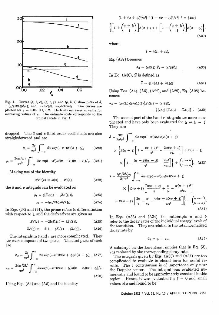
Fig. 4. Curves (a, b, c), (d, e, f), and (g, h, i) show plots of ,- (27/)S(t)Zr(t) and -2 7Zr'(t), respectively. The curves areplotted for 7 = 0.05, 0.1, 0.2. Each set increases in value-forincreasing values of . The ordinate scale corresponds to the
ordinate scale in Fig. 1.
dropped. The X and p third-order coefficients are alsostraightforward and are
+ Sw _() 2w + WW _ w0-(w + I) + (a - ).+ paw - 0 + a - 2 b ( a
(A34)
In Eqs. (A33) and (A34) the subscripts a and brefer to the decay rates of the individual energy levels ofthe transition. They are related to the total normalizeddecay rate by
27 = a + 7b- (A35)
A subscript on the Lorentzian implies that in Eq. (3),7 is replaced by the corresponding decay rate.
The integrals given by Eqs. (A33) and (A34) are toocomplicated to evaluate in closed form for useful re-sults. The 0 contribution is of importance only nearthe Doppler center. The integral was evaluated nu-merically and found to be approximately constant in thisregion. Hence, it was evaluated for t = 0 and smallvalues of - and found to be
7a277b I 4 aI l ) 0 = ir 7 I (a G+ Ia) -1+ a)(A36)
The integral i- given by Eq. (34) is an odd function in tvat = 0 and is therefore zero. The term linear in was numerically evaluated and found to be small.Therefore, this integral is neglected.
Appendix B
In this Appendix, the and 0 coefficients are exam-ined in the region of the Doppler center. The analysisshows that close to the center 0 and hence theODTW are unstable. If the 0 contribution is neglected,it is shown that 0 = i near the Doppler center. Forsimplicity the coefficients are analyzed for the lockedcase, or ( = 2 = . Then neglecting the normaliza-tion constant g, Eqs. (A23), (A30), and (A33) become
1 = Zi - Zr', (B1)
0 = (t)1zi - ()Z], (B2)
6 = 7r1(16/9)n72(1 - 4/r). (B3)
For numerical purposes, Eq. (B3) was written for thecase of 11a =
2 .
Note that since
lim -) Zr . and 2(0) = 1, (B4)
it can be seen from Eqs. (Bl) and (B2) that = 0 at= 0.Figure 3 shows a plot of 3 and ( + 0) vs for fre-
quencies close to the Doppler center. Values of - =0.05, 0.1, 0.2 were chosen. It can be seen that for in-creasing , the region (II) where the ODTW are un-stable ( > ) increases. The coefficients were eval-uated using Eqs. (A9)-(A12) in Appendix A. Z' wasevaluated using Eq. (A26) in Appendix A.
-Figure 4 shows the contribution of the different termsto the coefficient. As can be seen in both Figs. 3 and 4only the 0 terms show a variation with frequency tuning.This is due to the Lorentzian factor in 0 and the fact thatfrequency variations comparable to are being con-sidered. The other terms would show a frequency de-pendence for detuning comparable to the Dopplerwidth.
As can be seen from Fig. 4, the terms in Z, and Z/ in0 and 3 are an order of magnitude smaller than thedominant terms for X < 0.1. For higher pressures theseterms becomes relatively larger. For = 0.2 they areonly a factor of 5 smaller than the dominant term.
The term in a can be seen to be small and can be ne-glected except for terms having the factor ( - 0).
References
1. F. Aronowitz and R. J. Collins, Appl. Phys. Lett. 9, 55(1966).
2. P. H. Lee and J. G. Atwood, IEEE J. Quantum Electron.QE-2, 235 (1966).
3. J. T. Hutchings, J. Winocur, R. N. Dorrett, E. D. Jacobs,and W. L. Zingery, Phys. Rev. 152, 467 (1966).
4 V. N. Lisitsyn and B. I. Troshin, Opt. Spectrosc. 22, 363(1967).
5. B. I. Troshin, Opt. Spectrosc. 24, 51 (1969).6. I. A. Andronova and I. L. Bershten, Sov. Phys. JETP 30, 58
(1970).7. F. Aronowitz, Appl. Opt. 11, 405 (1972).8. F. Aronowitz, Unpublished.9. F. Aronowitz, Thesis, New York University (1969).
10. B. L. Zhelnov, A. P. Kazantsev, and V. S. Smirnov, Sov.Phys. JETP 23,858 (1966)
11. S. G. Zeiger and E. E. Fradkin, Opt. Spectrosc. 21, 217(1966).
12. Yu. L. Klimontovich, P. S. Landa, and E. G. Lationtsev,Sov. Phys. JETP 25, 1076 (1967).
13. E. M. Belenov and A. N. Oraevskii, Sov. Phys. Dokl. 13, 411(1968).
14. S. G. Zeiger, E. E. Fradkin, and P. P. Filatov, Opt. Spectrosc.26, 340 (1969).
15. B. L. Zhelnov, V. S. Smirnov, and A. P. Fadeev, Opt. Spec-trosc. 28, 400 (1970).
16. B. L. Zhelnov and G. I. Smirnov, Opt. Spectrosc. 28, 402(1970).
17. F. Aronowitz, Phys. Rev. 139A, 635 (1965).18. W. E. Lamb, Jr., Phys. Rev. 134A, 1429 (1964).19. H. DeLang, Appl. Phys. Lett. 9,205 (1966).20. Yu. Klimontovich, V. N. Kuryalov, and P. S. Landa, Sov.
Phys. JETP 24,1 (1957).21. F. Aronowitz and R. J. Collins, J. Appl. Phys. 41, 130 (1970).22. R. A. MacFarlane, W. R. Bennett, Jr., and W. E. Lamb, Jr.,
Appl. Phys. Lett. 2,189 (1963).23. A. Szoke and A. Javan, Phys. Rev. Lett. 10, 521 (1963).24. R. H. Cordover and P. A. Bonczyk, Phys. Rev. 188, 696
(1969).25. I. M. Beterov, Yu. A. Matyuzin, and V. P. Chebotaev, Opt.
Spectrosc. 28, 191 (1970).26. M. I. D'Ya Konov and V. I. Perel, Sov. Phys. JETP 31,
585 (1970).27. I. M. Beterov, Yu. A. Matyuzin, S. G. Ravtian, and V. P.
Chebotaev, Sov. Phys. JETP 31, 668 (1970).28. P. W. Smith, "The Effect of Cross Relaxation on the Behavior
of Gas Laser Oscillators," Quantum Electronics Conf.,Montreal (May 1972).
29. S. G. Rautian, Sov. Phys. JETP 24, 788 (1967).30. B. L. Gyorffy, M. Borenstein, and W. E. Lamb, Jr., Phys.
Rev. 169, 340 (1968).31. W. R. Bennett, Jr., Phys. Rev. 126, 780 (1962).32. W. R. Bennett, Jr., "Relaxation Mechanisms, Dissociation
Excitation Transfer and Mode Pulling Effects in Gas Lasers,"Quantum Electronics III, N. Bloembergen and P. Grivet, Eds.(Columbia U. P., New York, 1964), p. 441.
33. B. D. Fried and S. D. Conte, The Plasma Dispersion Function(Academic Press, New York, 1961).