Effects of shape of transverse cross-section on the load carrying capacity of laminated glass columns Giuseppe Campione a,⇑ , Valentino Rondello b a Università degli Studi di Palermo, Dipartimento di Ingegneria Civile Amb.le Aerospaziale e dei Materiali – DICAM, Viale delle Scienze, 90128 Palermo, Italy b Eng. Valentino Rondello, Via Clio, 91100 Trapani, Italy highlights Compressive tests on glass columns with rectangular, T and X cross-sections. Stability analyses including elastic torsional and local buckling. Buckling strength of single panels depends very much on the slenderness. Local and torsional buckling effects reduce the bearing capacity of T and X columns. article info Article history: Received 29 October 2013 Received in revised form 12 February 2014 Accepted 17 February 2014 Available online 13 April 2014 Keywords: Laminated glass Glass columns Compression Buckling Flexure Torsion abstract In this paper simplified expressions for the calculus of the load carrying capacity of glass columns having rectangular, tee (T) and cruciform (X) transverse cross-sections are proposed and verified against avail- able experimental data. Members with T and X cross-sections are obtained by gluing single multilayered glass panels. The expressions derived take into account of the: shape of the transverse cross-section (rectangular, T, and, X sections); buckling phenomenon (flexural and torsional); failure in the glued sections; long time effects. Case of full connections and absence of connections are considered to determine the range of var- iation of expressions adopted. The comparison between the analytical and the experimental results high- lights that in the case of columns or beam-like elements having rectangular cross-sections the flexural buckling resistance governs the load carrying capacity of columns, while in the case of glass columns with X and T cross-sections failure due to torsional buckling effects strongly limits the load carrying capacity of members, also penalized by the glued connection failure. Ó 2014 Elsevier Ltd. All rights reserved. 1. Introduction The interest in the use of laminated multilayered glass (LG) col- umns or beam-like elements to form glass columns is increasing today in the architecture. On this field it is widely accepted that buckling phenomenon and time depending effects are the main causes limiting the load carrying capacity of glass columns or beam-like elements (due to their b/L ratio). Several studies were addressed to analyze the effects of the shape and of the dimension of the transverse cross-section of col- umns often constituted by LG columns assembled together by two component glue based on epoxy resin. Fig. 1 shows some examples of cross-section shapes analyzed in [1] and tested in compression. Similarly, real applications refer to the use of open section for glass columns [1]. In the case of the transverse cross-section shown in Fig. 1 glass columns had length 1000 mm and they were formed by gluing sin- gle monolithic glass columns of thickness 8 mm with two-compo- nent glue based on epoxy resin. In some other cases [2,3] tee (T) and cruciform (X) cross-sec- tions were utilized to form glass columns to be tested in compres- sion. Cross-sections were formed assembling single LG columns with two-component glue based on epoxy resin. Single glass col- umns had thickness 4 mm put together though a thin interlayer of PVB with thickness t int = 1.00 mm (Fig. 2). In these cases some of the most important aspects to take into account are the following: viscoelastic and temperature depending effects governing mainly the behavior of PVB and glue; buckling phenomenon of glass columns and of single LG columns activating http://dx.doi.org/10.1016/j.conbuildmat.2014.02.053 0950-0618/Ó 2014 Elsevier Ltd. All rights reserved. ⇑ Corresponding author. Tel.: +39 091 6568467; fax: +39 091 6568407. E-mail address: [email protected](G. Campione). Construction and Building Materials 61 (2014) 349–359 Contents lists available at ScienceDirect Construction and Building Materials journal homepage: www.elsevier.com/locate/conbuildmat
Transcript
Construction and Building Materials 61 (2014) 349–359
a Università degli Studi di Palermo, Dipartimento di Ingegneria Civile Amb.le Aerospaziale e dei Materiali – DICAM, Viale delle Scienze, 90128 Palermo, Italyb Eng. Valentino Rondello, Via Clio, 91100 Trapani, Italy
h i g h l i g h t s
� Compressive tests on glass columns with rectangular, T and X cross-sections.� Stability analyses including elastic torsional and local buckling.� Buckling strength of single panels depends very much on the slenderness.� Local and torsional buckling effects reduce the bearing capacity of T and X columns.
a r t i c l e i n f o
Article history:Received 29 October 2013Received in revised form 12 February 2014Accepted 17 February 2014Available online 13 April 2014
In this paper simplified expressions for the calculus of the load carrying capacity of glass columns havingrectangular, tee (T) and cruciform (X) transverse cross-sections are proposed and verified against avail-able experimental data. Members with T and X cross-sections are obtained by gluing single multilayeredglass panels.
The expressions derived take into account of the: shape of the transverse cross-section (rectangular, T,and, X sections); buckling phenomenon (flexural and torsional); failure in the glued sections; long timeeffects. Case of full connections and absence of connections are considered to determine the range of var-iation of expressions adopted. The comparison between the analytical and the experimental results high-lights that in the case of columns or beam-like elements having rectangular cross-sections the flexuralbuckling resistance governs the load carrying capacity of columns, while in the case of glass columns withX and T cross-sections failure due to torsional buckling effects strongly limits the load carrying capacity ofmembers, also penalized by the glued connection failure.
� 2014 Elsevier Ltd. All rights reserved.
1. Introduction
The interest in the use of laminated multilayered glass (LG) col-umns or beam-like elements to form glass columns is increasingtoday in the architecture. On this field it is widely accepted thatbuckling phenomenon and time depending effects are the maincauses limiting the load carrying capacity of glass columns orbeam-like elements (due to their b/L ratio).
Several studies were addressed to analyze the effects of theshape and of the dimension of the transverse cross-section of col-umns often constituted by LG columns assembled together by twocomponent glue based on epoxy resin. Fig. 1 shows some examplesof cross-section shapes analyzed in [1] and tested in compression.
Similarly, real applications refer to the use of open section for glasscolumns [1].
In the case of the transverse cross-section shown in Fig. 1 glasscolumns had length 1000 mm and they were formed by gluing sin-gle monolithic glass columns of thickness 8 mm with two-compo-nent glue based on epoxy resin.
In some other cases [2,3] tee (T) and cruciform (X) cross-sec-tions were utilized to form glass columns to be tested in compres-sion. Cross-sections were formed assembling single LG columnswith two-component glue based on epoxy resin. Single glass col-umns had thickness 4 mm put together though a thin interlayerof PVB with thickness tint = 1.00 mm (Fig. 2).
In these cases some of the most important aspects to take intoaccount are the following: viscoelastic and temperature dependingeffects governing mainly the behavior of PVB and glue; bucklingphenomenon of glass columns and of single LG columns activating
A area of transverse cross-section of glass columns orbeam-like elements (due to their b/L ratio)
b height of the cross-sectionE Young modulus of glassG shear modulus of glassGint shear modulus of PVB interlayerI moment of inertiaIw warping section constantIx, Iy principal axis moment of inertiaJ torsion section constantL height of panelMII second order momentNol elastic local buckling loadNoz elastic torsional buckling resistanceNu ultimate axial force
r20 polar radius of gyration
t thickness of monolithic glassteq,w equivalent thickness deflection-effective thicknessteq,r equivalent thickness stress-effective thicknessw (z) lateral displacement of the beamwo initial geometrical imperfectionsb buckling coefficient reducingC shear transfer coefficientm Poisson’s ratios shear stress/m twist rotation/0m maximum initial twist rotation
350 G. Campione, V. Rondello / Construction and Building Materials 61 (2014) 349–359
as flexural buckling (Fig. 3a) and/or torsional buckling phenome-non (Fig. 3b). In both cases imperfections (indicates as wo, w0 inFig. 3) and tolerances play a fundamental role on the reductionin the load carrying capacity of glass columns and they have tobe considered in the models [4].
Torsional buckling is an instability phenomenon for a verticalstructural element. If the torsional rigidity of a cross-section undercompressive forces is lower than its bending stiffness, torsionalbuckling could be the failure mode of a column. The resistance ofthe section to torsion depends strictly on its shape and it is wellknown, especially for steel members, that closed sections are bet-ter that open ones. A cross-section with maximum torsional rigid-ity is a circle. Moreover, close cross-sections tend to be stiffer totorsion compared to open sections. Also, if the number of the sidesof a cross-section increases it will be more resistant to torsion. Thecenter of twist normally coincides with the centroid. In symmetricsections the center of twist lies at the intersection between the
Square double web
Fig. 1. Typical transverse cross-section in glass colum
Fig. 2. Multilayered glass panel and glued
axes of symmetry. A cruciform section, which shape is sensitiveto torsion, could fail by torsional buckling due to compressiveforces.
In the case of glass columns a close section cannot be utilizedbecause it does not allows one to clean glass member compromis-ing its transparency (aspect of fundamental importance in thearchitecture). In these cases (see Fig. 1) the better cross-sectionshapes to adopt are T, H and X; while square and double wedcross-sections have to be excluded. Single rectangular glass col-umns have also to be excluded because of their slenderness thatlimits the load carrying capacity. Of interest could be also theangular cross-sections but no applications are available at the mo-ment in the literature.
For the theoretical design of glass columns against bucklingthree different approaches are generally followed: the use of buck-ling curves based on a slenderness ratio for glass which must bebased on the maximum tensile strength [4–7]; analytical models
H profile Star cross
ns with thickness 8 mm [1] (dimensions in mm).
connection in different cross-sections.
0
50
100
150
200
250
300
350
400
0 0,05 0,1 0,15 0,2 0,25 0,3 0,35 0,4M (kNm)
P (k
N)
strength domain
elastic path loading
inelastic path loading
L =300 mm
L =600 mm
failure load
L =1200 mm
L =1200 mm
L =600 mmL =300 mm
Fig. 3. Strength domain of multilayered glass panels with second order effects and for short time load duration.
G. Campione, V. Rondello / Construction and Building Materials 61 (2014) 349–359 351
based on second order theory [6–9]. In these models the maximumtensile stress in the structural glass member can be determined bymeans of the second order theory; nonlinear numerical modelwhich allow one to include initial imperfections and specificboundary conditions [7,8].
Some other important aspects to take into account in the designof glass columns are the connection between two or more ele-ments. In this case the connections transfer the forces from oneelement to the other. The material glass behaves elastic; therefore,it is not able to redistribute stresses. A connection in glass mem-bers causes stress concentrations, which makes that it should tobe designed with great care to prevent brittle failure. Currentlytechniques and products exist for connecting either glass-to-glassor glass to other materials. Generally, a distinction has to be madebetween three types of connections namely: mechanical connec-tions (i.e. linear support glazing, local edge supports and local pointsupports); glued connections; physical connections.
Cases here examined refer to glued connections between singlecolumns or beam-like elements (due to their b/L ratio). Therefore,compression forces are transferred by way of friction. In otherwords, the axial force is transmitted to the glass by means of shearforces. It has to be stressed that the strength of a glued connectionnot only depends on the intrinsic strength of the bond material, butis based also on: bond material (i.e. adhesive and cohesive proper-ties); design of the joint (e.g. geometry of the bond, governingforces to be transferred; aspects relating to workmanship andcuring.
Referring to the design actually no prescriptions are given forthe calculus of the load carrying capacity of laminated glass col-umns with open cross-section and only cases examined refers tomultilayered or monolithic glass columns [10,11]. In all othercases, such as those shown in Fig. 1, nonlinear finite element anal-yses are generally adopted to determine the load carrying capacityand no simplified models are available for a preliminary analysisand design though a hand computation.
2. Calculus of load carrying capacity
In this section it is referred to monolithic and LG panels to formtransverse cross-section of glass columns. It has to be stressed thatthe LG columns are composed of two or more layers of glass with
an interlayer in between. The buckling behavior is thereforedependent on the properties of the interlayer as well.
Following the original approach of [8,12] for a beam formed bytwo layers of equal thickness t linked by a flexible connection andsubjected to an axial compressive load, adopt the following expres-sion for the critical load:
Ncr ¼p2 � E � Jabs � E � Jfull
L2 � a2 � L2 þ p2
a2 � E � Jabs � L2 þ �E � Jfull � p2
!ð1Þ
with
a2 ¼ KE � A� �
E � Jfull
E � Jabsð2Þ
where
K ¼ Gint � btint
and E � A� ¼ E � b � t2
ð3Þ
E being the elastic modulus of glass and L the length of the col-umn; Gint being the tangent elastic modulus of the interlayer mate-rial, which, as is well known from the literature, is stronglydependent on temperature and viscous effects [14–16].
By Eq. (1) it results that the behavior of the beam was interme-diate between the two boundary cases of monolithic beam and ab-sence of connection; in such cases, the flexural stiffness wasexpressed by the following relations:
E � Jabs ¼ E � b3 � t3
6ð4Þ
E � Jfull ¼ E � Jabs þ 2 � E � b � t2þ tint
2
� �2
ð5Þ
The critical load was simply expressed by:
Ncr;abs ¼p2 � E � Jabs
L2 ð6Þ
Ncr;fulls ¼p2 � E � Jfull
L2 ð7Þ
To take into account of the initial imperfections and of the ini-tial eccentricity [8] suggest adopting the deformed shape of themultilayer beam with the following relation:
Fig. 4. Variation of critical load with equivalent slenderness.
352 G. Campione, V. Rondello / Construction and Building Materials 61 (2014) 349–359
wðzÞ ¼ða2 � E � Jabs � L
2 þ E � Jfull � p2Þ � L2 � N �wo � sin p�zL
� �a2 � E � Jabs � L2 � ðE � Jfull � p2 � N � L2Þ þ E � Jfull � p2 � ðE � Jabs � p2 � N � L2Þ
ð8Þ
With wo the initial imperfection.By imposing w(L/2) the second-order bending moment can be
computed in the following form:
M00 ¼ P � ðwo þwðL=2ÞÞ ð9Þ
Every pair of M00 � N values can be placed in the Mu � Nu inter-action domain, making it possible to calculate the failure load,which corresponds with the ordinate of the intersection point be-tween the load pathway and the strength domain as made in [3].
By applying Eq. (9) and utilizing the strength domain derived in[3] it is possible calculate the load carrying capacity of glass panelsin the presence of initial imperfections.
Fig. 3 shows the strength domain of a single compressed col-umns of length L = 300, 600 and 900 mm, b = 300 mm and thick-ness t = 9.00 mm (4 + 1 + 4 mm). Initial out of straightness of 1/400 L was considered. Duration of external load was assumed 3 s.Corresponding values of Gint were calculated as in [13,14]. In thesame graph elastic domain, elastic and inelastic paths load are alsogiven. Fig. 3 shows that increasing the length of the panels strengthdecreases and failure is limited by tensile strength of materials.
An alternative formulation for the analytical evaluation of thecritical buckling load of simply supported beams can be derivedfrom the simplified approach based on the concept of equivalentthickness for the analysis of sandwich structures. The original pro-cedure requires the evaluation of a monolithic beam of ‘‘effective’’thickness with equivalent bending properties to a sandwich beamor with other words the thickness of a monolithic beam withequivalent bending properties in terms of stress and deflection ofthe multilayered panels. Following the approach of [10] the equiv-alent thickness is introduced in the form:
teq;w ¼ffiffiffiffiffiffiffiffiffiffiffiffiffiffiffiffiffiffiffiffiffiffiffiffiffiffiffiffiffiffiffiffiffiffiffiffiffiffiffiffiffiffiffiffiffiffiffiffiffiffiffiffiffiffiffi2 � t3 þ 6 � C � t � ðt þ tintÞ2
Being teq,w the equivalent thickness useful for calculation ofdeformation and teq,r1 the equivalent thickness useful for strengthverification.
With
C ¼ 1
1þ 9:6 � b � bL
� �2 � E�12�t�ðtþtintÞ2 �tint
Gint �ðtþtintÞ2 �½minðL;bÞ�2
ð12Þ
With b = 1.09.It has to be stressed that the equivalent thickness approach here
utilized can be used to perform ‘quasi-static’ approximate calcula-tions in which time-loading and temperature effects are taken intoaccount by means of a simplified method.
In this case the critical load can be with Eq. (6) replacing Iabs
with Jeq ¼ 112 � b � t
3eq�w.
The equivalent thickness, as defined in Eq. (10), is also utilizedin [10] for the design of multilayered glass columns or beam-likeelements (due to their b/L ratio).
According to [10] the load carrying capacity of glass columnssubjected to compression is expressed as:
Nb;RD ¼ v � A � fg;d ð13Þ
fg,d being the design tensile strength of glass related to fgk,st which isthe characteristic tensile strength of glass calculated as in ItalianDraft [10].
a* and ao being imperfection factors assumed 0.71 and 0.60,respectively.
And the Eulerian load NðEÞrc referred to the whole area of beam.According to [16,19] particular care has to be placed when
equivalent thickness proposed in [13] is utilized. It is due becauseits value is strictly related to the case examined in [13] which isthat of a beam simply supported and loaded with uniform load.Therefore, in other cases of interest, such as those of plates withdifferent loading and boundary conditions, [16] introduce, on thebasis of an energetic approach, an equivalent thickness of moregeneral use.
To compare the different expression above mentioned to calcu-late the load carrying capacity of multilayered glass panels Fig. 4shown the variation of critical load with the equivalent slender-ness. The comparisons shown that for short time duration all thementioned models give results close to the case of monolithic glasspanels, while for long time duration (case her non given) solutionapproaches to the case of absence of connections.
For the cases of compressed member with transverse cross-sec-tion different from the rectangular no expressions are available atthe moment in the literature for the determination of critical load.In the present paper the critical load is calculated considering theexpression of moment of inertia given in Table 1 in which t isthe equivalent thickness.
In the case of utilizing open cross-sections torsional bucklingrisk arises and the expressions of resistance Noz of a simply sup-ported column of length L is the following:
NOZ ¼ G � Jw þp � E � Iw
L2
� �� 1r2
oð17Þ
with G the shear modulus of glass expressed as
Table 1Geometrical characteristics of open cross-sections.
Cross-section Full connection
Ix Iy J Iw A r2o
R 112 � b � t
3 112 � b
3 � t 13 � b � t
3 148 � b
3 � t3 b � t 112 � ðb
2 þ t2ÞX 4�b2þt2
6 � b � t 4�b2þt2
6 � b � t 43 � b � t
3 19 � b
3 � t3 4 � b � t 4�b2þt2
12
T b�t2 � ½ð2 � t
2 þ b2Þ þ 2 � ðt þ bÞ2� 112 � b � t � ð8 � b
2 þ t2Þ b � t3 14 � b
3 � t3 3 � b � t IxþIy
A
R = rectangular shape; X = cruciform shape; T = tee shape; W = min(Ix, Iy)/yg with yg position of center of cross-section.
Table 1 gives for the case here examined the expressions, J, Iw, Ix,Iy, ro and A for full connections. Viscoelastic effects are taken intoaccount though Eqs. (22) and (27).
As demonstrated in [17] it results:
/m
/om¼ N=Noz
1� N=Nozð27Þ
Being /om the maximum initial crookedness assumed as
/om ¼wo
2 � b ð28Þ
Being wo the initial imperfection.
From Eq. (29) it results:
NNoz¼ 1
1� /m/om
ð29Þ
Noz represents the asymptotic value of critical load for a twistedcolumn without imperfection.
To check local buckling effects, it utilized the following expres-sion of the critical load, as suggested in [17]:
Nc ¼ b � teq �p2 � E
12 � ð1� m2Þ �teq
b
� �2
� 6 � ð1� tÞp2 þ b
L
� �2" #
ð30Þ
with t assumed as the equivalent thickness for glass columns calcu-lated with Eq. (11) adopting for b the expression suggested in [9]:
b ¼ 1:09 � 1þ bL
� �2" #
ð31Þ
If initial imperfection wo is considered by using the expressionof [7] it results:
Nc ¼ E � b
� teq
L
� �2 p2
3 � ð1� m2Þ þp2
8� w
teq
� �2
þ 3 � wteq
� �� wo
teq
� �þ 2 � wo
teq
� �2" #( )
� wwþwo
ð32Þ
354 G. Campione, V. Rondello / Construction and Building Materials 61 (2014) 349–359
To take into account of the connection between single columns itwas supposed that glued connections are utilized. This kind of con-nection is brittle and under torsion or compression shear stressesarises in the connection. Normal stresses (peeling action) are ne-glected and shear stresses are supposed uniformly distributed alongthe glued section of thickness and the entire length of the columns.Two component epoxy resin glued connections can be considered asrigid plastic with viscous time depending effects. Also for tempera-ture up to 50 �C most of the company producing two-componentglue based on epoxy resin ensures constant strength values.
From equilibrium of internal forces it results:
N ¼ n � s � L � tg ð33Þ
Being n the number of glued section.Referring to Fig. 2 for T and X cross-section n is equal to one and
two. Introducing continuous glass stiffeners n increases up to 2 and4 and consequently increases the strength of glued connection.
(a)
(b)
Fig. 6. Critical load with length variation for
Also the presence of discontinuous glass stiffeners can increasethe torsional resistance and the local buckling resistance (seeFig. 5).
A limit state in the glue connection with two-component gluebased on epoxy resin is reached when shear stress reaches themaximum shear stress. [10] for a glass structure suggests valuesof shear strength in the range between 12 and 18 MPa.
Assuming in Eq. (33) s equal to the maximum value suggestedby, it is possible to derive the load carrying of column related tolimit state of glue connection. The load carrying capacity of columnresults as the minimum value between the joint resistance (gluedconnection) and the torsional and the flexural buckling loads.
Fig. 6(a) and Fig. 6(b) show the variation of the critical load ofcolumns with X and t cross-section with the variation of the equiv-alent slenderness. Cross-section had b = 300 mm and t = 9 mm(4 + 4 + 1). Cases of short-time loads (3 s) and room/temperature(T = 20 �C, G = 8.06 MPa [9]) and long-term loads (1 year) and high
: (a) X cross-section; (b) T cross-section.
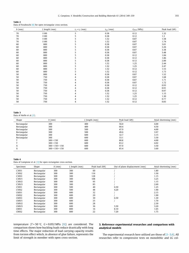
Table 2Data of Foraboschi [6] for open rectangular cross-section.
b (mm) L length (mm) t1 = t2 (mm) tint (mm) GPVB (MPa) Peak load (kN)
G. Campione, V. Rondello / Construction and Building Materials 61 (2014) 349–359 355
temperature (T = 50 �C, G = 0.052 MPa [9]) are considered. Thecomparison shows how buckling loads reduce drastically with longtime effects. The major reduction of load carrying capacity resultsfrom torsion effect which, in absence of glue failure, represents thelimit of strength in member with open cross-section.
3. Reference experimental researches and comparison withanalytical models
The experimental research here utilized are those of [1–3,6]. Allresearches refer to compressive tests on monolithic and LG col-
Table 5Data of Campione et al. [3] for open T cross-section.
Specimen Shape b (mm) L length (mm) Peak load (kN) Axial shortening (mm)
T60S1 T 300 + 150 600 231 4.26T60S2 T 300 + 150 600 154 4.58T60U1 T 300 + 150 600 231 2.37T60U2 T 300 + 150 600 200 2.40T80S1 T 300 + 150 800 208 3.70T80S2 T 300 + 150 800 123 2.84T80U1 T 300 + 150 800 224 3.42T80U2 T 300 + 150 800 200 3.73T100S1 T 300 + 150 1000 214 2.40T100S2 T 300 + 150 1000 193 2.38T100U1 T 300 + 150 1000 141 1.92T100U2 T 300 + 150 1000 146 1.49
Table 6Data of Campione et al. [3] for open X cross-section.
1 Square 1000 110 10.002 Double web 1000 93 12.503 H profile 1000 53 11.504 Star 1000 85 9.805 X 1000 83 13.00
0
1
2
3
4
5
6
0 5 10 15 20 25 30n. specimen
P (k
N)
Nc (Walfen and Bennison, 1987) - Eq.(13)
Nabs - Eq.(6)
Nfull - Eq.(7)
Nc (Amadio and Bedon, 2011) - Eq. (1)
Foraboschi (2009)
Fig. 7. Analytical and theoretical evaluation of critical load for data of Foraboschi[6].
356 G. Campione, V. Rondello / Construction and Building Materials 61 (2014) 349–359
umns and they also refer to compressive tests on columns havingdifferent shape of transverse cross-sections and different length.
Ref. [6] tested in compression specimens manufactured withseveral typologies of laminated glass columns, which in some caseswas made up of two sheets of float glass with different thicknessconnected by a polyvinylbutiral (PVB) film having different thick-ness. Geometrical and mechanical properties of specimens areshown in Table 2.
Ref. [2] tested in compression specimens manufactured withlaminated glass, which was made up of two sheets of float glasswith a thickness of 4 mm connected by a PVB film having a thick-ness equal to 1.00 mm. The whole thickness was 9.00 mm(4 + 1 + 4). Geometrical and mechanical properties of specimensare shown in Table 3.
Ref. [3] tested glass columns and also columns with T-shaped orX-shaped cross-section. The columns were assembled with a mainpanel having a width of 300 mm and one (T-shaped section) or two(X-shaped section) orthogonally disposed columns with side150 mm. Single columns had width 300 mm, thickness 9.52 mmand height equal to 300, 400, 500 and 600 mm, while for columnsit was equal to 600, 800 and 1000 mm. Pair of specimens weretested for each kind (series and geometry). Geometrical andmechanical properties of specimens are shown in Table 4–6.Although specimens are stocky they are useful for understandingphenomenon related to torsional effects in open cross-sectionbeing flexural buckling phenomenon not important for this rangeof length investigated. Further studies will be addressed to exam-ine slender specimens to included flexural buckling phenomenon.
Ref. [1] tested in compression columns having length 1000 mmand cross-section shown in Fig. 1. Glass columns were monolithiccolumns of thickness 8 mm. Geometrical and mechanical proper-ties of specimens are shown in Table 7.
In all tables load carrying capacity with corresponding axialshortening values are given; moreover, when available, displace-ments out of plane are given in Table 7.
G. Campione, V. Rondello / Construction and Building Materials 61 (2014) 349–359 357
Fig. 7 gives the load carrying capacity of specimens tested in [6]and also the analytical prediction with the different models consid-ered. Analytical results were generated with Gint values given by[6] and shown in Table 2. The comparison shows that the modelsof [8] and [13] give the best prediction of experimental resultsand highlight the role of the thickness of PVB and its shear modu-lus. The case of full connection and absence of connection give theupper and the lower limits of critical load.
Fig. 8 shows the variation of critical load deduced with theabove mentioned models with the variation of length of specimens.In the same graphs also experimental values in Tables 2 and 3(rectangular cross-section) are given. Analytical results were gen-erated assuming for Gint a value of 8 MPa (which is a possible valuefor short testing time of few seconds) and a temperature of 20 �C.
Fig. 8. Variation of critical load with length
Fig. 9. Variation of critical flexural load wi
The comparison shows that all models presented, with exceptionof full connections, are conservative and the model of [13] givesthe best prediction of data. Therefore, the approach followed by[10] for compressed glass columns appears appropriate.
Figs. 9 and 10 show the strength variation of critical load for col-umns with X and T transverse cross-section with the length in-creases. Also data given in Table 5 and 6 are shown. Flexuralbuckling, local buckling and torsional buckling strength predic-tions are given in the same graph. Also strength previsions relativeto glue failure are given.
Comparison shows that load carrying capacity is that of the con-nection failure and in the case of T and X cross-section it value isvery close to torsional buckling failure. Glue failure was calculatedassuming for shear strength both values of 12 and 18 MPa as
variation for rectangular cross-section.
th length variation for X cross-section.
Fig. 10. Variation of critical flexural load with length variation for T cross-section.
358 G. Campione, V. Rondello / Construction and Building Materials 61 (2014) 349–359
suggested in [10]. Further studies will be addressed to examine thestrength of glued section though delamination tests to validate val-ues suggested in [10] and also to examine cases of shear an normalstresses (mode I and mode II according to fracture mechanics ap-proach) occurring in real cases and reduction the shear strengthdetermine considering only shear stresses.
In the graphs of Figs. 9 and 10 the strength variation of columnsfor overall buckling out of the plane is not represented because outof the range for the length of the columns here examined. Torsionaleffects and glued failure in the connected section are the main phe-nomenon governing rupture. In the case of T sections torsional ef-fects are more important due to the area and of the geometry ofcross-section (smaller that the X cross-section). To increase theload carrying capacity could be suitable introduce some stiffeners(not object of this research) as shown in Fig. 2. Also to increasethe shear strength of connections could be suitable add longitudi-nal stiffeners in the connected section such as observed in Fig. 2.
For experimental point of view analytical results found confir-mation such as possible to observed for Fig. 11 that shows modeof failure observed in [3] at peak load. Glue rupture in the
glue failure
flexural buckling
Fig. 11. Failure modes observed in columns with T a
connected sections and torsional and local buckling phenomenonare main causes of failure.
In the case of Ouwerkerk [1] the analytical prediction of loadcarrying capacity related to failure of connection shows peak loadsof 96 kN for X, and H cross-section and of 192 kN for square, doubleweb or star cross-sections. These values are close to experimentaldata for double web and X cross-section, while in other cases areunsafe. Analytical values predicted by [1] with detailed nonlinearfinite element analyses are unsafe. As observed in [1] these differ-ences are due to several factors not included in the numerical mod-el: defects in the edge of glass reducing strength of material; notperfect connection in the glue section; and all aspects very difficultto take into account in a simple manner.
4. Conclusions
In this paper, the effects of the transverse cross-section shape(rectangular, X and T) and glued connections between single LGcolumns on the load carrying capacity of glass columns areanalyzed.
glue failure
torsional buckling
nd X cross-section tested in Campione et al. [3].
G. Campione, V. Rondello / Construction and Building Materials 61 (2014) 349–359 359
Experimental results available in the literature referred to com-pressive tests on glass columns with different lengths and differentcross-sections (rectangular columns or beam-like elements (due totheir b/L ratio), T and X shape) are considered for the verification ofthe existing analytical models.
For the range of variables analyzed the following conclusionscan be drawn:
� The buckling strength of LG columns can be predicted accu-rately with simple analytical models available in theliterature;
� The critical load of single columns reduces significantly withthe length of the columns and the range of available com-mercial thicknesses (in the range between 4 and 19 mmwith 25 mm special applications 9 can discourages the useof single columns for the realization of real scale glasscolumns;
� Open cross-sections with T and X shapes are less sensitive toflexural buckling, and they are mainly affected by localbuckling and torsional buckling effects with reduction inthe load carrying capacity;
� The effective load carrying capacity of glass columns withopen cross-section obtained by gluing single columns isstrongly affected by the glue resistance and local and tor-sional buckling;
� Glued connections result in most of the cases examined theweakest parts of columns.
At this stage of research it emerges that to give more generalconclusions more tests are needed, and it emerges that in design-ing glass columns with open cross-section particular care shouldbe placed on the design of the connection. In this case the predic-tion of the joint strength is very hard to establish also because itdepends on several factor also related to the manufacturing. There-fore, to give safe indication for the design of member with opencross-sections more tests are needed.
It could be more appropriate not considering the effective prop-erties of open cross-sections (with X or T cross-sections) and calcu-late the load carrying capacity referring to the buckling load of theweakest single columns or beam-like elements (due to their b/L ra-tio). The effective shape of the transverse cross-section could rep-resent a strength reserve and could be related mainly to aestheticaspects. Finally, further studies could be addressed to examine the
effects of strengthening technique of the glued sections such as theuse of stiffeners such as transverse diagrams) to increase the stiff-ness of the cross-section and to increases the glued surface reduc-ing the shear stressed along the connection.
References
[1] Ouwerkerk E. Glass columns: a fundamental study to slender glass columnsassembled from rectangular monolithic flat glass plates under compression asa basis to design a structural glass column for a pavilion. Master of Scienceprogram of Civil Engineering at the Delft University of Technology. Faculty ofCivil Engineering and Geosciences; 2011. p. 230.
[2] Aiello S, Campione G, Minafò G, Scibilia N. Compressive behaviour of laminatedstructural glass members. Eng Struct 2011;2011(33):3402–8.
[3] Campione G, Di Paola M, Minafò G. Laminated glass members in compression:experiments and modeling. ASCE Struct Eng 2013. http://dx.doi.org/10.1061/(ASCE)ST.1943-541X.0000827.
[4] Belis J, Mocibob D, Luible A, Vandebroek M. On the size and shape of initial outof-plane curvatures in structural glass components. Constr Build Mater2011;25:2700–12.
[5] Luible A, Crisinel M. Buckling design of glass elements under compression. In:Proceedings of the international symposium on the application of architecturalglass. M}unich; 2004.
[6] Foraboschi P. Laminated glass columns. Struct Eng 2009;87(18):20–6.[7] Amadio C, Bedon C. Buckling of laminated glass elements in out-of-plane
bending. Eng Struct 2010;32(11):3780–8.[8] Amadio C, Bedon C. Buckling of laminated glass elements in compression. ASCE
J Struct Eng 2010;137(8):803–10.[9] Bedon C, Amadio C. Buckling of flat laminated glass panels under in-plane
compression or shear. Eng Struct 2012;36:185–97.[10] CNR-DT 210/2012 Instructions for Design, Execution and Control of Buildings
with Structural Elements Glass, ROMA–CNR 5 luglio; 2012. p. 359 [onlyavailable in Italian].
[11] Comité Européen de Normalisation (CEN), prEN 13474:2007, Glass in Building– determination of the strength of glass panes; 2008.
[12] Newmark NM, Siess CP, Viest IM. Test and analysis of composite beams withincomplete interaction. Proc Soc Exp Stress Anal 1951;9:75–92.
[13] Wölfel E. Nachgiebiger Verbund eine Näherungslösung und derennwendungsmöglichkeiten. Stahlbau 1987;6(1987):173–80.
[14] Briccoli Bati S, Ranocchiai G, Reale C, Rovero L. Time-dependent behavior oflaminated glass. ASCE J Mater Civil Eng 2010;22(4):389–96.
[15] Bennison SJ, Smith CA, Van Duser A. Structural performance of laminated glassmade with a stiff interlayer. In: Symp. on the use of glass in buildings.Pittsburgh; 2002.
[16] Galuppi L, Royer-Carfagni G. Effective thickness of laminated glass beams. Newexpression via a variational approach. Eng Struct 2012;38:53–67.
[17] Trahair NS. Strength design of cruciform steel columns. Eng Struct2012;35:307–13.


![UNIVERSITY OF THE BASQUE COUNTRY DETERMINATION OF TRANSVERSE COMPRESSIVE STRENGTH OF LONG FIBER COMPOSITES BY THREE-POINT BENDING OF [90m/0n] LAMINATED.](https://static.documents.pub/doc/80x56/56649d2e5503460f94a05143/university-of-the-basque-country-determination-of-transverse-compressive-strength.jpg)


