Page 1
'
&
$
%
EFFECTS OF SPREADING IN OFDM-BASED
SYSTEMS
Thesis submitted in partial fulfillment
of the requirements for the degree of
Bachelor of Technology
in
Electronics and Electrical Communication Engineering
by
Varun Bedi(07EC1026)
Under the guidance of
Dr. Suvra Sekhar Das
Indian Institute of Technology, Kharagpur
May, 2011
Page 2
Indian Institute of TechnologyKharagpur
Certificate
This is to certify that the thesis entitled ”Effects of Spreading in OFDM-based Sys-
tems” is a bona fide record of work carried out byVarun Bedi, under my supervision
and guidance, for the partial fulfillment of the requirements for the award of the degree
of Bachelor of Technology (Honors)in Electronics and Electrical Communication Engi-
neering at the Indian Institute of Technology, Kharagpur. The thesis has fulfilled all the
requirements as per the regulations of the institute and in my opinion reached the standard
for submission
Dr. Suvra Sekhar Das
Assistant Professor
G. S. Sanyal School of Telecommunications,
Indian Institute of Technology, Kharagpur.
Place: IIT Kharagpur
Date: May 2011
Page 3
Acknowledgement
I am greatly indebted to my project supervisor Prof. Suvra Sekhar Das for his invaluable
guidance and encouragement throughout the course of this project. I would like to takethis opportunity to express my sincere and profound gratitude to him.
I would also like to gratefully acknowledge the suggestionsand discussions received
from Priyangshu, Arun, Narendra, Swathi, Prabhu, Myna, Sawan, Praveen, Jayant, Rohit,Raghvendra and Shanshank whenever I had any doubt.
My sincere thanks also go to all the faculty of E & ECE for theirkind co-operation in
all spheres during my project work. I would also like to thankall others whose direct orindirect help has benefited me during my stay at IIT Kharagpur.
Furthermore, I would like to thank all other friends and fellow students of IIT Kharagpur
and particularly my E&ECE mates for sparing great time throughout my B.Tech and verygood support I received from them during my stay.
Last but not the least, I thank my parents and all my family members for their support
and motivation they have provided throughout my project.
Varun Bedi
ii
Page 4
Abstract
OFDM-based systems has shown good performance recently in terms of high spectral effi-
ciency and also robustness against multipath fading. However, they pose a serious problem
of high Peak to Average Power Ratio (PAPR). The operation of Spreading, using orthog-
onal Spreading codes, is used to obtain similar throughput advantage and robustness in
CDMA systems. To overcome the shortcoming of OFDM-based systems, various attempts
have been made to manage the high PAPR, without losing the benefits of OFDM. One of
them is introducing Spreading in OFDM-based Systems. Spread-spectrum OFDMA is one
such technique where we combine some benefits of both OFDMA and CDMA systems.
In this work, we first extend the concept of Overloading, already present in the downlink
of CDMA2000, to Spread Spectrum OFDMA, and compare the effects of doing so. Next,
we extend the Overloading concept to Underloading, where itis intended to investigate the
case when less number of users than the capaciy limit are present in the system. Hence, Un-
derloaded Spread-spectrum OFDMA performance has been evaluated next. This scheme
is particularly relevant to the femtocell scenario, where the number of users is less but the
throughput requirement may be more.
In the later part of the work, we have tried changing the interleaving depth, and to
investigate its effect on various flavors of Spread SpectrumOFDMA. In the last part, we
takenMCSdata from a VoIP simulation, and modelled our underloaded SS-OFDMA to the
partial PRB usage required here. We analyze the performanceof our scheme, and compare
it with other schemes applied to the same data.
iii
Page 5
Contents
Acknowledgement ii
Abstract iii
1 Introduction 1
1.1 Background. . . . . . . . . . . . . . . . . . . . . . . . . . . . . . . . . 1
1.2 Motivation. . . . . . . . . . . . . . . . . . . . . . . . . . . . . . . . . . 2
1.3 Access Techniques. . . . . . . . . . . . . . . . . . . . . . . . . . . . . 2
1.4 Problem Definition . . . . . . . . . . . . . . . . . . . . . . . . . . . . . 3
1.5 Work Done . . . . . . . . . . . . . . . . . . . . . . . . . . . . . . . . . 3
2 Radio Access Techniques 5
2.1 Fundamentals of RATs. . . . . . . . . . . . . . . . . . . . . . . . . . . 5
2.2 Performance Requirements for IMT-A systems. . . . . . . . . . . . . . 5
2.3 Multiple Access Techniques - An Overview. . . . . . . . . . . . . . . . 7
2.4 OFDMA . . . . . . . . . . . . . . . . . . . . . . . . . . . . . . . . . . . 10
2.5 Spread Spectrum OFDMA. . . . . . . . . . . . . . . . . . . . . . . . . 11
2.5.1 MC-SS-MA. . . . . . . . . . . . . . . . . . . . . . . . . . . . . 11
2.5.2 SC-FDMA . . . . . . . . . . . . . . . . . . . . . . . . . . . . . 11
3 Overloaded Spread Spectrum OFDMA 13
3.1 Introduction. . . . . . . . . . . . . . . . . . . . . . . . . . . . . . . . . 14
3.2 System Description. . . . . . . . . . . . . . . . . . . . . . . . . . . . . 14
3.2.1 Transceiver Description. . . . . . . . . . . . . . . . . . . . . . 14
3.2.2 System Block-Diagram for UL-Transmission. . . . . . . . . . . 16
3.2.3 System Block-Diagram for DL-Transmission. . . . . . . . . . . 16
3.3 Multi-Stage Detector. . . . . . . . . . . . . . . . . . . . . . . . . . . . 19
3.4 Analytical Model . . . . . . . . . . . . . . . . . . . . . . . . . . . . . . 20
3.5 Code Selection. . . . . . . . . . . . . . . . . . . . . . . . . . . . . . . 22
iv
Page 6
CONTENTS CONTENTS
4 Underloaded Spread Spectrum OFDMA 25
4.1 Introduction. . . . . . . . . . . . . . . . . . . . . . . . . . . . . . . . . 25
4.2 Transceiver Description. . . . . . . . . . . . . . . . . . . . . . . . . . . 25
5 The Interleaving operation 27
5.1 Introduction. . . . . . . . . . . . . . . . . . . . . . . . . . . . . . . . . 27
5.2 Overloading. . . . . . . . . . . . . . . . . . . . . . . . . . . . . . . . . 28
5.3 Underloading. . . . . . . . . . . . . . . . . . . . . . . . . . . . . . . . 31
6 SDIC in Overloaded SS-OFDMA 33
6.1 Introduction. . . . . . . . . . . . . . . . . . . . . . . . . . . . . . . . . 33
6.2 Measures of Confidence. . . . . . . . . . . . . . . . . . . . . . . . . . 33
6.2.1 Exact LLR . . . . . . . . . . . . . . . . . . . . . . . . . . . . . 34
6.2.2 Approximate LLR . . . . . . . . . . . . . . . . . . . . . . . . . 34
6.3 SDIC Algorithm. . . . . . . . . . . . . . . . . . . . . . . . . . . . . . . 34
7 Results - Overloading and Underloading 36
7.1 Overloaded SS-OFDMA with HDIC receiver. . . . . . . . . . . . . . . 36
7.1.1 Low Interleaving. . . . . . . . . . . . . . . . . . . . . . . . . . 36
7.1.2 More interleaving. . . . . . . . . . . . . . . . . . . . . . . . . . 39
7.1.3 Comparison of BPSK 100% overload with QPSK 0% overload. . 39
7.2 Overloaded SS-OFDMA with SDIC receiver. . . . . . . . . . . . . . . . 44
7.2.1 Low Interleaving. . . . . . . . . . . . . . . . . . . . . . . . . . 44
7.2.2 More interleaving. . . . . . . . . . . . . . . . . . . . . . . . . . 44
7.2.3 Comparison of BPSK 100% overload with QPSK 0% overload. . 49
7.3 Underloaded SS-OFDMA. . . . . . . . . . . . . . . . . . . . . . . . . 51
7.3.1 Low Interleaving. . . . . . . . . . . . . . . . . . . . . . . . . . 51
7.3.2 More Interleaving. . . . . . . . . . . . . . . . . . . . . . . . . . 51
8 Underloaded SS-OFDMA for Dynamic VoIP data 57
8.1 OFDMA - Concept of PRB. . . . . . . . . . . . . . . . . . . . . . . . . 57
8.2 Applying Underloaded SS-OFDMA. . . . . . . . . . . . . . . . . . . . 58
8.3 BER Results. . . . . . . . . . . . . . . . . . . . . . . . . . . . . . . . . 59
8.3.1 AWGN Channel - Without Spreading. . . . . . . . . . . . . . . 59
8.3.2 Rayleigh Channel - Without Spreading. . . . . . . . . . . . . . 59
8.3.3 Rayleigh Channel - With Spreading. . . . . . . . . . . . . . . . 63
8.3.4 Rayleigh Channel - With Variable Spreading. . . . . . . . . . . 63
v
Page 7
CONTENTS CONTENTS
9 Conclusions and Future work 66
9.1 Conclusion . . . . . . . . . . . . . . . . . . . . . . . . . . . . . . . . . 66
9.2 Future Work. . . . . . . . . . . . . . . . . . . . . . . . . . . . . . . . . 67
Appendices 68
.1 PAPR performance results. . . . . . . . . . . . . . . . . . . . . . . . . 69
.1.1 Conclusion . . . . . . . . . . . . . . . . . . . . . . . . . . . . . 69
List of Abbreviations 72
Bibliography 74
vi
Page 8
List of Figures
2.1 Transmitter-Receiver Block Diagram of OFDMA. . . . . . . . . . . . . 10
2.2 Transmitter-Receiver Block Diagram of MC-SS-MA. . . . . . . . . . . 12
3.1 Transmitter Block Diagram for Overloaded OFDM. . . . . . . . . . . . 15
3.2 Receiver Block Diagram for Overloaded OFDM. . . . . . . . . . . . . . 15
3.3 UL-Transmission system Block Diagram for Overloaded SS-OFDMA . . 17
3.4 UL-Reception system Block Diagram for Overloaded SS-OFDMA . . . . 17
3.5 DL-Transmission system Block Diagram for Overloaded SS-OFDMA . . 18
3.6 DL-Reception system Block Diagram for Overloaded SS-OFDMA . . . . 19
3.7 Iterative Multi-Stage Detector Algorithm. . . . . . . . . . . . . . . . . . 20
4.1 Downlink Tx Block diagram from Base-station in Low interleaving case. 26
4.2 Downlink Rx Block diagram at each-user in Low interleaving case. . . . 26
5.1 Downlink Tx Block diagram from Base-station in Low interleaving case. 28
5.2 Downlink Rx Block diagram at each-user in Low interleaving case for
Overloading. . . . . . . . . . . . . . . . . . . . . . . . . . . . . . . . . 29
5.3 Downlink Tx Block diagram from Base-station in High interleaving case. 30
5.4 Downlink Rx Block diagram at each-user in High interleaving case. . . . 30
5.5 SS-OFDMA Small Interleaver Transmitter Block Diagram. . . . . . . . 31
5.6 SS-OFDMA Small Interleaver Receiver Block Diagram. . . . . . . . . . 31
5.7 SS-OFDMA Small Interleaver Transmitter Block Diagram. . . . . . . . 32
5.8 SS-OFDMA Small Interleaver Receiver Block Diagram. . . . . . . . . . 32
6.1 The SDIC Algorithm for 2 bits/symbols case. . . . . . . . . . . . . . . . 35
7.1 BER performance of Overloaded SS-OFDMA for different modulation in
Low interleaving Indoor, with HDIC receiver. . . . . . . . . . . . . . . 37
7.2 BER performance of Overloaded SS-OFDMA for different modulation in
Low interleaving Outdoor, with HDIC receiver. . . . . . . . . . . . . . 38
vii
Page 9
LIST OF FIGURES LIST OF FIGURES
7.3 BER performance of Overloaded SS-OFDMA for different modulation in
More interleaving Indoor, with HDIC receiver. . . . . . . . . . . . . . . 40
7.4 BER performance of Overloaded SS-OFDMA for different modulation in
More interleaving Outdoor, with HDIC receiver. . . . . . . . . . . . . . 41
7.5 BER performance of Overloaded SS-OFDMA for BPSK 100 percent Over-
load with QPSK 0 percent overload Low interleaving case, with HDIC
receiver . . . . . . . . . . . . . . . . . . . . . . . . . . . . . . . . . . . 42
7.6 BER performance of Overloaded SS-OFDMA for BPSK 100 percent Over-
load with QPSK 0 percent overload More interleaving case, with HDIC
receiver . . . . . . . . . . . . . . . . . . . . . . . . . . . . . . . . . . . 43
7.7 BER performance of Overloaded SS-OFDMA for different modulation in
Low interleaving Indoor, with SDIC receiver. . . . . . . . . . . . . . . . 45
7.8 BER performance of Overloaded SS-OFDMA for different modulation in
Low interleaving Outdoor, with SDIC receiver. . . . . . . . . . . . . . . 46
7.9 BER performance of Overloaded SS-OFDMA for different modulation in
More interleaving Indoor, with SDIC receiver. . . . . . . . . . . . . . . 47
7.10 BER performance of Overloaded SS-OFDMA for different modulation in
More interleaving Outdoor, with SDIC receiver. . . . . . . . . . . . . . 48
7.11 BER performance of Overloaded SS-OFDMA for BPSK 100 percent Over-
load with QPSK 0 percent overload Low interleaving case, with SDIC re-
ceiver . . . . . . . . . . . . . . . . . . . . . . . . . . . . . . . . . . . . 49
7.12 BER performance of Overloaded SS-OFDMA for BPSK 100 percent Over-
load with QPSK 0 percent overload More interleaving case, with SDIC
receiver . . . . . . . . . . . . . . . . . . . . . . . . . . . . . . . . . . . 50
7.13 Comparison of BER performance of Underloaded SS-OFDMAfor differ-
ent modulation in Low interleaving indoor case. . . . . . . . . . . . . . 52
7.14 Comparison of BER performance of Underloaded SS-OFDMAfor differ-
ent modulation in Low interleaving Outdoor case. . . . . . . . . . . . . 53
7.15 Comparison of BER performance of Underloaded SS-OFDMAfor differ-
ent modulation in More interleaving indoor case. . . . . . . . . . . . . . 54
7.16 Comparison of BER performance of Underloaded SS-OFDMAfor differ-
ent modulation in More interleaving Outdoor case. . . . . . . . . . . . . 55
8.1 Available Downlink Bandwidth is divided into PRBs. . . . . . . . . . . 57
8.2 PDF of number of PRBs using a modulation scheme. . . . . . . . . . . 58
8.3 BER performance of OFDMA for Dynamic VoIP data under AWGNChannel 60
viii
Page 10
LIST OF FIGURES LIST OF FIGURES
8.4 BER performance of OFDMA for Dynamic VoIP data under Rayleigh
Channel . . . . . . . . . . . . . . . . . . . . . . . . . . . . . . . . . . . 61
8.5 BER performance of OFDMA - finding performance equivalent of Full-
loaded case. . . . . . . . . . . . . . . . . . . . . . . . . . . . . . . . . 62
8.6 BER performance of SS-OFDMA for Dynamic VoIP data under Rayleigh
Channel . . . . . . . . . . . . . . . . . . . . . . . . . . . . . . . . . . . 64
8.7 BER performance of SS-OFDMA for Dynamic VoIP data under Rayleigh
Channel, with Variable Spreading. . . . . . . . . . . . . . . . . . . . . 65
1 Comparison of PAPR performance of SC-FDMA with OFDMA for differ-
ent modulation . . . . . . . . . . . . . . . . . . . . . . . . . . . . . . . 69
2 Comparison of PAPR performance of partial PRB cases for SG 12 and
variable SG with OFDMA . . . . . . . . . . . . . . . . . . . . . . . . . 70
ix
Page 11
List of Tables
2.1 Cell Spectral Efficiency. . . . . . . . . . . . . . . . . . . . . . . . . . . 6
2.2 Cell Edge Spectral Efficiency. . . . . . . . . . . . . . . . . . . . . . . . 6
2.3 Peak Data Rate for IMT-A. . . . . . . . . . . . . . . . . . . . . . . . . 7
2.4 Supported environment and mobility types. . . . . . . . . . . . . . . . . 7
2.5 Summary of Multiple Access Techniques. . . . . . . . . . . . . . . . . 9
3.1 Values of Set Cross Correlation. . . . . . . . . . . . . . . . . . . . . . . 24
x
Page 12
1Introduction
1.1 Background
Since the 1990’s, the cellular industry has seen a massive growth in the number of mobile
phone users and their requirements. As a result, there have been constant attempts to im-
prove the performance of cellular systems (data rate, spectral efficiency, and throughput),
while minimizing the costs incurred.
Wireless communication started with the analog1st generation serviceAMPS. The2nd
Generation (2G) GSM and CDMA were digital in nature and used the multiple access
schemes Time Division Multiple Access (TDMA) and Code Division Multiple Access
(CDMA), along with Frequency Division Multiple Access (FDMA). Data services were
later introduced inGPRSandEDGE. 3rd Generation (3G) such asUMTS andW-CDMA
were the first to see data rates upto 2 Mbps and beyond. Finally, in the Beyond 3rd
Generation (B3G) services,LTE has adopted Orthogonal Frequency Division Multiplexing
(OFDM), the access technology dominating the latest evolutions of all mobile radio stan-
dards [1].
1
Page 13
Motivation Introduction
1.2 Motivation
4th Generation (4G) is the fourth generation of cellular wireless standards. In 2008, the
International Telecommunication Union (ITU) released a set of requirements for any4G
technique by the name of International Mobile Telecommunications-Advanced (IMT-A ).
The key Radio Access Technologies that are a part of different upcoming mobile radio stan-
dards for IMT-A are Orthogonal Frequency Division MultipleAccess (OFDMA), Code
Division Multiple Access (CDMA) and Space Division Multiple Access (SDMA). Also,
Single Carrier/Multi-Carrier operation as well as combination of these technologies can
be considered to be an effective Radio Access Technique (RAT) which can satisfy the
requirements ofIMT-A [2].
The 3GPPhas also created a formal Study Item with the specific aim of evolving the
3GPPradio access technology into Long Term Evolution - Advanced(LTE-A), a proposed
4G mobile radio standard, to ensure competitiveness. Some of the main objectives were in-
creased data rates, greater flexibility of spectrum usage and reasonable power consumption
for the mobile terminal.
1.3 Access Techniques
The 3G schemes started off based onCDMA technology and its different forms. Later
standards like Long Term Evolution (LTE) were based onOFDMA technology, which
is considered a better technique for mitigating Multipath Fading effects and Inter Carrier
Interference (ICI), effects that are more adverse in high-mobility scenariosof the IMT-A
requirements.
The technique Orthogonal Frequency Division Multiplexing(OFDM) is a type of Fre-
quency Division Multiplexing (FDM), where all the carriers allocated to users are orthog-
onal to each other. Because of the orthogonality, OFDM mitigatesICI and hence improves
the system performance. This orthogonality can be effectively achieved by using Inverse
Fast Fourier Transform (IFFT) and Fast Fourier Transform (FFT) blocks, instead of a se-
ries of upconverters and downconverters, leading to drastic reduction in the Trasceiver
complexity. OFDM also uses a Guard Period at the end of each OFDM symbol which is
used to check Inter Symbol Interference (ISI) due to Multipath effect. OFDMA enabled
LTE to enhance data rate to a maximum of 100 Mbps in downlink and 50Mbps in uplink.
Howeverm, one of the main disadvantage ofOFDM is its high Peak to Average Power
2
Page 14
Problem Definition Introduction
Ratio (PAPR), which introduces non-linearities in the power amplifier at the transmitter
and hence causes more distortions in received signal at userterminal.
For the Uplink,LTE uses single Single Carrier-Frequency Division Multiple Access
(SC-FDMA). SC-FDMA uses Discrete Fourier Transform (DFT)-Spreading before map-
ping data symbols on the carrier. This reduces the PAPR of thetransmitted signal, as one
symbol itself is spread over multiple carriers. This reduces power requirement at the user
terminal and leads to saving of mobile battery life. Also, due to the nature of SC-FDMA,
there is some scope on increasing the Spectral Efficiency andhence the average Through-
put of the system in Uplink.
1.4 Problem Definition
Increasing Capacity or Spectral Efficiency of OFDM-based access techniques is a big chal-
lenge to Telecommunication engineers at present. With thisrespect, the main objective of
this project has been to develop a new Radio Access Technique(RAT) that offers better
Capacity or Spectral Efficiency performance, or has a lower PAPR of the transmitted sig-
nal, and meets the ever-increasing demand for data rates of users to a greater extent than
existing techniques.
OFDMA has been widely accepted as a RAT for the future, due to its strong benefits.
In this work, we concentrated on ways to increase capacity ofOFDMA. One way to do
this is to introduce Spreading in the scheme, which reduces the PAPR and gives a Soft
Capacity limit to the scheme. This work investigates such techniques, and evaluates the
performance gain obtained in each case.
1.5 Work Done
Initially a literature survey was carried out to find out the benefits and shortfalls of different
Radio Access Techniques (RATs). This is presented in Chapter 2.
Next, we talk about the extending the concept of Overloaded CDMA into OFDMA
based systems, in what is called Overloaded Spread Spectrum-Orthogonal Frequency Divi-
sion Multiple Access (SS-OFDMA). Chapter 3 presents the theoretical idea of this scheme.
In Chapter 4, we present the theory for extending concepts ofUnderloading in CDMA
to SS-OFDMA.
3
Page 15
Work Done Introduction
Chapter 5 presents the theory behind the Interleaver block of the transceiver. We have
investigated the effects of changing the Interleaver depth, in each of the above cases.
Chapter 6 presents a Soft Decision Interference Cancellation (SDIC) scheme for the
Receiver, to improve the performance of Overloaded SS-OFDMA.
In Chapter 7, we have analyzed Underloaded SS-OFDMA for a simulated picture of
Modulation levels in OFDMA PRBs in VoIP transmission.
Finally, in Chapter 8, we present the results for each of the cases. Evaluation of the pro-
posed schemes has been carried out with respect to its Bit Error Rate (BER), Throughput
and PAPR performances.
4
Page 16
2Radio Access Techniques
2.1 Fundamentals of RATs
Radio Access Techniques (RATs) are the backbone of any Wireless Communication sys-
tem, enabling multiple users to share limited network resources, such as bandwidth, effi-
ciently. Design of newRATs must take into account different kinds of wireless channel
conditions, along with the mobility and the traffic conditions. Any new RAT being de-
signed for 4G cellular systems must meet with the following IMT-A requirements issued
by ITU-R.
2.2 Performance Requirements for IMT-A systems
Requirements presented below give a brief overview of the entire document [3].
1. Cell Spectral Efficiency
It’s the aggregate throughput of all the users in an Service Data Unit (SDU) divided
by Channel Band Width (BW) and divided by number of cells.
n =
∑N
i=1 |xi|
(T ∗ w ∗ M)(2.1)
5
Page 17
Performance Requirements for IMT-A systems Radio Access Techniques
where, T: Time over which the Bits are to be transmitted
w: Channel BW
M: no. of Cells
Table 2.1shows the Cell Spectral Efficiency requirements for different environ-
mental conditions.
Table 2.1: Cell Spectral Efficiency
Test Environment Downlink(bits/sec/Hz/Cell)
Uplink(bits/sec/Hz/Cell)
Indoor 3 2.25Microcellular 2.6 1.8Base Coverage Urban 1.5 1.4High Speed 1.1 0.7
2. Bandwidth
The RAT should be able to scale BW up to and including 40 MHz.
It also suggests that operation can be extended up to wider BWof 100 MHz, and the
RAT should be able to handle this.
3. Cell edge user spectral efficiency
It is the 5% point of the Cumulative Distribution Function (CDF) of Normalized
User Throughput. Table2.2 shows the cell edge spectral efficiency for different
environments.
Table 2.2: Cell Edge Spectral Efficiency
Test Environment Downlink(bits/sec/Hz/Cell)
Uplink(bits/sec/Hz/Cell)
Indoor 0.1 0.07Microcellular 0.075 0.05Base Coverage Urban 0.06 0.03High Speed 0.04 0.015
4. Latency
C-Plane (Transition time from Idle state to Active state): 100msec
U-Plane (Transport delay from IP layer of Base station to IP layer of terminal): 10m-
sec
6
Page 18
Multiple Access Techniques - An Overview Radio Access Techniques
5. Peak Data Rates
Table2.3shows peak Data Rate requirements of IMT-Advanced.
Table 2.3: Peak Data Rate for IMT-A
- Bandwidth DatarateDL-Peak 40MHz 600MbpsDL-Peak 100MHz 1.5GbpsUL-Peak 40MHz 270MbpsUL-Peak 100MHz 675Mbps
6. Mobility class and Test environment supported
Table2.4shows test environment supporting types of mobility (notation: Y).
Table 2.4: Supported environment and mobility types
Mobility \(Test Envi-ronment)
Stationary(0 Km/Hr)
Pedestrian(0-10 Km/Hr)
Vehicular(10-120Km/Hr)
Stationary(120-350Km/Hr)
Indoor Y Y - -Microcellular Y Y Y(up to 30 Km/Hr) -Base coverage Urban Y Y Y -High Speed - - Y Y
7. Handover
Handover interruption time is defined as time over which userterminal can’t ex-
change user plane packet with any of the serving base station. For different condi-
tions, Hand over interruption time is given below.
Intra frequency : 27.5 msec
Inter frequency:
(a) Within same Spectrum Band: 40 msec
(b) Between different Spectrum Band: 60 Msec
2.3 Multiple Access Techniques - An Overview
In the early stages of modern communication, scarce BW was shared between multiple
users with separate frequency channels without significantinterference among the users.
This is the simplest of way of having multiple access scheme among users and is referred
to as Frequency Division Multiple Access (FDMA).
7
Page 19
Multiple Access Techniques - An Overview Radio Access Techniques
With the invent of digital technology, many users were assigned time slots on the same
frequency channel instead of a separate frequency channel for each user. This kind of
technique is called Time Division Multiple Access (TDMA). Users can send bursts of data
in its alloted time slot and this process is repeated periodically in each frame. This required
additional transceiver circuitry to have Time Synchronization in the system.
Now, Frequency Division Multiple Access (FDMA) and Time Division Multiple Access
(TDMA) techniques have their limits of capacity that they can support(i.e. it supports only
a fixed number of users as number of time slots or frequency channels available are fixed).
A combination ofTDMA andFDMA is used to enhance the capacity of the system which
gave rise to Global System for Mobile communication (GSM), the global standard in 2G
and 2.5G.
Another technique calledCDMA was efficient compared to the earlier two with respect
to Soft Hand over, high BW efficiency and soft capacity limit.It involves allocation of
orthogonal code sequences to each user who are using the common frequency resource at
the same time, to faciliate multiple access. FurtherCDMA is also being used in its different
forms such asMC-CDMA [4], MC-DS-CDMA [4], OFDM-CDMA [5]. However, there
are many problems faced by the currently available CDMA Technology [6].
Table2.5 gives a brief evaluation, description, pros and cons of existing of multiple
access schemes [7].
8
Page 20
Multiple Access Techniques - An Overview Radio Access Techniques
Table 2.5: Summary of Multiple Access Techniques
Approach SDMA TDMA FDMA CDMAIdea Segment space
into cells orsectors
segment sendingtime into dis-joint time slots
segment sendingfrequency bandsinto disjoint fre-quency channels
Data Spreadover availableSpectrum
Terminal Only One termi-nal can be acti-vated
All terminals areactive but onlyfor a short pe-riod
every termi-nal has itsown frequencyuninterrupted
all the terminalscan be active atthe same placeat the same mo-ment
Signal Sepa-ration
cell structure di-rected antennas
synchronizationin the timedomain
filtering inthe frequencydomain
code along withspecial receiverarchitecture
Advantage very simple, in-creases capacityper sqr.km
easy HO, fullydigital, lowbattery con-sumption
simple, contin-uous transmis-sion and hencelow overhead,robust
flexible, lessfrequencyplanning, softhandover,soft capacity,privacy
Disadvantage Inflexible, an-tennas typicallyfixed
guard spaceneeded, highsynchronizationoverhead, robust
inflexible andmore carrierslead to ICI, highBS cost
complex re-ceiver, needsmore compli-cated powercontrol forsenders, softcapacity limit
Comment only with com-bination withTDMA, FDMA,CDMA useful
can be usedin low delayspread env. withlow mobility
gives frequencyselectivity de-pending onchannel sepa-ration betweenthe users andmaximum delayspread
for large delayspread, receivercomplexityincreases.
9
Page 21
OFDMA Radio Access Techniques
2.4 OFDMA
Along with techniques mentioned above, one of the techniquethat has got immense impor-
tance is OFDMA. The main advantages ofOFDMA over TDMA/CDMA is, its scalability,
uplink orthogonality and the ability to take advantage of the channel frequency selectivity.
Hence, recent wireless standards such as 3GPP-LTE, IEEE-802.16e, and W-LAN (IEEE-
802.11) has considered OFDM as access technique.
OFDM is multiplexing technique that subdivides available bandwidth into several par-
allel sub-streams of reduced datarate and hence each sub-stream is transmitted on orthog-
onal carrier. Fig.2.1 [7] shows transmitter-receiver block diagram of OFDMA system.
Its shows that, serial bit-stream is modulated to symbols which are transmitted in parallel
on each orthogonal carrier. Use of the IFFT ensures orthogonality between the carriers.
Also introduction of Cyclic Prefix (CP) completely eliminates effect ofISI as long as CP
duration is more than the maximum channel delay spread. CP isonly the repetition of few
of the last samples and hence makes the system resistant to fading effect.
At the receiver side, CP number of samples are removed from the receivedOFDMA
symbol. Further a reverse of the process mentioned above starts with IFFT replaced by
Figure 2.1: Transmitter-Receiver Block Diagram of OFDMA
10
Page 22
Spread Spectrum OFDMA Radio Access Techniques
FFT operation and so on. After FFT at the receiver, Frequencydomain equalization is
performed and it is followed by de-mapper. One of the disadvantage of OFDMtechnique
is a high Peak to Average Power Ratio (PAPR).
2.5 Spread Spectrum OFDMA
In this SS-OFDMA, a symbol to be mapped on a carrier is instead spread over spreading
gain amount of carriers. This gives the advantage of frequency diversity and hence even
channel condition is not good for certain carriers, symbol mapped can be decoded easily.
Hence this kind of technique gives benefit of OFDMA and CDMA. Depending on correla-
tion properties, system performance of Spread Spectrum OFDMA varies. Hence, receiver
has to use Multiuser Detection techniques to mitigate interference. On the basis of codes
used for spreading, it can be categorized under following techniques.
2.5.1 MC-SS-MA
This is nothing but Multi Carrier Spread Spectrum Multiple Access (MC-SS-MA). Fig.2.2[7]
shows the block diagram of MC-SS-MA access technique. Symbols before giving to the
IFFT are passed through spreader. Number of symbols at the input of the spreader depends
on the spreading gain of spreading sequences used. This means, for 100% loading of sym-
bols, number of symbols are exactly equal to the spreading gain but for lower loading
factor, number of symbols to be spread are less.
One of the advantage as mentioned before, of this technique is we can get diversity gain
because of the spreading of one symbol over multiple carriers. But, at the receiver, this
technique increases receiver complexities.
2.5.2 SC-FDMA
SC-FDMAis one of the type ofMC-SS-MAtechnique wherein, DFT Spreading used at the
Spreading block in Fig.2.2 [7]. Use of this DFT spreading which are having orthogonal
sequences gains all the advantages of MC-SS-MA along with that reduces PAPR of the
system. SC-FDMA is used as UL access technique for 3GPP-LTE standard. [8] Reason
behind selecting SC-FDMA instead of OFDMA for UL transmission in LTE standard is,
OFDMA is having issue of PAPR because at the output of IFFT, all the carriers get added
constructively resulting large envelope fluctuations. Signal with this high PAPR requires
highly linear power amplifiers to avoid excessive intermodulation distortion. To achieve
11
Page 23
Spread Spectrum OFDMA Radio Access Techniques
Figure 2.2: Transmitter-Receiver Block Diagram of MC-SS-MA
this linearity, amplifiers has to operate with large back offfrom this peak power means it
has to provide large amount of DC power, resulting in less efficiency. It gives significant
burden on portable wireless terminal. Second reason behindselecting SC-FDMA instead
of OFDMA for LTE-UL is Another problem with OFDMA in cellularuplink transmissions
derives from the inevitable offset in frequency referencesamong the different terminals that
transmit simultaneously. Frequency offset destroys the orthogonality of the transmissions,
thus introducing multiple access interference.
There are two techniques of subcarrier mapping for the design of the SC-FDMA scheme.
Localize subcarrier mapping gives good throughput performance compared to Interleaved
subcarrier mapping. But, Interleaved Subcarrier mapping gives good PAPR performance
by 3-7dB. Comparison of SC-FDMA and OFDMA performance resuls is given in [9] and
[10].
12
Page 24
3Overloaded Spread Spectrum OFDMA
In this chapter, we investigate a OFDM-based access technique modified and combined
with CDMA to utilize certain advantages of it. The objective is to investigate and compare
its performance with existing access techniques suggestedin recent standards.
One of the merits of CDMA based techniques is Soft Capacity i.e. it can be overloaded
to get higher capacity, with certain degradation in probability of bit error. Overloading is
a term used in Cellular CDMA technique. Generally, CDMA allocates every sequence of
lengthN to maximumN number of users, i.e.,N = TTc
is the processing gain orSpreading
Gain of CDMA.
where,T : Symbol Duration andTc: Chip Duration
If less thanN number of users are allocated using chip sequence of lengthN , then
system is called anUnderloaded System. In this case, Orthogonality of the codes is not
violated and hence their performance is not affected.
When the number of usersM exceedN , system is said to be anOverloaded System.
So, in this case, it is necessary to assignM number of sequences (M > N). Hence,
the sequences are no more orthogonal and in effect, it increases the Multiple Access
Interference (MAI ). This kind of scheme can be used to increase the System Capacity,
13
Page 25
Introduction Overloaded Spread Spectrum OFDMA
but in effect it makes the system performance worse
In literature, different approaches are described to mitigate this effect of overloading
and hence enable more number of users to share BW simultaneously. Several approaches
includes the use of Multi User Detection (MUD) at Base Station. [11] has shown CDMA
Overloading performance using Iterative Interference Cancelation Receiver. Several ap-
proaches also suggest use of Orthogonal Codes such as Quasi Orthogonal Sequences
(QOS) and Orthogonal Gold (OG) Codes can enhance system performance [12].
3.1 Introduction
Recently, OFDMA based access techniques have been dominantand are suitable for multi-
path environment. For next generation wireless sytems, we can still think about combina-
tion of CDMA and OFDMA. One of this kind of technique which is used in 3GPP-LTE
standard isSC-FDMA [13]. It consists of DFT spreading which enables the Code Divi-
sion Multiplexing of the symbols. This concept of Overloading in CDMA can be extended
further to OFDM based systems to increase the capacity.
This can be possible using different kinds of spreading codes, such asOG Codes or
QOS. These codes must have very little or no performance degradation as compared to
underloaded systems and should possess good correlation properties. Further, it is also
necessary to use a Multi Stage Detector [14] for the additional interference cancelation.
Keeping all this in mind, we need to evaluate this new scheme,and compare it with existing
techniques, for different channel conditions and amounts of Overloading.
3.2 System Description
3.2.1 Transceiver Description
One of the advantages of Overloaded OFDMA is that it increases the capacity of OFDM
system in proportion with the increase in the amount of Overload. Also, Symbols are
spread over carriers equivalent to the amount of spreading gain. So it also brings in ad-
vantage of Diversity Gain. This is because, under deep fade over certain carriers it avoids
the loss of those many number of symbols and hence distributes the fade over all the sym-
bols equally which can be further easily recovered at receiver side. But, this novel Access
technique has to deal with the highPAPRissue as it mainly depends on kind of spreading
sequences we are using [15].
14
Page 26
System Description Overloaded Spread Spectrum OFDMA
Figure 3.1: Transmitter Block Diagram for Overloaded OFDM
Figure 3.2: Receiver Block Diagram for Overloaded OFDM
15
Page 27
System Description Overloaded Spread Spectrum OFDMA
Fig. 3.1[7] shows that the incoming bitstream is mapped to symbols and then further
converted from serial to parallel.M > N number of symbols spread over theN Spreaded
Symbols. This implies that, Spreading Gain of theM chip sequences isN . After the
mapping, theN Spreaded Symbols are passed through as input to an IFFT operation,
which indicates an OFDM system. The output of IFFT is followed by a parallel to serial
converter.Then before the Upconversion, a Cyclic Prefix (CP) is appended at the end of the
OFDM symbol.
Fig. 3.2[7] shows the Receiver Architecture, wherein the reverse chronology of events
occurs as that of the Transmitter side, except a Iterative Multi-Stage Detector. The Iterative
Multi-Stage Detector is used to mitigate theMAI due to theM > N symbols being spread
to N spreaded symbols. Details regarding Detection algorithm is given later.
3.2.2 System Block-Diagram for UL-Transmission
So as to understand, where this access technique fits into thesystem, consider a scenario
for Uplink transmission. Base Station hasM number of useful sub-carriers with it and a
maximum ofN sub-carriers can be allocated to one user. Hence, in total,U = MN
is the
total number of users supported by the system. In this way, a particular user can transmit
the data over the allocated sub-carriers only.
Fig. 3.3[7] showsU number of users transmitting over whole system BW. Hence, each
user is mappingM number of symbols overN number of allocated carriers(M > N),
which makes the system overloaded.
Fig. 3.4[7] shows the receiver block diagram i.e. at the Base Station (BS). Each user’s
data is decoded by using Interference Cancelation along with Despreading for respective
sub-carriers set.
3.2.3 System Block-Diagram for DL-Transmission
This system is also fit for DL-Transmission. Consider the scenario given above, in which
the system supports totalU number of users each are allocated totalN sub-carriers. Hence
at the Base-Station (transmitter) if overloaded SS-OFDMA is used, BS will spreadM data
symbols of each user over allocated N carriers. To decode thesame data at particular User,
they already have information regarding the carriers allocated by BS to them. Hence, every
User decodes the information from allocated carriers only.In this way, capacity of existing
system is increased with proportion of amount of overload.
16
Page 28
System Description Overloaded Spread Spectrum OFDMA
Figure 3.3: UL-Transmission system Block Diagram for Overloaded SS-OFDMA
Figure 3.4: UL-Reception system Block Diagram for Overloaded SS-OFDMA
17
Page 29
System Description Overloaded Spread Spectrum OFDMA
Figure 3.5: DL-Transmission system Block Diagram for Overloaded SS-OFDMA
Following block diagram Fig.3.5[7] shows the transmission of data to individual user
from the BS. And Fig.3.6[7] shows the reception of the data from Base Station to in-
dividual User. Hence, in this case BS Spreads the data of individual user over allocated
sub-carriers.
18
Page 30
Multi-Stage Detector Overloaded Spread Spectrum OFDMA
Figure 3.6: DL-Reception system Block Diagram for Overloaded SS-OFDMA
3.3 Multi-Stage Detector
This section gives brief overview of the Multi-stage Detectors used for interference can-
celation. One of the Iterative Multi-Stage Detector given in literature [16], is used for in-
terference cancelation. Following figure shows the Iterative Multi-Stage Detector Fig.3.7,
in which two sets of symbols are detected in parallel afterI number of iterations of Multi
Stage Detector algorithm. Basic principle of this detectoris to iteratively remove the inter-
ference from the other set of received symbols and to achieveperformance equivalent to
completely loaded system.
In the first iteration, interference from other set of symbols is considered to be zero.
Hence, detected symbols are given by equations (3.6) and (3.7). While in the following
iterations, interference from other set of symbols in removed. Hence System increases in
the succeeding iterations.
δ1,i andδ2,i used in the analysis are the Partial Cancelation Factors which decides the
amount of estimated interference for the set-2 and set-1 symbols, respectively. Generally,
as the iterations increases value of Partial Cancelation Factor (PCF) approaches unity and
it is selected to minimize theBER. δ1,i is set to unity as set-1 data estimates are reliable as
19
Page 31
Analytical Model Overloaded Spread Spectrum OFDMA
Figure 3.7: Iterative Multi-Stage Detector Algorithm
compared to set-2 estimates. The following section gives analysis related to this Iterative
MUD.
3.4 Analytical Model
Consider that|∆u| number of carriers are allocated to a User Equipment (UE). A UE can
mapM number of modulated symbols over the available carriers. Incase of Overloading
M = N + K
where,N is equivalent to number of carriers allocated i.e.|∆u| andK decides Over-
load Factor.
Cv[n] is chip sequence matrix of dimensionM × |∆u|, used to spread theM number of
symbols over allocated carriers. In case of Overloading this chip sequence can be divided
into two setsS1 andS2 containingN andK number of codes respectively, each of length
|∆u| i.e.N . Let, chip sequence matricesCu,1 andCu,2 indicates 1st and 2nd set of codes,
respectively. Then, the transmitted Signal after Spreading operation is given as :-
ξu[n] =M
∑
v=1
du[sM + v]Cv[n] ∀n : 1, 2, · · · , |∆u| (3.1)
20
Page 32
Analytical Model Overloaded Spread Spectrum OFDMA
where,du[sM + v] is vth mapped symbol on sth OFDM Symbol and
ξu[n] is spreaded signal i.e. input to IFFT.
Received signal after FFT operation at Receiver is given by
~Rs = ~Hs × ~Xs + ~η (3.2)
where,~Hs is channel matrix of length as that of size of FFT andXs is output of FFT.
If ~Zs indicates equalizer coefficients, then output of equalizeris given by
~Rseq = ~Zs × ~Hs × ~Xs + ~Zs × ~η (3.3)
where,~η is Noise Vector, size as that of the FFT.
Following section gives Iterative Multi User Detector Algorithm that is used to cancel
interference from other set of symbols. Algorithm uses parallel interference cancelation
technique.
Step 1. In the first iteration, output of matched filter for 1st set of symbols is given by
y11,l =
[
du,1[l] +N
∑
v=1;v 6=l
du,1[v] ∗ ρu,1,l,v +M
∑
v′=1
du,2[v′] ∗ ρu,1,l,v′
]
N∑
k=1
Zs[k]Hs[k] + ηl,1(3.4)
l; 1, 2, · · · , N
where, ηl,1 =∑N
k=1 Zs[k]η[k]C∗u,1,l[k]
Step 2. Similarly, in the same iteration, output of matched filter for second set of sym-
bols is given as
y12,l′ =
[
du,2[l′] +
M∑
v′=1;v′ 6=l′
du,2[v′] ∗ ρu,1,l′,v′ +
N∑
v=1
du,1[v] ∗ ρu,1,l′,v
]
N∑
k=1
Zs[k]Hs[k] +(3.5)
ηl′,1
l′ : 1, 2, · · · , K
where, ηl′,1 =∑N
k=1 Zs[k]η[k]C∗u,1,l′[k]
Step 3. using Hard Decision Interference Cancelation (HDIC), Symbol detection in 1st
iteration is given as
d̂1u,1,l = φ̄(y1
1,l) l : 1, 2, · · · , N (3.6)
d̂1u,2,l′ = φ̄(y1
2,l′) l′ : 1, 2, · · · , K (3.7)
21
Page 33
Code Selection Overloaded Spread Spectrum OFDMA
Step 4. for iterations i = 2 to I we have
matched filter output of first set of symbols is given by,
yi1,l = y1
1,l − δ2,i
K∑
v′=1
d̂i−1u,2 [v′]ρu,1,l,v′ (3.8)
d̂iu,1,l = ¯φ(yi
1,l) l : 1, 2, · · ·N
In similar way, we can write for 2nd set of Symbols
yi2,l′ = y1
2,l′ − δ1,i
N∑
v=1
ˆdi−1u,1 [v]ρu,2,l′,v (3.9)
d̂iu,2,l′ = ¯φ(yi
2,l′) l′ : 1, 2, · · ·K
This is an Iterative Multi-user Detector Algorithm, where from, we can get two set of
detected symbols in I number of iteration i.e. we get,d̂Iu,1,l for 1st set and̂dI
u,2,l′ for 2nd
set.
cross correlation parameters given in algorithm, can be enumerated as follow
1. ρu,1,l,v: cross correlation oflth set-1 symbol withvth set-1 symbol.
2. ρu,1,l,v′: cross correlation oflth set-1 symbol withvth set-2 symbol.
3. ρu,1,l′,v: cross correlation ofl′th set-2 symbol withvth set-1 symbol.
4. ρu,1,l′,v′ : cross correlation ofl′th set-2 symbol withvth set-2 symbol.
3.5 Code Selection
Selection of codes in CDMA system depends on its correlationproperties i.e. both cross
correlation and Auto correlation. Cross correlation of codes ensures the mitigation of
interference while auto correlation properties deal with the synchronization problems. This
means, good auto correlation properties inhibits less interference even system has some
synchronization error.
Same concept can be applied here, but in case of overloading we are dealing with two
sets of codes for two sets of symbols to be mapped [12]. This means that, orthogonality
between two sets and codes within and between the sets has to be ensured. In literature,
we find studies related to selection criterion such as, selection of codes in over saturated
22
Page 34
Code Selection Overloaded Spread Spectrum OFDMA
CDMA channels and Optimal Signature Sets for Over saturatedQuasi-Scalable Direct-
Sequence Spread-Spectrum Systems by [17]. Also, [18] has given performance of Over-
loaded CDMA technique using Orthogonal Gold Codes and also usingQOS.
This simulation uses, Orthogonal Gold Codes as we can form multiple sets of orthogonal
codes using these sequences and also, these codes are orthogonal within sets, but cross
correlation is nonzero between the two sets. Generation of OG Gold codes of lengthN is
presented below [19].
Step 1. Consider two Maximum Length (ML) sequences A and B such that
A = [a0, a1, a2, · · · , aN2]
B = [b0, b1, b2, · · · , bN−2]
Step 2. following procedure is used for the Gold Code formation
Ci,j =
aj ⊕ T ibj for 0 ≤ i < N − 1
aj for i = N − 1
0 otherwise
(3.10)
Where,j = 0, 1, · · · , N − 2
Here, T ibj represents cyclic shift ofbj by T i amount of chips forith Gold
Code. Hence, with this procedure we can get N-1 number of spreading Gold
Codes of chip length N-2.
Step 3. To construct Orthogonal Gold codes from this sequence set wehave to follow
following procedure.
☛ Append a zero at the end of every sequence
☛ replace zeros in sequence set with 1 and 1 with -1
This produces N Gold sequences of length N which are Orthogonal to each other. Using
The same procedure given above and using the sameML sequences but having different
time shifts, we can produce entirely different set of orthogonal sequences. These ML
sequences are given bellow
ai,2 = (a1, a2, · · · , aN−2, a0) = T 1ai (3.11)
bi,2 = (b1, a2, · · · , bN−2, b0) = T 1bi
23
Page 35
Code Selection Overloaded Spread Spectrum OFDMA
For each time shift we can produce new set of Orthogonal sequence. Hence for N-1 length
two ML sequence, we can produce N-1 number of Orthogonal GoldCode sets.
Even These sets of Orthogonal Gold Codes are orthogonal within a set but between two
sets, their correlation is non zero.
Table 3.1: Values of Set Cross Correlation
Sequence Length No. of Sets Correlation Coeffi-cient
8 7 0.516 15 0.532 31 0.2564 63 0.25128 127 0.162256 255 0.125512 511 0.06251024 1023 0.0625
24
Page 36
4Underloaded Spread Spectrum OFDMA
4.1 Introduction
In case ofUnderloading, less than or equal toN number of users are allocated Chip
Sequences of Spreading GainN . Since, these sequences have good cross-correlation
characteristics, the orthogonality between them is maintained under the Underloading
operation. As compared to the Overloaded case, there is no additional Multiple Access
Interference (MAI ) seen in the Underloaded case.
4.2 Transceiver Description
Fig4.1 shows the block diagram of downlink transmission from base station where each
users data is interleaved among themselves and less number of symbols are spreaded over
more number of subcarriers so that there is no interference at the transmitter side.
Fig4.2 shows the Block diagram of downlink reception at each user where each user
receives their own data.There is no need of Iterative Multi-stage Detector for parallel in-
terference Cancellation at the receiver
25
Page 37
Transceiver Description Underloaded Spread Spectrum OFDMA
Figure 4.1: Downlink Tx Block diagram from Base-station in Low interleaving case
Figure 4.2: Downlink Rx Block diagram at each-user in Low interleaving case
26
Page 38
5The Interleaving operation
5.1 Introduction
Interleaving is an integral component of any digital communication system, especially
when the channel exhibits phenomena such as Fading, which cause Burst Errors. Interleav-
ing can help control such burst errors, and hence, improve the Bit Error Rate performance
of the system.
At the transmitter, the Interleaver reorders the input source symbols. This reordering
may be random or fixed, both trying to ensure that order of the symbols is made random.
The reordering is denoted byπ(i) operation on the indices, which gives an indexj ∈
1, 2, . . . , n. It is a one-to-one mapping, and hence, is reversible.
Input Symbols: X1, X2, X3, . . . , Xn
After Interleaving: Xπ(1), Xπ(2), Xπ(3), . . . , Xπ(n)
At the receiver, a corresponding deinterleaver is present,which reverses the work of the
interleaver, and puts the received symbols back into order.This operation may be denoted
27
Page 39
Overloading The Interleaving operation
by π−1(j) which gives an indexi, such thatπ(i) = j.
Received Symbols: X̂π(1), X̂π(2), X̂π(3), . . . , X̂π(n)
After Deinterleaving: X̂1, X̂2, X̂3, . . . , X̂n
As a result of interleaving, the correlated noise introduced in the channel appears to be
statistically independent at the receiver. This allows a better Bit Error Rate performance of
the Error Correction Coding scheme used, and hence a better system performance.
In this work, we have analyzed the effect of replacing a normal interleaver over spread-
ing gain number of source symbols, with a larger interleaverover all the source symbols in
an OFDM Symbol. The corresponding configuration of the transmitter and receiver block
diagrams is shown in the following figures, for both the cases, for both Overloading and
Underloading.
5.2 Overloading
Fig 5.1shows the block diagram of downlink transmission from base station where each
users data is interleaved among themselves and more number of symbols are spreaded over
less number of subcarriers so that interference is introduced at the transmitter side.
Figure 5.1: Downlink Tx Block diagram from Base-station in Low interleaving case
28
Page 40
Overloading The Interleaving operation
Figure 5.2: Downlink Rx Block diagram at each-user in Low interleaving case for Overloading
Fig 5.2 shows the Block diagram of downlink reception at each user where each user
receives their own data.To reduce the interference effect which is introduced at the trans-
mitter side Iterative Multi-stage detector for Parallel Interference Cancellation is used at
the receiver.
Fig 5.3shows the block diagram of downlink transmission from base station where all
the users data is interleaved combindly and more number of symbols are spreaded over
less number of subcarriers so that interference is introduced at the transmitter side.
Fig 5.4 shows the Block diagram of downlink reception at each user where each user
receives all users data.To reduce the interference effect which is introduced at the trans-
mitter side Parallel Interference Cancellation is used at the receiver.
29
Page 41
Overloading The Interleaving operation
Figure 5.3: Downlink Tx Block diagram from Base-station in High interleaving case
Figure 5.4: Downlink Rx Block diagram at each-user in High interleavingcase
30
Page 42
Underloading The Interleaving operation
5.3 Underloading
In Fig 5.5, we use asmaller interleaver block (normal case). At the transmitter, the in-
terleaving is done over each set ofM bits individually, that are sent by each of theU
users.
Figure 5.5: SS-OFDMA Small Interleaver Transmitter Block Diagram
In Fig 5.6, at the receiver, the deinterleaver block works on the sameM bits, and puts them
back into order.
Figure 5.6: SS-OFDMA Small Interleaver Receiver Block Diagram
In Fig 5.7, we use alarger interleaver block instead of the normal one. At the transmitter,
the interleaving is done overU ∗ M bits together, whereM bits each are sent by each of
theU users.
In Fig 5.8, at the receiver, each user has to receive all theU ∗ M bits that were broad-
casted by the transmitter, and deinterleave them. Out of theU ∗ M bits, each user now
31
Page 43
Underloading The Interleaving operation
Figure 5.7: SS-OFDMA Small Interleaver Transmitter Block Diagram
takes only itsM bits, and drops the other bits.
Figure 5.8: SS-OFDMA Small Interleaver Receiver Block Diagram
32
Page 44
6SDIC in Overloaded SS-OFDMA
6.1 Introduction
To improve the interference cancellation at the receiver incase of Oveerloaded SS-OFDMA,
we replace the Hard Decision Interference Cancelation (HDIC) by Soft Decision Interfer-
ence Cancellation (SDIC).
SDIC has been known to improve performance of the system by reducing the number
of errors made during the intermediate hard decisions, at the expense of added receiver
complexity. Hence, in this case also, we expect an improvement in the performance of
Overloaded SS-OFDMA.
6.2 Measures of Confidence
In this case, we use the Log-Likelihood Ratio (LLR) to measure the confidence we have on
any intermediate decision. This confidence can then be incorporated into further decisions,
resulting in what is call Soft Decisions. LLR also comes in 2 flavours, given below.
33
Page 45
SDIC Algorithm SDIC in Overloaded SS-OFDMA
6.2.1 Exact LLR
The expression for the Exact LLR of any received symbol r is given as :
ExactLLR = log(Prob(bi = 0|r = (x, y))
Prob(bi = 1|r = (x, y))) (6.1)
6.2.2 Approximate LLR
The expression for the Approximate LLR of any received symbol r is given as :
ApproxLLR =−1
σ2[mins∈S0
{(x − sx)2 + (y − sy)
2} − mins∈S1{(x − sx)
2 + (y − sy)2}]
(6.2)
6.3 SDIC Algorithm
In our SDIC algorithm, the input is taken as the received and equalized symbols. We then
despread these symbols and then, calculate the LLR values per bit by using one of the
discussed LLR metrics.
Next, we have used a linear transformation to map the LLR value of each bit to a soft bit
value. For this we have considered the following function, using a delta parameter. This is
the way in which the confidence value has been incorporated into the model.
SoftBiti =
{
−LLRi
2∗θ+ 1
2|LLRi| < θ
1 − sgn(LLRi) |LLRi| > θ(6.3)
where,θ = maxallbits(LLR)/10 is a design parameter.
Next, after obtaining an estimate of the soft bit values thatwere sent, we simulate the
channel and spreading effects and cancel the interference due to these estimated soft bits to
the other symbols. This is achieved by using the Iterative Multi-Stage Detector discussed
in Ch3. Fig 6.1summarizes the SDIC algorithm.
34
Page 46
SDIC Algorithm SDIC in Overloaded SS-OFDMA
Figure 6.1: The SDIC Algorithm for 2 bits/symbols case
35
Page 47
7Results - Overloading and Underloading
7.1 Overloaded SS-OFDMA with HDIC receiver
7.1.1 Low Interleaving
Fig. 7.1 and Fig.7.2 show the BER performance of Overloaded SS-OFDMA for BPSK,
QPSK and 16QAM, with complex scrambling OCDMA/TDMA codes, with a low inter-
leaving depth (over each user’s bits). The simulation has been done using the Rayleigh
channel for both Indoor and Outdoor scenarios. We have considered the HDIC receiver
here, varying the spreading gains between 32, 128 and 256 with 1/2 rate Error Correction
Coding (ECC) and an FFT size of 2048 subcarriers.
Observations Results show that there is a degradation in the SNR requirement, for a
required BER, with Overloading. This degradation is higherfor higher modulation. This
is because, as we increase the number of symbols in set-2, interference increases with that
respect. Hence make performance worse. As we increase the SG, performance improves
because of decrease in Cross-Correlation between different codes.
36
Page 48
Overloaded SS-OFDMA with HDIC receiver Results - Overloading and Underloading
0 5 10 15 20 25 30 35 40 4510
−3
10−2
10−1
100
BER performance of Overloaded SS−OFDMA for BPSK modulation with Complex ScramblingOCDMA/TDMA codes in RAYLEIGH channel for HDIC receiver with ECC and interleaving
SNR in dB
pro
b. o
f e
rro
r
%Overload = 0;SG = 32;LILA−Indoor%Overload = 50;SG = 32;LILA−Indoor%Overload = 0;SG = 128;LILA−Indoor%Overload = 50;SG = 128;LILA−Indoor%Overload = 0;SG = 256;LILA−Indoor%Overload = 50;SG = 256;LILA−Indoor
(a) BPSK
0 5 10 15 20 25 30 35 40 4510
−3
10−2
10−1
100
BER performance of Overloaded SS−OFDMA for QPSK modulation with Complex ScramblingOCDMA/TDMA codes in RAYLEIGH channel for HDIC receiver with ECC and interleaving
SNR in dB
pro
b. o
f e
rro
r
%Overload = 0;SG = 32;LILA−Indoor%Overload = 20;SG = 32;LILA−Indoor%Overload = 0;SG = 128;LILA−Indoor%Overload = 20;SG = 128;LILA−Indoor%Overload = 0;SG = 256;LILA−Indoor%Overload = 20;SG = 256;LILA−Indoor
(b) QPSK
0 5 10 15 20 25 30 35 40 4510
−3
10−2
10−1
100
BER performance of Overloaded SS−OFDMA for 16QAM modulation with Complex ScramblingOCDMA/TDMA codes in RAYLEIGH channel for HDIC receiver with ECC and interleaving
SNR in dB
pro
b. o
f e
rro
r
%Overload = 0;SG = 32;LILA−Indoor%Overload = 5;SG = 32;LILA−Indoor%Overload = 0;SG = 128;LILA−Indoor%Overload = 5;SG = 128;LILA−Indoor%Overload = 0;SG = 256;LILA−Indoor%Overload = 5;SG = 256;LILA−Indoor
(c) 16QAM
Figure 7.1: BER performance of Overloaded SS-OFDMA for different modulation in Low inter-leaving Indoor, with HDIC receiver
37
Page 49
Overloaded SS-OFDMA with HDIC receiver Results - Overloading and Underloading
0 5 10 15 20 25 30 35 40 4510
−3
10−2
10−1
100
BER performance of Overloaded SS−OFDMA for BPSK modulation with Complex ScramblingOCDMA/TDMA codes in RAYLEIGH channel for HDIC receiver with ECC and interleaving
SNR in dB
pro
b. o
f e
rro
r
%Overload = 0;SG = 32;LILA−Outdoor%Overload = 50;SG = 32;LILA−Outdoor%Overload = 0;SG = 128;LILA−Outdoor%Overload = 50;SG = 128;LILA−Outdoor%Overload = 0;SG = 256;LILA−Outdoor%Overload = 50;SG = 256;LILA−Outdoor
(a) BPSK
0 5 10 15 20 25 30 35 40 4510
−3
10−2
10−1
100
BER performance of Overloaded SS−OFDMA for QPSK modulation with Complex ScramblingOCDMA/TDMA codes in RAYLEIGH channel for HDIC receiver with ECC and interleaving
SNR in dB
pro
b. o
f e
rro
r
%Overload = 0;SG = 32;LILA−Outdoor%Overload = 20;SG = 32;LILA−Outdoor%Overload = 0;SG = 128;LILA−Outdoor%Overload = 20;SG = 128;LILA−Outdoor%Overload = 0;SG = 256;LILA−Outdoor%Overload = 20;SG = 256;LILA−Outdoor
(b) QPSK
0 5 10 15 20 25 30 35 40 4510
−3
10−2
10−1
100
BER performance of Overloaded SS−OFDMA for 16QAM modulation with Complex ScramblingOCDMA/TDMA codes in RAYLEIGH channel for HDIC receiver with ECC and interleaving
SNR in dB
pro
b. o
f e
rro
r
%Overload = 0;SG = 32;LILA−Outdoor%Overload = 5;SG = 32;LILA−Outdoor%Overload = 0;SG = 128;LILA−Outdoor%Overload = 5;SG = 128;LILA−Outdoor%Overload = 0;SG = 256;LILA−Outdoor%Overload = 5;SG = 256;LILA−Outdoor
(c) 16QAM
Figure 7.2: BER performance of Overloaded SS-OFDMA for different modulation in Low inter-leaving Outdoor, with HDIC receiver
38
Page 50
Overloaded SS-OFDMA with HDIC receiver Results - Overloading and Underloading
7.1.2 More interleaving
Fig. 7.3and Fig.7.4shows the BER performance of Overloaded SS-OFDMA for BPSK,
QPSK and 16QAM, with complex scrambling OCDMA/TDMA codes, with a larger In-
terleaver depth (over all the bits in an OFDM symbol). The simulations have been done in
Rayleigh channel for both Indoor and Outdoor scenarios. We have considered the HDIC
receiver here, varying the spreading gains between 32, 128 and 256 with 1/2 rateECCand
an FFT size of 2048 subcarriers.
Observations Results shows that there is a degradation in SNR requirementwith over-
loading similar to the Low Interleaving case. But the BER performance improves as com-
pared to the Low Interleaving case due to More Interleaving gain among the users data.
The SNR degradation is more for higher modulation. This is because, as we increase
the number of symbols in set-2, Multiple Access Interference (MAI ) increases with that
respect and hence making the performance worse. Also, the gain of SNR for More inter-
leaving over Low interleaving is seen decreasing with increasing Spreading gain. So, we
should choose to use lower SGs for More Interleaving Gain.
7.1.3 Comparison of BPSK 100% overload with QPSK 0% overload
The Fig.7.5and Fig.7.6show the comparison of BER performance of BPSK with 100%
overload with QPSK 0% overload with complex scrambling OCDMA/TDMA codes, for
LILA and MILA cases respectively. The simulations have beendone in Rayleigh channel
for both Indoor and Outdoor scenarios. We have considered the HDIC receiver here, vary-
ing the spreading gains between 32, 128 and 256 with 1/2 rateECC and an FFT size of
2048 subcarriers.
Observations It shows that there is some gain of using overload at high SNRsin both
indoor and outdoor cases, for LILA case. Howevere, there is no gain of using overload
at high SNRs in both indoor and outdoor cases, for MILA case. Hence, it is clear that
Overloading is giving advantage only for Low Interleaving.So we should choose Low
interleaving instead of More Interleaving for this case.
39
Page 51
Overloaded SS-OFDMA with HDIC receiver Results - Overloading and Underloading
0 5 10 15 20 25 30 35 40 4510
−4
10−3
10−2
10−1
100
BER performance of Overloaded SS−OFDMA for BPSK modulation with Complex ScramblingOCDMA/TDMA codes in RAYLEIGH channel for HDIC receiver with ECC and interleaving
SNR in dB
pro
b.
of
err
or
%Overload = 0;SG = 32;MILA−Indoor%Overload = 50;SG = 32;MILA−Indoor%Overload = 0;SG = 128;MILA−Indoor%Overload = 50;SG = 128;MILA−Indoor%Overload = 0;SG = 256;MILA−Indoor%Overload = 50;SG = 256;MILA−Indoor
(a) BPSK
0 5 10 15 20 25 30 35 40 4510
−4
10−3
10−2
10−1
100
BER performance of Overloaded SS−OFDMA for QPSK modulation with Complex ScramblingOCDMA/TDMA codes in RAYLEIGH channel for HDIC receiver with ECC and interleaving
SNR in dB
pro
b.
of
err
or
%Overload = 0;SG = 32;MILA−Indoor%Overload = 20;SG = 32;MILA−Indoor%Overload = 0;SG = 128;MILA−Indoor%Overload = 20;SG = 128;MILA−Indoor%Overload = 0;SG = 256;MILA−Indoor%Overload = 20;SG = 256;MILA−Indoor
(b) QPSK
0 5 10 15 20 25 30 35 40 4510
−4
10−3
10−2
10−1
100
BER performance of Overloaded SS−OFDMA for 16QAM modulation with Complex ScramblingOCDMA/TDMA codes in RAYLEIGH channel for HDIC receiver with ECC and interleaving
SNR in dB
pro
b.
of
err
or
%Overload = 0;SG = 32;MILA−Indoor%Overload = 5;SG = 32;MILA−Indoor%Overload = 0;SG = 128;MILA−Indoor%Overload = 5;SG = 128;MILA−Indoor%Overload = 0;SG = 256;MILA−Indoor%Overload = 5;SG = 256;MILA−Indoor
(c) 16QAM
Figure 7.3: BER performance of Overloaded SS-OFDMA for different modulation in More inter-leaving Indoor, with HDIC receiver
40
Page 52
Overloaded SS-OFDMA with HDIC receiver Results - Overloading and Underloading
0 5 10 15 20 25 30 35 40 4510
−4
10−3
10−2
10−1
100
BER performance of Overloaded SS−OFDMA for BPSK modulation with Complex ScramblingOCDMA/TDMA codes in RAYLEIGH channel for HDIC receiver with ECC and interleaving
SNR in dB
pro
b.
of
err
or
%Overload = 0;SG = 32;MILA−Outdoor%Overload = 50;SG = 32;MILA−Outdoor%Overload = 0;SG = 128;MILA−Outdoor%Overload = 50;SG = 128;MILA−Outdoor%Overload = 0;SG = 256;MILA−Outdoor%Overload = 50;SG = 256;MILA−Outdoor
(a) BPSK
0 5 10 15 20 25 30 35 40 4510
−4
10−3
10−2
10−1
100
BER performance of Overloaded SS−OFDMA for QPSK modulation with Complex ScramblingOCDMA/TDMA codes in RAYLEIGH channel for HDIC receiver with ECC and interleaving
SNR in dB
pro
b.
of
err
or
%Overload = 0;SG = 32;MILA−Outdoor%Overload = 20;SG = 32;MILA−Outdoor%Overload = 0;SG = 128;MILA−Outdoor%Overload = 20;SG = 128;MILA−Outdoor%Overload = 0;SG = 256;MILA−Outdoor%Overload = 20;SG = 256;MILA−Outdoor
(b) QPSK
0 5 10 15 20 25 30 35 40 4510
−4
10−3
10−2
10−1
100
BER performance of Overloaded SS−OFDMA for 16QAM modulation with Complex ScramblingOCDMA/TDMA codes in RAYLEIGH channel for HDIC receiver with ECC and interleaving
SNR in dB
pro
b.
of
err
or
%Overload = 0;SG = 32;MILA−Outdoor%Overload = 5;SG = 32;MILA−Outdoor%Overload = 0;SG = 128;MILA−Outdoor%Overload = 5;SG = 128;MILA−Outdoor%Overload = 0;SG = 256;MILA−Outdoor%Overload = 5;SG = 256;MILA−Outdoor
(c) 16QAM
Figure 7.4: BER performance of Overloaded SS-OFDMA for different modulation in More inter-leaving Outdoor, with HDIC receiver
41
Page 53
Overloaded SS-OFDMA with HDIC receiver Results - Overloading and Underloading
0 5 10 15 20 25 30 35 40 4510
−3
10−2
10−1
100
BER performance of Overloaded SS−OFDMA BPSK100% with QPSK 0% with Complex Scrambling OCDMA/TDMA codes in RAYLEIGH channel for HDIC receiver with ECC and interleaving
SNR in dB
pro
b. o
f e
rro
r
%Overload = 100;SG = 32;LILA−Indoor(bpsk)%Overload = 0;SG = 32;LILA−Indoor(qpsk)%Overload = 100;SG = 128;LILA−Indoor(bpsk)%Overload = 0;SG = 128;LILA−Indoor(qpsk)%Overload = 100;SG = 256;LILA−Indoor(bpsk)%Overload = 0;SG = 256;LILA−Indoor(qpsk)
(a) Low interleaving indoor
0 5 10 15 20 25 30 35 40 4510
−3
10−2
10−1
100
BER performance of Overloaded SS−OFDMA for BPSK100% with QPSK 0% with Complex ScramblingOCDMA/TDMA codes in RAYLEIGH channel for HDIC receiver with ECC and interleaving
SNR in dB
pro
b. o
f e
rro
r
%Overload = 100;SG = 32;LILA−Outdoor(BPSK)%Overload = 0;SG = 32;LILA−Outdoor(QPSK)%Overload = 100;SG = 128;LILA−Outdoor(BPSK)%Overload = 0;SG = 128;LILA−Outdoor(QPSK)%Overload = 100;SG = 256;LILA−Outdoor(BPSK)%Overload = 0;SG = 256;LILA−Outdoor(QPSK)
(b) Low interleaving outdoor
Figure 7.5: BER performance of Overloaded SS-OFDMA for BPSK 100 percentOverload withQPSK 0 percent overload Low interleaving case, with HDIC receiver
42
Page 54
Overloaded SS-OFDMA with HDIC receiver Results - Overloading and Underloading
0 5 10 15 20 25 30 35 40 4510
−4
10−3
10−2
10−1
100
BER performance of Overloaded SS−OFDMA for BPSK 100% with QPSK 0% with Complex ScramblingOCDMA/TDMA codes in RAYLEIGH channel for HDIC receiver with ECC and interleaving
SNR in dB
pro
b. o
f e
rro
r
%Overload = 100;SG = 32;MILA−Indoor(BPSK)%Overload = 100;SG = 32;MILA−Indoor(BPSK)%Overload = 100;SG = 32;MILA−Indoor(BPSK)%Overload = 0;SG = 32;MILA−Indoor(QPSK)%Overload = 0;SG = 128;MILA−Indoor(QPSK)%Overload = 0;SG = 256;MILA−Indoor(QPSK)
(a) More interleaving indoor
0 5 10 15 20 25 30 35 40 4510
−4
10−3
10−2
10−1
100
BER performance of Overloaded SS−OFDMA for BPSK 100% with QPSK 0% with Complex ScramblingOCDMA/TDMA codes in RAYLEIGH channel for HDIC receiver with ECC and interleaving
SNR in dB
pro
b. o
f e
rro
r
%Overload = 100;SG = 32;MILA−Outdoor(BPSK)%Overload = 100;SG = 32;MILA−Outdoor(BPSK)%Overload = 100;SG = 32;MILA−Outdoor(BPSK)%Overload = 0;SG = 32;MILA−Outdoor(QPSK)%Overload = 0;SG = 128;MILA−Outdoor(QPSK)%Overload = 0;SG = 256;MILA−Outdoor(QPSK)
(b) More interleaving outdoor
Figure 7.6: BER performance of Overloaded SS-OFDMA for BPSK 100 percentOverload withQPSK 0 percent overload More interleaving case, with HDIC receiver
43
Page 55
Overloaded SS-OFDMA with SDIC receiver Results - Overloading and Underloading
7.2 Overloaded SS-OFDMA with SDIC receiver
7.2.1 Low Interleaving
Fig. 7.7and Fig.7.8 show the BER performance of Overloaded SS-OFDMA for BPSK,
QPSK and 16QAM, with complex scrambling OCDMA/TDMA codes, with a low inter-
leaving depth (over each user’s bits). The simulation has been done using the Rayleigh
channel for both Indoor and Outdoor scenarios. We have considered the SDIC receiver
here, varying the spreading gains between 32, 128 and 256 with 1/2 rateECCand an FFT
size of 2048 subcarriers.
Observations In both Indoor and Outdoor environments, there is a degradation in the
SNR requirement with Overloading, for a required BER. Similar to the HDIC case, this
degradation is more for higher modulations due to increasedinterference. However, as ex-
pected, the degradation for each case with SDIC is quite lessthan the degradation observed
with HDIC.
7.2.2 More interleaving
Fig. 7.9and Fig.7.10shows the BER performance of Overloaded SS-OFDMA for BPSK,
QPSK and 16QAM, with complex scrambling OCDMA/TDMA codes, with a larger In-
terleaver depth (over all the bits in an OFDM symbol). The simulations have been done in
Rayleigh channel for both Indoor and Outdoor scenarios. We have considered the SDIC
receiver here, varying the spreading gains between 32, 128 and 256 with 1/2 rateECCand
an FFT size of 2048 subcarriers.
Observations Results shows that there is a degradation in SNR requirementwith Over-
loading similar to the Low Interleaving case. But the BER performance improves as com-
pared to the Low Interleaving case due to More Interleaving gain among the users data,
especially at higher SNRs. The SNR degradation is more for higher modulations, as in the
previous cases. However, as expected, the degradation for each case with SDIC is quite
less than the degradation observed with HDIC.
44
Page 56
Overloaded SS-OFDMA with SDIC receiver Results - Overloading and Underloading
−5 0 5 10 15 20 25 30 35 40 4510
−4
10−3
10−2
10−1
100
BER Overloaded SS−OFDMA − M = 2 moduatn− Rayleigh−Indoor SDIC ECC LILA
SNR in dB
prob
. of b
it er
ror
%Ov=0;SG=32;LILA−Indoor; M=2%Ov=50;SG=32;LILA−Indoor; M=2%Ov=0;SG=128;LILA−Indoor; M=2%Ov=50;SG=128;LILA−Indoor; M=2%Ov=0;SG=256;LILA−Indoor; M=2%Ov=50;SG=256;LILA−Indoor; M=2
(a) BPSK
−5 0 5 10 15 20 25 30 35 40 4510
−4
10−3
10−2
10−1
100
BER Overloaded SS−OFDMA − M = 4 moduatn− Rayleigh−Indoor SDIC ECC LILA
SNR in dB
prob
. of b
it er
ror
%Ov=0;SG=32;LILA−Indoor; M=4%Ov=20;SG=32;LILA−Indoor; M=4%Ov=0;SG=128;LILA−Indoor; M=4%Ov=20;SG=128;LILA−Indoor; M=4%Ov=0;SG=256;LILA−Indoor; M=4%Ov=20;SG=256;LILA−Indoor; M=4
(b) QPSK
−5 0 5 10 15 20 25 30 35 40 4510
−4
10−3
10−2
10−1
100
BER Overloaded SS−OFDMA − M = 16 moduatn− Rayleigh−Indoor SDIC ECC LILA
SNR in dB
prob
. of b
it er
ror
%Ov=0;SG=32;LILA−Indoor; M=16%Ov=5;SG=32;LILA−Indoor; M=16%Ov=0;SG=128;LILA−Indoor; M=16%Ov=5;SG=128;LILA−Indoor; M=16%Ov=0;SG=256;LILA−Indoor; M=16%Ov=5;SG=256;LILA−Indoor; M=16
(c) 16QAM
Figure 7.7: BER performance of Overloaded SS-OFDMA for different modulation in Low inter-leaving Indoor, with SDIC receiver
45
Page 57
Overloaded SS-OFDMA with SDIC receiver Results - Overloading and Underloading
−5 0 5 10 15 20 25 30 35 40 4510
−4
10−3
10−2
10−1
100
BER Overloaded SS−OFDMA − M = 2 moduatn− Rayleigh−Outdoor SDIC ECC LILA
SNR in dB
prob
. of b
it er
ror
%Ov=0;SG=32;LILA−Outdoor; M=2%Ov=50;SG=32;LILA−Outdoor; M=2%Ov=0;SG=128;LILA−Outdoor; M=2%Ov=50;SG=128;LILA−Outdoor; M=2%Ov=0;SG=256;LILA−Outdoor; M=2%Ov=50;SG=256;LILA−Outdoor; M=2
(a) BPSK
−5 0 5 10 15 20 25 30 35 40 4510
−4
10−3
10−2
10−1
100
BER Overloaded SS−OFDMA − M = 4 moduatn− Rayleigh−Outdoor SDIC ECC LILA
SNR in dB
prob
. of b
it er
ror
%Ov=0;SG=32;LILA−Outdoor; M=4%Ov=20;SG=32;LILA−Outdoor; M=4%Ov=0;SG=128;LILA−Outdoor; M=4%Ov=20;SG=128;LILA−Outdoor; M=4%Ov=0;SG=256;LILA−Outdoor; M=4%Ov=20;SG=256;LILA−Outdoor; M=4
(b) QPSK
−5 0 5 10 15 20 25 30 35 40 4510
−4
10−3
10−2
10−1
100
BER Overloaded SS−OFDMA − M = 16 moduatn− Rayleigh−Outdoor SDIC ECC LILA
SNR in dB
prob
. of b
it er
ror
%Ov=0;SG=32;LILA−Outdoor; M=16%Ov=5;SG=32;LILA−Outdoor; M=16%Ov=0;SG=128;LILA−Outdoor; M=16%Ov=5;SG=128;LILA−Outdoor; M=16%Ov=0;SG=256;LILA−Outdoor; M=16%Ov=5;SG=256;LILA−Outdoor; M=16
(c) 16QAM
Figure 7.8: BER performance of Overloaded SS-OFDMA for different modulation in Low inter-leaving Outdoor, with SDIC receiver
46
Page 58
Overloaded SS-OFDMA with SDIC receiver Results - Overloading and Underloading
−10 −5 0 5 10 15 20 25 30 35 40 45
10−4
10−3
10−2
10−1
100
BER Overloaded SS−OFDMA − M = 2 modulatn− Rayleigh−Indoor SDIC ECC LILA
SNR in dB
prob
. of b
it er
ror
%Ov=0;SG=32;MILA−Indoor; M=2%Ov=50;SG=32;MILA−Indoor; M=2%Ov=0;SG=128;MILA−Indoor; M=2%Ov=50;SG=128;MILA−Indoor; M=2%Ov=0;SG=256;MILA−Indoor; M=2%Ov=50;SG=256;MILA−Indoor; M=2
(a) BPSK
−5 0 5 10 15 20 25 30 35 40 4510
−4
10−3
10−2
10−1
100
BER Overloaded SS−OFDMA − M = 4 modulatn− Rayleigh−Indoor SDIC ECC MILA
SNR in dB
prob
. of b
it er
ror
%Ov=0;SG=32;MILA−Indoor; M=4%Ov=20;SG=32;MILA−Indoor; M=4%Ov=0;SG=128;MILA−Indoor; M=4%Ov=20;SG=128;MILA−Indoor; M=4%Ov=0;SG=256;MILA−Indoor; M=4%Ov=20;SG=256;MILA−Indoor; M=4
(b) QPSK
−5 0 5 10 15 20 25 30 35 40 4510
−4
10−3
10−2
10−1
100
BER Overloaded SS−OFDMA − M = 16 modulatn− Rayleigh−Indoor SDIC ECC MILA
SNR in dB
prob
. of b
it er
ror
%Ov=0;SG=32;MILA−Indoor; M=16%Ov=5;SG=32;MILA−Indoor; M=16%Ov=0;SG=128;MILA−Indoor; M=16%Ov=5;SG=128;MILA−Indoor; M=16%Ov=0;SG=256;MILA−Indoor; M=16%Ov=5;SG=256;MILA−Indoor; M=16
(c) 16QAM
Figure 7.9: BER performance of Overloaded SS-OFDMA for different modulation in More inter-leaving Indoor, with SDIC receiver
47
Page 59
Overloaded SS-OFDMA with SDIC receiver Results - Overloading and Underloading
−5 0 5 10 15 20 25 30 35 40 4510
−4
10−3
10−2
10−1
100
BER Overloaded SS−OFDMA − M = 2 modulatn− Rayleigh−Outdoor SDIC ECC MILA
SNR in dB
prob
. of b
it er
ror
%Ov=0;SG=32;MILA−Outdoor; M=2%Ov=50;SG=32;MILA−Outdoor; M=2%Ov=0;SG=128;MILA−Outdoor; M=2%Ov=50;SG=128;MILA−Outdoor; M=2%Ov=0;SG=256;MILA−Outdoor; M=2%Ov=50;SG=256;MILA−Outdoor; M=2
(a) BPSK
−5 0 5 10 15 20 25 30 35 40 4510
−4
10−3
10−2
10−1
100
BER Overloaded SS−OFDMA − M = 4 modulatn− Rayleigh−Outdoor SDIC ECC MILA
SNR in dB
prob
. of b
it er
ror
%Ov=0;SG=32;MILA−Outdoor; M=4%Ov=20;SG=32;MILA−Outdoor; M=4%Ov=0;SG=128;MILA−Outdoor; M=4%Ov=20;SG=128;MILA−Outdoor; M=4%Ov=0;SG=256;MILA−Outdoor; M=4%Ov=20;SG=256;MILA−Outdoor; M=4
(b) QPSK
−5 0 5 10 15 20 25 30 35 40 4510
−4
10−3
10−2
10−1
100
BER Overloaded SS−OFDMA − M = 16 modulatn− Rayleigh−Outdoor SDIC ECC MILA
SNR in dB
prob
. of b
it er
ror
%Ov=0;SG=32;MILA−Outdoor; M=16%Ov=5;SG=32;MILA−Outdoor; M=16%Ov=0;SG=128;MILA−Outdoor; M=16%Ov=5;SG=128;MILA−Outdoor; M=16%Ov=0;SG=256;MILA−Outdoor; M=16%Ov=5;SG=256;MILA−Outdoor; M=16
(c) 16QAM
Figure 7.10: BER performance of Overloaded SS-OFDMA for different modulation in More in-terleaving Outdoor, with SDIC receiver
48
Page 60
Overloaded SS-OFDMA with SDIC receiver Results - Overloading and Underloading
7.2.3 Comparison of BPSK 100% overload with QPSK 0% overload
The Fig. 7.11and Fig.7.12show the comparison of BER performance of BPSK with 100%
overload with QPSK 0% overload with complex scrambling OCDMA/TDMA codes, for
LILA and MILA cases respectively. The simulations have beendone in Rayleigh channel
for both Indoor and Outdoor scenarios. We have considered the SDIC receiver here, vary-
ing the spreading gains between 32, 128 and 256 with 1/2 rateECC and an FFT size of
2048 subcarriers.
−5 0 5 10 15 20 25 30 35 40 4510
−4
10−3
10−2
10−1
100
BER Overloaded SS−OFDMA − M = 2 moduatn− Rayleigh−Indoor SDIC ECC LILA
SNR in dB
prob
. of b
it er
ror
%Ov=0;SG=32;LILA−Indoor; M=4%Ov=0;SG=128;LILA−Indoor; M=4%Ov=0;SG=256;LILA−Indoor; M=4%Ov=100;SG=32;LILA−Indoor; M=2%Ov=100;SG=128;LILA−Indoor; M=2%Ov=100;SG=256;LILA−Indoor; M=2
(a) Low interleaving indoor
−5 0 5 10 15 20 25 30 35 40 4510
−4
10−3
10−2
10−1
100
BER Overloaded SS−OFDMA − M = 4 moduatn− Rayleigh−Outdoor SDIC ECC LILA
prob
. of b
it er
ror
SNR in dB
%Ov=0;SG=32;LILA−Outdoor; M=4%Ov=0;SG=128;LILA−Outdoor; M=4%Ov=0;SG=256;LILA−Outdoor; M=4%Ov=100;SG=32;LILA−Outdoor; M=2%Ov=100;SG=128;LILA−Outdoor; M=2%Ov=100;SG=256;LILA−Outdoor; M=2
(b) Low interleaving outdoor
Figure 7.11: BER performance of Overloaded SS-OFDMA for BPSK 100 percentOverload withQPSK 0 percent overload Low interleaving case, with SDIC receiver
49
Page 61
Overloaded SS-OFDMA with SDIC receiver Results - Overloading and Underloading
−5 0 5 10 15 20 25 30 35 40 4510
−4
10−3
10−2
10−1
100
BER Overloaded SS−OFDMA − M = 2 modulatn− Rayleigh−Indoor SDIC ECC MILA
SNR in dB
prob
. of b
it er
ror
%Ov=0;SG=32;MILA−Indoor; M=4%Ov=0;SG=128;MILA−Indoor; M=4%Ov=0;SG=256;MILA−Indoor; M=4%Ov=100;SG=32;MILA−Indoor; M=2%Ov=100;SG=128;MILA−Indoor; M=2%Ov=100;SG=256;MILA−Indoor; M=2
(a) More interleaving indoor
−5 0 5 10 15 20 25 30 35 40 4510
−4
10−3
10−2
10−1
100
BER Overloaded SS−OFDMA − M = 2 modulatn− Rayleigh−Outdoor SDIC ECC MILA
SNR in dB
prob
. of b
it er
ror
%Ov=0;SG=32;MILA−Outdoor; M=4%Ov=0;SG=128;MILA−Outdoor; M=4%Ov=0;SG=256;MILA−Outdoor; M=4%Ov=100;SG=32;MILA−Outdoor; M=2%Ov=100;SG=128;MILA−Outdoor; M=2%Ov=100;SG=256;MILA−Outdoor; M=2
(b) More interleaving outdoor
Figure 7.12: BER performance of Overloaded SS-OFDMA for BPSK 100 percentOverload withQPSK 0 percent overload More interleaving case, with SDIC receiver
50
Page 62
Underloaded SS-OFDMA Results - Overloading and Underloading
Observations Here, the BPSK 100% overload graph has come closer to the QPSK0%
overload graph as compared to previous section, due to the SDIC algorithm used. It shows
that there is some gain of using overload at high SNRs in both indoor and outdoor cases,
for LILA case. But similar to previous case, there is no gain of using overload at high
SNRs in both indoor and outdoor cases, for MILA case.
7.3 Underloaded SS-OFDMA
7.3.1 Low Interleaving
Fig. 7.13and Fig.7.14show the BER performance of Underloaded SS-OFDMA for BPSK,
QPSK, 16QAM and 64QAM with complex scramblingOG codes, with a low interleaving
depth (over each user’s bits). The simulation has been done using the Rayleigh channel for
both Indoor and Outdoor scenarios. We have considered spreading gains between 32, 128
and 256 with 1/2 rateECCand an FFT size of 2048 subcarriers.
Observations Results show that there is a big improvement in SNR requirement with
the increase in underloading. This improvement for higher modulation is somewhat lesser,
if not similar. This is because, as we increase the underloading, the number of symbols
spread over the number of subcarriers are less. Due to this, the interference introduced
over the channel is less where there are less number of Cross-correlated spreaded symbols.
7.3.2 More Interleaving
Fig. 7.15 and Fig.7.16 show the BER performance of Underloaded Spread spectrum
OFDMA for for BPSK, QPSK, 16QAM and 64QAM with complex scrambling OGcodes,
with a large interleaving depth (over all users’ bits). The simulation has been done using
the Rayleigh channel for both Indoor and Outdoor scenarios.We have considered spread-
ing gains between 32, 128 and 256 with 1/2 rateECCand an FFT size of 2048 subcarriers.
Observations Results show that there is a similar improvement in SNR requirement with
the increase in underloading similar to the Low interleaving case. To quantify, wew ob-
serve an improvement in SNR of about 3 dB for 50% underload,approximately 6 dB for
25% underload and around 9 dB for 12.5% underload compared tofull-load(underload
100%) atPe = 10−3. In absolute value, BER performance improves compared to Low
interleaving due to More Interleaving gain among the users data. The improvement for
higher modulations is also similar. However, this gain of SNR for More interleaving over
51
Page 63
Underloaded SS-OFDMA Results - Overloading and Underloading
−10 0 10 20 30 4010
−3
10−2
10−1
100
BER performance of underloaded SS−OFDMA for different modulation in RAYLEIGH channel with Complex Scrambling OG codes with ECC and interleaving
SNR in dB
pro
b. o
f e
rro
r
%underload=12.5;SG = 32;LILA indoor(BPSK)%underload=25;SG = 32;LILA indoor(BPSK)%underload=50;SG = 32;LILA indoor(BPSK)%underload=100;SG = 32;LILA indoor(BPSK)%underload=12.5;SG = 32;LILA indoor(QPSK)%underload=25;SG = 32;LILA indoor(QPSK)%underload=50;SG = 32;LILA indoor(QPSK)%underload=100;SG = 32;LILA indoor(QPSK)%underload=12.5;SG = 32;LILA indoor(16QAM)%underload=25;SG = 32;LILA indoor(16QAM)%underload=50;SG = 32;LILA indoor(16QAM)%underload=100;SG = 32;LILA indoor(16QAM)%underload=12.5;SG = 32;LILA indoor(64QAM)%underload=25;SG = 32;LILA indoor(64QAM)%underload=50;SG = 32;LILA indoor(64QAM)%underload=100;SG = 32;LILA indoor(64QAM)
(a) Spreading gain 32
−10 0 10 20 30 4010
−3
10−2
10−1
100
BER performance of underloaded SS−OFDMA for different modulation in RAYLEIGH channel with Complex Scrambling OG codes with ECC and interleaving
SNR in dB
pro
b. o
f e
rro
r
%underload=12.5;SG = 128;LILA indoor(BPSK)%underload=25;SG = 128;LILA indoor(BPSK)%underload=50;SG = 128;LILA indoor(BPSK)%underload=100;SG = 128;LILA indoor(BPSK)%underload=12.5;SG = 128;LILA indoor(QPSK)%underload=25;SG = 128;LILA indoor(QPSK)%underload=50;SG = 128;LILA indoor(QPSK)%underload=100;SG = 128;LILA indoor(QPSK)%underload=12.5;SG = 128;LILA indoor(16QAM)%underload=25;SG = 128;LILA indoor(16QAM)%underload=50;SG = 128;LILA indoor(16QAM)%underload=100;SG = 128;LILA indoor(16QAM)%underload=12.5;SG = 128;LILA indoor(64QAM)%underload=25;SG = 128;LILA indoor(64QAM)%underload=50;SG = 128;LILA indoor(64QAM)%underload=100;SG = 128;LILA indoor(64QAM)
(b) Spreading gain 128
−10 0 10 20 30 4010
−3
10−2
10−1
100
BER performance of underloaded SS−OFDMA for different modulation in RAYLEIGH channel with Complex Scrambling OG codes with ECC and interleaving
SNR in dB
pro
b. o
f e
rro
r
%underload=12.5;SG = 256;LILA indoor(BPSK)%underload=25;SG = 256;LILA indoor(BPSK)%underload=50;SG = 256;LILA indoor(BPSK)%underload=100;SG = 256;LILA indoor(BPSK)%underload=12.5;SG = 256;LILA indoor(QPSK)%underload=25;SG = 256;LILA indoor(QPSK)%underload=50;SG = 256;LILA indoor(QPSK)%underload=100;SG = 256;LILA indoor(QPSK)%underload=12.5;SG = 256;LILA indoor(16QAM)%underload=25;SG = 256;LILA indoor(16QAM)%underload=50;SG = 256;LILA indoor(16QAM)%underload=100;SG = 256;LILA indoor(16QAM)%underload=12.5;SG = 256;LILA indoor(64QAM)%underload=25;SG = 256;LILA indoor(64QAM)%underload=50;SG = 256;LILA indoor(64QAM)%underload=100;SG = 256;LILA indoor(64QAM)
(c) Spreading gain 256
Figure 7.13: Comparison of BER performance of Underloaded SS-OFDMA for different modula-tion in Low interleaving indoor case
52
Page 64
Underloaded SS-OFDMA Results - Overloading and Underloading
−10 0 10 20 30 4010
−3
10−2
10−1
100
BER performance of underloaded SS−OFDMA for different modulation in RAYLEIGH channel with Complex Scrambling OG codes with ECC and interleaving
SNR in dB
pro
b. o
f e
rro
r
%underload=12.5;SG = 32;LILA Outdoor(BPSK)%underload=25;SG = 32;LILA Outdoor(BPSK)%underload=50;SG = 32;LILA Outdoor(BPSK)%underload=100;SG = 32;LILA Outdoor(BPSK)%underload=12.5;SG = 32;LILA Outdoor(QPSK)%underload=25;SG = 32;LILA Outdoor(QPSK)%underload=50;SG = 32;LILA Outdoor(QPSK)%underload=100;SG = 32;LILA Outdoor(QPSK)%underload=12.5;SG = 32;LILA Outdoor(16QAM)%underload=25;SG = 32;LILA Outdoor(16QAM)%underload=50;SG = 32;LILA Outdoor(16QAM)%underload=100;SG = 32;LILA Outdoor(16QAM)%underload=12.5;SG = 32;LILA Outdoor(64QAM)%underload=25;SG = 32;LILA Outdoor(64QAM)%underload=50;SG = 32;LILA Outdoor(64QAM)%underload=100;SG = 32;LILA Outdoor(64QAM)
(a) Spreading gain 32
−10 0 10 20 30 4010
−3
10−2
10−1
100
BER performance of underloaded SS−OFDMA for different modulation in RAYLEIGH channel with Complex Scrambling OG codes with ECC and interleaving
SNR in dB
pro
b. o
f e
rro
r
%underload=12.5;SG = 128;LILA Outdoor(BPSK)%underload=25;SG = 128;LILA Outdoor(BPSK)%underload=50;SG = 128;LILA Outdoor(BPSK)%underload=100;SG = 128;LILA Outdoor(BPSK)%underload=12.5;SG = 128;LILA Outdoor(QPSK)%underload=25;SG = 128;LILA Outdoor(QPSK)%underload=50;SG = 128;LILA Outdoor(QPSK)%underload=100;SG = 128;LILA Outdoor(QPSK)%underload=12.5;SG = 128;LILA Outdoor(16QAM)%underload=25;SG = 128;LILA Outdoor(16QAM)%underload=50;SG = 128;LILA Outdoor(16QAM)%underload=100;SG = 128;LILA Outdoor(16QAM)%underload=12.5;SG = 128;LILA Outdoor(64QAM)%underload=25;SG = 128;LILA Outdoor(64QAM)%underload=50;SG = 128;LILA Outdoor(64QAM)%underload=100;SG = 128;LILA Outdoor(64QAM)
(b) Spreading gain 128
−10 0 10 20 30 4010
−3
10−2
10−1
100
BER performance of underloaded SS−OFDMA for different modulation in RAYLEIGH channel with Complex Scrambling OG codes with ECC and interleaving
SNR in dB
pro
b. o
f e
rro
r
%underload=12.5;SG = 256;LILA Outdoor(BPSK)%underload=25;SG = 256;LILA Outdoor(BPSK)%underload=50;SG = 256;LILA Outdoor(BPSK)%underload=100;SG = 256;LILA Outdoor(BPSK)%underload=12.5;SG = 256;LILA Outdoor(QPSK)%underload=25;SG = 256;LILA Outdoor(QPSK)%underload=50;SG = 256;LILA Outdoor(QPSK)%underload=100;SG = 256;LILA Outdoor(QPSK)%underload=12.5;SG = 256;LILA Outdoor(16QAM)%underload=25;SG = 256;LILA Outdoor(16QAM)%underload=50;SG = 256;LILA Outdoor(16QAM)%underload=100;SG = 256;LILA Outdoor(16QAM)%underload=12.5;SG = 256;LILA Outdoor(64QAM)%underload=25;SG = 256;LILA Outdoor(64QAM)%underload=50;SG = 256;LILA Outdoor(64QAM)%underload=100;SG = 256;LILA Outdoor(64QAM)
(c) Spreading gain 256
Figure 7.14: Comparison of BER performance of Underloaded SS-OFDMA for different modula-tion in Low interleaving Outdoor case
53
Page 65
Underloaded SS-OFDMA Results - Overloading and Underloading
−10 0 10 20 30 4010
−4
10−3
10−2
10−1
100
BER performance of underloaded SS−OFDMA for different modulation in RAYLEIGH channel with Complex Scrambling OG codes with ECC and interleaving
SNR in dB
pro
b. o
f e
rro
r
%underload=12.5;SG = 32;MILA indoor(BPSK)%underload=25;SG = 32;MILA indoor(BPSK)%underload=50;SG = 32;MILA indoor(BPSK)%underload=100;SG = 32;MILA indoor(BPSK)%underload=12.5;SG = 32;MILA indoor(QPSK)%underload=25;SG = 32;MILA indoor(QPSK)%underload=50;SG = 32;MILA indoor(QPSK)%underload=100;SG = 32;MILA indoor(QPSK)%underload=12.5;SG = 32;MILA indoor(16QAM)%underload=25;SG = 32;MILA indoor(16QAM)%underload=50;SG = 32;MILA indoor(16QAM)%underload=100;SG = 32;MILA indoor(16QAM)%underload=12.5;SG = 32;MILA indoor(64QAM)%underload=25;SG = 32;MILA indoor(64QAM)%underload=50;SG = 32;MILA indoor(64QAM)%underload=100;SG = 32;MILA indoor(64QAM)
(a) Spreading gain 32
−10 0 10 20 30 4010
−4
10−3
10−2
10−1
100
BER performance of underloaded SS−OFDMA for different modulation in RAYLEIGH channel with Complex Scrambling OG codes with ECC and interleaving
SNR in dB
pro
b. o
f e
rro
r
%underload=12.5;SG = 128;MILA indoor(BPSK)%underload=25;SG = 128;MILA indoor(BPSK)%underload=50;SG = 128;MILA indoor(BPSK)%underload=100;SG = 128;MILA indoor(BPSK)%underload=12.5;SG = 128;MILA indoor(QPSK)%underload=25;SG = 128;MILA indoor(QPSK)%underload=50;SG = 128;MILA indoor(QPSK)%underload=100;SG = 128;MILA indoor(QPSK)%underload=12.5;SG = 128;MILA indoor(16QAM)%underload=25;SG = 128;MILA indoor(16QAM)%underload=50;SG = 128;MILA indoor(16QAM)%underload=100;SG = 128;MILA indoor(16QAM)%underload=12.5;SG = 128;MILA indoor(64QAM)%underload=25;SG = 128;MILA indoor(64QAM)%underload=50;SG = 128;MILA indoor(64QAM)%underload=100;SG = 128;MILA indoor(64QAM)
(b) Spreading gain 128
−10 0 10 20 30 4010
−4
10−3
10−2
10−1
100
BER performance of underloaded SS−OFDMA for different modulation in RAYLEIGH channel with Complex Scrambling OG codes with ECC and interleaving
SNR in dB
pro
b. o
f e
rro
r
%underload=12.5;SG = 256;MILA indoor(BPSK)%underload=25;SG = 256;MILA indoor(BPSK)%underload=50;SG = 256;MILA indoor(BPSK)%underload=100;SG = 256;MILA indoor(BPSK)%underload=12.5;SG = 256;MILA indoor(QPSK)%underload=25;SG = 256;MILA indoor(QPSK)%underload=50;SG = 256;MILA indoor(QPSK)%underload=100;SG = 256;MILA indoor(QPSK)%underload=12.5;SG = 256;MILA indoor(16QAM)%underload=25;SG = 256;MILA indoor(16QAM)%underload=50;SG = 256;MILA indoor(16QAM)%underload=100;SG = 256;MILA indoor(16QAM)%underload=12.5;SG = 256;MILA indoor(64QAM)%underload=25;SG = 256;MILA indoor(64QAM)%underload=50;SG = 256;MILA indoor(64QAM)%underload=100;SG = 256;MILA indoor(64QAM)
(c) Spreading gain 256
Figure 7.15: Comparison of BER performance of Underloaded SS-OFDMA for different modula-tion in More interleaving indoor case
54
Page 66
Underloaded SS-OFDMA Results - Overloading and Underloading
−10 0 10 20 30 4010
−4
10−3
10−2
10−1
100
BER performance of underloaded SS−OFDMA for different modulation in RAYLEIGH channel with Complex Scrambling OG codes with ECC and interleaving
SNR in dB
pro
b. o
f e
rro
r
%underload=12.5;SG = 32;MILA Outdoor(BPSK)%underload=25;SG = 32;MILA Outdoor(BPSK)%underload=50;SG = 32;MILA Outdoor(BPSK)%underload=100;SG = 32;MILA Outdoor(BPSK)%underload=12.5;SG = 32;MILA Outdoor(QPSK)%underload=25;SG = 32;MILA Outdoor(QPSK)%underload=50;SG = 32;MILA Outdoor(QPSK)%underload=100;SG = 32;MILA Outdoor(QPSK)%underload=12.5;SG = 32;MILA Outdoor(16QAM)%underload=25;SG = 32;MILA Outdoor(16QAM)%underload=50;SG = 32;MILA Outdoor(16QAM)%underload=100;SG = 32;MILA Outdoor(16QAM)%underload=12.5;SG = 32;MILA Outdoor(64QAM)%underload=25;SG = 32;MILA Outdoor(64QAM)%underload=50;SG = 32;MILA Outdoor(64QAM)%underload=100;SG = 32;MILA Outdoor(64QAM)
(a) Spreading gain 32
−10 0 10 20 30 4010
−4
10−3
10−2
10−1
100
BER performance of underloaded SS−OFDMA for different modulation in RAYLEIGH channel with Complex Scrambling OG codes with ECC and interleaving
SNR in dB
pro
b. o
f e
rro
r
%underload=12.5;SG = 128;MILA Outdoor(BPSK)%underload=25;SG = 128;MILA Outdoor(BPSK)%underload=50;SG = 128;MILA Outdoor(BPSK)%underload=100;SG = 128;MILA Outdoor(BPSK)%underload=12.5;SG = 128;MILA Outdoor(QPSK)%underload=25;SG = 128;MILA Outdoor(QPSK)%underload=50;SG = 128;MILA Outdoor(QPSK)%underload=100;SG = 128;MILA Outdoor(QPSK)%underload=12.5;SG = 128;MILA Outdoor(16QAM)%underload=25;SG = 128;MILA Outdoor(16QAM)%underload=50;SG = 128;MILA Outdoor(16QAM)%underload=100;SG = 128;MILA Outdoor(16QAM)%underload=12.5;SG = 128;MILA Outdoor(64QAM)%underload=25;SG = 128;MILA Outdoor(64QAM)%underload=50;SG = 128;MILA Outdoor(64QAM)%underload=100;SG = 128;MILA Outdoor(64QAM)
(b) Spreading gain 128
−10 0 10 20 30 4010
−4
10−3
10−2
10−1
100
BER performance of underloaded SS−OFDMA for different modulation in RAYLEIGH channel with Complex Scrambling OG codes with ECC and interleaving
SNR in dB
pro
b. o
f e
rro
r
%underload=12.5;SG = 256;MILA Outdoor(BPSK)%underload=25;SG = 256;MILA Outdoor(BPSK)%underload=50;SG = 256;MILA Outdoor(BPSK)%underload=100;SG = 256;MILA Outdoor(BPSK)%underload=12.5;SG = 256;MILA Outdoor(QPSK)%underload=25;SG = 256;MILA Outdoor(QPSK)%underload=50;SG = 256;MILA Outdoor(QPSK)%underload=100;SG = 256;MILA Outdoor(QPSK)%underload=12.5;SG = 256;MILA Outdoor(16QAM)%underload=25;SG = 256;MILA Outdoor(16QAM)%underload=50;SG = 256;MILA Outdoor(16QAM)%underload=100;SG = 256;MILA Outdoor(16QAM)%underload=12.5;SG = 256;MILA Outdoor(64QAM)%underload=25;SG = 256;MILA Outdoor(64QAM)%underload=50;SG = 256;MILA Outdoor(64QAM)%underload=100;SG = 256;MILA Outdoor(64QAM)
(c) Spreading gain 256
Figure 7.16: Comparison of BER performance of Underloaded SS-OFDMA for different modula-tion in More interleaving Outdoor case
55
Page 67
Underloaded SS-OFDMA Results - Overloading and Underloading
Low interleaving is seen to decrease with increasing Spreading gain. Hence, we should
choose lower SGs for More Interleaving Gain.
56
Page 68
8Underloaded SS-OFDMA for Dynamic
VoIP data
8.1 OFDMA - Concept of PRB
In OFDMA, users are allocated a specific number of subcarriers for a predetermined
amount of time. These are referred to as Physical Resource Blocks (PRBs) in theLTE
specifications. PRBs thus have both a time and frequency dimension.
Figure 8.1: Available Downlink Bandwidth is divided into PRBs
57
Page 69
Applying Underloaded SS-OFDMA Underloaded SS-OFDMA for Dynamic VoIP data
The total number of available subcarriers depends on the overall transmission bandwidth
of the system. The LTE Specifications define parameters for the system bandwidths from
1.25 MHz to 20 MHz as shown in Fig 8.1[20]. A Physical Resource Block (PRB) is defined
as consising of 12 consecutive subcarriers for one slot (0.5msec) in duration. A PRB is
the smallest addressable element by the scheduler, in an OFDMA-based system.
8.2 Applying Underloaded SS-OFDMA
In this analysis, we have considered Dynamic VoIP data from another simulation. The
main purpose is to evaluate the Underloaded SS-OFDMA schemefor such a practical case,
where the Modulation schemes being used in different PRBs may be different. Fig8.2
shows the results of initial analysis of the data, revealingthe probability distribution func-
tions of number of PRBs being used with each modulation scheme at any time.
0 1 2 3 4 5 6 7 8 9 10 11 12 13 14 15 16 17 18 19 20 21 22 23 24 25250
0.025
0.05
0.075
0.1
0.125
0.15
0.175
0.2
0.225
0.25
0.275
0.3PDF of number of PRBs (out of 25 in 1 TTI) using each of the modulation schemes
No. of PRBs
Prob
QPSK : Mean = 7.2105, Var = 37.025
16−QAM : Mean = 4.1422, Var = 6.0626
64−QAM : Mean = 3.9115, Var = 2.3390
Figure 8.2: PDF of number of PRBs using a modulation scheme
Then, we chose the number of PRBs for each modulation scheme,as the mean obtained
in Fig 8.2in one case, and a value away from the mean in another case. Using these values,
we simulated the case when only the chosen number of randomlyselected PRBs are being
used in the specific modulation scheme, and rest are unused, and the bit error rate has
been calculated for each case. Hence, the scheme is equivalent to a form of Underloaded
SS-OFDMA, as discussed in previous chapters. The Spreadinghere is achieved by using
58
Page 70
BER Results Underloaded SS-OFDMA for Dynamic VoIP data
DFT-Spreading and DFT-Despreading operations. Since, SC-FDMA also uses the same
spreading codes, our scheme here can be thought to be SC-FDMAitself.
8.3 BER Results
8.3.1 AWGN Channel - Without Spreading
Fig. 8.3 shows the BER performance of OFDMA for QPSK, 16QAM, and 64QAM, for
both LILA (Interleaving over one PRB) and MILA (Interleaving over all PRBs) cases. The
simulation has been done using the AWGN channel. We have considered 1/2-rateECCand
an FFT size of 512 subcarriers.
Observations For the AWGN Channel, as expected, the BER performances is almost
equal on changing the number of PRBs under use. Also, there isno interleaving advantage
observed, as we have used an AWGN channel instead of a Rayleigh Channel.
8.3.2 Rayleigh Channel - Without Spreading
Fig. 8.4 shows the BER performance of OFDMA for QPSK, 16QAM, and 64QAM, for
both LILA (Interleaving over one PRB) and MILA (Interleaving over all PRBs) cases.
The simulation has been done using the Rayleigh channel for Outdoor scenario. We have
considered 1/2-rateECCand an FFT size of 512 subcarriers.
Observations Similar to the previous case, there is not much difference observed in the
BER performance with changes in number of PRBs under use. However, contrary to the
AWGN case, the More Interleaving result in each case has a better performance than the
Low Interleaving result. This is attributed to the larger interleaver depth in MILA, which
gives it a greater amount of Diversity gain. At higher modulations, a gap in the BER
performances begins to emerge at high SNRs, with change in number of PRBs used. Also
the interleaving benefit reduces for higher modulation cases.
For this case, we investigated the number of PRBs/modulations scheme, that would give
us the same performance as the Full-loaded case, as shown in Fig 8.5
Observations For QPSK, in MILA, the case with 13 PRBs under use has almost equal
BER performance as the Full-loaded case, and in LILA, the case with 7 PRBs under use
has almost equal BER performance as the Full-loaded case. For 16QAM, in both LILA
59
Page 71
BER Results Underloaded SS-OFDMA for Dynamic VoIP data
−10 −5 0 5 10 15 20 25 30 35
10−4
10−3
10−2
10−1
100
BER − Full−loaded OFDMA for QPSK Modulation in AWGN channel − HDIC − ECC − LILA − No Spreading
SNR in dB
Pro
b. o
f Bit
Err
or
QPSK7−LILAQPSK7−MILAQPSK13−LILAQPSK13−MILA%full−load=100;LILA%full−load=100;MILA
(a) QPSK
−10 −5 0 5 10 15 20 25 30 35
10−4
10−3
10−2
10−1
100
BER − Full−loaded OFDMA for 16QAM Modulation in AWGN channel − HDIC − ECC − LILA − No Spreading
SNR in dB
Pro
b. o
f Bit
Err
or
16QAM4−LILA16QAM4−MILA16QAM7−LILA16QAM7−MILA%full−load=100;LILA%full−load=100;MILA
(b) 16QAM
−10 −5 0 5 10 15 20 25 30 35
10−4
10−3
10−2
10−1
100
BER − Full−loaded OFDMA for 64QAM Modulation in AWGN channel − HDIC − ECC − LILA − No Spreading
SNR in dB
Pro
b. o
f Bit
Err
or
64QAM4−LILA64QAM4−MILA64QAM6−LILA64QAM6−MILA%full−load=100;LILA%full−load=100;MILA
(c) 64QAM
Figure 8.3: BER performance of OFDMA for Dynamic VoIP data under AWGN Channel
60
Page 72
BER Results Underloaded SS-OFDMA for Dynamic VoIP data
−10 −5 0 5 10 15 20 25 30 35
10−4
10−3
10−2
10−1
100
Comparison of BER − Full−loaded OFDMA for QPSK Modulation in RAYLEIGH channel − HDIC − ECC − No Spreading
SNR in dB
Pro
b. o
f Bit
Err
or
QPSK7−LILAQPSK7−MILAQPSK13−LILAQPSK13−MILA%full−load=100;LILA%full−load=100;MILA
(a) QPSK
−10 −5 0 5 10 15 20 25 30 35
10−4
10−3
10−2
10−1
100
BER − Full−loaded OFDMA for mix of 16QAM in RAYLEIGH channel − HDIC − ECC− No Spreading
SNR in dB
Pro
b. o
f Bit
Err
or
16QAM4−LILA16QAM4−MILA16QAM7−LILA16QAM7−MILA%full−load=100;LILA%full−load=100;MILA
(b) 16QAM
−10 −5 0 5 10 15 20 25 30 35
10−4
10−3
10−2
10−1
100
BER − Full−loaded OFDMA for mix of Modulations in RAYLEIGH channel − HDIC − ECC − No Spreading
SNR in dB
Pro
b. o
f Bit
Err
or
64QAM4−LILA64QAM4−MILA64QAM6−LILA64QAM6−MILA%full−load=100;LILA%full−load=100;MILA
(c) 64QAM
Figure 8.4: BER performance of OFDMA for Dynamic VoIP data under Rayleigh Channel
61
Page 73
BER Results Underloaded SS-OFDMA for Dynamic VoIP data
−10 −5 0 5 10 15 20 25 30 35 40 45
10−4
10−3
10−2
10−1
100
Comparison of BER − Full−loaded OFDMA for QPSK Modulation in RAYLEIGH channel − HDIC − ECC − No Spreading
SNR in dB
Pro
b. o
f Bit
Err
or
QPSK2−LILAQPSK2−MILAQPSK4−LILAQPSK4−MILAQPSK6−LILAQPSK6−MILAQPSK7−LILAQPSK7−MILAQPSK13−LILAQPSK13−MILA%full−load=100;LILA%full−load=100;MILA
(a) QPSK
−10 −5 0 5 10 15 20 25 30 35 40 45
10−4
10−3
10−2
10−1
100
BER − Full−loaded OFDMA for mix of 16QAM in RAYLEIGH channel − HDIC − ECC− No Spreading
SNR in dB
Pro
b. o
f Bit
Err
or
16QAM4−LILA16QAM4−MILA16QAM7−LILA16QAM7−MILA%full−load=100;LILA%full−load=100;MILA
(b) 16QAM
−10 −5 0 5 10 15 20 25 30 35 40 45
10−4
10−3
10−2
10−1
100
BER − Full−loaded OFDMA for mix of Modulations in RAYLEIGH channel − HDIC − ECC − No Spreading
SNR in dB
Pro
b. o
f Bit
Err
or
64QAM4−LILA64QAM4−MILA64QAM6−LILA64QAM6−MILA64QAM8−LILA64QAM8−MILA64QAM10−LILA64QAM10−MILA64QAM13 − MILA64QAM15 − MILA64QAM20 − MILA%full−load=100;LILA%full−load=100;MILA
(c) 64QAM
Figure 8.5: BER performance of OFDMA - finding performance equivalent ofFullloaded case
62
Page 74
BER Results Underloaded SS-OFDMA for Dynamic VoIP data
and MILA, the case with 7 PRBs under use has almost equal BER performance as the
Full-loaded case. For 64QAM, in MILA, the case with 20 PRBs under use has almost
equal BER performance as the Full-loaded case. Hence, as thenumber of PRBs under use
increases from 1 to 25, the BER performance comes closer and closer to the fullloaded
case, as expected.
8.3.3 Rayleigh Channel - With Spreading
Fig. 8.6shows the BER performance of SS-OFDMA for QPSK, 16QAM, and 64QAM ,
for both LILA (Interleaving over one PRB) and MILA (Interleaving over all PRBs) cases.
The simulation has been done using the Rayleigh channel for Outdoor scenario. We have
considered the spreading gain of 12 (Spreading over each PRB) with 1/2-rateECCand an
FFT size of 512 subcarriers.
Observations At higher modulations, the difference in BER performance between the
Fullloaded case and the partial PRB case increases. In that also, the case using lower
number of PRBs is observed to have worse BER performance thanthe other case. We may
also observe that at higher modulations, the gain of MILA over LILA reduces.
8.3.4 Rayleigh Channel - With Variable Spreading
Fig. 8.7 shows the BER performance of SS-OFDMA for QPSK, 16QAM, and 64QAM,
for both LILA (Interleaving over one PRB) and MILA (Interleaving over all PRBs) cases.
The simulation has been done using the Rayleigh channel for Outdoor scenario. We have
considered 1/2-rateECC and an FFT size of 512 subcarriers. In this case, by Variable
Spreading, we imply that here the Spreading has been done over all used PRBs.
Observations By applying Variable Spreading, the BER performance of partial PRB
cases becomes better than the Fullloaded case. Also the BER performance is equal for
both partial PRB cases for all modulations. This can be explained by the lower interference
present in the partial PRB cases, due to many PRBs being unsed. Variable Spreading
also has a PAPR benefit to offer, making this scheme beneficialand capable of replacing
OFDMA.
63
Page 75
BER Results Underloaded SS-OFDMA for Dynamic VoIP data
−10 −5 0 5 10 15 20 25 30 35 40 4510
−4
10−3
10−2
10−1
100
Comparison of BER − PRB + Fullload cases − SSOFDMA − QPSK − RAYLEIGH channel − HDIC − ECC − Spreading
prob. of bit error
SNR in dB
QPSK7 − LILAQPSK7 − MILAQPSK13 − LILAQPSK13 − MILA%underload=100;SG = 32;LILA Outdoor%underload=100;SG = 32;MILA Outdoor
(a) QPSK
−10 −5 0 5 10 15 20 25 30 35 40 4510
−4
10−3
10−2
10−1
100
Comparison of BER − PRB + Fullload cases − SSOFDMA − 16QAM − RAYLEIGH channel − HDIC − ECC − Spreading
prob. of bit error
SNR in dB
16QAM4 − LILA16QAM4 − MILA16QAM7 − LILA16QAM7 − MILA%underload=100;SG = 32;LILA Outdoor%underload=100;SG = 32;MILA Outdoor
(b) 16QAM
−10 −5 0 5 10 15 20 25 30 35 40 4510
−4
10−3
10−2
10−1
100
SNR in dB
prob. of bit error
Comparison of BER − PRB + Fullload cases − SSOFDMA − 64QAM − RAYLEIGH channel − HDIC − ECC − Spreading
64QAM4 − LILA64QAM4 − MILA64QAM6 − LILA64QAM6 − MILA%underload=100;SG = 32;LILA Outdoor%underload=100;SG = 32;MILA Outdoor
(c) 64QAM
Figure 8.6: BER performance of SS-OFDMA for Dynamic VoIP data under Rayleigh Channel
64
Page 76
BER Results Underloaded SS-OFDMA for Dynamic VoIP data
−10 0 10 20 30 4010
−4
10−3
10−2
10−1
100
BER − Partial PRB and Fullloaded SS−OFDMA QPSK RAYLEIGH Outdoor HDIC ECC Variable Spreading FFT512
SNR in dB
prob. of bit error
QPSK7 − LILAQPSK7 − MILAQPSK13 − LILAQPSK13 − MILA%underload=100;SG = 32;LILA Outdoor%underload=100;SG = 32;MILA Outdoor
(a) QPSK
−10 0 10 20 30 4010
−4
10−3
10−2
10−1
100
prob. of bit error
BER − Partial PRB and Fullloaded SS−OFDMA 16QAM RAYLEIGH Outdoor HDIC ECC Variable Spreading FFT512
SNR in dB
16QAM4 − LILA16QAM4 − MILA16QAM7 − LILA16QAM7− MILA%underload=100;SG = 32;LILA Outdoor%underload=100;SG = 32;MILA Outdoor
(b) 16QAM
−10 0 10 20 30 4010
−4
10−3
10−2
10−1
100
prob. of bit error
BER − Partial PRB and Fullloaded SS−OFDMA 64QAM RAYLEIGH Outdoor HDIC ECC Variable Spreading FFT512
SNR in dB
64QAM4 − LILA64QAM4 − MILA64QAM6 − LILA64QAM6 − MILA%underload=100;SG = 32;LILA Outdoor%underload=100;SG = 32;MILA Outdoor
(c) 64QAM
Figure 8.7: BER performance of SS-OFDMA for Dynamic VoIP data under Rayleigh Channel,with Variable Spreading
65
Page 77
9Conclusions and Future work
This chapter briefly summarizes the work done in this projectand some of the potential
areas where this work can be extended in future.
9.1 Conclusion
• In Overloaded SS-OFDMA with HDIC receiver, we observed that the degradation of
SNR is more for higher modulations, for the same overload factor.
• In Overloaded SS-OFDMA with SDIC receiver, the BER performance in all over-
loaded cases was found to be slightly better than with HDIC. However, the higher
modulations still have higher SNR degradation for same overload.
• Only BPSK shows some potential of using Overloading.
• SDIC is not able to resolve the SNR degradation issue of Overloaded SS-OFDMA.
• In Underloaded SS-OFDMA, we observe a big improvement in the BER perfor-
mance as the underload percentage increases.
• LargeInterleaving shows better BER performance as compared to Low interleaving.
66
Page 78
Future Work Conclusions and Future work
• PAPR performance of Underloaded SS-OFDMA for the partial PRB case is better
compared to OFDMA.
9.2 Future Work
Future work in this regard will focus primarily on followingareas.
• Work could be pursued to curb the SNR degradation seen in Overloaded SS-OFDMA.
This may involve applying a technique such as Turbo Coding, or may involve search-
ing for more efficient pairs of spreading codes, with even lower Inter-Set cross-
correlation.
• A proper case could be prepared of the Underloaded SS-OFDMAscheme for Fem-
tocells. This may involve including multiple antenna concepts (MIMO) into the
system.
• Another big benefit that was observed was that of having a larger interleaver depth.
More work could be pursued in this direction in working out a feasible model for
implementation of this technique in communication systems.
• In the Partial PRB Analysis, Underloaded SS-OFDMA has shown a lower PAPR
than OFDMA. This may be more deeply analyzed, and may help in coming up with
a new standard for Future Wireless Communications.
67
Page 80
PAPR performance results
.1 PAPR performance results
Figure. 1shows a comparison between PAPR of partial PRB case with one PRB for
QPSK,16QAM and 64QAM (FFT size = 512).Results show that the 1PRB case is giv-
ing better PAPR performance compared to normal OFDMA for different modulations. We
also observe that the OFDMA PAPR performance is almost similar for different modula-
tions, but for the 1 PRB case PAPR is more for higher modulation.[21]
1 2 3 4 5 6 7 8 9 100
0.1
0.2
0.3
0.4
0.5
0.6
0.7
0.8
0.9
1Comparison of PAPR performance of partial PRB case
PAPR in dB
CD
F
QPSK1PRB−with spreading(SG 12)QPSK1PRB−without spread(OFDM)16QAM1PRB−with spreading(SG 12)16QAM1PRB−without spread(OFDM)64QAM1PRB−with spreading(SG 12)64QAM1PRB−without spread(OFDM)
Figure 1: Comparison of PAPR performance of SC-FDMA with OFDMA for different modulation
Figure.2 Shows the PAPR performance for partial PRB schemes for QPSK,16QAM
and 64QAM with different PRBs. Results shows that as we increase the number of PRBs
for a particular modulation PAPR is more, because as we increase the number of PRBs
more number of carriers are present in the same OFDM symbol duration.This increases the
PAPR of the transmitted signal.With Variable SG, PAPR performance is better compare to
Spreading Gain (SG) 12 for fixed number of Physical Resource Blocks(PRBs).[21]
.1.1 Conclusion
• PAPR performance is better for partial PRB cases compared to OFDMA.
• For OFDM PAPR is similar for different modulation, but for partial PRB cases,
PAPR is more for higher modulation.
69
Page 81
PAPR performance results
0 2 4 6 8 10 12
0.1
0.2
0.3
0.4
0.5
0.6
0.7
0.8
0.9
1Comparison of PAPR performance of partial PRB case for QPSK modulation with different number of PRBs
PAPR in dB
CD
F
QPSK1−without spread(OFDM)QPSK2−without spread(OFDM)QPSK4−without spread(OFDM)QPSK8−without spread(OFDM)QPSK16−without spread(OFDM)QPSK25−without spread(OFDM)QPSK1−with variable spread(SG 12)QPSK2−with variable spread(SG 24)QPSK4−with variable spread(SG 48)QPSK8−with variable spread(SG 96)QPSK16−with variable spread(SG 192)QPSK25−with variable spread(SG 300)QPSK1−with spreading(SG 12)QPSK2−with spreading(SG 12)QPSK4−with spreading(SG 12)QPSK8−with spreading(SG 12)QPSK16−with spreading(SG 12)QPSK25−with spreading(SG 12)
(a) QPSK
0 2 4 6 8 10 12
0.1
0.2
0.3
0.4
0.5
0.6
0.7
0.8
0.9
1Comparison of PAPR performance of partial PRB case for 16QAM modulation with different number of PRBs
PAPR in dB
CD
F
16QAM1−without spread(OFDM)16QAM2−without spread(OFDM)16QAM4−without spread(OFDM)16QAM8−without spread(OFDM)16QAM16−without spread(OFDM)16QAM25−without spread(OFDM)16QAM1−with variable spread(SG 12)16QAM2−with variable spread(SG 24)16QAM4−with variable spread(SG 48)16QAM8−with variable spread(SG 96)16QAM16−with variable spread(SG 192)16QAM25−with variable spread(SG 300)16QAM1−with spreading(SG 12)16QAM2−with spreading(SG 12)16QAM4−with spreading(SG 12)16QAM8−with spreading(SG 12)16QAM16−with spreading(SG 12)16QAM25−with spreading(SG 12)
(b) 16QAM
0 2 4 6 8 10 12
0.1
0.2
0.3
0.4
0.5
0.6
0.7
0.8
0.9
1Comparison of PAPR performance of partial PRB case for 64QAM modulation with different number of PRBs
PAPR in dB
CD
F
64QAM1−without spread(OFDM)64QAM2−without spread(OFDM)64QAM4−without spread(OFDM)64QAM8−without spread(OFDM)64QAM16−without spread(OFDM)64QAM25−without spread(OFDM)64QAM1−with variable spread(SG 12)64QAM2−with variable spread(SG 24)64QAM4−with variable spread(SG 48)64QAM8−with variable spread(SG 96)64QAM16−with variable spread(SG 192)64QAM25−with variable spread(SG 300)64QAM1−with spreading(SG 12)64QAM2−with spreading(SG 12)64QAM4−with spreading(SG 12)64QAM8−with spreading(SG 12)64QAM16−with spreading(SG 12)64QAM25−with spreading(SG 12)
(c) 64QAM
Figure 2: Comparison of PAPR performance of partial PRB cases for SG 12and variable SG withOFDMA
70
Page 82
PAPR performance results
• Variable Spreading is giving better performance comparedto Spreading gain 12 for
a fixed number of PRBs.[21]
71
Page 83
List of Abbreviations
2G 2nd Generation
3G 3rd Generation
3GPP The Third Generation Partnership Project
4G 4th Generation
AMPS Analogue Mobile Phone System
B3G Beyond 3rd Generation
BER Bit Error Rate
BS Base Station
BW Band Width
CDF Cumulative Distribution Function
CDMA Code Division Multiple Access
CP Cyclic Prefix
DFT Discrete Fourier Transform
ECC Error Correction Coding
EDGE Enhanced Data rates for GSM Evolution
FDMA Frequency Division Multiple Access
FDM Frequency Division Multiplexing
FFT Fast Fourier Transform
72
Page 84
PAPR performance results
GPRS General Packet Radio Service
GSM Global System for Mobile communication
HDIC Hard Decision Interference Cancelation
ICI Inter Carrier Interference
IFFT Inverse Fast Fourier Transform
IMT-A International Mobile Telecommunications-Advanced
ISI Inter Symbol Interference
ITU International Telecommunication Union
LTE Long Term Evolution
LTE-A Long Term Evolution - Advanced
MAI Multiple Access Interference
MC-CDMA Multi Carrier Code Division Multiple Access
MC-DS-CDMA Multi Carrier Direct Sequence Code Division Multiple Access
MC-SS-MA Multi Carrier Spread Spectrum Multiple Access
MCS Modulation and Coding Scheme
ML Maximum Length
MUD Multi User Detection
OFDM Orthogonal Frequency Division Multiplexing
OFDM-CDMA Orthogonal Frequency Division Multiplexing - Code Division Multiple
Access
OFDMA Orthogonal Frequency Division Multiple Access
OG Orthogonal Gold
PAPR Peak to Average Power Ratio
PCF Partial Cancelation Factor
73
Page 85
PAPR performance results
QOS Quasi Orthogonal Sequences
RAT Radio Access Technique
SC-FDMA Single Carrier-Frequency Division Multiple Access
SDIC Soft Decision Interference Cancellation
SDMA Space Division Multiple Access
SDU Service Data Unit
SG Spreading Gain
SS-OFDMA Spread Spectrum-Orthogonal Frequency Division Multiple Access
TDMA Time Division Multiple Access
UE User Equipment
UMTS Universal Mobile Telecommunications Systems
W-CDMA Wideband Code Division Multiple Access
PRB Physical Resource Block
74
Page 86
Bibliography
[1] S. Sesia, M. Baker, and I. Toufik,LTE-the UMTS long term evolution:from theory to
practice. John Wiley and Sons Ltd., 2009.
[2] Carl Wijting, Klaus Doppler,K. Kalliojarvi, “Key technologies for IMT-Advanced
Mobile Communication Systems,” IEEE, Tech. Rep., June 2009.
[3] “Requirements related to technical performance of IMT-A Radio Interface(s),” ITU-
R, Tech. Rep. M.2134.
[4] Prasad R.,Hara S., “An Overview of Multi-Carrier CDMA,”IEEE communication
magazine, Dec 1997.
[5] Khaled Fazel, “Performance of CDMA/OFDMA for Mobile Communication Sys-
tem,” in International Conference on Universal Personal Communications, 1993.
[6] Hwa Chen H.,Xiao Y., “The OCC-CDMA/OS for 4G Wireless,”IEEE Vehicular
Technology Magazine, Sept 2008.
[7] S. V. Rameshrao, “Overloaded spread spectrum ofdma for next generation wireless
standard,” Master’s thesis, IIT Kharagpur, Kharagpur, India, May 2010.
[8] Hyung G. Myung, Junsung Lim, David J. Goodman, “Single Carrier FDMA for Up-
link Wireless Transmission,”IEEE VEHICULAR TECHNOLOGY MAGAZINE, Sept
2006.
[9] GILBERTO BERARDINELLI; LUIS ANGEL MAESTRO RUIZ DE TEMINO; SI-
MONE FRATTASI; MUHAMMAD IMADUR RAHMAN; PREBEN MOGENSEN,
“OFDMA vs. SC-FDMA: Performance comparison in local area IMT-A Scenarios,”
IEEE Wireless Communications, Oct 2009.
[10] Gilberto Berardinelli; Basuki E. Priyanto, “Improving SC-FDMA Performance by
Turbo Equalization in UTRA LTE Uplink,” inIEEE Vehicular Technology Confer-
ence, May 2008.
75
Page 87
BIBLIOGRAPHY BIBLIOGRAPHY
[11] Preetam Kumar, “Overloading With Iterative Interference cancelation Receiver,”
Ph.D. dissertation, IIT Kharagpur, July 2008.
[12] F. Vanhaverbeke, M.Moeneclaey, “Sequences for oversaturated CDMA channels,” in
International Symposium on Spread SpectrumTechniques and Applications. IEEE,
Aug 2008.
[13] Myung, H.G. ; Lim Junsung; Goodman, D.J., “Single Carrier FDMA for Uplink
Wireless Transmission,”IEEE Vehicular Technology Magazine, vol. 1, pp. 30–38,
Sept 2006.
[14] Sergio Verdu,Multiuser Detection. Cambridge University press, 1998.
[15] Esmael H. Dinan; Bijan Jabbari, “Spreading Codes for DS-CDMA and wideband
CDMA cellular networks,”IEEE Communication magazine, Sept 1998.
[16] Frederic Vanhaverbeke, Marc Moeneclaey, “DS/CDMA with Two Sets of Orthogo-
nal Spreading Sequences and Iterative Detection,”IEEE COMMUNICATIONS LET-
TERS, vol. 4, no. 9, Sept 2000.
[17] Marc Moeneclaey,F. Vanhaverbeke, “Optimal SignatureSets for Oversaturated
Quasi-Scala,”IEEE TRANSACTIONS ON INFORMATION THEORY,, vol. 51, March
2005.
[18] Preetam Kumar, Saswat Chakrabarti, “OCDMA/OCDMA Overloading Scheme for
Cellular DS-CDMA system using Orthogonal Gold Codes and Complex Scram-
bling,” International Journal of Communications, Network and System Sciences,
vol. 1, no. 3, pp. 207–214, August 2008.
[19] D. H. and O. T., “Method for generating sets of orthogonal sequences,”IET, pp.
1537–1538, Sept 1999.
[20] J. Zyren, “Overview of the 3gpp long term evolution physical layer,” Freescale Semi-
conductor, Tech. Rep., July 2007.
[21] Y. A. K. Reddy, “Overloaded spread spectrum ofdma,” Master’s thesis, IIT Kharag-
pur, 2011.
76


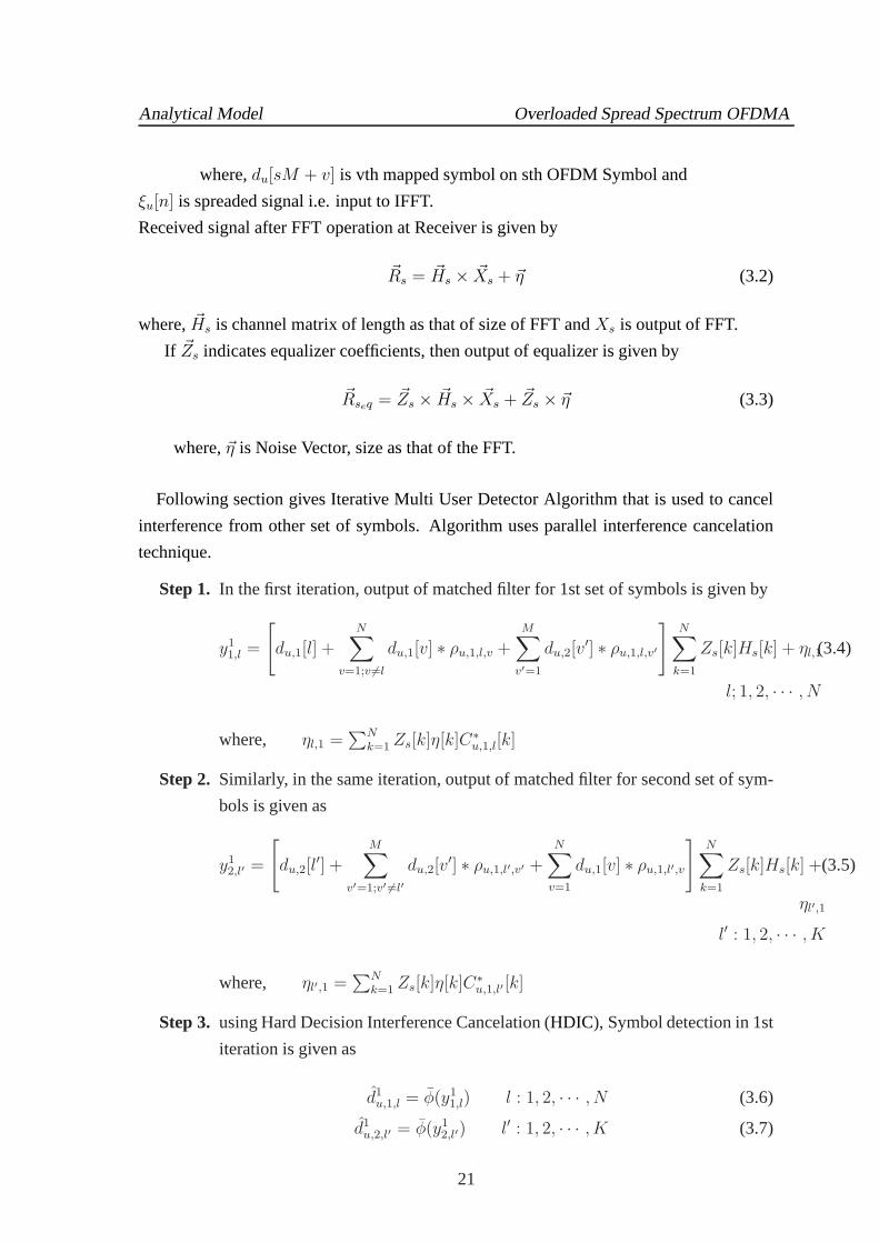
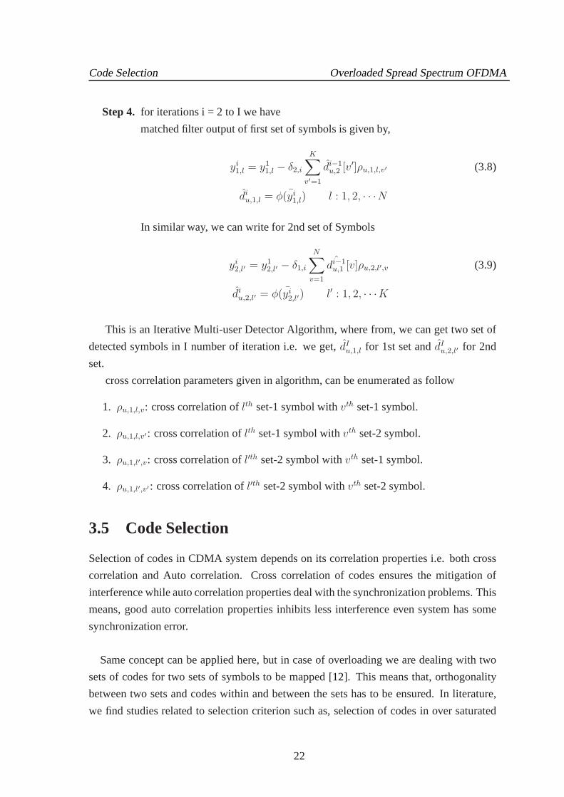


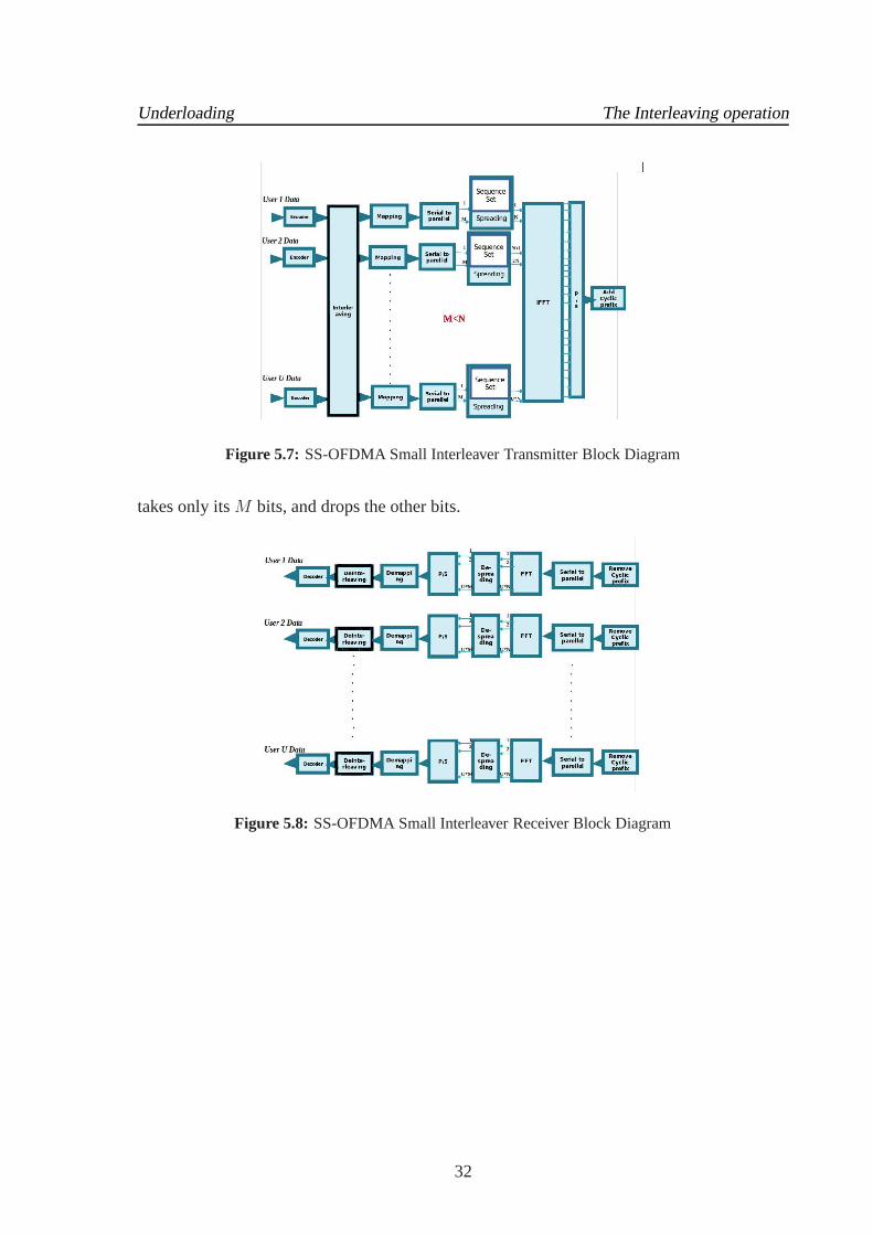

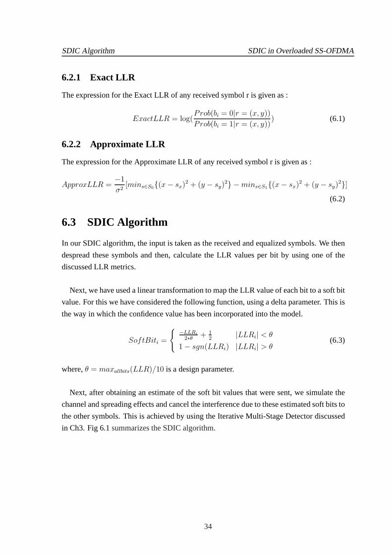


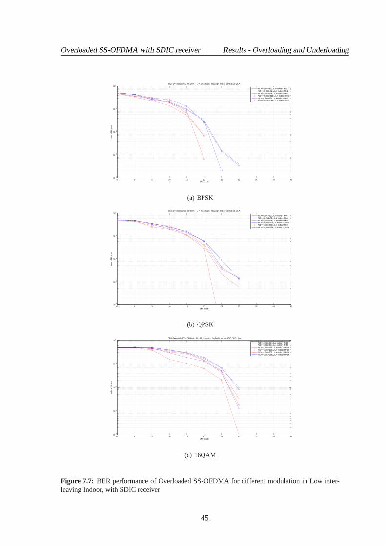


![Spectrally and Energy Efficient OFDM (SEE-OFDM) for Intensity … · 2015. 10. 29. · ACO-OFDM modulates only odd subcarriers [5] while DCO-OFDM modulates all subcarriers. Next,](https://static.documents.pub/doc/80x56/5fbf2c096a249726ce0f6214/spectrally-and-energy-eficient-ofdm-see-ofdm-for-intensity-2015-10-29-aco-ofdm.jpg)


