NASA TECHNICAL NOTE EFFECTS OF SURFACE ANDTHROUGH CRACKS ON FAILURE OF PRESSURIZED THIN-WALLED CYLINDERS OF 2014-T6 ALUMINUM by WiZZium S. Pierce . . , https://ntrs.nasa.gov/search.jsp?R=19710002575 2018-05-26T23:07:24+00:00Z
Transcript
NASA TECHNICAL NOTE
EFFECTS OF SURFACE AND THROUGH CRACKS ON FAILURE OF PRESSURIZED THIN-WALLED CYLINDERS OF 2014-T6 ALUMINUM
EFFECTS OF SURFACE AND THROUGH CRACKS ON FAILURE November 1970 O F PFtESSURIZED THIN-WALLED CYLINDEm OF 2014-T6 6. Performing Organization Code
". . . - ~ . . ~
7. Author(s) ~~~ .
8. Performing Organization Report No.
William S. Pierce E-5746 ~ ~~~ " -~ 10. Work Unit No. 9. Performing Organization Name and Address 124-08
Lewis Research Center National Aeronautics and Space Administration Cleveland, Ohio 44135
11. Contract or Grant No.
"~ ~ ~ ~~~~
13. Type of Report and Period Covered
12. Sponsoring Agency Name and Address Technical Note National Aeronautics and Space Administration Washington, D. C. 20546
14. Sponsoring Agency Code
-~ ~-~ ~
15. Supplementary Notes ~~~~~~
". ~
~~ ~ ~~ ~ ~. ".
16. Abstract
Cylinders with a 0.060-in. (0. 152-cm) wall thickness and a mean diameter of 5.6 inches (14.3 cm) were tested at -320' F (77 K). Crack lengths were varied from 0.10 to 1 .0 in. (0.25 to 2. 5 cm). Surface-crack depths ranged from 36 to 98 percent of wall thickness. In only one test was the leak-before-break phenomenon observed. For all other tests, the failure stress for the surface crack was higher than for a through-the-thickness crack of equal length. The failure stresses for cylinders containing short cracks, were less affected by crack depth than for those with long cracks. The Irwin surface-crack analysis was used to determine an apparent frac- ture toughness, which was found to be essentially constant.
17. Key Words (Suggested by Authorb)) 18. Distribution Statement
~ ___ " ~- 19. Security Classif. (of this report) I 20. Security Classif. (of this page) 22. Price' 21. NO. of Pages
Unclassified Unclassified $3.00 18 _ _ . ~ . ""
'For sale by the Clearinghouse for Federal Scientific and Technical Information Springfield, Virginia 22151
EFFECTS OF SURFACE AND THROUGH CRACKS ON FAILURE OF PRESSURIZED
THlN-WALLED CYLINDERS OF 2014-T6 ALUMINUM
by William S. Pierce
Lewis Research Center
SUMMARY
Tests were conducted to determine the effects of surface cracks on the failure stresses of pressurized cylinders. The specimens were tested at -320' F (77 K). The cylinders were 0.060 inch (0.152 cm) thick with a mean diameter of 5.6 inches (14 .3 cm). Crack lengths were varied from 0.10 to 1.0 inch (0.25 to 2 . 5 cm). Surface-crack depths ranged from 36 to 98 percent of the wall thickness.
For all tes ts but one, failure stresses for the surface cracks were higher than for a through-the-thickness crack of equal length. In only one test, was the leak-before-break phenomenon observed. In that case, the depth was 98 percent of the wall thickness.
Failure stresses for cylinders containing short cracks were much less affected by crack depth than for those with long cracks. For a crack approximately 0.12-inch (0. 30-cm) long, the failure stress decreased linearly from 90.2 to 72.0 ksi (622 to 497 MN/m ) as crack depth increased from 0 to 100 percent of the wall thickness. How- ever , a 1.0-inch (2.5-cm) long crack had a linearly decreasing failure stress from 90.2 to 23.6 ksi (622 to 163 MN/m ) for the same depth variation. 2
2
The Irwin surface-crack analysis was used to determine an apparent fracture tough- and
failure- to yield-stress ratio. ness. This value was essentially constant, independent of crack length, depth,
liting space o
INTRODUCTION
In this decade, with the advent of the space shuttle and the orb lbserva- tory, the need for more information on the effects of flaws or cracks in pressurized structures has become more important. One design approach that tends to prevent cat- astrophic failure is that of leak-before-break. In this condition a crack grows through the wall thickness and allows leakage rather than burst. Such a leakage provides a warn-
ing of possible failure. Also, repairs of the structure or component might be possible. In recent years many investigators have studied the effects of cracks on the failure
stresses of pressurized structures. Such studies have been carried out by Peters and Kuhn (ref. l), Getz, Pierce, and Calvert (ref. 2), Anderson and Sullivan (ref. 3), and others. However, all these have been studies of the effects of through-the-thickness cracks on failure stresses in relatively thin materials. Also, there have been several investigations of surface cracks in relatively thick materials. These include the re- sults of Tiffany, Lorenz, and Hall (ref. 4), Masters, Haese, and Finger (ref. 5), and others. However, little data are presently available on surface cracks in thin-walled pressure vessels.
Therefore, this program was conducted to investigate the effects of surface flaws on the failure stresses of pressurized cylinders. The material selected was the aluminum alloy 2014-T6, which is currently being used in several vehicle systems. In such sys- tems, the material may be subjected to cryogenic temperatures. Therefore, the tests were conducted at -320' F (77 K), where the material is more sensit ive to the presence of flaws or cracks. The test specimen wall thichess was nominally 0.060 inch (0.152 cm). Flaw depths were varied from one quarter to full thickness. Crack lengths ranged from 0.10 to 1.0 inch (0.25 to 2.5 cm). Failure stresses and apparent fracture tough- ness values for the various cracks were obtained and discussed. Also, strain gages were used to determine when the plastic zone extended through the wall thickness.
SYMBOLS
a
C
t
KC
KIc
%? @
U
uH
depth of surface crack (based on original fatigue shape)
half-length of through crack o r surface crack (based on original fatigue shape)
wall thickness
fracture toughness under plane-stress fracture conditions
nominal value of Kc, based on original crack length and final load
opening-mode (plane strain) fracture toughness
apparent value of KIc
complete elliptic integral of second kind for argument k2 = 1 - a /c
uniaxial tensile fracture stress (based on gross area)
hoop fracture stress for pressurized cylinder
2 2
2
OYb biaxial yield strength in 2 to 1 stress field (0.2 percent offset)
u uniaxial yield strength (0.2 percent offset) YS
BASIS OF DATA ANALYSIS
Through-the-thickness cracks in thin materials usually exhibit failure characteristics associated with plane stress. In thick sections the mode of failure is that of plane strain. When testing specimens containing surface cracks, the relation between thick or thin sections and plane-strain or plane-stress conditions is not clearly defined. The con- straint associated with surface cracks may result in the failure mode being that of mixed- mode fracture, that is, intermediate between plane stress and plane strain.
The Irwin equation (ref. 6) was used to calculate %, an apparent value of KIc. Irwin's analysis assumes that surface crack fracture is governed by plane-strain condi- tions. The actual fracture conditions for the thin material used would probably be those of the mixed mode. Although Irwin suggested that it be restricted to cases of crack depths less than half the thickness, his analysis was applied to all tests, regardless of crack depth. The equation used is
Because a biaxial stress state exists, u and u were replaced by uH and u re - spectively.
YS Yb
EXPERIMENTAL PROCEDURE
Material
The cylinders were fabricated from a single heat of unclad 2014-T6 extruded alumi- num alloy tubing. The chemical analysis of this heat is given in table I. This same heat of material was used to obtain the data reported in reference 7.
The tensile properties of this material were obtained from reference 7 and are shown in table II. A complete description of the specimens and procedures is outlined in
3
TABLE I. - CHEMICAL COMPOSITION OF 2014-T6 ALUMINUM TEST MATERIAL
aFrom ref. 8.
TABLE II. - AVERAGE TENSILE PROPERTIES O F 2014-T6 ALUMINUM TEST MATERIAL -
Specimen Test temperature
O F K
Cylinder (transverse)
20 -423 77 -320
293 70
Tensileb (longitudinal) 70 293 -320 77 -423 20 - I
aBiaxial yield strength experimentally determined to be equal to 85. 8 ks i (592 MN/III~).
this reference. Also included in tables I and II are the chemical analysis and tensile properties from reference 8.
Fracture Specimens
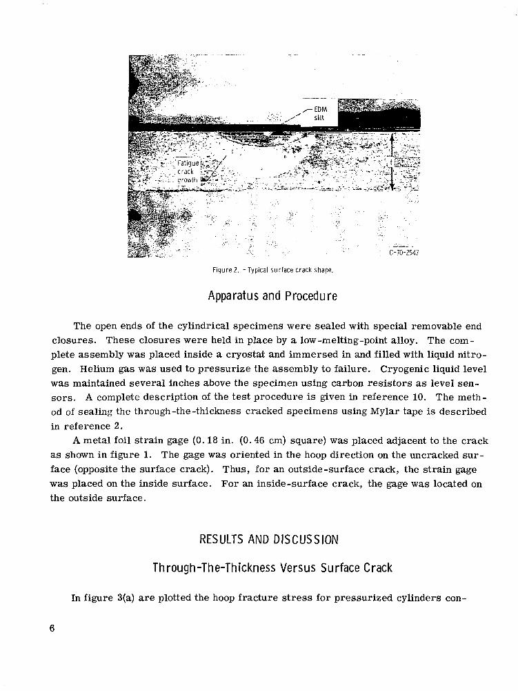
The cylindrical specimens were machined from 6-inch (15.2-cm) outside diameter by 0.25-inch (0.63-cm) wall extruded tubing. The finished wall thickness was 0.060 inch (0.152 cm) with a mean diameter of 5.63 inches (14. 3 cm). Longitudinal crack starters were made by electrical-discharge machining (EDM). The cracks were fatigue sharpened by pressure cycling using hydraulic oil. A complete description of this procedure is given in reference 9. For all specimens, the cyclic hoop stress was less than one-third the material yield strength. Figure 1 shows the specimen with cross-sectional views of the through-the-thickness crack and the surface crack. A photograph of a typical sur- face crack is shown in figure 2.
In some instances no fatigue crack growth was obtained in the length dimension. For these cases tangent lines were drawn at the ends of the fatigue region and extended to the specimen surface. The crack length was recorded to be the distance between these tan- gent and surface-line intersections as shown in figure 1.
4
5.63 in. /
17 in.
I
/
n)
/
(14.3 cm) /diam
I I
I
i
f 2r , 4
-EDM
/-Fatigue
V r' crack
I growth
Through crack
ha 8 1
. . . .
Surface cracks ' h a
CD-10864-32
Figure 1. - Typical cylindrical test specimen showing crack shape and location. Width of slit, 0.005 inch (0.013 cm). Note: 2c = 0.10 to 1.0 inch (0.25 to 2.5 cm); a = 0.024 to 0.060 inch (0.061 to 0.152 cm).
5
Figure 2. - Typical surface crack shape.
Apparatus and Procedure
." " . .
The open ends of the cylindrical specimens were sealed with special removable end closures. These closures were held in place by a low-melting-point alloy. The com- plete assembly was placed inside a cryostat and immersed in and filled with liquid nitro- gen. Helium gas was used to pressurize the assembly to failure. Cryogenic liquid level was maintained several inches above the specimen using carbon resistors as level sen- sors. A complete description of the test procedure is given in reference 10. The meth- od of sealing the through-the-thickness cracked specimens using Mylar tape is described in reference 2.
A metal foil strain gage (0.18 in. (0.46 cm) square) was placed adjacent to the crack as shown in figure 1. The gage was oriented in the hoop direction on the uncracked sur- face (opposite the surface crack). Thus, for an outside-surface crack, the strain gage was placed on the inside surface. For an inside-surface crack, the gage was located on the outside surface.
RESULTS AND DISCUSSION
Through-The-Thickness Versus Surface Crack
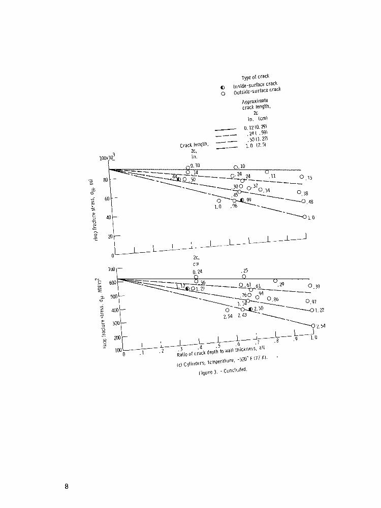
In figure 3(a) are plotted the hoop fracture stress for pressurized cylinders con-
6
Type of crack 0 Inside-surface crack 0 Outside-surface crack 0 Through-the-thickness crack
-Theoretical, eq. (21). ref. 3; Kc, = 53.1 ksi&i. (53.5 MNlm3'2 - - - Theoretical with no bulging (ref. 3) - - Through the thickness crack
(b) Tensile coupons; temperature, -423" F ( M K): data from reference 8.
~i~~~~ 3. -strength of cracked m14-~6 aluminum for var ious crack lengths and depths. Nominal thickness, 0.060 inch (0.152 cml.
7
8
taining either a surface or through-the-thickness crack with various crack lengths. For all tests but one, the failure stresses for the surface cracks, regardless of depth, were higher than those for corresponding through-the-thickness cracks of equal length. Also, there appears to be a definite layering of the surface-crack data. This layering appears to follow lines of constant a/t (ratio of crack depth to wall thickness) or constant a since t was essentially constant. Figure 3(b) shows the results obtained by Orange, Sullivan, and Calfo (ref. 8) with 2014-T6 uniaxial tensile specimens of the same thickness at -423' F (20 K). These data also tend to exhibit the layering effect but to a lesser degree. However, for a given crack length, the effect of changes in a/t is small for their ten- sile tests. This difference between uniaxial-tensile data and pressurized cylinders may be due to the pressure bulging phenomenon in the cylinders. In figure 3(a) the dashed curve represents the theoretical failure for through-the-thickness cracked cylinders if no bulging occurred. Thus, it represents the results for the 2 to 1 biaxial tensile speci- men. If one assumes that all data points below this dashed curve would fall on or above i t if no bulging were present, then the results for the tensile and cylinder data compare very well. However, different temperatures and heats of material may also have affected the results.
A s previously mentioned, one surface-cracked specimen did fail at a stress level be- low the through-the-thickness crack curve. The failure was typical of what is called leak- before-break. Shown in figure 3(a) are the points at which leakage and burst occurred. It appears, for the material and test conditions of this report, that the a/t value must be extremely high before a leak-before-break condition is possible. In this case, the depth was 98 percent of the wall thickness.
Effects of Crack Length and Depth
Figure 3(c) is a cross-plot of figure 3(a). This was done to show more clearly the interaction between crack length and depth. The failure stress was found to vary linearly with crack depth along lines of constant crack length. Therefore, lines of constant crack length were drawn from the uncracked cylinder failure stress (biaxial ultimate strength) to the through-the-thickness crack failure stress. From the data it is apparent that the failure stress for cylinders containing short cracks was only moderately affected by changes in crack depth. For example, a 0.12-inch (0. 30-cm) long crack had a linearly decreasing failure stress from 90.2 to 72.0 ksi (622 to 497 MN/m ) as crack depth in- creased from 0 to 100 percent of the wall thickness. However, a 1.0-inch (2.5-cm) long crack had a linearly decreasing failure stress from 90.2 to 23.6 ksi (622 to 163 MN/m ) for the same depth variation. Thus, it is apparent that the failure stresses for cylinders
2
2
9
containing long cracks were more affected by changes in crack depth than were those for short cracks.
Apparent Fracture Toughness
The value of apparent fracture toughness % for each surface-cracked specimen was calculated from equation (1) and reported in table III. These values are plotted in figure 4 against crack length, ratio of crack depth to wall thickness, and ratio of hoop fracture stress to biaxial yield stress. Also shown are the results obtained by Orange, Sullivan, and Calfo (ref. 8) using tensile specimens for a different heat tested at -423' F (20 K). Both the cylindrical pressure vessels and the tensile specimens gave a approximately 24.0 ksi 6 (26.4 MN/m ). The % values are independent of the previously mentioned parameters. The only trends that appeared (and these were very slight) were a decrease in KQ with increase in crack length and an increase in
3/2 % Of
TABLE III. - FRACTURE TEST DATA FOR 2014-T6 ALUMINUM CYLINDERS AT -320' F (77 K)
aLeakage occurred a t 41.0 ksi (283 MN/mz). bCornputed using s t ress a t leakage.
10
I
specimen "F (K) Type of Temperature,
0 Cylinder -320 177) A Tensile -423 (20)
"t lf I I I O I I . , I I I I I I O 0 A
10 0 .1 . 2 . 3 . 4 .5 .6 . 7 .8 . 9 1.0 1.1 1.2
Crack length, 2c. in.
I 0 . 5 1.0 1.5 2.0 2. 5
Crack length, 2c. cm N z (a) For various crack lengths.
I
301 20
I . 1
U A O@ &PA0 OA
o o 0 A
0 I . 2 . 3 . 4 . 5 . 6 . 7 . S . 9 1.0
Crack depth to wall thickness ratio, ait
(b) For various values of crack depth to wall thickness.
(c) For various ratios of hoop fracture stress to biaxial yield stress.
Figure 4. - Apparent fracture toughness of surface-cracked 2014-T6 aluminum. Nominal wall thickness, 0.060 inch (0.152 cm).
11
with an increase in hoop fracture to biaxial yield stress ratio. Thus, it might be possible to use % as a parameter for correlating uniaxial tensile data with cylindrical pressure-vessel data. However, much more information is needed before this general- ization can be made.
The values of KQ obtained using equation (1) are probably not true values for KIc. The material thickness recommendations as set forth in reference 11 for "valid" KIc tes t s were not met. Recent data in reference 12 on much thicker sections of 2014-T62 aluminum show KQ values of approximately 40 ks i & (44.0 MN/m3'2) for longi- tudinal tensile specimens.
Effects of Plast ic Zone
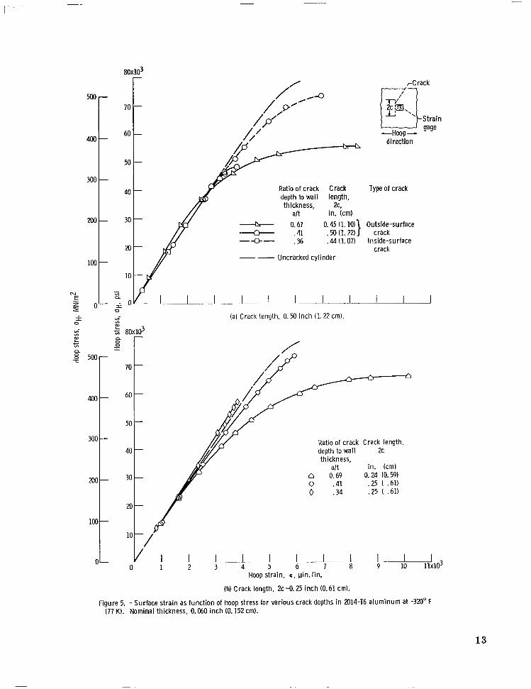
Figure 5 shows the results obtained from a strain-gage mounted on the surface op- posite the crack. The exact location is shown in the inset of figure 5(a). In each figure the dashed curve represents the hoop strain measured on an uncracked cylinder. Fig- u re s 5(a) and (b), for crack lengths of 0. 50 and 0.25 inch (1.22 and 0.61 cm), respec- tively, show large deviations from the strain in an uncracked cylinder for high values of a/t. This deviation is the result of the plastic zone extending through the thickness of the material.
The actual size of the plastic zone has been studied by many investigators. A sum- mary of these studies along with some experimental results is given in reference 13. Based on the conclusions of this reference, the start of this deviation at about 40 ksi (276 MN/m ) appears reasonable. 2
In figure 5(c), for a crack length of only 0.10 inch (0.25 cm), no appreciable de- viation from the results for an uncracked cylinder was observed, regardless of the a/t value. This may be the result of the insensitivity of the relatively large strain gage (0.18 in. (0.46 cm) square) to a highly localized strain around a very short crack. Also, on this short crack, the location of the gage was quite critical and could have been mis- alined since the crack and gage were on opposite surfaces.
Figure 5(d) is a plot of the hoop s t ra in for cracks having nearly equal a/t values in contrast to constant 2c of figures 5(a) to (c). From these data, it appears that the plastic-zone size is a function of crack length as well as crack depth.
Ins ide Versus Outs ide Sur face Cracks
In order to determine possible differences between failure stresses associated with inside- and outside-surface cracks, two test specimens were tested which contained
12
80x103
5 T
a
-
- Ratio of crack Crack depth to wall length, thickness, 2c.
al t in. (cm) - 0.67 - .41 O. .50 45 (l. (1.22) lo)) -Q- .36 .44 (1.07)
" Uncracked cylinder
(a) Crack length, 0.50 inch (1.22 cm).
rCrack
Strain gage
--HOOP& direction
Type of crack
Outside-surface
Inside-surface crack
crack
Ratio of crack Crack length. depth to wall 2C thickness,
al t n 0.69 0.24 (0.59)
in. (cm)
0 .41 .25 ( .61) 0 .34 .25 ( .61)
Hoop strain, 6 . pin.lin.
(b) Crack length, 2 ~ 4 . 2 5 i n c h (0.61 cm).
"
Figure 5. - Surface strain as function of hoop stress for various crack depths in 2014-T6 a luminum at -320" F (77 KI. Nominal thickness, 0.060 i n c h (0.152 cm).
13
600 -
500-
m-
300 -
200-
L c L v)
CL 0 0 I
500 -
400-
300 -
200 -
loo -
0-
Ratio of crack Crack depth to wall length, thickness, 2c.
Ratio of crack Crack deoth to wall lenqth. - . thickness,
alt 2c I
i n . (crn)
0 0.67 0.45 (1. 14) . 6 9 .24 (.61)
D .66 . 10 (. 25)
I I- ~
0 1 2 3 4 5 6 7 8 9 IO 11x103 Hoop strain, c, pin. l in .
(dl Crack depth to wall thickness ratio, 0.67.
Figure 5. - Concluded.
14
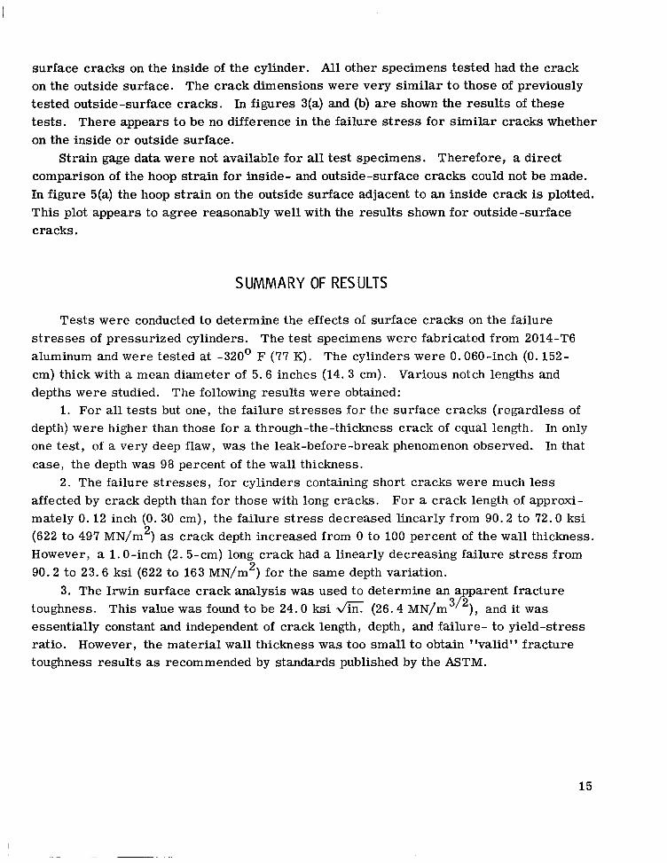
surface cracks on the inside of the cylinder. All other specimens tested had the crack on the outside surface. The crack dimensions were very similar to those of previously tested outside-surface cracks. In figures 3(a) and (b) are shown the results of these tests. There appears to be no difference in the failure stress for similar cracks whether on the inside or outside surface.
Strain gage data were not available for all test specimens. Therefore, a direct comparison of the hoop strain for inside- and outside-surface cracks could not be made. In figure 5(a) the hoop s t ra in on the outside surface adjacent to an inside crack is plotted. This plot appears to agree reasonably well with the results shown for outside-surface cracks.
SUMMARY OF RESULTS
Tests were conducted to determine the effects of surface cracks on the failure s t r e s ses of pressurized cylinders. The test specimens were fabricated from 2014-T6 aluminum and were tested at -320' F (77 K). The cylinders were 0.060-inch (0.152- cm) thick with a mean diameter of 5.6 inches (14. 3 cm). Various notch lengths and depths were studied. The following results were obtained:
1. For all tes ts but one, the failure stresses for the surface cracks (regardless of depth) were higher than those for a through-the-thickness crack of equal length. In only one tes t , of a very deep flaw, was the leak-before-break phenomenon observed. In that case, the depth was 98 percent of the wall thickness.
2. The failure stresses, for cylinders containing short cracks were much less affected by crack depth than for those with long cracks. For a crack length of approxi- mately 0.12 inch (0. 30 cm), the failure stress decreased linearly from 90.2 to 72.0 ksi (622 to 497 MN/m ) as crack depth increased from 0 to 100 percent of the wall thickness. However, a 1.0-inch (2. 5-cm) long crack had a linearly decreasing failure stress from 90.2 to 23.6 ksi (622 to 163 MN/m2) for the same depth variation.
3. The Irwin surface crack analysis was used to determine an apparent fracture toughness. This value was found to be 24.0 ksi & (26.4 MN/m 3/2) , and it was essentially constant and independent of crack length, depth, and failure- to yield-stress ratio. However, the material wall thickness was too small to obtain "valid" fracture toughness results as recommended by standards published by the ASTM.
2
15
4. Two specimens were tested that contained inside-surface cracks. There appears t o be no difference in the failure stresses for s imilar cracks whether on the inside or outside surface.
Lewis Research Center, National Aeronautics and Space Administration,
Cleveland, Ohio, August 6, 1970, 124-08.
REFERENCES
1. Peters, Roger W. ; and Kuhn, Paul: Bursting Strength of Unstiffened Pressure Cyl- inders with Slits. NACA TN 3993, 1957.
2. Getz, David F. ; Pierce, William S. ; and Calvert, Howard F. : Correlation of Uni- axial Notch Tensile Data with Pressure-Vessel Fracture Characteristics. Paper 63-WA-187, ASME, 1963.
3. Anderson, Robert B. ; and Sullivan, Timothy L. : Fracture Mechanics of Through- Cracked Cylindrical Pressure Vessels. NASA TN D-3252, 1966.
4. Tiffany, C. F. ; Lorenz, P. M. ; and Hall, L. R. : Investigation of Plane-Strain Flaw Growth in Thick-Walled Tanks. Rep. D2-24078-1, Boeing Co. (NASA CR-54837), Feb. 1966.
5. Masters, J. N. ; Haese, W. P. ; and Finger, R. W. : Investigation of Deep Flaws in Thin Walled Tanks. Boeing Co. (NASA CR-72606), Dec. 1969.
6. Irwin, G. R. : Crack-Extension Force for a Part-Through Crack in a Plate. J. Appl. Mech., vol. 29, no. 4, Dec. 1962, pp. 651-654.
7. Pierce, William S. : Crack Growth in 2014-T6 Aluminum Tensile and Tank Specimens Cyclically Loaded at Cryogenic Temperatures. NASA TN D-4541, 1968.
8. Orange, Thomas W. ; Sullivan, Timothy L. ; and Calfo, Frederick C. : Fracture of Thin Sections Containing Through and Part-Through Cracks. Presented at the ASTM Symposium on Fracture Toughness Testing at Cryogenic Temperatures, Toronto, Canada, June 22-26, 1970.
9. Calfo, Frederick D. : Effect of Residual Stress on Fracture Strength of AIS1 301 Stainless-Steel and Ti-5A1-2.5Sn ELI Titanium Cracked Thin-Wall Cylinders. NASA TN D-4777, 1968.
16
NASA-Langley, 1970 - 32 E-5746 17
NATIONAL AERONAUTICS AND SPACE ADMINISTRATION WASHINGTON, D. C. 20546
OFFICIAL BUSINESS FIRST CLASS MAIL
NATIONAL AERONAUTICS A h POSTAGE AND FEES PAID
SPACE ADMINISTRATION
POSTMASTER: If Undeliverable (Section 155 Post31 Manual) Do Not Retur
NASA SCIENTIFIC AND TECHNICAL PUBLICATIONS
TECHNICAL REPORTS: Scientific and technical information considered important, complete, and a lasting contribution to esisting knowledge.
TECHNICAL NOTES: Information less broad in scope but nevertheless of importance as a contribution to existing .knowledge.
TECHNICAL MEMORANDUMS: Information receiving limited distribution because of preliminary data, security classifica- tion, or other reasons.
TECHNICAL TRANSLATIONS: Information publ.ished in a foreign language considered to merit NASA distribution in English. .
/
SPECIAL PUBLICATIONS: Information derived from or of value to NASA activizies. Publications include conference proceedings, monographs, data compilations, handbooks, sourcebooks, and special bibliographies.
TECHNOLOGY UTILIZATION PUBLICATIONS: Information on technology used by NASA that may be of particular
CONTRACTOR REPORTS: Scientific and technical information generated under a NASA TEchnology Reports and N ~ ~ ~ ~ , contract or grant and considered an important contribution to existing knowledge.
interest in commercial and other non-aerospace npplications. Publications include Tech Briefs,
and Technology Surveys.
Details on the availability of these publications may be obtained from:
SCIENTIFIC AND TECHNICAL INFORMATION DIVISION
NATIONAL AERONAUTICS AND SPACE ADMINISTRATION Washington, D.C. 20546