A strongly increased number of solar heating plants have been built and are under construction in Denmark [1]. The solar collectors used in the solar heating plants are flat plate solar collectors and often the volume flow rate through the collector field is varying. If the solar irradiance is high the volume flow rate is high, if the solar irradiance is low the volume flow rate is low. When the efficiency of a solar collector is determined often only one volume flow rate is used. Actually the efficiency of a solar collector is influenced by the volume flow rate. Only if the influence of the volume flow rate on the collector efficiency is known, it will be possible to determine the optimal operation strategy for a solar collector field. Therefore two flat plate solar collectors used for solar heating plants from Arcon Solvarme A/S are tested side by side in a laboratory solar collector test facility at Technical University of Denmark (DTU) with different flow rates, see Fig.1. Evaluation of the test method for solar collector efficiency and
66 Ziqian Chen et al. / Energy Procedia 30 ( 2012 ) 65 – 72
the effect of the volume flow rate on the efficiency of a solar collector were discussed in [2] and [3]. Also the flow distributions in flat plate solar collectors under different conditions were studied in [4] and [5]. Furthermore the performance and efficiency of flat plate solar collector arrays have been analyzed in [6]. In this paper, the tests on the efficiencies of two flat plate solar collectors at different flow rates have been carried out. The measured efficiencies are compared with the efficiencies calculated with the program SOLEFF which is a simulation program for flat plate solar collectors [7]. Based on the investigations efficiency expressions are determined for the collectors with different volume flow rates.
Nomenclature F volume flow rate (l/s) G total irradiance (W/m2) H calculated efficiency of solar collectors (-) IAM incidence angle modifier (-) N number of values (-) RMSD root mean square deviation, defined in Eq.(2) T temperature (°C) T0 specific temperature (°C) T*
m reduced temperature difference = (Tm-Ta)/G, (K m2/W ) X variable (-) η measured efficiency of solar collector (-) Subscript 1 flow rate at 25 l/min 2 flow rate at 10 l/min 3 flow rate at 5 l/min a ambient c calculated m mean value n collector without ETFE foil t measured w collector with ETFE foil
2. Experiments
2.1. Experimental setup
The efficiency expressions and incidence angle modifiers for two flat plate solar collectors for solar heating plants are measured side-by-side with different volume flow rates at DTU according to [8], see Fig.1. The collectors are from Arcon Solvarme A/S. The collectors are identical with the exception that one collector is equipped with an ETFE foil between the absorber and the cover glass, while the other collector is without an ETFE foil. The test conditions for the collectors are listed in table 1. The aperture areas for the collector with ETFE foil and the collector without ETFE foil are 12.55 m2 and 12.57 m2. The geometric dimensions for both collectors are 5.96 m 2.27 m 0.14 m. The absorbers are made with copper and aluminium with 18 parallel horizontal strips and with 2 vertical manifolds. The coating for the
Ziqian Chen et al. / Energy Procedia 30 ( 2012 ) 65 – 72 67
absorbers is a selective Tinox coating and the outer covers for the collectors are anti-reflective glass covers. The insulations for the collectors are mineral wool.
Fig. 1. Photo of two flat plate solar collectors for tests
Table 1. Test conditions for two flat plate solar collectors
Test No. Solar collector fluid Volume flow rate (l/min) Collector tilt,°
1 40% propylene glycol/water mixture 25 45
2 40% propylene glycol/water mixture 10 45
3 40% propylene glycol/water mixture 5 45
2.2. Experimental results
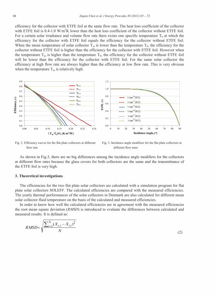
Based on the measurements the efficiency expressions and the incidence angle modifiers were found for the collectors. The efficiency curves for a solar irradiance of 1000 W/m2 and the incidence angle modifier for the two solar collectors at different flow rates are shown in Fig.2 and Fig.3. The efficiency expressions are:
From Fig.2 and from equation (1-1) to equation (1-6), it is found that the start efficiencies both for the collector with ETFE foil and for the collector without ETFE foil increase with the increase of the flow rate. And the start efficiency for the collector without ETFE foil is 2-3 %-points higher than the start
Collector with ETFE foil Collector without ETFE foil
68 Ziqian Chen et al. / Energy Procedia 30 ( 2012 ) 65 – 72
efficiency for the collector with ETFE foil at the same flow rate. The heat loss coefficient of the collector with ETFE foil is 0.4-1.0 W/m2K lower than the heat loss coefficient of the collector without ETFE foil. For a certain solar irradiance and volume flow rate there exists one specific temperature T0 at which the efficiency for the collector with ETFE foil equals the efficiency for the collector without ETFE foil. When the mean temperature of solar collector Tm is lower than the temperature T0, the efficiency for the collector without ETFE foil is higher than the efficiency for the collector with ETFE foil. However when the temperature Tm is higher than the temperature T0, the efficiency for the collector without ETFE foil will be lower than the efficiency for the collector with ETFE foil. For the same solar collector the efficiency at high flow rate are always higher than the efficiency at low flow rate. This is very obvious when the temperature Tm is relatively high.
Fig. 2. Efficiency curves for the flat plate collectors at different
flow rate Fig. 3. Incidence angle modifiers for the flat plate collectors at
different flow rates
As shown in Fig.3, there are no big differences among the incidence angle modifiers for the collectors at different flow rates because the glass covers for both collectors are the same and the transmittance of the ETFE foil is very high.
3. Theoretical investigations
The efficiencies for the two flat plate solar collectors are calculated with a simulation program for flat plate solar collectors SOLEFF. The calculated efficiencies are compared with the measured efficiencies. The yearly thermal performances of the solar collectors in Denmark are also calculated for different mean solar collector fluid temperature on the basis of the calculated and measured efficiencies.
In order to know how well the calculated efficiencies are in agreement with the measured efficiencies the root mean square deviation (RMSD) is introduced to evaluate the differences between calculated and measured results. It is defined as:
NXX
RMSDNi itic1
2,, )(
(2)
0.0
0.1
0.2
0.3
0.4
0.5
0.6
0.7
0.8
0.9
0.00 0.05 0.10 0.15 0.20 0.25 0.30
Eff
icie
ncy,
(-)
Tm-Ta)/G, (K m2/W)
η1,w
η1,n
η2,w
η3,w
η2,n
η3,n
0.0
0.2
0.4
0.6
0.8
1.0
1.2
0 10 20 30 40 50 60 70 80 90
IAM
, (-)
Incidence Angle, (o)
1-tan3.8(θ/2)
1-tan3.8(θ/2)
1-tan3.7(θ/2)
1-tan3.7(θ/2)
1-tan3.6(θ/2)
1-tan3.8(θ/2)
Ziqian Chen et al. / Energy Procedia 30 ( 2012 ) 65 – 72 69
3.1. Theoretical efficiencies of flat plate solar collectors
Based on the measured data of total solar irradiance, diffuse solar irradiance, volume flow rate of collector fluid, ambient temperature, mean temperature of collector fluid, wind speed as well as the geometric and physical parameters of the flat plate solar collectors, the efficiencies are calculated with SOLEFF. The measured and calculated efficiency points for the collector without ETFE foil and for the collector with ETFE foil under the same conditions are shown in Fig.4 and Fig.5. The RMSD for efficiencies for the collector without ETFE and the collector with ETFE at different flow rates are 0.006 and 0.005. That is: There is a good agreement between measured and calculated efficiencies.
Fig. 4. Measured and calculated efficiencies for the flat
plate collector without foil at different flow rates Fig. 5. Measured and calculated efficiencies for the flat
plate collector with foil at different flow rates
Fig. 6. Efficiency curves from measured and calculated
results for the flat plate collector without foil at different flow rates
Fig. 7. Efficiency curves from measured and calculated results for the flat plate collector with foil at different flow rates
0.5
0.6
0.7
0.8
0.9
0.00 0.02 0.04 0.06 0.08 0.10
Eff
icie
ncy
with
out f
oil,
(-)
Tm-Ta)/G, (K m2/W)
Measured, 25 l/min
Calculated, 25 l/min
Measuredl, 10 l/min
Calculatedl, 10 l/min
Measured, 5 l/min
Calculated,5 l/min
0.5
0.6
0.7
0.8
0.9
0.00 0.02 0.04 0.06 0.08 0.10
Eff
icie
ncy
with
foil,
(-)
Tm-Ta)/G, (K m2/W)
Measured, 25 l/min
Calculated, 25 l/min
Measuredl, 10 l/min
Calculatedl, 10 l/min
Measured, 5 l/min
Calculated,5 l/min
0.3
0.4
0.5
0.6
0.7
0.8
0.9
0.00 0.02 0.04 0.06 0.08 0.10
Eff
icie
ncy
, (-)
Tm-Ta)/G, (K m2/W)
H1,n
H2,n
H3,n
η1,n
η2,n
η3,n
0.3
0.4
0.5
0.6
0.7
0.8
0.9
0.00 0.02 0.04 0.06 0.08 0.10
Eff
icie
ncy,
(-)
Tm-Ta)/G, (K m2/W)
H1,w
H2,w
H3,w
η1,w
η2,w
η3,w
70 Ziqian Chen et al. / Energy Procedia 30 ( 2012 ) 65 – 72
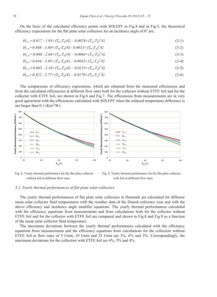
On the basis of the calculated efficiency points with SOLEFF in Fig.4 and in Fig.5, the theoretical efficiency expressions for the flat plate solar collectors for an incidence angle of 0° are:
The comparisons of efficiency expressions, which are obtained from the measured efficiencies and
from the calculated efficiencies at different flow rates both for the collector without ETFE foil and for the collector with ETFE foil, are shown in Fig.6 and Fig.7. The efficiencies from measurements are in very good agreement with the efficiencies calculated with SOLEFF when the reduced temperature difference is not larger than 0.1 (Km2/W).
Fig. 8. Yearly thermal performance for the flat plate collector
without foil at different flow rates Fig. 9. Yearly thermal performance for the flat plate collector
with foil at different flow rates
3.2. Yearly thermal performances of flat plate solar collectors
The yearly thermal performances of flat plate solar collectors in Denmark are calculated for different mean solar collector fluid temperatures with the weather data of the Danish reference year and with the above efficiency and incidence angle modifier equations. The yearly thermal performances calculated with the efficiency equations from measurements and from calculations both for the collector without ETFE foil and for the collector with ETFE foil are compared and shown in Fig.8 and Fig.9 as a function of the mean solar collector fluid temperature.
The maximum deviations between the yearly thermal performances calculated with the efficiency equations from measurements and the efficiency equations from calculations for the collectors without ETFE foil at flow rates of 5 l/min, 10 l/min and 25 l/min are 3%, 6% and 3%. Correspondingly, the maximum deviations for the collectors with ETFE foil are 4%, 5% and 4%.
0
100
200
300
400
500
600
700
800
20 40 60 80 100
Year
ly th
erm
al p
erfo
rman
ce, (
kWh/
m2)
Tm, (°)
η1,n
η2,n
η3,n
H1,n
H2,n
H3,n
0
100
200
300
400
500
600
700
800
20 40 60 80 100
Year
ly th
erm
al p
erfo
rman
ce, (
kWh/
m2)
Tm, (°)
η1,w
η2,w
η3,w
H1,w
H2,w
H3,w
Ziqian Chen et al. / Energy Procedia 30 ( 2012 ) 65 – 72 71
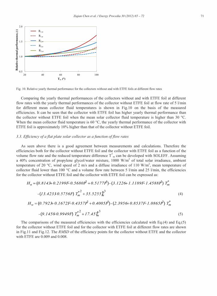
Fig. 10. Relative yearly thermal performance for the collectors without and with ETFE foils at different flow rates
Comparing the yearly thermal performances of the collectors without and with ETFE foil at different flow rates with the yearly thermal performances of the collector without ETFE foil at flow rate of 5 l/min for different mean collector fluid temperatures is shown in Fig.10 on the basis of the measured efficiencies. It can be seen that the collector with ETFE foil has higher yearly thermal performance than the collector without ETFE foil when the mean solar collector fluid temperature is higher than 30 °C. When the mean collector fluid temperature is 60 °C, the yearly thermal performance of the collector with ETFE foil is approximately 10% higher than that of the collector without ETFE foil.
3.3. Efficiency of a flat plate solar collector as a function of flow rates
As seen above there is a good agreement between measurements and calculations. Therefore the efficiencies both for the collector without ETFE foil and the collector with ETFE foil as a function of the volume flow rate and the reduced temperature difference T*
m can be developed with SOLEFF. Assuming a 40% concentration of propylene glycol/water mixture, 1000 W/m2 of total solar irradiance, ambient temperature of 20 °C, wind speed of 2 m/s and a diffuse irradiance of 110 W/m2, mean temperature of collector fluid lower than 100 °C and a volume flow rate between 5 l/min and 25 l/min, the efficiencies for the collector without ETFE foil and the collector with ETFE foil can be expressed as:
The comparisons of the measured efficiencies with the efficiencies calculated with Eq.(4) and Eq.(5) for the collector without ETFE foil and for the collector with ETFE foil at different flow rates are shown in Fig.11 and Fig.12. The RMSD of the efficiency points for the collector without ETFE and the collector with ETFE are 0.009 and 0.008.
0.5
1.0
1.5
2.0
20 40 60 80 100
Rel
ativ
e the
rmal
per
form
ance
, (-)
Tm, (°)
R1,w
R2,w
R3,w
R1,n
R2,n
72 Ziqian Chen et al. / Energy Procedia 30 ( 2012 ) 65 – 72
Fig. 11. Measured efficiencies and calculated efficiencies with
Eq.(4) for the flat plate collector without foil at different flow rates
Fig.12. Measured efficiencies and calculated efficiencies with Eq.(5) for the flat plate collector with foil at different flow rates
4. Conclusions
The start efficiency for the collector without ETFE foil is 2-3% points higher than the start efficiency of the collector with ETFE foil. The heat loss coefficient of the collector with ETFE foil is about 0.4-1.0 W/m2K lower than the heat loss coefficient of the collector without ETFE foil. The incidence angle modifier is almost identical for the collectors without and with ETFE foil.
If the volume flow rate of solar collector fluid is increasing, the efficiency, the start efficiency and the incidence angle modifier are increasing and the heat loss coefficient is decreasing.
The yearly thermal performance for the collector with ETFE foil is higher than the yearly thermal performance for the collector without ETFE foil when the mean solar collector fluid temperature is higher than 30 ºC. When the mean collector fluid temperature is 60 ºC, the yearly thermal performance of the collector with ETFE foil is approximately 10% higher than that of the collector without ETFE foil.
References
[1] http://www.solar-district-heating.eu/SDH/LargeScaleSolarHeatingPlants.aspx [2] Fan J, Shah LJ, Furbo S. Evaluation of Test Method for Solar Collector Efficiency, Proceedings of Eurosun 2006, Glasgow,
UK, ISES-Europe [3] Fan J, Shah LJ, Furbo S. The Effect of the Volume Flow rate on the Efficiency of a Solar Collector, Proceedings of Eurosun
2006, Glasgow, UK, ISES-Europe [4] Jones GF, Lior NL. Flow distribution in manifolded solar collectors with negligible buoyancy effects. Solar Energy 1994;
52(3): 289-300 [5] Weitbrecht V, Lehmann D, Richter A. Flow distribution in solar collectors with laminar flow conditions. Solar Energy 2002;
73(6): 433-441 [6] Wang XA, Wu LG. Analysis and performance of flat-plate solar collector arrays. Solar Energy 1990; 45(2): 71-78 [7]Rasmussen PB, Svendsen S. “SolEff Program til beregning af solfangeres effektivitet”. Brugervejledning og generel
programdokumentation, Thermal Insulation Laboratory, Technical University of Denmark; 1996. [8]European Committee for Standardization. “Thermal solar systems and components – Solar collectors – Part 2: Test methods”,