238
EFFICIENCY STANDARDS CALIFORNIA CODE OF REGULATIONS TITLE 24, PART 6

EFFICIENCY STANDARDS CALIFORNIA CODE OF REGULATIONS
TITLE 24, PART 6

2013 2016 Building Energy Efficiency Standards Page 1
SECTION 100.0 – SCOPE
SUBCHAPTER 1 ALL OCCUPANCIES—GENERAL PROVISIONS
SECTION 100.0 – SCOPE (a) Buildings Covered. The provisions of Part 6 apply to all buildings:
1. That are of Occupancy Group A, B, E, F, H, M, R, S, or U; and
2. For which an application for a building permit or renewal of an existing permit is filed (or is required by law to be filed) on or after the effective date of the provisions, or which are constructed by a governmental agency; and
3. That are:
A. Unconditioned; or
B. Indirectly or directly conditioned, by mechanical heating or mechanical cooling, or process spaces; or
C. Low-rise residential buildings that are heated with a non-mechanical heating system.
EXCEPTION 1 to Section 100.0(a): Qualified historic buildings, as regulated by the California Historic Building Code (Title 24, Part 8). Lighting in qualified historic buildings shall comply with the applicable requirements in Section 140.6(a)3Q.
EXCEPTION 2 to Section 100.0(a): Building departments, at their discretion, may exempt temporary buildings, temporary outdoor lighting or temporary lighting in an unconditioned building, or structures erected in response to a natural disaster. Temporary buildings or structures shall be completely removed upon the expiration of the time limit stated in the permit.
(b) Parts of Buildings Regulated. The provisions of Part 6 apply to the building envelope, space-conditioning systems, water-heating systems, pool and spas, solar ready buildings, indoor lighting systems of buildings, outdoor lighting systems, and signs located either indoors or outdoors, in buildings that are
1. Covered by Section 100.0(a), and
2. Set forth in TABLE 100.0-A.
(c) Habitable Stories.
1. All conditioned space in a story shall comply with Part 6 whether or not the story is a habitable space.
2. All unconditioned space in a story shall comply with the lighting requirements of Part 6 whether or not the story is a habitable space.
(d) Outdoor Lighting and Indoor and Outdoor Signs. The provisions of Part 6 apply to outdoor lighting systems and to signs located either indoors or outdoors as set forth in TABLE 100.0-A.
(e) Sections Applicable to Particular Buildings. TABLE 100.0-A and this subsection list the provisions of Part 6 that are applicable to different types of buildings covered by Section 100.0(a).
1. All buildings. Sections 100.0 through 110.10 apply to all buildings.
EXCEPTION to Section 100.0(e)1: Spaces or requirements not listed in TABLE 100.0-A.
2. Newly constructed buildings.
A. All newly constructed buildings. Sections 110.0 through 110.10 apply to all newly constructed buildings within the scope of Section 100.0(a). In addition, newly constructed buildings shall meet the requirements of Subsections B, C, D or E, as applicable.
B. Nonresidential, high-rise residential, and hotel/motel buildings that are mechanically heated or mechanically cooled.

Page 2 2013 2016 Building Energy Efficiency Standards
SECTION 100.0 – SCOPE
i. Sections applicable. Sections 120.0 through 140.8 apply to newly constructed nonresidential buildings, high-rise residential buildings, and hotels/motels that are mechanically heated or mechanically cooled.
ii. Compliance approaches. In order to comply with Part 6 newly constructed nonresidential buildings, high-rise residential buildings, and hotels/motels that are mechanically heated or mechanically cooled must meet the requirements of:
a. Mandatory measures: The applicable provisions of Sections 120.0 through 130.5; and
b. Either:
(i) Performance approach: Section 140.1; or
(ii) Prescriptive approach: Sections 140.2 through 140.8.
C. Unconditioned nonresidential buildings and process space. Sections 110.10, 120.6, 130.0 through 130.5, 140.3(c), 140.6, 140.7, and 140.8 apply to all newly constructed unconditioned buildings and 140.3(c), 140.1, and 141.0 for process spaces within the scope of Section 100.0(a).
D. Low-rise residential buildings.
i. Sections applicable. Sections 150.0 through 150.1 apply to newly constructed low-rise residential buildings.
ii. Compliance approaches. In order to comply with Part 6 newly constructed low-rise residential buildings must meet the requirements of:
a. Mandatory measures: The applicable provisions of Sections 110.0 through 110.10, and 150.0; and
b. Either:
(i) Performance approach: Section 150.1(a) and (b); or
(ii) Prescriptive approach: Section 150.1(a) and (c).
EXCEPTION 1 to Section 100.0(e)2Diib: Seasonally occupied agricultural housing limited by state or federal agency contract to occupancy not more than 180 days in any calendar year.
EXCEPTION 2 to Section 100.0(e)2Diib: Low-rise residential buildings that are heated with a wood heater or another nonmechanical heating system and that use no energy obtained from depletable sources for lighting or water heating.
E. Covered Processes.
i. Sections applicable. Sections 110.2, 120.6 and 140.9 apply to covered processes.
ii. Compliance approaches. In order to comply with Part 6 covered processes must meet the requirements of:
a. The applicable mandatory measures in Section 120.6; and
b. Either:
(i) The Performance approach requirements of Section 140.1; or
(ii) The Prescriptive approach requirements of Section 140.9.
Note: If covered processes do not have prescriptive requirements, then only the applicable mandatory measures in Section 120.6 must be met.
3. New construction in existing buildings.
A. Nonresidential, high-rise residential, and hotel/motel buildings. Section 141.0 applies to new construction in existing buildings that will be nonresidential, high-rise residential, and hotel/motel occupancies.
B. Low-rise residential buildings. Section 150.2 applies to new construction in existing buildings that will be low-rise residential occupancies.

2013 2016 Building Energy Efficiency Standards Page 3
SECTION 100.0 – SCOPE
4. Installation of insulation in existing buildings. Section 110.8(d) applies to buildings in which insulation is being installed in existing attics, or on existing water heaters, or existing space conditioning ducts.
5. Outdoor Lighting. Sections 110.9, 130.0, 130.2, 130.4, 140.7, and 150.0 apply to newly constructed outdoor lighting systems, and Section 141.0 applies to outdoor lighting that is either added or altered.
6. Signs. Sections 130.0, 130.3 and 140.8 apply to newly constructed signs located either indoors or outdoors and Section 141.0 applies to sign alterations located either indoors or outdoors.
(f) Mixed Occupancy. When a building is designed and constructed for more than one type of occupancy (residential and nonresidential), the space for each occupancy shall meet the provisions of Part 6 applicable to that occupancy.
EXCEPTION 1 to Section 100.0(f): If one occupancy constitutes at least 80 percent of the conditioned floor area of the building, the entire building envelope, HVAC, and water heating may be designed to comply with the provisions of Part 6 applicable to that occupancy, provided that the applicable lighting requirements in Sections 140.6 through 140.8 or 150.0(k) are met for each occupancy and space and mandatory measures in Sections 110.0 through 130.5, and 150.0 are met for each occupancy and space.
EXCEPTION 2 to Section 100.0(f): If one occupancy constitutes at least 90 percent of the combined conditioned plus unconditioned floor area of the building, the entire building indoor lighting may be designed to comply with only the lighting provisions of Part 6 applicable to that occupancy.
(g) Administrative Requirements. Administrative requirements relating to permit requirements, enforcement by the Commission, locally adopted energy standards, interpretations, claims of exemption, approved calculation methods, rights of appeal, and certification and labeling requirements of fenestration products and roofing products are specified in California Code of Regulations, Title 24, Part 1, Sections 10-101 to 10-114.
(h) Certification Requirements for Manufactured Equipment, Products, and Devices. Part 6 limits the installation of the following manufactured equipment, products, and devices to:
1. For items listed below that are regulated by Title 20, limited to those that have been certified to the Energy Commission by their manufacturer, pursuant to the provisions of Title 20 California Code of Regulations, Section 1606, to meet or exceed minimum specifications or efficiencies adopted by the Commission; or
2. For items listed below that are required to be certified to the Energy Commission and are not regulated by Title 20, limited to those certified by the manufacturer in a declaration, executed under penalty of perjury under the laws of the State of California, that all the information provided pursuant to the certification is true, complete, accurate and in compliance with all applicable provisions of Part 6; and if applicable that the equipment, product, or device was tested under the applicable test method specified in Part 6; or
3. For items listed below that are required to be listed in directories or certified by someone other than the Energy Commission, limited to those that comply with the applicable provisions of Item 4, below.
A. Central air-conditioning heat pumps and other central air conditioners (Sections 110.1 and 110.2).
B. Combination equipment: space heating and cooling, or space heating and water heating (Section 110.2(a)3).
C. Fenestration products (Section 110.6).
D. Fluorescent lamp ballasts (Section 110.1).
E. Gas space heaters (Sections 110.1 and 110.2).
F. Insulating materials and roofing products (Section 110.8).
G. Lighting control devices and lighting control systems (Section 110.9).
H. Oil-fired storage water heaters (Section 110.3).
I. Other heating and cooling equipment (Sections 110.1 and 110.2).
J. Plumbing fittings (Section 110.1).
K. Pool heaters (Section 110.4).
L. Refrigerators, refrigerator-freezers, and freezers (Section 110.1).

Page 4 2013 2016 Building Energy Efficiency Standards
SECTION 100.0 – SCOPE
M. Room air conditioners (Section 110.1).
N. Slab floor perimeter insulation (Section 150.0 (l)).
O. Water heaters (Section 110.3).
P. Track lighting integral current limiter (Section 110.9).
Q. High efficacy LED light sources (Section 110.9).
R. Ballasts for residential recessed luminaires (Section 110.9).
4. The certification status of any such manufactured device shall be confirmed only by reference to:
A. A directory published or approved by the Commission; or
B. A copy of the application for certification from the manufacturer and the letter of acceptance from the Commission staff; or
C. Written confirmation from the publisher of a Commission-approved directory that a device has been certified; or
D. A Commission-approved label on the device.
5. Part 6 does not require a builder, designer, owner, operator, or enforcing agency to test any certified device to determine its compliance with minimum specifications or efficiencies adopted by the Commission.

2013 2016 Building Energy Efficiency Standards Page 5
SECTION 100.0 – SCOPE
TABLE 100.0-A APPLICATION OF STANDARDS Occupancies Application Mandatory Prescriptive Performance Additions/Alterations
General Provisions 100.0, 100.1, 100.2, 110.0, 110.10
Nonresidential, High-Rise
Residential, And Hotels/Motels
General 140.0 140.2
140.1
141.0
Envelope (conditioned)
110.6, 110.7, 110.8,120.7 140.3
Envelope (unconditioned process spaces)
N.A. 140.3(c)
HVAC (conditioned)
110.2, 110.5, 120.0-120.5, 120.8 140.4
Water Heating 110.3, 120.3, 120.8 140.5
Indoor Lighting (conditioned,
process spaces)
110.9, 120.8, 130.0, 130.1, 130.4 140.3(c), 140.6
Indoor Lighting (unconditioned and
parking garages)
110.9, 120.8, 130.0, 130.1, 130.4 140.3(c), 140.6
N.A.
Outdoor Lighting 110.9, 130.0, 130.2, 130.4 140.7
Building Electrical Power 130.5 N.A.
Pool and Spa Systems 110.4, 150.0(p) N. A. N. A.
Solar Ready Buildings 110.10 N.A. N.A.
Covered Processes1 Envelope,
Ventilation, Process Loads
110.2, 120.6, 120.8
140.9
140.1 120.6, 140.9
Signs Indoor and Outdoor 130.0, 130.3 140.8 N.A. 141.0
Low-Rise Residential
General 150.0
150.1(a, c) 150.1(a, b) 150.2
Envelope (conditioned)
110.6, 110.7, 110.8, 150.0(a-e, g,
l)
HVAC (conditioned)
110.2, 110.5, 150.0(h, i, m, o)
Water Heating 110.3, 150.0(j, n)
Indoor Lighting (conditioned,
unconditioned and parking garages)
110.9, 130.0, 150.0(k)
Outdoor Lighting 110.9, 130.0,150.0(k)
Pool and Spa Systems 110.4, 150.0(p) N. A. N.A. N.A.
Solar Ready Buildings 110.10 N. A. N.A. N.A.
1 Nonresidential, high-rise and hotel/motel buildings that contain covered processes may conform to the applicable requirements of both occupancy types listed in this table.

Page 6 2013 2016 Building Energy Efficiency Standards
SECTION 100.1 – DEFINITIONS AND RULES OF CONSTRUCTION
SECTION 100.1 – DEFINITIONS AND RULES OF CONSTRUCTION (a) Rules of Construction.
1. Where the context requires, the singular includes the plural and the plural includes the singular.
2. The use of "and" in a conjunctive provision means that all elements in the provision must be complied with, or must exist to make the provision applicable. Where compliance with one or more elements suffices, or where existence of one or more elements makes the provision applicable, "or" (rather than "and/or") is used.
3. "Shall" is mandatory and "may" is permissive.
(b) Definitions. Terms, phrases, words and their derivatives in Part 6 shall be defined as specified in Section 100.1. Terms, phrases, words and their derivatives not found in Section 100.1 shall be defined as specified in the “Definitions” chapters of Title 24, Parts 1 through 5 2, Chapter 2 of the California Code of Regulations. Where terms, phrases, words and their derivatives are not defined in any of the references above, they shall be defined as specified in Webster's Third New International Dictionary of the English Language, Unabridged (1961 edition, through the 2002 addenda), unless the context requires otherwise.
ACCA is the Air Conditioning Contractors of America.
ACCA MANUAL J is the Air Conditioning Contractors of America document titled “Manual J - Residential Load Calculation” (ANSI/ACCA 2 Manual J – 2006).
ACCEPTANCE REQUIREMENTS FOR CODE COMPLIANCE is a description of test procedures in the Reference Nonresidential Appendices that includes equipment and systems to be tested, functions to be tested, conditions under which the test shall be performed, the scope of the tests, results to be obtained, and measurable criteria for acceptable performance.
ACCESSIBLE is having access thereto, but which first may require removal or opening of access panels, doors, or similar obstructions.
ADDITION is any change to a building that increases conditioned floor area and conditioned volume. See also “newly conditioned space.” Addition is also any change that increases the floor area and volume of an unconditioned building of an occupancy group or type regulated by Part 6. Addition is also any change that increases the illuminated area of an outdoor lighting application regulated by Part 6.
AGRICULTURAL BUILDING is a structure designed and constructed to house farm implements, hay, grain, poultry, livestock or other horticultural products. It is not a structure that is a place of human habitation, a place of employment where agricultural products are processed, treated or packaged, or a place used by the public.
AIR BARRIER is a combination of interconnected materials and assemblies joined and sealed together to provide a continuous barrier to air leakage through the building envelope that separates conditioned from unconditioned space, or that separates adjoining conditioned spaces of different occupancies or uses.
AIR CONDITIONER is an appliance that supplies cooled and dehumidified air to a space for the purpose of cooling objects within the space.
AIR-COOLED AIR CONDITIONER is an air conditioner using an air-cooled condenser.
AIR-HANDLING UNIT or AIR HANDLER is a blower or fan that distributes supply air to a room, space, or area.
AIR FILTER EQUIPMENT or AIR FILTER DEVICE is air-cleaning equipment used for removing particulate matter from the air.
AIR FILTER MEDIA is the part of the air filter equipment, which is the actual particulate removing agent.
AIR-TO-AIR HEAT EXCHANGER is a device which will reduce the heat losses or gains that occur when a building is mechanically ventilated, by transferring heat between the conditioned air being exhausted and outside air being supplied.
AIR-SOURCE HEAT PUMP is an appliance that consists of one or more factory-made assemblies, that includes an indoor conditioning coil, a compressor, and a refrigerant-to-air heat exchanger, and that provides heating and cooling functions.

2013 2016 Building Energy Efficiency Standards Page 7
SECTION 100.1 – DEFINITIONS AND RULES OF CONSTRUCTION
ALTERATION is any change to a building's water-heating system, space-conditioning system, lighting system, or envelope that is not an addition. Alteration is also any change that is regulated by Part 6 to an outdoor lighting system or covered process that is not an addition. Alteration is also any change that is regulated by Part 6 to signs located either indoors or outdoors.
ALTERED COMPONENT is a component that has undergone an alteration and is subject to all applicable Standards requirements.
ALTERNATIVE CALCULATION METHODS (ACM) are compliance softwares, or alternative component packages, or exceptional methods approved by the Commission under Section 10-109. ACMs are also referred to as Compliance Software.
ALTERNATIVE CALCULATION METHODS (ACM) APPROVAL MANUAL are the documents establishing the requirements for Energy Commission approval of Compliance Software used to demonstrate compliance with the Building Energy Efficiency Standards for Residential and Nonresidential Buildings currently adopted by the Energy Commission.
ANNUAL FUEL UTILIZATION EFFICIENCY (AFUE) is a measure of the percentage of heat from the combustion of gas or oil which is transferred to the space being heated during a year, as determined using the applicable test method in the Appliance Efficiency Regulations or Section 110.2.
ANNUNCIATED is a type of visual signaling device that indicates the on, off, or other status of a load.
ANSI is the American National Standards Institute.
ANSI C82.6-2005 is the American National Standards Institute document titled “Ballasts for High-Intensity Discharge Lamps – Methods of Measurement.” (ANSI C82.6-2005)
ANSI/IES RP-16-10 is the document coauthored by the American National Standards Institute and the Illuminating Engineering Society of North America, Recommended Practice titled "Nomenclature and Definitions for Illuminating Engineering"
ANSI Z21.10.3 is the American National Standards Institute document titled “Gas Water Heaters - Volume III, Storage Water Heaters With Input Ratings Above 75,000 Btu Per Hour,” 2011 (ANSI Z21.10.3-2011/CSA 4.3-2011).
ANSI Z21.13 is the American National Standards Institute document titled “Gas-Fired Low Pressure Steam and Hot Water Boilers,” 2010 (ANSI Z21.13-2010/CSA 4.9-2010).
ANSI Z21.40.4A is the American National Standards Institute document titled “Addenda 1 to ANSI Z21.40.4-1996/CGA 2.94-M96, Performance Testing and Rating of Gas-Fired, Air Conditioning and Heat Pump Appliances,” 1998 (ANSI Z21.40.4-1998/CGA 2.94A-M98).
ANSI Z21.47 is the American National Standards Institute document titled “Gas-Fired Central Furnaces,” 2006 (ANSI Z21.47-2006/CSA 2.3-2006).
ANSI Z83.8 is the American National Standards Institute document titled “American National Standard/CSA Standard For Gas Unit Heaters, Gas Packaged Heaters, Gas Utility Heaters and Gas-Fired Duct Furnaces,” 2009 (ANSI Z83.8 -2009/CSA 2.6-2009).
APPLIANCE EFFICIENCY REGULATIONS are the regulations in Title 20, Sections 1601 et seq. of the California Code of Regulations.
APPROVED CALCULATION METHOD (See “alternative calculation methods”)
AHRI is the Air-Conditioning, Heating, and Refrigeration Institute.
AHRI 210/240 is the Air-Conditioning, Heating, and Refrigeration Institute document titled “Performance Rating of Unitary Air-Conditioning and Air-Source Heat Pump Equipment,” 2008 (ANSI/AHRI Standard 210/240-2008 with Addenda 1 and 2).
ANSI/AHRI/CSA 310/380 is the Air-Conditioning, Heating, and Refrigeration Institute document titled “Standard for Packaged Terminal Air-Conditioners and Heat Pumps (CSA-C744-04),” 2004 (ANSI/AHRI/CSA Standard 310/380-2004).
AHRI 320 is the Air-Conditioning, Heating, and Refrigeration Institute document titled “Water-Source Heat Pumps,” 1998 (AHRI Standard 320-1998).

Page 8 2013 2016 Building Energy Efficiency Standards
SECTION 100.1 – DEFINITIONS AND RULES OF CONSTRUCTION
AHRI 325 is the Air-Conditioning, Heating, and Refrigeration Institute document titled “Ground Water-Source Heat Pumps,” 1998 (ARI Standard 325-1998).
ANSI/AHRI 340/360 is the Air-Conditioning, Heating, and Refrigeration Institute document titled “Performance Rating of Commercial and Industrial Unitary Air-Conditioning and Heat Pump Equipment,” 2007 (ANSI/AHRI Standard 340/360-2007 with Addenda 1 and 2).
ANSI/AHRI 365 is the Air-Conditioning, Heating, and Refrigeration Institute document titled "Commercial and Industrial Unitary Air-Conditioning Condensing Units," 2009 (ANSI/AHRI Standard 365 (I-P)-2009).
ANSI/AHRI 390 is the Air-Conditioning, Heating, and Refrigeration Institute document titled "Performance Rating of Single Package Vertical Air-Conditioners and Heat Pumps," 2003 (ANSI/AHRI Standard 390 (I-P)-2003).
ANSI/AHRI 400 is the Air-Conditioning, Heating, and Refrigeration Institute document titled "Liquid to Liquid Heat Exchangers," 2001 (ANSI/AHRI Standard 400 (I-P)-2001) with addenda 1 and 2.
ANSI/AHRI 460 is the Air-Conditioning, Heating, and Refrigeration Institute document titled “Performance Rating of Remote Mechanical-Draft Air-Cooled Refrigerant Condensers,” 2005 (ANSI/AHRI Standard 460-2005).
AHRI 550/590 is the Air-Conditioning, Heating, and Refrigeration Institute document titled “Performance Rating of Water Chilling Packages Using the Vapor Compression Cycle,” 2011 (AHRI Standard 550/590-(I-P)-2011).
ANSI/AHRI 560 is the Air-Conditioning, Heating, and Refrigeration Institute document titled “Absorption Water Chilling and Water Heating Packages,” 2000 (ANSI/AHRI Standard 560-2000).
AHRI 680 is the Air-Conditioning, Heating, and Refrigeration Institute document titled “Performance Rating of Residential Air Filter Equipment,” 2009 (ANSI/AHRI Standard 680).
AHRI 1230 is the Air-Conditioning, Heating, and Refrigeration Institute document titled “Performance Rating of Variable Refrigerant Flow (VRF) Multi-Split Air-Conditioning and Heat Pump Equipment,” 2010 (AHRI Standard 1230-2010) with Addendum 1.
ASHRAE is the American Society of Heating, Refrigerating, and Air-conditioning Engineers.
ASHRAE CLIMATIC DATA FOR REGION X is the American Society of Heating, Refrigerating and Air-Conditioning Engineers document titled "ASHRAE Climatic Data for Region X, Arizona, California, Hawaii and Nevada,” Publication SPCDX, 1982 and “Supplement,” 1994.
ASHRAE HANDBOOK, APPLICATIONS VOLUME is the American Society of Heating, Refrigerating and Air-Conditioning Engineers document titled "ASHRAE Handbook: Heating, Ventilating, and Air-Conditioning Applications" (2011).
ASHRAE HANDBOOK, EQUIPMENT VOLUME is the American Society of Heating, Refrigerating and Air-Conditioning Engineers document titled "ASHRAE Handbook: Heating, Ventilating, and Air-Conditioning Systems and Equipment" (2008).
ASHRAE HANDBOOK, FUNDAMENTALS VOLUME is the American Society of Heating, Refrigerating and Air-Conditioning Engineers document titled "ASHRAE Handbook: Fundamentals" (2009).
ASHRAE STANDARD 52.2 is the American Society of Heating, Refrigerating and Air-Conditioning Engineers document titled "Method of Testing General Ventilation Air-Cleaning Devices for Removal Efficiency by Particle Size,” 2007 (ANSI/ASHRAE Standard 52.2-2007 including ANSI/ASHRAE Addendum b to ANSI/ASHRAE Standard 52.2-2007).
ASHRAE STANDARD 55 is the American Society of Heating, Refrigerating and Air-Conditioning Engineers document titled " Thermal Environmental Conditions for Human Occupancy,” 2010 (ASHRAE Standard 55-2010).
ASHRAE STANDARD 62.2 is the American Society of Heating, Refrigerating and Air-Conditioning Engineers document titled "Ventilation and Acceptable Indoor Air Quality in Low-Rise Residential Buildings,” 2010 (ANSI/ASHRAE Standard 62.2-2010 including ANSI/ASHRAE Addenda b, c, e, g, h, i and l to ANSI/ASHRAE 62.2-2010 published in the 2011 supplement, and ANSI/ASHRAE Addendum j to ANSI/ASHRAE Standard 62.2-2010 published in March, 2012, and ANSI/ASHRAE Addendum n to ANSI/ASHRAE Standard 62.2-2010 published in February, 2012).

2013 2016 Building Energy Efficiency Standards Page 9
SECTION 100.1 – DEFINITIONS AND RULES OF CONSTRUCTION
ASHRAE STANDARD 193 is the American Society of Heating, Refrigerating and Air-Conditioning Engineers document titled "Method of Test for Determining the Airtightness of HVAC Equipment," 2010 (ANSI/ASHRAE Standard 193-2010).
ASME is the American Society of Mechanical Engineers.
ASME A17.1/CSA B44 is the American Society of Mechanical Engineers document titled “Handbook on Safety Code for Elevators and Escalators” 2013 (ASME Standard A17.1/CSAB44-2013)
ASME A112.18.1/CSA B125.1 is the American Society of Mechanical Engineers document titled “Plumbing Fixture Fittings” 2011 (ASME Standard A112.18.1-2011/CSA B125.1-11)
ASTM is the American Society for Testing and Materials International.
ASTM C55 is the American Society for Testing and Materials document titled “Standard Specification for Concrete Brick,” 2001 (ASTM C55-01).
ASTM C177 is the American Society for Testing and Materials document titled “Standard Test Method for Steady-State Heat Flux Measurements and Thermal Transmission Properties by Means of the Guarded-Hot-Plate Apparatus,” 1997 (ASTM C177-97).
ASTM C272 is the American Society for Testing and Materials document titled “Standard Test Method for Water Absorption of Core Materials for Structural Sandwich Constructions,” 2001 (ASTM C272-01).
ASTM C335 is the American Society for Testing and Materials document titled “Standard Test Method for Steady-State Heat Transfer Properties of Horizontal Pipe Insulation,” 1995 (ASTM C335-95).
ASTM C518 is the American Society for Testing and Materials document titled “Standard Test Method for Steady-State Thermal Transmission Properties by Means of the Heat Flow Meter Apparatus,” 2002 (ASTM C518-02).
ASTM C731 is the American Society for Testing and Materials document titled “Standard Test Method for Extrudability, After Package Aging of Latex Sealants,” 2000 (ASTM C731-00).
ASTM C732 is the American Society for Testing and Materials document titled “Standard Test Method for Aging Effects of Artificial Weathering on Latex Sealants,” 2001 (ASTM C732-01).
ASTM C836 is the American Society of Testing and Materials document titled, “Standard Specification for High Solids Content, Cold Liquid-Applied Elastomeric Waterproofing Membrane for Use with Separate Wearing Course,” 2005 (ASTM C836-05).
ASTM C1167 is the American Society for Testing and Materials document titled “Standard Specification for Clay Roof Tiles,” 2011 (ASTM C1167-11).
ASTM C1371 is the American Society for Testing and Materials document titled “Standard Test Method for Determination of Emittance of Materials Near Room Temperature Using Portable Emissometers,” 1998 (ASTM C1371-98).
ASTM C1492, the American Society for Testing and Materials document titled “Standard Specification for Concrete Roof Tile” 2009 (ASTM C1492-03(2009)).
ASTM C1583 is the American Society of Testing and Materials document titled, “Standard Test Method for Tensile Strength of Concrete Surfaces and the Bond Strength or Tensile Strength of Concrete Repair and Overlay Materials by Direct Tension” (Pull-off Method),” 2004 (ASTM C1583-04).
ASTM C1549 is the American Society for Testing and Materials document titled, "Standard Test Method for Determination of Solar Reflectance Near Ambient Temperature Using a Portable Solar Reflectometer,"2004 (ASTM C1549-04).
ASTM D448 is the American Society for Testing and Materials document titled, "Standard Classification for Sizes of Aggregate for Road and Bridge Construction,"2008 (ASTM D448-08).
ASTM D522 is the American Society of Testing and Materials document titled, “Standard Test Methods for Mandrel Bend Test of Attached Organic Coatings,” 2001 [ASTM D522-93a (2001)].
ASTM D822 is the American Society of Testing and Materials document titled, “Standard Practice for Filtered Open-Flame Carbon-Arc Exposures of Paint and Related Coatings,” 2001 (ASTM D822-01).

Page 10 2013 2016 Building Energy Efficiency Standards
SECTION 100.1 – DEFINITIONS AND RULES OF CONSTRUCTION
ASTM D1003 is the American Society for Testing and Materials document titled “Standard Test Method for Haze and Luminous Transmittance of Transparent Plastics,” 2000 (ANSI/ASTM D1003-00).
ASTM D1653 is the American Society of Testing and Materials document titled, “Standard Test Methods for Water Vapor Transmission of Organic Coating Films,” 2003 (ASTM D1653-03).
ASTM D1863 is the American Society for Testing and Materials document titled, "Standard Specification for Mineral Aggregate Used on Built-Up Roofs,"2003 (ASTM D1863-03).
ASTM D2370 is the American Society of Testing and Materials document titled, “Standard Test Method for Tensile Properties of Organic Coatings,” 2002 [ASTM D2370-98 (2002)].
ASTM D2824 is the American Society of Testing and Materials document titled “Standard Specification for Aluminum-Pigmented Asphalt Roof Coatings, Nonfibered, Asbestos Fibered, and Fibered without Asbestos,” 2002 (ASTM D2824-02).
ASTM D3468 is the American Society of Testing and Materials document titled, “Standard Specification for Liquid-Applied Neoprene and Chlorosulfonated Polyethylene Used in Roofing and Waterproofing,” 1999 (ASTM D3468-99).
ASTM D3805 is the American Society of Testing and Materials document titled “Standard Guide for Application of Aluminum-Pigmented Asphalt Roof Coatings,” 1997 (ASTM D3805-97 (reapproved 2003)).
ASTM D4798 is the American Society for Testing and Materials document titled “Standard Test Method for Accelerated Weathering Test Conditions and Procedures for Bituminous Materials (Xenon-Arc Method),” 2001 (ASTM D4798-01).
ASTM D5870 is the American Society of Testing and Materials document titled, “Standard Practice for Calculating Property Retention Index of Plastics,” 2003 [ASTM D5870-95 (2003)].
ASTM D6083 is the American Society of Testing and Materials document titled, “Standard Specification for Liquid Applied Acrylic Coating Used in Roofing,” 2005 (ASTM D6083-05e1).
ASTM D6694 is the American Society of Testing and Materials document titled, “Standard Specification for Liquid-Applied Silicone Coating Used in Spray Polyurethane Foam Roofing,” 2001 (ASTM D6694-01).
ASTM D6848 is the American Society of Testing and Materials document titled “Standard Specification for Aluminum-Pigmented Emulsified Asphalt Used as a Protective Coating for Roofing,” 2002 (ASTM D6848-02).
ASTM E96 is the American Society for Testing and Materials document titled “Standard Test Methods for Water Vapor Transmission of Materials,” 200 (ASTM E96-00).
ASTM E283 is the American Society for Testing and Materials document titled “Standard Test Method for Determining the Rate of Air Leakage Through Exterior Windows, Curtain Walls, and Doors Under Specified Pressure Differences Across the Specimen,” 1991 (ASTM E283-91(1999)).
ASTM E408 is the American Society for Testing and Materials document titled, “Standard Test Methods for Total Normal Emittance of Surfaces Using Inspection-Meter Techniques,” 1971 (ASTM E408-71(2002)).
ASTM E972 is the American Society for Testing and Materials document titled, "Standard Test Method for Solar Photometric Transmittance of Sheet Materials Using Sunlight,"1996 (ASTM E972-96(2007).
ASTM E1918 is the American Society for Testing and Materials document titled, "Standard Test Method for Measuring Solar reflectance of Horizontal and Low-Sloped Surfaces in the Field,"2006 (ASTM E972-06).
ASTM E2178-03 is the American Society for Testing and Materials document titled, "Standard Test Method for Air Permeance of Building Materials."
ASTM E2357-05 is the American Society for Testing and Materials document titled, "Standard Test Method for determining air leakage of air barrier assemblies".
ATTIC is an enclosed space directly below the roof deck and above the ceiling beams.
AUTOMATIC is capable of operating without human intervention.

2013 2016 Building Energy Efficiency Standards Page 11
SECTION 100.1 – DEFINITIONS AND RULES OF CONSTRUCTION
AUTOMATED TELLER MACHINE (ATM) is any electronic information processing device which accepts or dispenses currency in connection with a credit, deposit, or convenience account without involvement by a clerk.
BELOW-GRADE WALL is the portion of a wall, enclosing conditioned space that is below the grade line.
BUBBLE POINT is the liquid saturation temperature of a refrigerant at a specified pressure.
BUILDING is any structure or space covered by Section 100.0 of the Building Energy Efficiency Standards.
BUILDING COMMISSIONING is a systematic quality assurance process that spans the entire design and construction process, including verifying and documenting that building systems and components are planned, designed, installed, tested, operated and maintained to meet the owner’s project requirements.
BUILDING ENVELOPE is the ensemble of exterior and demising partitions of a building that enclose conditioned space.
CALL CENTER is a phone center that handles large number of phone calls including but not limited to help desk, customer and sales support, technical support, emergency response, telephone answering service, and inbound and outbound telemarketing.
CENTRAL FAN-INTEGRATED VENTILATION SYSTEM is a central forced air heating and/or cooling system which is intended to operate on a regular basis to bring in outdoor ventilation air and/or distribute air around the home for comfort and ventilation even when heating and cooling are not needed.
CERTIFIED TO THE ENERGY COMMISSION means, when used in association with appliances, certified under Section 1606 of Title 20 of the California Code of Regulations; and otherwise means certified by the manufacturer in a declaration, executed under penalty of perjury under the laws of the State of California, that all the information provided pursuant to the certification is true, complete, accurate and in compliance with all applicable provisions of Part 6; and if applicable that the equipment, product, or device was tested under the applicable test method specified in Part 6.
CERTIFYING ORGANIZATION is an independent organization recognized by the Commission to certify manufactured devices for performance values in accordance with procedures adopted by the Commission.
CLIMATE ZONES are the 16 geographic areas of California for which the Commission has established typical weather data, prescriptive packages and energy budgets. Climate zones are defined by ZIP code and listed in Reference Joint Appendix JA2 FIGURE 100.1-A is an approximate map of the 16 Climate Zones.
CLOSED-CIRCUIT COOLING TOWER is a cooling tower that utilizes indirect contact between a heated fluid, typically water or glycol, and the cooling atmosphere to transfer the source heat load through sensible heat, latent heat, and mass transfer indirectly to the air, essentially combining a heat exchanger and cooling tower into an integrated and relatively compact device.
CODES, CALIFORNIA HISTORICAL BUILDING CODE is the California Historical Building Code, California Code of Regulations, Title 24, Part 8 and Part 2 (Chapter 34).
CODES, CBC is the 2010 California Building Code.
CODES, CEC is the 2010 California Electric Code.
CODES, CMC is the 2010 California Mechanical Code.
CODES, CPC is the 2010 California Plumbing Code.
COEFFICIENT OF PERFORMANCE (COP), COOLING, is the ratio of the rate of net heat removal to the rate of total energy input, calculated under designated operating conditions and expressed in consistent units, as determined using the applicable test method in the Appliance Efficiency Regulations or Section 110.2.
COEFFICIENT OF PERFORMANCE (COP), HEATING, is the ratio of the rate of net heat output to the rate of total energy input, calculated under designated operating conditions and expressed in consistent units, as determined using the applicable test method in the Appliance Efficiency Regulations or Section 110.2.
COEFFICIENT OF PERFORMANCE (COP), HEAT PUMP is the ratio of the rate of useful heat output delivered by the complete heat pump unit (exclusive of supplementary heating) to the corresponding rate of energy input, in consistent units and as determined using the applicable test method in Appliance Efficiency Regulations or Section 110.2.

Page 12 2013 2016 Building Energy Efficiency Standards
SECTION 100.1 – DEFINITIONS AND RULES OF CONSTRUCTION
COMBUSTION AIR POSITIVE SHUT-OFF is a means of restricting air flow through a boiler combustion chamber during standby periods, used to reduce standby heat loss. A flue damper and a vent damper are two examples of combustion air positive shut-off devices.
COMBUSTION EFFICIENCY is a measure of the percentage of heat from the combustion of gas or oil that is transferred to the medium being heated or lost as jacket loss.
COMMERCIAL BOILER is a type of boiler with a capacity (rated maximum input) of 300,000 Btus per hour (Btu/h) or more and serving a space heating or water heating load in a commercial building.
COMMISSION is the California State Energy Resources Conservation and Development Commission.
COMPLEX MECHANICAL SYSTEMS: are systems that include 1) fan systems each serving multiple thermostatically controlled zones; or 2) built-up air handler systems (non-unitary or non-packaged HVAC equipment); or 3) hydronic or steam heating systems; or 4) hydronic cooling systems. Complex systems are NOT the following: (a) unitary or packaged equipment listed in Tables 110.2-A, 110.2-B, 110.2-C, and 110.2-E that each serve one zone, or (b) two-pipe, heating only systems serving one or more zones.
COMPLIANCE SOFTWARE is software that has been approved pursuant to Section 10-109 of Part 1 of Title 24 of the California Code of Regulations, to demonstrate compliance with the performance approach of Part 6.
COMPRESSED AIR SYSTEM is a system of at least one compressor providing compressed air at 40 psig or higher.
COMPUTER ROOM is a room whose primary function is to house electronic equipment and that has a design equipment power density exceeding 20 watts/ft2 (215 watts/m2) of conditioned floor area.
CONDENSER SPECIFIC EFFICIENCY is the full load condenser Total Heat of Rejection (THR) capacity at standardized conditions divided by the fan input electric power (including but not limited to spray pump electric input power for evaporative condensers) at 100 percent rated fan speed.
CONDITIONED FLOOR AREA (CFA) is the floor area (in square feet) of enclosed conditioned space on all floors of a building, as measured at the floor level of the exterior surfaces of exterior walls enclosing the conditioned space.
CONDITIONED SPACE is space in a building that is either directly conditioned or indirectly conditioned.
CONDITIONED SPACE, DIRECTLY is an enclosed space that is provided with wood heating, is provided with mechanical heating that has a capacity exceeding 10 Btu/hr-ft², or is provided with mechanical cooling that has a capacity exceeding 5 Btu/hr-ft², unless the space-conditioning system is designed for process space or process load. (See “process load” and “process space.”)
CONDITIONED SPACE, INDIRECTLY is enclosed space, including, but not limited to, unconditioned volume in atria, that (1) is not directly conditioned space; and (2) either (a) has a thermal transmittance area product (UA) to directly conditioned space exceeding that to the outdoors or to unconditioned space and does not have fixed vents or openings to the outdoors or to unconditioned space, or (b) is a space through which air from directly conditioned spaces is transferred at a rate exceeding three air changes per hour.
CONDITIONED VOLUME is the total volume (in cubic feet) of the conditioned space within a building.
CONTINUOUS INSULATION (c.i.) is insulation that is continuous across all assemblies that separate conditioned from unconditioned space. It is installed on the exterior or interior or is integral to any opaque surface of the building envelope and has no thermal bridges other than fasteners and necessary service openings.
CONTROLLED ATMOSPHERE is an airtight space maintained at reduced oxygen levels for the purpose of reducing respiration of perishable product in long term storage.
COOLER is a space to be capable of operation at a temperature greater than or equal to 28°F but less than 55°F.
COOL ROOF is a roofing material with high thermal emittance and high solar reflectance, or low thermal emittance and exceptionally high solar reflectance as specified in Part 6 that reduces heat gain through the roof.
COOLING EQUIPMENT is equipment used to provide mechanical cooling for a room or rooms in a building.
CRAWL SPACE is a space immediately under the first floor of a building adjacent to grade.
CRRC-1 is the Cool Roof Rating Council document titled “Product Rating Program Manual.”

2013 2016 Building Energy Efficiency Standards Page 13
SECTION 100.1 – DEFINITIONS AND RULES OF CONSTRUCTION
CTI is the Cooling Technology Institute.
CTI ATC-105 is the Cooling Technology Institute document titled “Acceptance Test Code for Water Cooling Towers,” 2000 (CTI ATC-105-00).
CTI ATC-105S(11) is the Cooling Technology Institute document titled “Acceptance Test Code for Closed-Circuit Cooling Towers,” 2011 (CTI ATC-105-11).
CTI STD-201 is the Cooling Technology Institute document titled “Standard for Thermal Performance Certification of Evaporative Heat Rejection Equipment,” 2011 (CTI STD-201-11).
CURRENT AIR DEMAND is the actual cubic feet per minute (acfm) of total air flow necessary for end uses in a compressed air system.
C-VALUE (also known as C-factor) is the time rate of heat flow through unit area of a body induced by a unit temperature difference between the body surfaces, in Btu (hr x ft² x °F). It is not the same as K-value or K-factor.
CYCLES OF CONCENTRATION is the number of times the concentration of total dissolved solids (TDS) in cooling tower water is multiplied relative to the TDS in the makeup water. Because evaporation of pure water leaves dissolved solids behind in the system water, TDS increases over time as the tower operates. The number of times the dissolved minerals are concentrated is relative to the TDS in the makeup water. For example, five cycles of concentration represents five times the concentration of solids in the cooling tower system water relative to the TDS in the makeup water entering the tower.
DAYLIT ZONE is the floor area under skylights or next to windows. Types of Daylit Zones include Primary Sidelit Daylit Zone, Secondary Sidelit Daylit Zone, and Skylit Daylit Zone.
DEADBAND is the temperature range within which the HVAC system is neither calling for heating or cooling.
DECORATIVE GAS APPLIANCE is a gas appliance that is designed or installed for visual effect only, cannot burn solid wood, and simulates a fire in a fireplace.
DEGREE DAY, HEATING, is a unit, based upon temperature difference and time, used in estimating fuel consumption and specifying nominal annual heating load of a building. For any one day, when the mean temperature is less than 65°F, there exist as many degree days as there are Fahrenheit degrees difference in temperature between the mean temperature for the day and 65°F. The number of degree days for specific geographical locations are those listed in the Reference Joint Appendix JA2. For those localities not listed in the Reference Joint Appendix JA2, the number of degree days is as determined by the applicable enforcing agency.
DEMAND RESPONSE is short-term changes in electricity usage by end-use customers from their normal consumption patterns. Demand response may be in response to:
a. changes in the price of electricity; or
b. participation in programs or services designed to modify electricity use
i. in response to wholesale market prices or
ii. when system reliability is jeopardized.
DEMAND RESPONSE PERIOD is a period of time during which electricity loads are modified in response to a demand response signal. DEMAND RESPONSE SIGNAL is a signal sent by the local utility, Independent System Operator (ISO), or designated curtailment service provider or aggregator, to a customer, indicating a price or a request to modify electricity consumption, for a limited time period.
DEMAND RESPONSIVE CONTROL is a kind of control that is capable of receiving and automatically responding to a demand response signal.
DEMISING PARTITION is a wall, fenestration, floor, or ceiling that separates conditioned space from enclosed unconditioned space.
DESIGN CONDITIONS are the parameters and conditions used to determine the performance requirements of space-conditioning systems. Design conditions for determining design heating and cooling loads are specified in

Page 14 2013 2016 Building Energy Efficiency Standards
SECTION 100.1 – DEFINITIONS AND RULES OF CONSTRUCTION
Section 140.4(b) for nonresidential, high-rise residential, and hotel/motel buildings and in Section 150.0(h) for low-rise residential buildings.
DESIGN HEAT GAIN RATE is the total calculated heat gain through the building envelope under design conditions.
DESIGN HEAT LOSS RATE is the total calculated heat loss through the building envelope under design conditions.
DESIGN REVIEW is an additional review of the construction documents (drawings and specifications) that seeks to improve compliance with existing Title 24 regulations, to encourage adoption of best practices in design, and to encourage designs that are constructible and maintainable. It is an opportunity for an experienced design engineer to look at a project with a fresh perspective in an effort to catch missing or unclear design information and to suggest design enhancements.
DEW POINT TEMPERATURE is the vapor saturation temperature at a specified pressure for a substance undergoing phase change from vapor to liquid.
DIRECT DIGITAL CONTROL (DDC) is a type of control where controlled and monitored analog or binary data, such as temperature and contact closures, are converted to digital format for manipulation and calculations by a digital computer or microprocessor, then converted back to analog or binary form to control mechanical devices.
DIRECT-VENT APPLIANCE or “sealed combustion” appliance is an appliance that is constructed and installed so that air from combustion is derived directly from the outdoors and flue gases are discharged to the outdoors.
DISPLAY PERIMETER is the length of an exterior wall in a Group B; Group F, Division 1; or Group M, Occupancy that immediately abuts a public sidewalk, measured at the sidewalk level for each story that abuts a public sidewalk.
DOOR is an operable opening in the building envelope, including swinging and roll-up doors, fire doors, pet doors and access hatches with less than 50 percent glazed area. When that operable opening has 50 percent or more glazed area it is a glazed door. See Fenestration: Glazed Door.
DUAL-GLAZED GREENHOUSE WINDOWS are a type of dual-glazed fenestration product which adds conditioned volume but not conditioned floor area to a building.
DUCT SEALING is a procedure for installing a space conditioning distribution system that minimizes leakage of air from or to the distribution system. Minimum specifications for installation procedures, materials, diagnostic testing and field verification are contained in the Reference Residential Appendix RA3 and Reference Nonresidential Appendix NA1.
DUCT SYSTEM is all the ducts, duct fittings, plenums and fans when assembled to form a continuous passageway for the distribution of air.
DUCTED SYSTEM is an air conditioner or heat pump, either a split system or single-packaged unit, that is designed to be permanently installed equipment and delivers conditioned air to an indoor space through a duct.
DWELLING is a building that contains one or two dwelling units used, intended or designed to be used, rented, leased, let or hired out to be occupied for living purposes.
DWELLING UNIT is a single unit providing complete, independent living facilities for one or more persons including access permanent provisions for living, sleeping, eating, cooking and sanitation.
EAST-FACING (See “orientation”)
ECONOMIZER, AIR, is a ducting arrangement, including dampers, linkages, and an automatic control system that allows a cooling supply fan system to supply outside air to reduce or eliminate the need for mechanical cooling.
ECONOMIZER, WATER, is a system by which the supply air of a cooling system is cooled directly or indirectly by evaporation of water, or other appropriate fluid, in order to reduce or eliminate the need for mechanical cooling.
ELECTRICAL POWER DISTRIBUTION SYSTEMS. The following definitions intended to apply to Section 130.5 only:
Equipment. A general term, including devices, luminaires, apparatus, machinery, and the like used as a part of, or in connection with, an electrical, installation.
2013 2016 Building Energy Efficiency Standards Page 15
SECTION 100.1 – DEFINITIONS AND RULES OF CONSTRUCTION
Plug Load. A plug load is the energy consumed by any appliance or electronic device that is plugged into a receptacle or receptacle outlet. Plug loads are not related to general lighting, heating, ventilation, cooling, water heating, domestic or service water distribution, renewable power, or electric vehicle charging.
Service Metering is a device for measuring the electrical power and energy supplied to a customer or premise(s).
ELECTRONICALLY-COMMUTATED MOTOR is a brushless DC motor with a permanent magnet rotor that is surrounded by stationary motor windings, and an electronic controller that varies rotor speed and direction by sequentially supplying DC current to the windings.
EMITTANCE, THERMAL is the ratio of the radiant heat flux emitted by a sample to that emitted by a blackbody radiator at the same temperature.
ENCLOSED SPACE is space that is substantially surrounded by solid surfaces, including walls, ceilings or roofs, doors, fenestration areas, and floors or ground.
ENERGY BUDGET is the maximum amount of Time Dependent Valuation (TDV) energy that a proposed building, or portion of a building, can be designed to consume, calculated with the approved procedures specified in Part 6.
ENERGY COMMISSION is the California State Energy Resources Conservation and Development Commission.
ENERGY EFFICIENCY RATIO (EER) is the ratio of net cooling capacity (in Btu/hr) to total rate of electrical energy input (in watts), of a cooling system under designated operating conditions, as determined using the applicable test method in the Appliance Efficiency Regulations or Section 110.2.
ENERGY FACTOR (EF) of a water heater is a measure of overall water heater efficiency, as determined using the applicable test method in the Appliance Efficiency Regulations.
ENERGY MANAGEMENT CONTROL SYSTEM (EMCS) is a computerized control system designed to regulate the energy consumption of a building by controlling the operation of energy consuming systems, such as the heating, ventilation and air conditioning (HVAC), lighting, and water heating systems, and is capable of monitoring environmental and system loads, and adjusting HVAC operations in order to optimize energy usage and respond to demand response signals.
ENERGY OBTAINED FROM DEPLETABLE SOURCES is electricity purchased from a public utility, or any energy obtained from coal, oil, natural gas, or liquefied petroleum gases.
ENERGY OBTAINED FROM NONDEPLETABLE SOURCES is energy that is not energy obtained from depletable sources.
ENFORCEMENT AGENCY is the city, county, or state agency responsible for issuing a building permit.
ENTIRE BUILDING is the ensemble of all enclosed space in a building, including the space for which a permit is sought, plus all existing conditioned and unconditioned space within the structure.
ENVELOPE (See “building envelope”)
EXFILTRATION is uncontrolled outward air leakage from inside a building, including leakage through cracks and interstices, around windows and doors, and through any other exterior partition or duct penetration.
EXTERIOR FLOOR/SOFFIT is a horizontal exterior partition, or a horizontal demising partition, under conditioned space. For low-rise residential occupancies, exterior floors also include those on grade.
EXTERIOR PARTITION is an opaque, translucent, or transparent solid barrier that separates conditioned space from ambient air or space. For low-rise residential occupancies, exterior partitions also include barriers that separate conditioned space from unconditioned space, or the ground.
EXTERIOR ROOF/CEILING is an exterior partition, or a demising partition, that has a slope less than 60 degrees from horizontal, that has conditioned space below, and that is not an exterior door or skylight.
EXTERIOR ROOF/CEILING AREA is the area of the exterior surface of exterior roof/ceilings.

Page 16 2013 2016 Building Energy Efficiency Standards
SECTION 100.1 – DEFINITIONS AND RULES OF CONSTRUCTION
EXTERIOR WALL is any wall or element of a wall, or any member or group of members, which defines the exterior boundaries or courts of a building and which has a slope of 60 degrees or greater with the horizontal plane. An exterior wall or partition is not an exterior floor/soffit, exterior door, exterior roof/ceiling, window, skylight, or demising wall.
EXTERIOR WALL AREA is the area of the opaque exterior surface of exterior walls.
FACADE is the contiguous exterior of a building surface, but not limited to fenestration products.
FACTORY ASSEMBLED COOLING TOWERS are cooling towers constructed from factory-assembled modules either shipped to the site in one piece or put together in the field.
FENESTRATION: Includes the following:
ACE is an NFRC-approved ccalculation entity (ACE) that conducts calculations of fenestration product ratings for certification authorization using the NFRC Component Modeling approach and issues label certificates to Specifying Authorities for product certification authorization in accordance with NFRC requirements.
ALTERATION is any change to an existing building's exterior fenestration product that is not a repair (see Fenestration Repair) that:
i. Replaces existing fenestration in an existing wall or roof with no net area added; or
ii. Replaces existing fenestration and adds new net area in the existing wall or roof; or
iii. Adds a new window that increases the net fenestration area to an existing wall or roof.
ALTERED COMPONENT is a new fenestration component that has undergone an alteration other than a repair and is subject to all applicable Standards requirements.
BAY WINDOW is a combination assembly which is composed of three or more individual windows either joined side by side or installed within opaque assemblies and which projects away from the wall on which it is installed. Center windows, if used are parallel to the wall on which the bay is installed, the end panels or two side windows are angled with respect to the center window. Common angles are 30° and 45°, although other angles may be employed.
CMA (component modeling approach) is a fenestration product certification program from the National Fenestration Rating Council (NFRC) that enables energy-related performance ratings for nonresidential fenestration products, including the thermal performance U-factor, Solar Heat Gain Coefficient, and Visible Transmittance.
CMAST (Component Modeling Approach Software Tool) is an NFRC approved software which allows a user to create a fenestration product “virtually,” and generate its energy-related performance ratings, including the thermal performance U-factor, Solar Heat Gain Coefficient, and Visible Transmittance. CURTAIN WALL/STOREFRONT is an external nonbearing wall intended to separate the exterior nonconditioned and interior conditioned spaces. It also consists of any combination of framing materials, fixed glazing, opaque glazing, operable windows, or other in-fill materials.
GLAZED DOOR is an exterior door having a glazed area of 50 percent or greater of the area of the door.
DUAL-GLAZED GREENHOUSE WINDOWS is a double glass pane separated by an air or other gas space which adds conditioned volume but not conditioned floor area to a building.
DYNAMIC GLAZING SYSTEMS are glazing systems that have the ability to reversibly change their performance properties, including U-factor, Solar Heat Gain Coefficient (SHGC), and/or Visible Transmittance (VT) between well-defined end points. These may include, but are not limited to chromogenic glazing systems and integrated shading systems (defined below). Dynamic Glazing systems do not include internally mounted or externally mounted shading devices that attach to the window framing/glazing that may or may not be removable.
CHROMOGENIC GLAZING is a class of switchable glazing which includes active materials (e.g. electrochromic) and passive materials (e.g. photochromic and thermochromic) permanently integrated into the glazing assembly. Their primary function is to switch reversibly from a high transmission state to a low transmission state with associated changes in VT and SHGC.

2013 2016 Building Energy Efficiency Standards Page 17
SECTION 100.1 – DEFINITIONS AND RULES OF CONSTRUCTION
INTEGRATED SHADING SYSTEM is a class of fenestration products including an active layer: e.g. shades, louvers, blinds or other materials permanently integrated between two or more glazing layers. The U-factor and/or SHGC and VT of the insulating glass assembly can be altered by reversibly changing the enclosed active layer.
FENESTRATION AREA for windows is the total window rough opening area which includes the fenestration, fenestration frame components in the exterior walls and roofs.
FENESTRATION PRODUCT is any transparent or translucent material plus any sash, frame, mullions and dividers, in the facade of a building, including, but not limited to, windows, sliding glass doors, french doors, skylights, curtain walls, dynamic glazing, garden windows and glass block.
FENESTRATION REPAIR is the reconstruction or renewal for the purpose of maintenance of any fenestration product, component or system and shall not increase the preexisting energy consumption of the repaired fenestration product, component, system, or equipment. Replacement of any component, system, or equipment for which there are requirements in the Standards are considered an alteration (see Fenestration, Alterations) and not a repair and is subject to the requirements of Part 6 of the Standards.
FIELD-FABRICATED is a fenestration product whose frame is made at the construction site of standard dimensional lumber or other materials that were not previously cut, or otherwise formed with the specific intention of being used to fabricate a fenestration product. Field fabricated does not include site-built fenestration.
FIN is an opaque surface, oriented vertically and projecting outward horizontally from an exterior vertical surface.
FIN OFFSET is the horizontal distance from the edge of exposed exterior glazing at the jamb of a window to the fin.
FIN PROJECTION is the horizontal distance, measured outward horizontally, from the surface of exposed exterior glazing at the jamb of a window to the outward edge of a fin.
FIXED is fenestration that is not designed to be opened or closed.
GREENHOUSE or GARDEN WINDOW is a window unit that consists of a three-dimensional, five-sided structure generally protruding from the wall in which it is installed. Operating sash may or may not be included.
MANUFACTURED or KNOCKED DOWN PRODUCT is a fenestration product constructed of materials which are factory cut or otherwise factory formed with the specific intention of being used to fabricate a fenestration product. Knocked down or partially assembled products may be sold as a fenestration product when provided with temporary and permanent labels as described in Section 10-111; or as a site-built fenestration product when not provided with temporary and permanent labels as described in Section 10-111.
NFRC 100 is the National Fenestration Rating Council document titled “NFRC 100: Procedure for Determining Fenestration Product U-factors.” (2011; NFRC 100 includes procedures for site fenestration formerly included in a separate document, NFRC 100-SB).
NFRC 200 is the National Fenestration Rating Council document titled “NFRC 200: Procedure for Determining Fenestration Product Solar Heat Gain Coefficients and Visible Transmittance at Normal Incidence.” (2011).
NFRC 202 is the National Fenestration Rating Council document titled “NFRC 202: Procedures for Determining Translucent Fenestration Product Visible Transmittance at Normal Incidence.” (2011).
NFRC 203 is the National Fenestration Rating Council document titled “NFRC 203: Procedure for Determining Visible Transmittance of Tubular Daylighting Devices.” (2012),
NFRC 400 is the National Fenestration Rating Council document titled “NFRC 400: Procedure for Determining Fenestration Product Air Leakage.” (2010).
OPERABLE SHADING DEVICE is a device at the interior or exterior of a building or integral with a fenestration product, which is capable of being operated, either manually or automatically, to adjust the amount of solar radiation admitted to the interior of the building.
RELATIVE SOLAR HEAT GAIN is the ratio of solar heat gain through a fenestration product (corrected for external shading) to the incident solar radiation. Solar heat gain includes directly transmitted solar heat and absorbed solar radiation, which is then reradiated, conducted, or convected into the space.

Page 18 2013 2016 Building Energy Efficiency Standards
SECTION 100.1 – DEFINITIONS AND RULES OF CONSTRUCTION
SITE-BUILT is fenestration designed to be field-glazed or field assembled units using specific factory cut or otherwise factory formed framing and glazing units, that are manufactured with the intention of being assembled at the construction site. These include storefront systems, curtain walls, and atrium roof systems.
SOLAR HEAT GAIN COEFFICIENT (SHGC) is the ratio of the solar heat gain entering the space through the fenestration area to the incident solar radiation. Solar heat gain includes directly transmitted solar heat and absorbed solar radiation, which is then reradiated, conducted, or convected into the space.
SPANDREL is opaque glazing material most often used to conceal building elements between floors of a building so they cannot be seen from the exterior, also known as “opaque in-fill systems”.
TINTED GLASS is colored glass by incorporation of a mineral admixture resulting in a degree of tinting. Any tinting reduces both visible and radiant transmittance.
VISIBLE TRANSMITTANCE (VT) is the ratio (expressed as a decimal) of visible light that is transmitted through a glazing fenestration. The higher the VT rating, the more light is allowed through a window.
WINDOW is fenestration that is not a skylight and that is an assembled unit consisting of a frame and sash component holding one or more pieces of glazing.
WINDOW AREA is the area of the surface of a window, plus the area of the frame, sash, and mullions.
WINDOW WALL RATIO is the ratio of the window area to the gross exterior wall area.
FIELD ERECTED COOLING TOWERS are cooling towers which are custom designed for a specific application and which cannot be delivered to a project site in the form of factory assembled modules due to their size, configuration, or materials of construction.
FIREPLACE is a hearth and fire chamber, or similar prepared place, in which a fire may be made and which is built in conjunction with a flue or chimney, including but not limited to factory-built fireplaces, masonry fireplaces, and masonry heaters as further clarified in the CBC.
FLOOR/SOFFIT TYPE is a type of floor/soffit assembly having a specific heat capacity, framing type, and U-factor.
FLUID COOLER is a fan-powered heat rejection device that includes a water or glycol circuit connected by a closed circulation loop to a liquid-cooled refrigerant condenser, and may be either evaporative-cooled, air-cooled, or a combination of the two.
FLUX is the rate of energy flow per unit area.
FOOD PREPARATION EQUIPMENT is cooking equipment intended for commercial use, including coffee machines, espresso coffee makers, conductive cookers, food warmers including heated food servers, fryers, griddles, nut warmers, ovens, popcorn makers, steam kettles, ranges, and cooking appliances for use in commercial kitchens, restaurants, or other business establishments where food is dispensed.
FREEZER is a space designed to be capable of operation at less than 28°F.
GAS COOLING EQUIPMENT is cooling equipment that produces chilled water or cold air using natural gas or liquefied petroleum gas as the primary energy source.
GAS HEATING SYSTEM is a system that uses natural gas or liquefied petroleum gas as a fuel to heat a conditioned space.
GAS LOG is a self-contained, free-standing, open-flame, gas-burning appliance consisting of a metal frame or base supporting simulated logs, and designed for installation only in a vented fireplace.
GLAZING (See “fenestration product”)
GLOBAL WARMING POTENTIAL (GWP) is the radiative forcing impact of one mass-based unit of a given greenhouse gas relative to an equivalent unit of carbon dioxide over a given period of time.
GLOBAL WARMING POTENTIAL VALUE (GWP Value) is the 100-year GWP value published by the Intergovernmental Panel on Climate Change (IPCC) in either its Second Assessment Report (SAR) (IPCC, 1995), or its Fourth Assessment A-3 Report (AR4) (IPCC, 2007). Both the 1995 IPCC SAR values and the 2007 IPCC AR4 values are published in table 2.14 of the 2007 IPCC AR4. The SAR GWP values are found in column “SAR (100-yr)” of Table 2.14.; the AR4 GWP values are found in column “100 yr” of Table 2.14.”

2013 2016 Building Energy Efficiency Standards Page 19
SECTION 100.1 – DEFINITIONS AND RULES OF CONSTRUCTION
GOVERNMENTAL AGENCY is any public agency or subdivision thereof, including, but not limited to, any agency of the state, a county, a city, a district, an association of governments, or a joint power agency.
GROSS EXTERIOR ROOF AREA is the sum of the skylight area and the exterior roof/ceiling area.
GROSS EXTERIOR WALL AREA is the sum of the window area, door area, and exterior wall area.
HABITABLE SPACE is space in a building for living, sleeping, eating or cooking. Bathrooms, toilets, hallways, storage areas, closets, or utility rooms and similar areas are not considered habitable spaces.
HABITABLE STORY is a story that contains space in which humans may work or live in reasonable comfort, and that has at least 50 percent of its volume above grade.
HEAT CAPACITY (HC) or thermal capacity, is the measurable physical quantity that characterizes the amount of heat required to change a substance's temperature by a given amount..
HEAT PUMP is an appliance, that consists of one or more assemblies; that uses an indoor conditioning coil, a compressor, and a refrigerant-to-outdoor air heat exchanger to provide air heating; and that may also provide air cooling, dehumidifying, humidifying, circulating, or air cleaning.
HEATED SLAB FLOOR is a concrete floor either, on-grade, raised, or a lightweight concrete slab topping. Heating is provided by a system placed within or under the slab, and is sometimes referred to as a radiant slab floor.
HEATING EQUIPMENT is equipment used to provide mechanical heating for a room or rooms in a building.
HEATING SEASONAL PERFORMANCE FACTOR (HSPF) is the total heating output of a central air-conditioning heat pump (in Btu) during its normal use period for heating divided by the total electrical energy input (in watt-hours) during the same period, as determined using the applicable test method in the Appliance Efficiency Regulations.
HI is the Hydronics Institute of the Gas Appliance Manufacturers Association (GAMA).
HI HTG BOILER STANDARD is the Hydronics Institute document titled “Testing and Rating Standard for Rating Boilers,” 1989.
HIGH-RISE RESIDENTIAL BUILDING is a building, other than a hotel/motel, of Occupancy Group R-2 or R-4 with four or more habitable stories.
HOTEL/MOTEL is a building or buildings that has six or more guest rooms or a lobby serving six or more guest rooms, where the guest rooms are intended or designed to be used, or which are used, rented, or hired out to be occupied, or which are occupied for sleeping purposes by guests, and all conditioned spaces within the same building envelope. Hotel/motel also includes all conditioned spaces which are (1) on the same property as the hotel/motel, (2) served by the same central heating, ventilation, and air-conditioning system as the hotel/motel, and (3) integrally related to the functioning of the hotel/motel as such, including, but not limited to, exhibition facilities, meeting and conference facilities, food service facilities, lobbies, and laundries.
HVAC SYSTEM is a space-conditioning system or a ventilation system.
IES HB (See IES Lighting Handbook)
IES LIGHTING HANDBOOK is the Illuminating Engineering Society document titled “The IES Lighting Handbook: Reference and Applications, Tenth Edition” (2011).
IES LM-79-08 is the Illuminating Engineering Society document titled, “IES Approved Method for the Electrical and Photometric Measurements of Solid-State Lighting Products.’
IES TM-15-11 is the Illuminating Engineering Society document titled, “Luminaire” Classification Systems for Outdoor Luminaires
INFILTRATION is uncontrolled inward air leakage from outside a building or unconditioned space, including leakage through cracks and interstices, around windows and doors, and through any other exterior or demising partition or pipe or duct penetration. See AIR BARRIER.
INTEGRATED ENERGY EFFICIENCY RATIO (IEER) is a single-number cooling part load efficiency figure of merit calculated peras specified by the method described in ANSI/AHRI Standard 340/360/1230 . This metric replaces the IPLV for ducted and non-ducted units.

Page 20 2013 2016 Building Energy Efficiency Standards
SECTION 100.1 – DEFINITIONS AND RULES OF CONSTRUCTION
INTEGRATED PART LOAD VALUE (IPLV) is a single-number cooling partload efficiency figure of merit calculated peras specified by the method described in ANSI/AHRI Standard 550/590 for use with chillers.
ISO STANDARD 17025 is the International Organization for Standardization document titled "General Criteria for the Competence of Testing and Calibration Laboratories", 2005 (ANS/ISO/IEC Standard 17025:2005).
ISO 13256-1 is the International Organization for Standardization document titled "Water-source heat pumps -- Testing and rating for performance -- Part 1: Water-to-air and brine-to-air heat pumps," 1998.
ISO 13256-2 is the International Organization for Standardization document titled "Water-source heat pumps -- Testing and rating for performance -- Part 1: Water-to-water and brine-to-water heat pumps," 1998.
LANGELIER SATURATION INDEX (LSI) is expressed as the difference between the actual system pH and the saturation pH. LSI indicates whether water will precipitate, dissolve, or be in equilibrium with calcium carbonate, and is a function of hardness, alkalinity, conductivity, pH and temperature.
LARGEST NET CAPACITY INCREMENT is the largest increase in capacity when switching between combinations of base compressors that is expected to occur under the compressed air system control scheme.

2013 2016 Building Energy Efficiency Standards Page 21
SECTION 100.1 – DEFINITIONS AND RULES OF CONSTRUCTION
LIGHTING definitions:
Accent Lighting is directional lighting designed to highlight or spotlight objects. It can be recessed, surface mounted, or mounted to a pendant, stem, or track.
Chandelier is a ceiling-mounted, close-to-ceiling, or suspended decorative luminaire that uses glass, crystal, ornamental metals, or other decorative material.
Compact Fluorescent Lamp is a fluorescent lamp less than 9 inches maximum overall length (M.O.L.) with a T5 or smaller diameter glass tube that is folded, bent, or bridged.
Decorative (Lighting/Luminaire) is lighting or luminaires installed only for aesthetic purposes and that does not serve as display lighting or general lighting.
Display Lighting is lighting that provides a higher level of illuminance to a specific area than the level of surrounding ambient illuminance. Types of display lighting include:
Floor: supplementary lighting required to highlight features, such as merchandise on a clothing rack, which is not displayed against a wall.
Wall: supplementary lighting required to highlight features, such as merchandise on a shelf, which is displayed on perimeter walls.
Window: lighting of objects such as merchandise, goods, and artifacts, in a show window, to be viewed from the outside of a space through a window.
Case: lighting of small art objects, artifacts, or valuable collections which involves customer inspection of very fine detail from outside of a glass enclosed display case.
General Lighting is installed electric lighting that provides a uniform level of illumination throughout an area, exclusive of any provision for special visual tasks or decorative effect, exclusive of daylighting, and also known as ambient lighting.
GU-24 is the designation of a lamp holder and socket configuration, based on a coding system by the International Energy Consortium, where “G” indicates the broad type of two or more projecting contacts, such as pins or posts, “U” distinguishes between lamp and holder designs of similar type but that are not interchangeable due to electrical or mechanical requirements, and “24” indicates 24 millimeters center to center spacing of the electrical contact posts.
Illuminance is the incident luminous flux density on a differential element of surface located at a point and oriented in a particular direction, expressed in lumens per unit area.
Illumination is light incident on a surface of body, or the general condition of being illuminated.
Lamp is an electrical appliance that produces optical radiation for the purpose of visual illumination, designed with a base to provide an electrical connection between the lamp and a luminaire, and designed to be installed into a luminaire by means of a lamp-holder integral to the luminaire.
Landscape Lighting is a type of outdoor lighting that is recessed into or mounted on the ground, paving, or raised deck, which is mounted less than 42” above grade or mounted onto trees or trellises, and that is intended to be aimed only at landscape features.
Lantern is an outdoor luminaire that uses an electric lamp to replicate the appearance of a pre-electric lantern, which used a flame to generate light.
Light is the luminous equivalent of power and is properly called luminous flux.
Lighting, or illumination, is the application of light to achieve some practical or aesthetic effect.
Light Emitting Diode (LED) definitions used in Part 6 are in Section 6.8 of ANSI/IES RP-16-10.
Low Voltage is less than 90 volts.
Lumen Maintenance is a strategy used to provide a precise, constant level of lighting from a lighting system regardless of the age of the lamps or the maintenance of the luminaires.

Page 22 2013 2016 Building Energy Efficiency Standards
SECTION 100.1 – DEFINITIONS AND RULES OF CONSTRUCTION
Luminaire is a complete lighting unit consisting of lamp(s) anda light source such as a lamp or lamps, together with the parts that distribute the light, position and protect the lamp(s), and connect the lamp(s)light source and connect it to the power supply.
Luminance is a measure of the light emitting power of a surface, in a particular direction, per unit apparent area.
Luminous Efficacy is a measure of the luminous efficiency of a light source. It is the quotient of the total luminous flux emitted by the total light source power input, expressed in lm/W.
Luminous Flux is visually evaluated radiant flux and defines “light” for purposes of lighting design and illuminating engineering.
Marquee Lighting is a permanent lighting system consisting of one or more rows of many small lamps, including light emitting diodes (LEDs), or fiber optic lighting, attached to a canopy.
Ornamental Lighting for compliance with Part 6 is the following:
Luminaires installed outdoor which are rated for 100 watts or less that are post-top luminaires, lanterns, pendant luminaires, chandeliers, and marquee lighting.
Decorative Luminaires installed indoor that are chandeliers, sconces, lanterns, neon and cold cathode, light emitting diodes, theatrical projectors, moving lights, and light color panels.
Pendant is a mounting method in which the luminaire is suspended from above.
Permanently Installed lighting consists of luminaires that are affixed to land, within the meaning of Civil Code Section 658 and 660, except as provided below. Permanently installed luminaires may be mounted inside or outside of a building or site. Permanently installed luminaires may have either plug-in or hardwired connections for electric power. Examples include track and flexible lighting systems; lighting attached to walls, ceilings, columns, inside or outside of permanently installed cabinets, internally illuminated cabinets, mounted on poles, in trees, or in the ground; attached to ceiling fans and integral to exhaust fans. Permanently installed lighting does not include portable lighting or lighting that is installed by the manufacturer in exhaust hoods for cooking equipment, refrigerated cases, food preparation equipment, and scientific and industrial equipment.
Portable Lighting is lighting, with plug-in connections for electric power, that is: table and freestanding floor lamps; attached to modular furniture; workstation task luminaires; luminaires attached to workstation panels; attached to movable displays; or attached to other personal property.
Post Top Luminaire is an outdoor luminaire that is mounted directly on top of a lamp-post.
Precision Lighting is task lighting for commercial or industrial work that illuminates low contrast, finely detailed, or fast moving objects.
Radiant Power is the time-rate-flow of radiant energy.
Radiant Energy is the electromagnetic or photonic radiant energy from a source.
Recessed Luminaire is a luminaire that is mounted above the ceiling or behind a wall or other surface with the opening of the luminaire level with the interior surface.
Sconce is a wall mounted decorative accent luminaire.
Source (light) is the general term used to reference a source of light. It can refer variously to an electric lamp, a light emitting diode (LED), an entire luminaire with lamp and optical control, or fenestration for daylighting.
Special Effects Lighting is lighting installed to give off luminance instead of providing illuminance, which does not serve as general, task, or display lighting.
Task Lighting is lighting that is not general lighting and that specifically illuminates a location where a task is performed.
Temporary Lighting is a lighting installation, with plug-in connections, that does not persist beyond 60 consecutive days or more than 120 days per year.
Track Lighting is a system that includes luminaires and a track, rails, or cables that both mount the system, and deliver electric power. Track lighting includes the following types:

2013 2016 Building Energy Efficiency Standards Page 23
SECTION 100.1 – DEFINITIONS AND RULES OF CONSTRUCTION
Line-Voltage Track Lighting is equipped with luminaires that, use line-voltage lamps or that are equipped with integral transformers at each luminaire.
Low-Voltage Track Lighting is equipped with remote transformers for use with low-voltage equipment along the entire length of track.
Track Lighting Integral Current Limiter consists of a current limiter integral to the end-feed housing of a manufactured line-voltage track lighting system.
Track Lighting Supplementary Overcurrent Protection Panel is a panelboard containing Supplementary Overcurrent Protection Devices as defined in Article 100 of the California Electrical Code, and used only with line voltage track lighting.
Track Mounted Luminaires are luminaires designed to be attached at any point along a track lighting system. Track mounted luminaires may be line-voltage or low-voltage.
Tuning is the ability to set maximum light levels at a lower level than full lighting power.
LIGHTING CONTROLS consist of the following:
Astronomical Time-Switch Control is an Automatic Time-Switch Control that controls lighting based on the time of day and astronomical events such as sunset and sunrise, accounting for geographic location and calendar date.
Automatic Daylight Control uses one or more photosensors to detect changes in daylight illumination and then automatically adjusts the luminous flux of the electric lighting system in response.
Automatic Multi-Level Daylight Control adjusts the luminous flux of the electric lighting system in either a series of steps or by continuous dimming in response to available daylight. This kind of control uses one or more photosensors to detect changes in daylight illumination and then automatically adjusts the electric lighting levels in response.
Automatic Time Switch Control controls lighting based on the time of day.
Captive-Key Override is a type of lighting control in which the key that activates the override cannot be released when the lights are in the on position.
Countdown Timer Switch turns lighting or other loads ON when activated using one or more selectable count-down time periods and then automatically turns lighting or other loads OFF when the selected time period had elapsed.
Dimmer varies the luminous flux of the electric lighting system by changing the power delivered to that lighting system.
Dimmer, Full-Range (Also known as a Continuous Dimmer) varies the luminous flux of the electric lighting system over a continuous range from the device's maximum light output to the device's minimum light output. without visually apparent abrupt changes in light level between the various steps.
Dimmer, Stepped varies the luminous flux of the electric lighting system in one or more predetermined discrete steps between maximum light output and OFF with changes in light level between adjacent steps being visually apparent.
Lighting Control, Self Contained is a unitary lighting control module that requires no additional components to be a fully functional lighting control.
Lighting Control System requires two or more components to be installed in the building to provide all of the functionality required to make up a fully functional and compliant lighting control.
Multi-Level Astronomical Time Switch is an Astronomical Time Switch Control that reduces lighting power in multiple steps.
Multi-Level Lighting Control reduces power going to a lighting system in multiple steps.
Multiscene Programmable Control allows for two or more pre-defined lighting settings, in addition to all-OFF, for two or more groups of luminaires to suit multiple activities in the space.
NEMA SSL 7A is the National Electrical Manufacturers Association document titled “Phase Cut Dimming for Solid State Lighting: Basic Compatibility, “2013. (NEMA SSL 7A-2013).

Page 24 2013 2016 Building Energy Efficiency Standards
SECTION 100.1 – DEFINITIONS AND RULES OF CONSTRUCTION
Occupant Sensing Controls automatically control levels of illumination, allow for manual operation, and consist of the following types:
Motion Sensor is used outdoors, automatically turns lights OFF after an area is vacated of occupants, and automatically turns the lights ON when the area is occupied.
Occupant Sensor is used indoors and automatically turns lights OFF after an area is vacated of occupants and is capable of automatically turning the lighting load ON when an area is occupied.
Partial-ON Occupant/Motion Sensor automatically turns lights OFF after an area is vacated of occupants and is capable of automatically or manually turning ON part of the lighting load when an area is occupied.
Partial-OFF Occupant/Motion Sensor automatically turns OFF part of the lighting load after an area is vacated of occupants and is capable of automatically turning ON the lighting load when an area is occupied.
Vacancy Sensor automatically turns lights OFF after an area is vacated of occupants but requires lights to be turned ON manually.
Part-Night Outdoor Lighting Control is a time or occupancy-based lighting control device or system that is programmed to reduce or turn off the lighting power to an outdoor luminaire for a portion of the night.
Photo Control automatically turns lights ON and OFF, or automatically adjusts lighting levels, in response to the amount of daylight that is available. A Photo Control may also be one component of a field assembled lighting system, the component having the capability to provide a signal proportional to the amount of daylight to a Lighting Control System to continuously dim or brighten the electric lights in response.
Track Lighting Integral Current Limiter consists of a current limiter integral to the end-feed housing of a manufactured line-voltage track lighting system.
Track Lighting Supplementary Overcurrent Protection Panel is a panelboard containing Supplementary Overcurrent Protection Devices as defined in Article 100 of the California Electrical Code, and used only with line voltage track lighting
LISTED is in accordance with Article 100 of the California Electrical Code.
LOW-GWP REFRIGERANT is a compound used as a heat transfer fluid or gas that is: (A) any compound or blend of compounds, with a GWP Value less than 150; and (B) U.S. EPA Significant New Alternatives Policy (SNAP)-approved; and (C) not an ozone depleting substance as defined in Title 40 of the Code of Federal Regulations, Part 82, §82.3 (as amended March 10, 2009).
LOW-RISE RESIDENTIAL BUILDING is a building, other than a hotel/motel that is Occupancy Group:
R-2, multi-family, with three stories or less; or
R-3, single family; or
U-building, located on a residential site.
LPG is liquefied petroleum gas.
MAKEUP AIR is outdoor air that is intentionally conveyed by openings or ducts into the building from the outside; is supplied to the vicinity of an exhaust hood; and replaces air, vapor and contaminants being exhausted by the exhaust hood. Makeup air is generally filtered and fan-forced, and it may be heated or cooled. Makeup air may be delivered through openings or ducts integral to the exhaust hood.
MANUAL is capable of being operated by personal intervention.
MANUFACTURED DEVICE is any heating, cooling, ventilation, lighting, water heating, refrigeration, cooking, plumbing fitting, insulation, door, fenestration product, or any other appliance, device, equipment, or system subject to Sections 110.0 through 110.9 of Part 6.
MANUFACTURED or KNOCKED DOWN PRODUCT is a fenestration product constructed of materials that are factory cut or otherwise factory formed with the specific intention of being used to fabricate a fenestration product. Knocked down or partially assembled products may be sold as a fenestration product when provided with temporary

2013 2016 Building Energy Efficiency Standards Page 25
SECTION 100.1 – DEFINITIONS AND RULES OF CONSTRUCTION
and permanent labels as described in Section 10-111, or as a site-built fenestration product when not provided with temporary and permanent labels as described in Section 10-111.
MECHANICAL COOLING is lowering the temperature within a space using refrigerant compressors or absorbers, desiccant dehumidifiers, or other systems that require energy from depletable sources to directly condition the space. In nonresidential, high-rise residential, and hotel/motel buildings, cooling of a space by direct or indirect evaporation of water alone is not considered mechanical cooling.
MECHANICAL HEATING is raising the temperature within a space using electric resistance heaters, fossil fuel burners, heat pumps, or other systems that require energy from depletable sources to directly condition the space.
MERV is the minimum efficiency reporting value as determined by ASHRAE Standard 52.2 Method of Testing General Ventilation Air-Cleaning Devices for Removal Efficiency by Particle Size.
METAL BUILDING is a complete integrated set of mutually dependent components and assemblies that form a building, which consists of a steel-framed superstructure and metal skin. This does not include structural glass or metal panels such as in a curtainwall system.
MICROCHANNEL CONDENSER is an air-cooled condenser for refrigeration systems which utilizes multiple small parallel gas flow passages in a flat configuration with fin surfaces bonded between the parallel gas passages.
MINISPLIT AIR CONDITIONERS AND HEAT PUMPS are air conditioner or heat pump systems that have a single outdoor section and one or more indoor sections. The indoor sections cycle on and off in unison in response to a single indoor thermostat.
MODELING ASSUMPTIONS are the conditions (such as weather conditions, thermostat settings and schedules, internal gain schedules, etc.) that are used for calculating a building's annual energy consumption as specified in the Alternative Calculation Methods (ACM) Approval Manuals.
MULTIPLE-SPLIT AIR CONDITIONERS AND HEAT PUMPS are air conditioner or heat pump systems that have two or more indoor sections. The indoor sections operate independently and can be used to condition multiple zones in response to multiple indoor thermostats.
MULTIPLE ZONE SYSTEM is an air distribution system that supplies air to more than one Space Conditioning Zone, each of which has one or more devices (such as dampers, cooling coils, and heating coils) that regulate airflow, cooling, or heating capacity to the zone.
NEMA SSL 7A is the National Electrical Manufacturers Association document titled “Phase Cut Dimming for Solid State Lighting: Basic Compatibility,” 2013. (NEMA SSL 7A-2013)
NET EXHAUST FLOW RATE is the exhaust flow rate for a hood, minus any internal discharge makeup air flow rate.
NEWLY CONDITIONED SPACE is any space being converted from unconditioned to directly conditioned or indirectly conditioned space. Newly conditioned space must comply with the requirements for an addition. See Section 141.0 for nonresidential occupancies and Section 150.2 for residential occupancies.
NEWLY CONSTRUCTED BUILDING is a building that has never been used or occupied for any purpose.
NONDUCTED SYSTEM is an air conditioner or heat pump that: is permanently installed; directly heats or cools air within the conditioned space; and uses one or more indoor coils that are mounted on walls or ceilings within the conditioned space. The system may be of a modular design that allows for combining multiple outdoor coils and compressors to create one unified system.
NFRC 100 is the National Fenestration Rating Council document titled "NFRC 100: Procedure for Determining Fenestration Product U-factors." (2011; NFRC 100 includes procedures for site fenestration formerly included in a separate document, NFRC 100-SB).
NFRC 200 is the National Fenestration Rating Council document titled "NFRC 200: Procedure for Determining Fenestration Product Solar Heat Gain Coefficients and Visible Transmittance at Normal Incidence." (2011).
NFRC 202 is the National Fenestration Rating Council document titled "NFRC 202: Procedures for Determining Translucent Fenestration Product Visible Transmittance at Normal Incidence." (2011).
NFRC 203 is the National Fenestration Rating Council document titled "NFRC 203: Procedure for Determining Visible Transmittance of Tubular Daylighting Devices." (2012).

Page 26 2013 2016 Building Energy Efficiency Standards
SECTION 100.1 – DEFINITIONS AND RULES OF CONSTRUCTION
NFRC 400 is the National Fenestration Rating Council document titled "NFRC 400: Procedure for Determining Fenestration Product Air Leakage." (2010).
NONRESIDENTIAL BUILDING is any building which is identified in the California Building Code Table; Description of Occupancy as Group A, B, E, F, H, M, or S; and is a U; as defined by Part2 of Title24 of the California Code or Regulation. NOTE: Requirements for high-rise residential buildings and hotels/motels are included in the nonresidential sections of Part 6.
NONRESIDENTIAL BUILDING OCCUPANCY TYPES are building types in which a minimum of 90 percent of the building floor area functions as one of the following, which do not qualify as any other Building Occupancy Types more specifically defined in Section 100.1, and which do not have a combined total of more than 10 percent of the area functioning of any Nonresidential Function Areas specifically defined in Section 100.1:
Auditorium Building is a public building in which a minimum of 90 percent of the building floor area are rooms with fixed seating that are primarily used for public meetings or gatherings.
Classroom Building is a building for an educational institution in which a minimum of 90 percent of the building floor area are classrooms or educational laboratories.
Commercial and Industrial Storage Building is a building for which a minimum or 90 percent of the building floor area is used for storing items.
Convention Center Building is a building in which a minimum of 90 percent of the building floor area are rooms for meetings and conventions, which have neither fixed seating nor fixed staging.
Financial Institution Building is a building in which a minimum of 90 percent of the building floor area are rooms used for an institution which collects funds from the public and places them in financial assets, such as deposits, loans, and bonds.
General Commercial and Industrial Work Building is a building in which a minimum of 90 percent of the building floor area are rooms for performing a craft, assembly or manufacturing operation.
Grocery Store Building is a building in which a minimum of 90 percent of the building floor area is sales floor for the sale of foodstuffs.
Library Building is a building in which a minimum of 90 percent of the building floor area are rooms use as a repository of literary materials, kept for reading or reference such as books, periodicals, newspapers, pamphlets and prints.
Medical Buildings and Clinic Buildings are non “I” occupancy buildings in which a minimum of 90 percent of the building floor area are rooms where medical or clinical care is provided, does not provide overnight patient care, and is used to provide physical and mental care through medical, dental, or psychological examination and treatment.
Office Building is a building of CBC Group B Occupancy in which a minimum of 90 percent of the building floor area are rooms in which business, clerical or professional activities are conducted.
Parking Garage Building is a building in which a minimum of 90 percent of the building floor area is for the purpose of parking vehicles, which consists of at least a roof over the parking area enclosed with walls on all sides. The building includes areas for vehicle maneuvering to reach designated parking spaces. If the roof of a parking structure is also used for parking, the section without an overhead roof is considered an outdoor parking lot instead of a parking garage.
Religious Facility Building is a building in which a minimum of 90 percent of the floor area in the building floor area are rooms for assembly of people to worship.
Restaurant Building is a building in which a minimum of 90 percent of the building floor area are rooms in which food and drink are prepared and served to customers in return for money.
School Building is a building in which a minimum of 90 percent of the building floor area is used for an educational institution, but in which less than 90 percent of the building floor area is classrooms or educational laboratories, and may include an auditorium, gymnasium, kitchen, library, multi-purpose room, cafeteria, student union, or workroom. A maintenance or storage building is not a school building.

2013 2016 Building Energy Efficiency Standards Page 27
SECTION 100.1 – DEFINITIONS AND RULES OF CONSTRUCTION
Theater Building is a building in which a minimum of 90 percent of the building floor area are rooms having tiers of rising seats or steps for the viewing of motion pictures, or dramatic performances, lectures, musical events and similar live performances.
NONRESIDENTIAL COMPLIANCE MANUAL is the manual developed by the Commission, under Section 25402.1(e) of the Public Resources Code, to aid designers, builders, and contractors in meeting the energy efficiency requirements for nonresidential, high-rise residential, and hotel/motel buildings.
NONRESIDENTIAL FUNCTION AREAS are those areas, rooms, and spaces within Nonresidential Buildings which fall within the following particular definitions, and are defined according to the most specific definition:
Aisle Way is the passage or walkway between storage racks permanently anchored to the floor in a Commercial or Industrial Storage Building, where the racks are used to store materials such as goods and merchandise.
Atrium is a large-volume indoor space created by openings between two or more stories but is not used for an enclosed stairway, elevator hoistway, escalator opening, or utility shaft for plumbing, electrical, air-conditioning or other equipment.
Auditorium Room is a room with fixed seats used for public meetings or gatherings.
Auto Repair Bay is a room or area used to repair automotive equipment and/or vehicles.
Beauty Salon is a room or area in which the primary activity is manicures, pedicures, facials, or the cutting or styling of hair.
Civic Meeting Place is a space in a government building designed or used for public debate, discussion, or public meetings of governmental bodies.
Classroom, Lecture, Training, Vocational Room is a room or area where an audience or class receives instruction.
Commercial and Industrial Storage Area is a room or area used for storing of items such as goods and merchandise.
Commercial and Industrial Storage Area (refrigerated) is a room or area used for storing items where mechanical refrigeration is used to maintain the space temperature at 55° F or less.
Convention, Conference, and Meeting Centers are rooms or areas that are designed or used for meetings, conventions or events, and that have neither fixed seating nor fixed staging.
Corridor is a passageway or route into which compartments or rooms open.
Dining is a room or area where meals that are served to the customers will be consumed.
Electrical/Mechanical/Telephone Room is a room in which the building's electrical switchbox or control panels, telephone switchbox, and/or HVAC controls or equipment is located.
Exercise Center or Gymnasium is a room or area equipped for gymnastics, exercise equipment, or indoor athletic activities.
Exhibit, Museum Area is a room or area in a museum that has for its primary purpose exhibitions, having neither fixed seating nor fixed staging. An exhibit does not include a gallery or other place where art is for sale. An exhibit does not include a lobby, conference room, or other occupancies where the primary function is not exhibitions.
Financial Transaction Area is a room or area used by an institution which collects funds from the public and places them in financial assets, such as deposits, loans and bonds, and includes tellers, work stations, and customers' waiting areas; to complete financial transactions. Financial transaction areas do not include private offices, hallways, restrooms, or other support areas.
General Commercial and Industrial Work Area is a room or area in which an art, craft, assembly or manufacturing operation is performed. Lighting installed in these areas is classified as follows:
High bay: Where the luminaires are 25 feet or more above the floor.
Low bay: Where the luminaires are less than 25 feet above the floor.

Page 28 2013 2016 Building Energy Efficiency Standards
SECTION 100.1 – DEFINITIONS AND RULES OF CONSTRUCTION
Precision: Where visual tasks of small size or fine detail such as electronics assembly, fine woodworking, metal lathe operation, fine hand painting and finishing, egg processing operations, or tasks of similar visual difficulty are performed.
Grocery Sales Area is a room or area that has as its primary purpose the sale of foodstuffs requiring additional preparation prior to consumption.
Hotel Function Area is a hotel room or area such as a hotel ballroom, meeting room, exhibit hall or conference room, together with pre-function areas and other spaces ancillary to its function.
Kitchen/Food Preparation is a room or area with cooking facilities or an area where food is prepared.
Laboratory, Scientific is a room or area where research, experiments, and measurement in medical and physical sciences are performed requiring examination of fine details. The area may include workbenches, countertops, scientific instruments, and associated floor spaces. Scientific laboratory does not refer to film, computer, and other laboratories where scientific experiments are not performed.
Laundry is a room or area primarily designed or used for laundering activities.
Library Area is a room or area primarily designed or used as a repository for literary materials, such as books, periodicals, newspapers, pamphlets and prints, kept for reading or reference.
Reading Area is a room or area in a library containing tables, chairs, or desks for patrons to use for the purpose of reading books and other reference documents. Library reading areas include reading, circulation, and checkout areas. Reading areas do not include private offices, meeting, photocopy, or other rooms not used specifically for reading by library patrons.
Stack Area is a room or area in a library with grouping of shelving sections. Stack aisles include pedestrian paths located in stack areas. Lobby
Hotel is the contiguous area in a hotel/motel between the main entrance and the front desk, including reception, waiting and seating areas.
Main Entry is the contiguous area in buildings other than hotel/motel that is directly located by the main entrance of the building through which persons must pass, including any ancillary reception, waiting and seating areas.
Locker or Dressing Room is a room or area for changing clothing, sometimes equipped with lockers.
Lounge is a room or area in a public place such as a hotel, airport, club, , or bar, designated for people to sit, wait and relax.
Mall is a roofed or covered common pedestrian area within a mall building that serves as access for two or more tenants.
Medical and Clinical Care Area is a non “I” occupancy room or area in a building that does not provide overnight patient care and that is used to provide physical and mental care through medical, dental, or psychological examination and treatment, including, but not limited to, laboratories and treatment spaces.
Museum is a room or area in which the primary function is the care or exhibit of works of artistic, historical, or scientific value. A museum does not include a gallery or other place where art is for sale. A museum does not include a lobby, conference room, or other occupancies where the primary function is not the care or exhibit of works of artistic, historical, or scientific value.
Office Area is a room, area in a building of CBC Group B Occupancy in which business, clerical or professional activities are conducted.
Open Area is a warehouse facility term describing a large unobstructed area that is typically used for the handling and temporary storage of goods.
Parking Garage Areas include the following:
Parking Areas are the areas of a Parking Garage used for the purpose of parking and maneuvering of vehicles on a single floor. Parking areas include sloping floors of a parking garage. Parking areas do not

2013 2016 Building Energy Efficiency Standards Page 29
SECTION 100.1 – DEFINITIONS AND RULES OF CONSTRUCTION
include Daylight Transition Zones, Dedicated Ramps, or the roof of a Parking Garage, which may be present in a Parking Garage.
Daylight Transition Zone in a Parking Garage is the interior path of travel for vehicles to enter a parking garage as needed to transition from exterior daylight levels to interior light levels. Daylight Transition Zones only include the path of vehicular travel and do not include adjacent Parking Areas.
Dedicated Ramps in Parking Garages are driveways specifically for the purpose of moving vehicles between floors of a parking garage and which have no adjacent parking. Dedicated ramps do not include sloping floors of a parking structure, which are considered Parking Areas.
Religious Worship Area is a room or area in which the primary function is for an assembly of people to worship. Religious worship does not include classrooms, offices, or other areas in which the primary function is not for an assembly of people to worship.
Restroom is a room providing personal facilities such as toilets and washbasins.
Retail Merchandise Sales Area is a room or area in which the primary activity is the sale of merchandise.
Server Room is a room smaller than 500 square feet, within a larger building, in which networking equipment and Information Technology (IT) server equipment is housed, and a minimum of five IT severs are installed in frame racks.
Server Aisle is an aisle of racks of Information Technology (IT) server equipment in a Server Room. While networking equipment may also be housed on these racks, it is largely a room to manage server equipment.
Stairs is a series of steps providing passage for persons from one level of a building to another, including escalators.
Stairwell is a vertical shaft in which stairs are located.
Support Area is a room or area used as a passageway, utility room, storage space, or other type of space associated with or secondary to the function of an occupancy that is listed in these regulations.
Tenant Lease Area is a room or area in a building intended for lease for which a specific tenant is not identified at the time of building permit application.
Theater Areas include the following:
Motion Picture Theater is an assembly room or area with tiers of rising seats or steps for the showing of motion pictures.
Performance Theater is an assembly room or area with tiers of rising seats or steps for the viewing of dramatic performances, lectures, musical events and similar live performances.
Transportation Function Area is the ticketing area, waiting area, baggage handling areas, concourse, in an airport terminal, bus or rail terminal or station, subway or transit station, or a marine terminal.
Videoconferencing Studio is a room with permanently installed videoconferencing cameras, audio equipment, and playback equipment for both audio-based and video-based two-way communication between local and remote sites.
Vocational Area is a room or area used to provide training in a special skill to be pursued as a trade.
Waiting Area is an area other than a hotel lobby or main entry lobby normally provided with seating and used for people waiting.
Wholesale Showroom is a room or area where samples of merchandise are displayed.
NONSTANDARD PART LOAD VALUE (NPLV) is a single- number part-load efficiency figure of merit for chillers referenced to conditions other than IPLV conditions. (See "integrated part load value.")
NORTH-FACING (See "orientation.")
OCCUPIABLE SPACE is any enclosed space inside the pressure boundary and intended for human activities, including, but not limited to, all habitable spaces, toilets, closets, halls, storage and utility areas, and laundry areas.

Page 30 2013 2016 Building Energy Efficiency Standards
SECTION 100.1 – DEFINITIONS AND RULES OF CONSTRUCTION
OPEN COOLING TOWER is an open, or direct contact, cooling tower which exposes water directly to the cooling atmosphere, thereby transferring the source heat load from the water directly to the air by a combination of heat and mass transfer.
OPERABLE FENESTRATION is designed to be opened or closed.
OPTIMUM START CONTROLS are controls that are designed to automatically adjust the start time of a space conditioning system each day with the intent of bringing the space to desired occupied temperature levels at the beginning of scheduled occupancy.
OPTIMUM STOP CONROLS are controls that are designed to set up or set back thermostat setpoints before scheduled unoccupied periods based upon the thermal lag and acceptable drift in space temperature that is within comfort limits.
ORIENTATION, CARDINAL is one of the four principal directional indicators, north, east, south, and west, which are marked on a compass, also called cardinal directions.
ORIENTATION, EAST-FACING is oriented to within 45 degrees of true east, including 45°00'00" south of east (SE), but excluding 45°00'00" north of east (NE).
ORIENTATION, NORTH-FACING is oriented to within 45 degrees of true north, including 45°00'00" east of north (NE), but excluding 45°00'00' west of north (NW).
ORIENTATION, SOUTH-FACING is oriented to within 45 degrees of true south including 45°00'00" west of south (SW), but excluding 45°00'00" east of south (SE).
ORIENTATION, WEST-FACING is oriented to within 45 degrees of true west, including 45°00'00" north of due west (NW), but excluding 45°00'00" south of west (SW).
OUTDOOR AIR (Outside air) is air taken from outdoors and not previously circulated in the building.
OUTDOOR LIGHTING is electrical lighting used to illuminate outdoor areas.
OUTDOOR AREAS are areas external to a building. These include but are not limited to the following areas:
Building entrance way is the external area of any operable doorway in or out of a building, including overhead doors. These areas serve any doorway, set of doors (including elevator doors such as in parking garages), turnstile, vestibule, or other form of portal that is ordinarily used to gain access to the building by its users and occupants. Where buildings have separate one-way doors to enter and to leave, this also includes any area serving any doors ordinarily used to leave the building.
Building façade is the exterior surfaces of a building, not including horizontal roofing, signs, and surfaces not visible from any public accessible viewing location.
Commercial Fuel Station Sales Canopy is the sales canopy of a fuel station intended to primarily serve customers operating commercial vehicles greater than 10000 lb. in weight, including tractor trailers and buses. Any fuel station sales canopy that has dual pumps and/or contains 50 percent or more of the pumps that are designed to dispense diesel fuel is considered a commercial fuel station sales canopy. Dual pump is a type of fuel station pumping system that provides fuel pumps on both sides of a vehicle such that drivers can fill both fuel tanks located on each side of the vehicle at the same time.
Canopy is a permanent structure, other than a parking garage area, consisting of a roof and supporting building elements, with the area beneath at least partially open to the elements. A canopy may be freestanding or attached to surrounding structures. A canopy roof may serve as the floor of a structure above.
Carport is a covered, open-sided structure designed or used primarily for the purpose of parking vehicles, having a roof over the parking area. Typically, carports are free-standing or projected from the side of the building and are only two or fewer car lengths deep. A Carport is not a Garage.
Hardscape is the area of an improvement to a site that is paved or has other structural features such as curbs, plazas, entries, parking lots, site roadways, driveways, walkways, sidewalks, bikeways, water features and pools, storage or service yards, loading docks, amphitheaters, outdoor sales lots, and private monuments and statuary.
Outdoor sales frontage is the portion of the perimeter of an outdoor sales area immediately adjacent to a street, road, or public sidewalk.

2013 2016 Building Energy Efficiency Standards Page 31
SECTION 100.1 – DEFINITIONS AND RULES OF CONSTRUCTION
Outdoor sales lot is an uncovered paved area used exclusively for the display of vehicles, equipment or other merchandise for sale. All internal and adjacent access drives, walkway areas, employee and customer parking areas, vehicle service or storage areas are not outdoor sales lot areas, but are considered hardscape.
Parking lot is an uncovered area for the purpose of parking vehicles. Parking lot is a type of hardscape.
Paved area is an area that is paved with concrete, asphalt, stone, brick, gravel, or other improved wearing surface, including the curb.
Principal viewing location is anywhere along the adjacent highway, street, road or sidewalk running parallel to an outdoor sales frontage.
Public monuments are statuary, buildings, structures, and/or hardscape on public land.
Sales canopy is a canopy specifically to cover and protect an outdoor sales area.
Stairways and Ramps. Stairways are one or more flights of stairs with the necessary landings and platforms connecting them to form a continuous and uninterrupted passage from one level to another. An exterior stairway is open on at least one side, except for required structural columns, beams, handrails and guards. The adjoining open areas shall be either yards, courts or public ways. The other sides of the exterior stairway need not be open. Ramps are walking surfaces with a slope steeper than 5 percent.
Vehicle service station is a gasoline, natural gas, diesel, or other fuel dispensing station.
OUTDOOR LIGHTING ZONE is a geographic area designated by the California Energy Commission in accordance with Part 1, Section 10-114, that determines requirements for outdoor lighting, including lighting power densities and specific control, equipment or performance requirements. Lighting zones are numbered LZ0, LZ1, LZ2, LZ3 and LZ4.
OVERHANG is a contiguous opaque surface, oriented horizontally and projecting outward horizontally from an exterior vertical surface.
OVERHANG OFFSET is the vertical distance from the edge of exposed exterior glazing at the head of a window to the overhang.
OVERHANG PROJECTION is the horizontal distance, measured outward horizontally from the surface of exposed exterior glazing at the head of a window to the outward edge of an overhang.
PART 1 means Part 1 of Title 24 of the California Code of Regulations.
PART 6 means Part 6 of Title 24 of the California Code of Regulations.
PART LOAD OPERATION occurs when a system or device is operating below its maximum rated capacity.
PARTICLE SIZE EFFICIENCY is the fraction (percentage) of particles that are captured on air filter equipment as determined during rating tests conducted in accordance with ASHRAE Standard 52.2 or AHRI Standard 680. Particle Size Efficiency is measured in three particle size ranges: 0.3-1.0, 1.0-3.0, 3.0-10 microns.
POOLS, ANSI/NSPI-5 is the American National Standards Institute and National Spa and Pool Institute document titled “American National Standard for Residential Inground Swimming Pools” 2003 (ANSI/NSPI-5 2003).
POOLS, AUXILIARY POOL LOADS are features or devices that circulate pool water in addition to that required for pool filtration, including, but not limited to, solar pool heating systems, filter backwashing, pool cleaners, waterfalls, fountains, and spas.
POOLS, BACKWASH VALVE is a diverter valve designed to backwash filters located between the circulation pump and the filter, including, but not limited to, slide, push-pull, multi-port, and full-flow valves.
POOLS, MULTISPEED PUMP is a pump capable of operating at two (2) or more speeds and includes two-speed and variable-speed pumps.
POOLS, NSF/ANSI 50 is the NSF International (formerly National Sanitation Foundation) Standard and American National Standards Institute document titled “Circulation System Components and Related Materials for Swimming Pools, Spas/Hot Tubs” 2005 (NSF/ANSI 50 – 2005).
POOLS, RESIDENTIAL are permanently installed residential in-ground swimming pools intended for use by a single-family home for noncommercial purposes and with dimensions as defined in ANSI/NSPI-5.

Page 32 2013 2016 Building Energy Efficiency Standards
SECTION 100.1 – DEFINITIONS AND RULES OF CONSTRUCTION
PRESSURE BOUNDARY is the primary air enclosure boundary separating indoor and outdoor air. For example, a volume that has more leakage to the outside than to the conditioned space would be considered outside the pressure boundary. Exposed earth in a crawlspace or basement shall not be considered part of the pressure boundary.
PRIMARY AIRFLOW is the airflow (cfm or L/s) supplied to the zone from the air-handling unit at which the outdoor air intake is located. It includes outdoor intake air and recirculated air from that air-handling unit but does not include air transferred or air recirculated to the zone by other means.
PRIMARY STORAGE is compressed air storage located upstream of the distribution system and any pressure flow regulators.
PROCESS is an activity or treatment that is not related to the space conditioning, lighting, service water heating, or ventilating of a building as it relates to human occupancy.
PROCESS BOILER is a type of boiler with a capacity (rated maximum input) of 300,000 Btus per hour (Btu/h) or more that serves a process.
PROCESS, COVERED are processes that are regulated under Part 6 which include but are not limited to computer rooms, laboratory exhaust, garage exhaust, commercial kitchen ventilation, refrigerator warehouses, supermarket refrigeration systems, compressed air systems, process cooling towers and process boilers.
PROCESS, EXEMPT is a process that is not a covered process.
PROCESS LOAD is a load resulting from a process.
PROCESS LOAD, COVERED the energy consumption of and/or the heat generated by a piece of equipment or device that is part of a covered process.
PROCESS LOAD, EXEMPT is the energy consumption of and/or the heat generated by a piece of equipment or device that is part of an exempt process.
PROCESS SPACE is a space that is thermostatically controlled to maintain a process environment temperature less than 55º F or to maintain a process environment temperature greater than 90º F for the whole space that the system serves, or that is a space with a space-conditioning system designed and controlled to be incapable of operating at temperatures above 55º F or incapable of operating at temperatures below 90º F at design conditions.
PROPOSED DESIGN BUILDING ENERGY USE is the predicted energy use of proposed building derived from application of the building energy use modeling rules described in the Alternative Calculation Method (ACM) Approval Manual
PUBLIC AREAS are spaces generally open to the public at large, customers or congregation members, or similar spaces where occupants need to be prevented from controlling lights for safety, security, or business reasons.
R-VALUE is the measure of the thermal resistance of insulation or any material or building component expressed in ft2-hr-oF/Btu.
RADIANT BARRIER is a highly reflective, low emitting material installed at the underside surface of the roof deck and the inside surface of gable ends or other exterior vertical surfaces in attics to reduce solar heat gain.
RAISED FLOOR is a floor (partition) over a crawl space, or an unconditioned space, or ambient air.
READILY ACCESSIBLE is capable of being reached quickly for operation, repair or inspection, without requiring climbing or removing obstacles, or resorting to access equipment.
RECOOL is the cooling of air that has been previously heated by space-conditioning equipment or systems serving the same building.
RECOVERED ENERGY is energy used in a building that (1) is recovered from space conditioning, service water heating, lighting, or process equipment after the energy has performed its original function; (2) provides space conditioning, service water heating, or lighting; and (3) would otherwise be wasted.
REFERENCE APPENDICES is the support document for the Building Energy Efficiency Standards and the ACM Approval Manuals. The document consists of three sections: the Reference Joint Appendices (JA), the Reference Residential Appendices (RA), and the Reference Nonresidential Appendices (NA).
REFLECTANCE, SOLAR is the ratio of the reflected solar flux to the incident solar flux.

2013 2016 Building Energy Efficiency Standards Page 33
SECTION 100.1 – DEFINITIONS AND RULES OF CONSTRUCTION
REFRIGERATED CASE is a manufactured commercial refrigerator or freezer, including but not limited to display cases, reach-in cabinets, meat cases, and frozen food and soda fountain units.
REFRIGERATED SPACE is a space constructed for storage or handling of products, where mechanical refrigeration is used to maintain the space temperature at 55° F or less.
REFRIGERATED WAREHOUSE is a building or a space greater than or equal to 3,000 square feet constructed for storage or handling of products, where mechanical refrigeration is used to maintain the space temperature at 55° F or less.
REHEAT is the heating of air that has been previously cooled by cooling equipment or supplied by an economizer.
RELOCATABLE PUBLIC SCHOOL BUILDING is a relocatable building as defined by Title 24, Part 1, Section 4-314, which is subject to Title 24, Part 1, Chapter 4, Group 1.
REPAIR is the reconstruction or renewal for the purpose of maintenance of any component, system, or equipment of an existing building. Repairs shall not increase the preexisting energy consumption of the repaired component, system, or equipment. Replacement of any component, system, or equipment for which there are requirements in the Standards is considered an alteration and not a repair.
REPLACEMENT AIR is air that is used to replace air removed from a building through an exhaust system. Replacement air may be derived from one or more of the following: makeup air, portions of supply air, transfer air, or infiltration air.
SUPPLY AIR is air entering a space from an air-conditioning, heating, or ventilating system for the purpose of comfort conditioning. Supply air is generally filtered, fan-forced, and heated, cooled, humidified or dehumidified as necessary to maintain specified temperature and humidity conditions.
TRANSFER AIR is air transferred, whether actively by fans or passively by pressure differentials, from one room to another within a building through openings in the room envelope.
INFILTRATION AIR is outdoor air that enters a building or space through openings in the building or space envelope due to negative pressure in the space or building relative to the exterior of the building envelope.
RESIDENTIAL BUILDING (See “high-rise residential building” and “low-rise residential building”)
RESIDENTIAL COMPLIANCE MANUAL is the manual developed by the Commission, under Section 25402.1 of the Public Resources Code, to aid designers, builders, and contractors in meeting Energy Efficiency Standards for low-rise residential buildings.
RESIDENTIAL SPACE TYPE is one of the following:
Bathroom is a room or area containing a sink used for personal hygiene, toilet, shower, or a tub.
Closet is a nonhabitable room used for the storage of linens, household supplies, clothing, non-perishable food, or similar uses, and which is not a hallway or passageway.
Garage is a nonhabitable building or portion of building, attached to or detached from a residential dwelling unit, in which motor vehicles are parked.
Kitchen is a room or area used for cooking, food storage and preparation and washing dishes, including associated counter tops and cabinets, refrigerator, stove, ovens, and floor area.
Laundry is a nonhabitable room or space which contains plumbing and electrical connections for a washing machine or clothes dryer.
Storage building is a nonhabitable detached building used for the storage of tools, garden equipment, or miscellaneous items.
Utility room is a nonhabitable room or building which contains only HVAC, plumbing, or electrical controls or equipment; and which is not a bathroom, closet, garage, or laundry room.
ROOF is the outside cover of a building or structure including the structural supports, decking, and top layer that is exposed to the outside with a slope less than 60 degrees from the horizontal.
ROOF, LOW-SLOPED is a roof that has a ratio of rise to run of 2:12 or less (9.5 degrees from the horizontal).

Page 34 2013 2016 Building Energy Efficiency Standards
SECTION 100.1 – DEFINITIONS AND RULES OF CONSTRUCTION
ROOF, STEEP-SLOPED is a roof that has a ratio of rise to run of greater than 2:12 (9.5 degrees from the horizontal).
ROOFING PRODUCT is the top layer of the roof that is exposed to the outside, which has properties including but not limited to solar reflectance, thermal emittance, and mass.
ROOF RECOVER BOARD is a rigid type board, installed directly below a low-sloped roof membrane, with or without above deck thermal insulation, to: (a) improve a roof system's compressive strength, (b) physically separate the roof membrane from the thermal insulation, or (c) physically separate a new roof covering from an underlying roof membrane as part of a roof overlay project.
RUNOUT is piping that is no more than 12 feet long and connects to a fixture or an individual terminal unit.
SATURATED CONDENSING TEMPERATURE (also known as CONDENSING TEMPERATURE) is: (a) for single component and azeotropic refrigerants, the saturation temperature corresponding to the refrigerant pressure at the condenser entrance, or (b) for zeotropic refrigerants, the arithmetic average of the Dew Point and Bubble Point temperatures corresponding to the refrigerant pressure at the condenser entrance.
SCIENTIFIC EQUIPMENT is measurement, testing or metering equipment used for scientific research or investigation, including but not limited to manufactured cabinets, carts and racks.
SEASONAL ENERGY EFFICIENCY RATIO (SEER) is the total cooling output of an air conditioner in Btu during its normal usage period for cooling divided by the total electrical energy input in watt-hours during the same period, as determined using the applicable test method in the Appliance Efficiency Regulations.
SERVICE WATER HEATING is heating of water for sanitary purposes for human occupancy, other than for comfort heating.
SHADING is the protection from heat gains because of direct solar radiation by permanently attached exterior devices or building elements, interior shading devices, glazing material, or adherent materials.
SHADING COEFFICIENT (SC) is the ratio of the solar heat gain through a fenestration product to the solar heat gain through an unshaded 1/8-inch-thick clear double strength glass under the same set of conditions. For nonresidential, high-rise residential, and hotel/motel buildings, this shall exclude the effects of mullions, frames, sashes, and interior and exterior shading devices.
SIGN definitions include the following:
Electronic Message Center (EMC) is a pixilated image producing electronically controlled sign formed by any light source. Bare lamps used to create linear lighting animation sequences through the use of chaser circuits, also known as “chaser lights” are not considered an EMC.
Illuminated face is a side of a sign that has the message on it. For an exit sign it is the side that has the word “EXIT” on it.
Sign, cabinet is an internally illuminated sign consisting of frame and face, with a continuous translucent message panel, also referred to as a panel sign.
Sign, channel letter is an internally illuminated sign with multiple components, each built in the shape of an individual three dimensional letters or symbol that are each independently illuminated, with a separate translucent panel over the light source for each element.
Sign, double-faced is a sign with two parallel opposing faces.
Sign, externally illuminated is any sign or a billboard that is lit by a light source that is external to the sign directed towards and shining on the face of the sign.
Sign, internally illuminated is a sign that is illuminated by a light source that is contained inside the sign where the message area is luminous, including cabinet signs and channel letter signs.
Sign, traffic is a sign for traffic direction, warning, and roadway identification.
Sign, unfiltered is a sign where the viewer perceives the light source directly as the message, without any colored filter between the viewer and the light source, including neon, cold cathode, and LED signs.
SINGLE FAMILY RESIDENCE is a building that is of Occupancy Group R-3.

2013 2016 Building Energy Efficiency Standards Page 35
SECTION 100.1 – DEFINITIONS AND RULES OF CONSTRUCTION
SINGLE PACKAGE VERTICAL AIR CONDITIONER (SPVAC): Is a type of air-cooled small or large commercial package air-conditioning and heating equipment; factory assembled as a single package having its major components arranged vertically, which is an encased combination of cooling and optional heating components; is intended for exterior mounting on, adjacent interior to, or through an outside wall; and is powered by single or three-phase current. It may contain separate indoor grille, outdoor louvers, various ventilation options, indoor free air discharge, ductwork, wall plenum, or sleeve. Heating components may include electrical resistance, steam, hot water, gas, or no heat but may not include reverse cycle refrigeration as a heating means.
SINGLE PACKAGE VERTICAL HEAT PUMP (SPVHP): Is an SPVAC that utilizes reverse cycle refrigeration as its primary heat source, with secondary supplemental heating by means of electrical resistance, steam, hot water, or gas.
SINGLE ZONE SYSTEM is an air distribution system that supplies air to one thermal zone.
SITE-BUILT is fenestration designed to be field-glazed or field assembled units using specific factory cut or otherwise factory formed framing and glazing units that are manufactured with the intention of being assembled at the construction site. These include storefront systems, curtain walls and atrium roof systems. SITE SOLAR ENERGY is thermal, chemical, or electrical energy derived from direct conversion of incident solar radiation at the building site.
SKYLIGHT is fenestration installed on a roof less than 60 degrees from the horizontal.
SKYLIGHT AREA is the area of the rough opening for the skylight.
SKYLIGHT TYPE is one of the following three types of skylights: glass mounted on a curb, glass not mounted on a curb or plastic (assumed to be mounted on a curb).
SMACNA is the Sheet Metal and Air-Conditioning Contractors National Association.
SMACNA HVAC DUCT CONSTRUCTION STANDARDS is the Sheet Metal Contractors’ National Association document "HVAC Duct Construction Standards Metal and Flexible - 3rd Edition," 2006 (2006ANSI/SMACNA-006-2006 HVAC Duct Construction Standards Metal and Flexible 3rd Edition)
SMACNA RESIDENTIAL COMFORT SYSTEM INSTALLATION STANDARDS MANUAL is the Sheet Metal Contractors’ National Association document titled “Residential Comfort System Installation Standards Manual, Seventh Edition.” (1998).
SOCIAL SERVICES BUILDING is a space where public assistance and social services are provided to individuals or families.
SOLAR REFLECTANCE INDEX (SRI) is a measure of the roof's ability to reject solar heat which includes both reflectance and emittance.
SOLAR SAVINGS FRACTION (SSF) is the fraction of domestic hot water demand provided by a solar water-heating system.
SOLAR ZONE is a section of the roof designated and reserved for the future installation of a solar electric or solar thermal system.
SOUTH-FACING (See “orientation”)
SPA is a vessel that contains heated water in which humans can immerse themselves, is not a pool, and is not a bathtub.
SPACE-CONDITIONING SYSTEM is a system that provides heating, or cooling within or associated with conditioned spaces in a building, and may incorporate use of components such as chillers/compressors, fluid distribution systems (e.g., air ducts, water piping, refrigerant piping), pumps, air handlers, cooling and heating coils, air or water cooled condensers, economizers, terminal units, and associated controls.
SPANDREL is opaque glazing material most often used to conceal building elements between floors of a building so they cannot be seen from the exterior, also known as "opaque in-fill systems."
STANDARD DESIGN BUILDING is a building that complies with the mandatory and prescriptive requirements in the Title 24 Building Energy Efficiency Standards by using the building energy modeling rules described in the Alternative Calculation Method (ACM) Reference Manual.

Page 36 2013 2016 Building Energy Efficiency Standards
SECTION 100.1 – DEFINITIONS AND RULES OF CONSTRUCTION
STORAGE, COLD, is a storage area within a refrigerated warehouse where space temperatures are maintained at or above 32° F.
STORAGE, FROZEN is a storage area within a refrigerated warehouse where the space temperatures are maintained below 32° F.
TENANT SPACE is a portion of a building occupied by a tenant.
THERMAL MASS is solid or liquid material used to store heat for later heating use or for reducing cooling requirements.
THERMAL RESISTANCE (R) is a measurement of the resistance over time of a material or building component to the passage of heating (hr x ft² x ºF)/Btu.
THERMOSTAT is an automatic control device used to maintain temperature at a fixed or adjustable setpoint.
THERMOSTATIC EXPANSION VALVE (TXV) is a refrigerant metering valve, installed in an air conditioner or heat pump, which controls the flow of liquid refrigerant entering the evaporator in response to the superheat of the gas leaving it.
TIME DEPENDENT VALUATION (TDV) ENERGY is the time varying energy caused to be used by the building to provide space conditioning and water heating and for specified buildings lighting. TDV energy accounts for the energy used at the building site and consumed in producing and in delivering energy to a site, including, but not limited to, power generation, transmission and distribution losses.
TINTED GLASS is colored glass by incorporation of a mineral admixture resulting in a degree of tinting. Any tinting reduces both visible and radiant transmittance.
TOTAL HEAT OF REJECTION (THR) is the heat rejected by refrigeration system compressors at design conditions, consisting of the design cooling capacity plus the heat of compression added by the compressors.
TOWNHOUSE is a single-family dwelling unit constructed in a group of three or more attached units in which each unit extends from the foundation to roof and with open space on at least two sides.
TRANSFER AIR is air transferred, whether actively by fans or passively by pressure differentials, from one room to another within a building through openings in the room envelope.
TRIM COMPRESSOR is a compressor that is designated for part-load operation, handling the short term variable trim load of end uses, in addition to the fully loaded base compressors.
U-FACTOR is the overall coefficient of thermal transmittance of a fenestration, wall, floor, or roof/ceiling component, in Btu/(hr x ft² x ºF), including air film resistance at both surfaces.
UL is the Underwriters Laboratories.
UL 727 is the Underwriters Laboratories document titled “Standard for Oil-Fired Central Furnaces,” 2006.
UL 731 is the Underwriters Laboratories document titled “Standard for Oil-Fired Unit Heaters,” 2006 with revision 1 through 7.UL 1574 is the Underwriters Laboratories document entitled "Track Lighting Systems," 2000.
UNCONDITIONED SPACE is enclosed space within a building that is not directly conditioned, or indirectly conditioned.
UNIT INTERIOR MASS CAPACITY (UIMC) is the amount of effective heat capacity per unit of thermal mass, taking into account the type of mass material, thickness, specific heat, density and surface area.
USDOE 10 CFR 430 is the regulation issued by Department of Energy and available in the Code of Federal Regulation - Title 10, Chapter II, Sub-chapter D, Part 430 – Energy Conservation Program for Consumer Products. Relevant testing methodologies are specified in “Appendix N to sub-part B of Part 430 – Uniform test method for measuring the energy consumption of furnaces and boilers.”
USDOE 10 CFR 431 is the regulation issued by Department of Energy and available in the Code of Federal Regulation - Title 10, Chapter II, Sub-chapter D, Part 431 - Energy Conservation Program for Certain Commercial and Industrial equipment. Relevant testing methodologies are specified in “Subpart E to Part 431 – Uniform test method for the measurement of energy efficiency of commercial packaged boilers.”

2013 2016 Building Energy Efficiency Standards Page 37
SECTION 100.1 – DEFINITIONS AND RULES OF CONSTRUCTION
VAPOR RETARDER CLASS is a measure of the ability of a material or assembly to limit the amount of moisture that passes through the material or assembly meeting Section 202 of the 2010 California Building Code.
VARIABLE AIR VOLUME (VAV) SYSTEM is a space-conditioning system that maintains comfort levels by varying the volume of supply air to the zones served.
VENDING MACHINE is a machine for vending and dispensing refrigerated or non-refrigerated food and beverages or general merchandise.
VERTICAL GLAZING (See “window”)
VERY VALUABLE MERCHANDISE is rare or precious objects, including, but not limited to, jewelry, coins, small art objects, crystal, ceramics, or silver, the selling of which involves customer inspection of very fine detail from outside of a locked case.
WALL TYPE is a type of wall assembly having a specific heat capacity, framing type, and U-factor.
WATER BALANCE IN EVAPORATIVE COOLING TOWERS The water balance of a cooling tower is:
M = E + B, where:
M = makeup water (from the mains water supply)
E = losses due to evaporation
B = losses due to blowdown
WEST-FACING (See “orientation”)
WINDOW FILM is fenestration attachment products which consist of a flexible adhesive-backed polymer film which may be applied to the interior or exterior surface of an existing glazing system.
WOOD HEATER is an enclosed wood-burning appliance used for space heating and/or domestic water heating.
WOOD STOVE (See “wood heater”)
ZONE, CRITICAL is a zone serving a process where reset of the zone temperature setpoint during a demand shed event might disrupt the process, including but not limited to data centers, telecom and private branch exchange (PBX) rooms, and laboratories.
ZONE, NON-CRITICAL is a zone that is not a critical zone.
ZONE, SPACE-CONDITIONING, is a space or group of spaces within a building with sufficiently similar comfort conditioning requirements so that comfort conditions, as specified in Section 140.4(b)3 or 150.0(h), as applicable, can be maintained throughout the zone by a single controlling device.

Page 38 2013 2016 Building Energy Efficiency Standards
SECTION 100.1 – DEFINITIONS AND RULES OF CONSTRUCTION
#S
#S
#S
#S
#S#S
#S
#S
#S
#S
16
15
14
13
12
11
10
9
8
7
6
5
4
3
SONOMA
Eureka
Fresno
Alturas
Barstow
San Diego
Sacramento
Bakersfield
San Francisco
South Lake Tahoe
1
2
14
16
16
50 0 50 100 Miles
CALIFORNIA ENERGY COMMISSIONSYSTEMS ASSESMENT & FACILITIES SITING DIVISIONCARTOGRAPHY UNITMARCH 2005
T:\Projects\CEC\Mexico\MX Border.apr VIEW: CZ Building B&W 8.5X11 LAYOUT:CZ Building B&W 8.5X11
S
N
EW
CALIFORNIA BUILDING CLIMATE ZONES
FIGURE 100.1-A—CALIFORNIA CLIMATE ZONES
Climate Zones for Residential and Nonresidential Occupancies

2013 Building Energy Efficiency Standards Page 39
SECTION 100.2 – CALCULATION OF TIME DEPENDENT VALUATION (TDV) ENERGY
SECTION 100.2 – CALCULATION OF TIME DEPENDENT VALUATION (TDV) ENERGY Time Dependent Valuation (TDV) energy shall be used to compare proposed designs to their energy budget when using the performance compliance approach. TDV energy is calculated by multiplying the site energy use (electricity kWh, natural gas therms, or fuel oil or LPG gallons) for each energy type times the applicable TDV multiplier. TDV multipliers vary for each hour of the year and by energy type (electricity, natural gas or propane), by Climate Zone and by building type (low-rise residential or nonresidential, high-rise residential or hotel/motel). TDV multipliers are summarized in Reference Joint Appendix JA3. TDV multipliers for propane shall be used for all energy obtained from depletable sources other than electricity and natural gas.

Page 40 2013 2016 Building Energy Efficiency Standards
SECTION 100.2 – CALCULATION OF TIME DEPENDENT VALUATION (TDV) ENERGY
(This page left intentionally blank)

2013 2016 Building Energy Efficiency Standards Page 41
SECTION 110.0 – SYSTEMS AND EQUIPMENT—GENERAL
SUBCHAPTER 2 ALL OCCUPANCIES—MANDATORY REQUIREMENTS
FOR THE MANUFACTURE, CONSTRUCTION AND INSTALLATION OF SYSTEMS, EQUIPMENT AND
BUILDING COMPONENTS
SECTION 110.0 – SYSTEMS AND EQUIPMENT—GENERAL Sections 110.1 through 110.10 establish requirements for manufacturing, construction, and installation of certain systems, equipment, appliances and building components that are installed in buildings regulated by Part 6.
Systems, equipment, appliances and building components may be installed in a building regulated by Part 6 only if:
(a) The manufacturer has certified that the system, equipment, appliances or building component complies with the applicable manufacturing provisions of Sections 110.1 through 110.10, and
(b) The system, equipment or building component complies with all applicable installation provisions of Sections 110.1 through 110.10.

Page 42 2013 2016 Building Energy Efficiency Standards
SECTION 110.1 – MANDATORY REQUIREMENTS FOR APPLIANCES
SECTION 110.1 – MANDATORY REQUIREMENTS FOR APPLIANCES (a) Any appliance regulated by the Appliance Efficiency Regulations, Title 20 California Code of Regulations,
Section 1601 et seq., may be installed only if the appliance fully complies with Section 1608(a) of those regulations.
(b) Except for those circumstances described in Section 110.1(c), conformance with Part 6-specific efficiency requirements shall be verified utilizing data from either:
1. The Energy Commission's database of certified appliances maintained pursuant to Title 20 California Code of Regulations, Section 1606, and which is available at: www.energy.ca.gov/appliances/database/; or
2. An equivalent directory published by a federal agency; or
3. An approved trade association directory as defined in Title 20 California Code of Regulations, Section 1606(h).
(c) Conformance with Part 6-specific efficiency requirements may be demonstrated either by utilizing minimal efficiency values defined in Part 6 or by criteria approved by the Commission pursuant to Section 10-109 of Title 24, Part 1, when:
1. Data to verify conformance with Part 6-specific efficiency requirements is not available pursuant to subdivision (b); or
2. Field verification and diagnostic testing is required for compliance with Part 6 and there is not an applicable field verification and diagnostic test protocol available in Part 6 that is suitable to the appliance; or
3. The appliance meets the requirements of Section 110.1(a) and has been site-modified in a way that affects its performance; or
4. The system has received a waiver under 10 CFR Section 430.27 or Section 431.401 and that waiver fails to specify how the efficiency of the system shall be determined.

2013 2016 Building Energy Efficiency Standards Page 43
SECTION 110.2 – MANDATORY REQUIREMENTS FOR SPACE-CONDITIONING EQUIPMENT
SECTION 110.2 – MANDATORY REQUIREMENTS FOR SPACE-CONDITIONING EQUIPMENT Certification by Manufacturers. Any space-conditioning equipment listed in this section may be installed only if the manufacturer has certified to the Commission that the equipment complies with all the applicable requirements of this section.
(a) Efficiency. Equipment shall meet the applicable efficiency requirements in TABLE 110.2-A through TABLE 110.2-K subject to the following:
1. If more than one efficiency standard is listed for any equipment in TABLE 110.2-A through TABLE 110.2-K, the equipment shall meet all the applicable standards that are listed; and
2. If more than one test method is listed in TABLE 110.2-A through TABLE 110.2-K, the equipment shall comply with the applicable efficiency standard when tested with each listed test method; and
3. Where equipment can serve more than one function, such as both heating and cooling, or both space heating and water heating, it shall comply with all the efficiency standards applicable to each function; and
4. Where a requirement is for equipment rated at its "maximum rated capacity" or "minimum rated capacity," the capacity shall be as provided for and allowed by the controls, during steady-state operation.
EXCEPTION 1 to Section 110.2(a): Water-cooled centrifugal water-chilling packages that are not designed for operation at ANSI/AHRI Standard 550/590 test conditions of 44°F leaving chilled water temperature and 85°F entering condenser water temperature with 3 gallons per minute per ton condenser water flow shall have a maximum full load kW/ton and NPLV ratings adjusted using the following equation:
Adjusted maximum full-load kW/ton rating = (fullload kW/ton from TABLE 110.2-D) / Kadj
Adjusted maximum NPLV rating = (IPLV from TABLE 110.2-D) / Kadj
Where:
Kadj = (A) x (B)
A = 0.00000014592 x (LIFT)4 – 0.0000346496 x (LIFT)3+0.00314196 x (LIFT)2 – 0.147199 x (LIFT) + 3.9302
LIFT = LvgCond – LvgEvap (°F)
LvgCond = Full-load leaving condenser fluid temperature (°F)
LvgEvap = Full-load leaving evaporator fluid temperature (°F)
B = (0.0015 x LvgEvap) + 0.934
The adjusted full-load and NPLV values are only applicable for centrifugal chillers meeting all of the following full-load design ranges:
• Minimum Leaving Evaporator Fluid Temperature: 36°F
• Maximum Leaving Condenser Fluid Temperature: 115°F
• LIFT ≥ 20°F and ≤ 80°F
Centrifugal chillers designed to operate outside of these ranges are not covered by this exception.
EXCEPTION 2 to Section 110.2(a): Positive displacement (air- and water-cooled) chillers with a leaving evaporator fluid temperature higher than 32°F shall show compliance with TABLE 110.2-D when tested or certified with water at standard rating conditions, per the referenced test procedure.
(b) Controls for Heat Pumps with Supplementary Electric Resistance Heaters. Heat pumps with supplementary electric resistance heaters shall have controls:
1. That prevent supplementary heater operation when the heating load can be met by the heat pump alone; and

Page 44 2013 2016 Building Energy Efficiency Standards
SECTION 110.2 – MANDATORY REQUIREMENTS FOR SPACE-CONDITIONING EQUIPMENT
2. In which the cut-on temperature for compression heating is higher than the cut-on temperature for supplementary heating, and the cut-off temperature for compression heating is higher than the cut-off temperature for supplementary heating.
EXCEPTION 1 to Section 110.2(b): The controls may allow supplementary heater operation during:
A. Defrost; and
B. Transient periods such as start-ups and following room thermostat setpoint advance, if the controls provide preferential rate control, intelligent recovery, staging, ramping or another control mechanism designed to preclude the unnecessary operation of supplementary heating.
EXCEPTION 2 to Section 110.2(b): Room air-conditioner heat pumps.
(c) Thermostats. All unitary heating or cooling systems, including heat pumps, not controlled by a central energy management control system (EMCS) shall have a setback thermostat.
1. Setback Capabilities. All thermostats shall have a clock mechanism that allows the building occupant to Program the temperature setpoints for at least four periods within 24 hours. Thermostats for heat pumps shall meet the requirements of Section 110.2(b).
EXCEPTION to Section 110.2(c): Gravity gas wall heaters, gravity floor heaters, gravity room heaters, noncentral electric heaters, fireplaces or decorative gas appliances, wood stoves, room air conditioners, and room air-conditioner heat pumps.
(d) Gas- and Oil-Fired Furnace Standby Loss Controls. Gas-fired and oil-fired forced air furnaces with input ratings ≥225,000 Btu/h shall also have an intermittent ignition or interrupted device (IID), and have either power venting or a flue damper. A vent damper is an acceptable alternative to a flue damper for furnaces where combustion air is drawn from the conditioned space. All furnaces with input ratings ≥225,000 Btu/h, including electric furnaces, that are not located within the conditioned space shall have jacket losses not exceeding 0.75 percent of the input rating.
(e) Open and Closed Circuit Cooling Towers. All open and closed circuit cooling tower installations shall comply with the following:
1. Be equipped with Conductivity or Flow-based Controls that maximize cycles of concentration based on local water quality conditions. Controls shall automate system bleed and chemical feed based on conductivity, or in proportion to metered makeup volume, metered bleed volume, recirculating pump run time, or bleed time. Conductivity controllers shall be installed in accordance with manufacturer’s specifications in order to maximize accuracy.
2. Documentation of Maximum Achievable Cycles of Concentration. Building owners shall document the maximum cycles of concentration based on local water supply as reported annually by the local water supplier, and using the calculator approved by the Energy Commission. The calculator is intended to determine maximum cycles based on a Langelier Saturation Index (LSI) of 2.5 or less. Building owner shall document maximum cycles of concentration on the mechanical compliance form which shall be reviewed and signed by the Professional Engineer (P.E.) of Record.
3. Be equipped with a Flow Meter with an analog output for flow either hardwired or available through a gateway on the makeup water line.
4. Be equipped with an Overflow Alarm to prevent overflow of the sump in case of makeup water valve failure. Overflow alarm shall send an audible signal or provide an alert via the Energy Management Control System to the tower operator in case of sump overflow.
5. Be equipped with Efficient Drift Eliminators that achieve drift reduction to 0.002 percent of the circulated water volume for counter-flow towers and 0.005 percent for cross-flow towers.
EXCEPTION to Section 110.2(e): Towers with rated capacity < 150 tons. (f) Low Leakage Air-Handling Units. To qualify as a low leakage air-handling unit for use for meeting the
requirements for applicable low leakage air-handling unit compliance credit(s) available in the performance standards set forth in Sections 150.1(b) and 140.1, the manufacturer shall certify to the Energy Commission that the air-handling unit meets the specifications in Reference Joint Appendix JA9.

2013 2016 Building Energy Efficiency Standards Page 45
SECTION 110.2 – MANDATORY REQUIREMENTS FOR SPACE-CONDITIONING EQUIPMENT
TABLE 110.2-A ELECTRICALLY OPERATED UNITARY AIR CONDITIONERS AND CONDENSING UNITS – MINIMUM EFFICIENCY REQUIREMENTS
Equipment Type Size Category Efficiency a
Test Procedurec Before 1/1/2015 After 1/1/2015
Air conditioners, air cooled both split system and single package
≥ 65,000 Btu/h and < 135,000 Btu/h
11.2 EERb
11.4 IEERb Applicable minimum efficiency values as
determined by Title 20 California Code of
Regulations Section 1605.1
ANSI/AHRI 340/360
≥ 135,000 Btu/h and < 240,000 Btu/h
11.0 EERb
11.2 IEERb
ANSI/AHRI 340/360 ≥ 240,000 Btu/h and
< 760,000 Btu/h 10.0 EERb
10.1 IEERb
≥ 760,000 Btu/h 9.7 EERb
9.811.2 IEERb
Air conditioners, water cooled
≥ 65,000 Btu/h and < 135,000 Btu/h
12.1 EERb 13.912.3 IEERb
ANSI/AHRI 340/360
≥135,000 Btu/h and < 240,000 Btu/h
12.5 EERb
13.912.5 IEERb ANSI/AHRI 340/360
≥240,000 Btu/h and < 760,000 Btu/h
12.4 EERb
12.613.6 IEERb ANSI/AHRI 340/360
≥ 760,000 Btu/h 12.2 EERb
12.4 13.5 IEERb ANSI/AHRI 340/360
Air conditioners, evaporatively cooled
≥65,000 Btu/h and < 135,000 Btu/h
12.1 EERb
12.3 IEERb ANSI/AHRI 340/360
≥ 135,000 Btu/h and < 240,000 Btu/h
12.0 EERb
12.2 IEERb ANSI/AHRI 340/360
≥240,000 Btu/h and < 760,000 Btu/h
11.9 EERb
12.1 IEERb ANSI/AHRI 340/360
≥ 760,000 Btu/h 11.7 EERb
11.9 IEERb ANSI/AHRI 340/360
Condensing units, air cooled
≥ 135,000 Btu/h 10.5 EER 11.8 IEER
ANSI/AHRI 365 Condensing units, water cooled
≥ 135,000 Btu/h 13.5 EER 14.0 IEER
Condensing units, evaporatively cooled ≥ 135,000 Btu/h
13.5 EER 14.0 IEER
a IEERs are only applicable to equipment with capacity control as peras specified by ANSI/AHRI 340/360 test procedures
b Deduct 0.2 from the required EERs and IEERs for units with a heating section other than electric resistance heat.
c Applicable test procedure and reference year are provided under the definitions.

Page 46 2013 2016 Building Energy Efficiency Standards
SECTION 110.2 – MANDATORY REQUIREMENTS FOR SPACE-CONDITIONING EQUIPMENT
TABLE 110.2-B UNITARY AND APPLIED HEAT PUMPS, MINIMUM EFFICIENCY REQUIREMENTS
Equipment Type Size Category Subcategory or Rating Condition Efficiency a Test Procedurec
Air Cooled (Cooling Mode)
≥ 65,000 Btu/h and < 135,000 Btu/h
Split system and single package
11.0 EERb 11.2 IEERb
ANSI/AHRI 340/360
≥ 135,000 Btu/h and < 240,000 Btu/h
10.6 EERb 10.7 IEERb
≥ 240,000 Btu/h
9.5 EERb 9.6 IEERb
Water source (cooling mode)
≥ 65,000 Btu/h and < 135,000 Btu/h 86ºF entering water 12.013.0 EER
ISO-13256-1
≥ 135,000 Btu/h and < 240,000 Btu/h
86ºF entering water 13.0 EER
Groundwater source (cooling mode)
< 135,000 Btu/h
59ºF entering water 16.2 18.0 EER ISO-13256-1
Ground source (cooling mode)
< 135,000 Btu/h
77ºF entering water 13.414.1 EER ISO-13256-1
Water source water-to-water (cooling mode)
< 135,000 Btu/h
86ºF entering water 10.6 EER ISO-13256-2
Groundwater source water-to-water (cooling mode)
< 135,000 Btu/h
59ºF entering water 16.3 EER ISO-13256-1
Ground source brine-to-water (cooling mode)
< 135,000 Btu/h
77ºF entering water 12.1 EER ISO-13256-2
Air Cooled (Heating Mode) Split system and single package
≥ 65,000 Btu/h and < 135,000 Btu/h
(cooling capacity)
47° F db/43° F wb outdoor air 3.3 COP
ANSI/AHRI 340/360
17° F db/15° F wb outdoor air 2.25 COP
≥ 135,000 Btu/h
(cooling capacity)
47° F db/43° F wb outdoor air 3.2 COP
17° F db/15° F wb outdoor air 2.05 COP

2013 2016 Building Energy Efficiency Standards Page 47
SECTION 110.2 – MANDATORY REQUIREMENTS FOR SPACE-CONDITIONING EQUIPMENT
CONTINUED: TABLE 110.2-B UNITARY AND APPLIED HEAT PUMPS, MINIMUM EFFICIENCY REQUIREMENTS
Equipment Type Size Category Subcategory or Rating Condition Efficiency a Test Procedurec
Water source (heating mode)
< 135,000 Btu/h (cooling capacity)
68ºF entering water 4.2 3 COP
ISO-13256-1
≥ 135,000 Btu/h and < 240,000 Btu/h
68ºF entering water 2.90 COP
Groundwater source (heating mode)
< 135,000 Btu/h
(cooling capacity) 50ºF entering water 3.6 7 COP ISO-13256-1
Ground source (heating mode)
< 135,000 Btu/h
(cooling capacity) 32ºF entering water 3.1 2 COP ISO-13256-1
Water source water-to-water (heating mode)
< 135,000 Btu/h
(cooling capacity) 68ºF entering water 3.7 COP ISO-13256-2
Groundwater source water-to-water (heating mode)
< 135,000 Btu/h
(cooling capacity) 50ºF entering water 3.1 COP ISO-13256-2
Ground source brine-to-water (heating mode)
< 135,000 Btu/h
(cooling capacity) 32ºF entering water 2.5 COP ISO-13256-2
a IEERs are only applicable to equipment with capacity control as peras specified by ANSI/AHRI 340/360 test procedures. b Deduct 0.2 from the required EERs and IEERs for units with a heating section other than electric resistance heat. c Applicable test procedure and reference year are provided under the definitions.
TABLE 110.2-C AIR-COOLED GAS-ENGINE HEAT PUMPS Equipment Type Size Category Subcategory or Rating
Condition Efficiency Test Procedurea
Air-Cooled Gas-Engine Heat Pump (Cooling Mode)
All Capacities 95° F db Outdoor Air 0.60 COP ANSI Z21.40.4A
Air-Cooled Gas-Engine Heat Pump (Heating Mode)
All Capacities 47° F db/43° F wb Outdoor Air 0.72 COP ANSI Z21.40.4A
a Applicable test procedure and reference year are provided under the definitions.

Page 48 2013 2016 Building Energy Efficiency Standards
SECTION 110.2 – MANDATORY REQUIREMENTS FOR SPACE-CONDITIONING EQUIPMENT
TABLE 110.2-D WATER CHILLING PACKAGES – MINIMUM EFFICIENCY REQUIREMENTS a,b Equipment Type Size Category Path A Efficiency a,b Path B Efficiency a,b Test Procedure c
Air Cooled, With Condenser
Electrically Operated
< 150 Tons ≥ 9.56210.100 EER ≥ 12.50013.700 IPLV
≥ 9.700 EER ≥15.800 IPLV N.A. d
AHRI 550/590
≥ 150 Tons ≥ 9.56210.100 EER ≥ 14.00012.750 IPLV
≥ 9.700 EER ≥16.100 IPLVN.A. d
Air Cooled,
Without Condenser
Electrically Operated
All Capacities Air-cooled chillers without condensers must be
rated with matching condensers and comply with the air-cooled chiller efficiency requirements.
Water Cooled, Electrically Operated, Reciprocating All Capacities
Reciprocating units must comply with the water-cooled positive displacement efficiency
requirements. AHRI 550/590
(Reciprocating)
Water Cooled,
Electrically Operated Positive Displacement
< 75 Tons ≤0.780 750kW/ton ≤ 0.630 6 IPLV
≤ 0.800 780 kW/ton ≤ 0.600 500 IPLV
AHRI 550/590
≥ 75 tons and < 150 tons ≤ 0.775 720 kW/ton ≤ 0.615 560 IPLV
≤ 0.750790 kW/ton ≤ 0.586 490 IPLV
≥ 150 tons and < 300 tons
≤ 0.680 660 kW/ton ≤ 0.540580 IPLV
≤ 0.718 680 kW/ton ≤ 0.540 440 IPLV
≥ 300 Tons and < 600 tons
≤ 0.620 610kW/ton ≤ 0.540 520 IPLV
≤ 0.639 625 kW/ton ≤ 0.490 410 IPLV
≥ 600 tons ≤ 0.560 kW/ton ≤ 0.500 IPLV
≤ 0.585 kW/ton ≤ 0.380 IPLV
Water Cooled, Electrically Operated, Centrifugal
< 150 Tons ≤ 0.634 610 kW/ton ≤ 0.550596 IPLV
≤ 0.639 695 kW/ton ≤ 0.450 440 IPLV
≥ 150 tons and < 300 tons
≤ 0.634 610 kW/ton ≤ 0.596 550 IPLV
≤ 0.639 635 kW/ton ≤ 0.450 400 IPLV
≥ 300 tons and < 600 400 tons
≤ 0.576 560 kW/ton ≤ 0.549 520 IPLV
≤ 0.600 595 kW/ton ≤ 0.400 390 IPLV
≥ 400 tons and < 600 tons≥ 600 Tons
≤ 0.570 560 kW/ton ≤ 0.539 500 IPLV
≤ 0.590 585 kW/ton ≤ 0.400380 IPLV
≥ 600 tons ≤ 0.560 kW/ton ≤ 0.500 IPLV
≤ 0.585 kW/ton ≤ 0.380 IPLV

2013 2016 Building Energy Efficiency Standards Page 49
SECTION 110.2 – MANDATORY REQUIREMENTS FOR SPACE-CONDITIONING EQUIPMENT
CONTINUED: TABLE 110.2-D WATER CHILLING PACKAGES – MINIMUM EFFICIENCY REQUIREMENTS a,b
Equipment Type Size Category Path A Efficiency a,b Path B Efficiency a,b Test Procedure c
Air Cooled Absorption,
Single Effect All Capacities ≥0.600 COP N.A. d
ANSI/AHRI 560 Water Cooled Absorption, Single Effect
All Capacities ≥ 0.700 COP N.A. d
Absorption Double Effect, Indirect-Fired
All Capacities ≥ 1.000 COP ≥ 1.050 IPLV
N.A. d
Absorption Double Effect, Direct-Fired
All Capacities ≥ 1.000 COP ≥1.000 IPLV
N.A. d
Water Cooled Gas Engine Driven Chiller
All Capacities ≥ 1.2 COP ≥ 2.0 IPLV N.A. d ANSI Z21.40.4A
a No requirements for:
• Centrifugal chillers with design leaving evaporator temperature < 36°F; or
• Positive displacement chillers with design leaving fluid temperature ≤ 32°F; or
• Absorption chillers with design leaving fluid temperature < 40°F b Must meet the minimum requirements of Path A or Path B. However, both the full load (COP) and IPLV must be met to fulfill the requirements of the applicable Path. c See Section 100.1 for definitions d NA means not applicable
Page 50 2013 2016 Building Energy Efficiency Standards
SECTION 110.2 – MANDATORY REQUIREMENTS FOR SPACE-CONDITIONING EQUIPMENT
TABLE 110.2-E PACKAGED TERMINAL AIR CONDITIONERS AND PACKAGED TERMINAL HEAT PUMPS – MINIMUM EFFICIENCY REQUIREMENTS

2013 2016 Building Energy Efficiency Standards Page 51
SECTION 110.2 – MANDATORY REQUIREMENTS FOR SPACE-CONDITIONING EQUIPMENT
Equipment Type Size Category (Input) Subcategory or Rating Condition
Efficiency Test Procedure c
Before 10/08/2012 After 10/08/2012 PTAC (Cooling mode) Newly constructed or newly conditioned buildings or additions
All Capacities 95°F db Outdoor Air 12.5 - (0.213 x
Cap/1000)a EER 13.814.0 - (0.300 x Cap/1000) a EER
ANSI/AHRI/CSA 310/380
PTAC (Cooling mode) Replacements b All Capacities 95°F db Outdoor Air
10.9 - (0.213 x Cap/1000) a EER
10.9 - (0.213 x Cap/1000) a EER
PTHP (Cooling mode) Newly constructed or newly conditioned buildings or additions
All Capacities 95°F db Outdoor Air 12.3 - (0.213 x
Cap/1000) a EER 14.0 - (0.300 x
Cap/1000) a EER
PTHP (Cooling mode) Replacements b
All Capacities 95°F db Outdoor Air 10.8 - (0.213 x
Cap/1000) a EER 10.8 - (0.213 x
Cap/1000) a EER
PTHP (Heating Mode) Newly constructed or newly conditioned buildings or additions
All Capacities - 3.2 - (0.026 x
Cap/1000) a COP 3.7 - (0.052 x
Cap/1000) a COP
PTHP (Heating mode) Replacements b
All Capacities - 2.9 - (0.026 x
Cap/1000) a COP 2.9 - (0.026 x
Cap/1000) a COP
SPVAC (Cooling Mode)
<65,000 Btu/h 95°F db / 75°F wb Outdoor Air 9.0 EER 9.010.0 EER
ANSI/AHRI 390
≥65,000 Btu/h and <135,000 Btu/h
95°F db / 75°F wb Outdoor Air 8.9 EER 8.910.0 EER
≥135,000 Btu/h and <240,000 Btu/h
95°F db / 75°F wb Outdoor Air 8.6 EER 8.610.0 EER
SPVAC (Cooling Mode) nonweatherized space constrained
≤ 30,000 Btu/h "95⁰F db / 75⁰F wb
outdoor air" 9.20 EER
> 30,000 Btu/h and ≤ 36,000 Btu/h
"95⁰F db / 75⁰F wb outdoor air"
9.00 EER
SPVHP (Cooling Mode)
<65,000 Btu/h 95°F db / 75°F wb Outdoor Air 9.0 EER 9.010.0 EER
≥65,000 Btu/h and <135,000 Btu/h
95°F db / 75°F wb Outdoor Air 8.9 EER 8.9 10.0 EER
≥135,000 Btu/h and <240,000 Btu/h
95°F db / 75°F wb Outdoor Air 8.6 EER 8.610.0 EER
SPVHP (Cooling Mode) nonweatherized space constrained
≤ 30,000 Btu/h 95°F db / 75°F wb Outdoor Air 9.20 EER
> 30,000 Btu/h and ≤ 36,000 Btu/h
95°F db / 75°F wb Outdoor Air 9.00 EER
SPVHP (Heating Mode)
<65,000 Btu/h 47°F db / 43°F wb Outdoor Air 3.0 COP 3.0 COP
≥65,000 Btu/h and <135,000 Btu/h
47°F db / 43°F wb Outdoor Air 3.0 COP 3.0 COP
≥135,000 Btu/h and <240,000 Btu/h
47°F db / 43°F wb Outdoor Air 2.9 COP 2.93.0 COP
SPVHP (Heating Mode) nonweatherized space constrained
≤ 30,000 Btu/h 47°F db / 43°F wb Outdoor Air 3.00 COP
> 30,000 Btu/h and ≤ 36,000 Btu/h
47°F db / 43°F wb Outdoor Air 3.00 COP
a Cap means the rated cooling capacity of the product in Btu/h. If the unit’s capacity is less than 7000 Btu/h, use 7000 Btu/h in the calculation. If the unit’s capacity is greater than 15,000
Btu/h, use 15,000 Btu/h in the calculation.
b Replacement units must be factory labeled as follows: "MANUFACTURED FOR REPLACEMENT APPLICATIONS ONLY; NOT TO BE INSTALLED IN NEWLY CONSTRUCTED
BUILDINGS." Replacement efficiencies apply only to units with existing sleeves less than 16 inches high or less than 42 inch wide and having a cross-sectional area less than 670 square
inches.
c Applicable test procedure and reference year are provided under the definitions
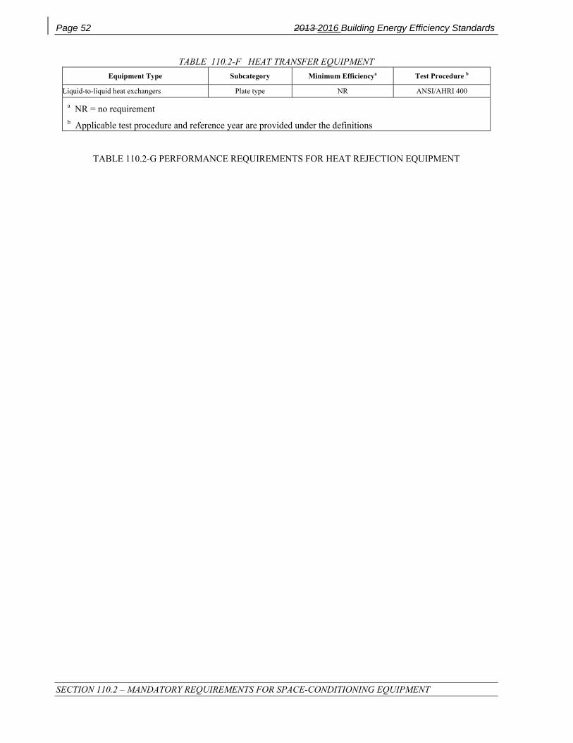
Page 52 2013 2016 Building Energy Efficiency Standards
SECTION 110.2 – MANDATORY REQUIREMENTS FOR SPACE-CONDITIONING EQUIPMENT
TABLE 110.2-F HEAT TRANSFER EQUIPMENT Equipment Type Subcategory Minimum Efficiencya Test Procedure b
Liquid-to-liquid heat exchangers Plate type NR ANSI/AHRI 400
a NR = no requirement b Applicable test procedure and reference year are provided under the definitions
TABLE 110.2-G PERFORMANCE REQUIREMENTS FOR HEAT REJECTION EQUIPMENT

2013 2016 Building Energy Efficiency Standards Page 53
SECTION 110.2 – MANDATORY REQUIREMENTS FOR SPACE-CONDITIONING EQUIPMENT
Equipment Type Total System Heat Rejection
Capacity at Rated Conditions
Subcategory or Rating Condition
Performance Required ,a ,b, c, d
Test Procedure e
Propeller or axial fan Open-circuit cooling towers
All 95°F entering water 85°F leaving water
75 °F entering air wb ≥ 42.1 gpm/hp
CTI ATC-105 and
CTI STD-201 CTI ATC-105
and CTI STD-201
CTI ATC-105S and
CTI STD-201 CTI ATC-105S
and CTI STD-201
Centrifugal fan Open-circuit cooling towers
All 95°F entering water 85°F leaving water
75 °F entering air wb ≥ 20.0 gpm/hp
Propeller or axial fan closed-circuit cooling towers
All 102°F entering water 90°F leaving water
75 °F entering air wb ≥ 14.0 gpm/hp
Centrifugal fan closed-circuit cooling towers
All 102°F entering water 90°F leaving water
75 °F entering air wb ≥ 7.0 gpm/hp
Propeller or axial fan evaporative condensers
All
" R-507A test fluid 165⁰F entering gas temp 105⁰F condensing temp 75⁰F entering air wb"
≥ 157,000 Btu/h • hp
CTI ATC-106
All
" Ammonia test fluid 140⁰F entering gas temp 96.3⁰F condensing temp
75⁰F entering air wb"
≥ 134,000 Btu/h • hp
Centrifugal fan evaporative condensers
All
" R-507A test fluid 165⁰F entering gas temp 105⁰F condensing temp 75⁰F entering air wb"
≥ 135,000 Btu/h • hp
All
" Ammonia test fluid 140⁰F entering gas temp 96.3⁰F condensing temp
75⁰F entering air wb"
≥ 110,000 Btu/h • hp
Air cooled condensers All
125°F condensing temperatureR22 test fluid
190°F entering gas temperature15°F subcooling
95°F entering drybulb
≥ 176,000 Btu/h·hp ANSI/AHRI 460
a For purposes of this table, open-circuit cooling tower performance is defined as the water flow rating of the tower at the given rated conditions divided by the fan motor nameplate power.
b For purposes of this table, closed-circuit cooling tower performance is defined as the process water flow rating of the tower at the given rated conditions divided by the sum of the fan motor nameplate rated power and the integral spray pump motor nameplate power .
c For purposes of this table air-cooled condenser performance is defined as the heat rejected from the refrigerant divided by the fan motor nameplate power.
d Open cooling towers shall be tested using the test procedures in CTI ATC-105. Performance of factory assembled open cooling towers shall be either certified as base models as specified in CTI STD-201 or verified by testing in the field by a CTI approved testing agency. Open factory assembled cooling towers with custom options added to a CTI certified base model for the purpose of safe maintenance or to reduce environmental or noise impact shall be rated at 90 percent of the CTI certified performance of the associated base model or at the manufacturer’s stated performance, whichever is less. Base models of open factory assembled cooling towers are open cooling towers configured in exact accordance with the Data of Record submitted to CTI as specified by CTI STD-201. There are no certification requirements for field erected cooling towers.
e Applicable test procedure and reference year are provided under the definitions.

Page 54 2013 2016 Building Energy Efficiency Standards
SECTION 110.2 – MANDATORY REQUIREMENTS FOR SPACE-CONDITIONING EQUIPMENT
TABLE 110.2-H Electrically Operated Variable Refrigerant Flow (VRF) Air Conditioners Minimum Efficiency Requirements
Equipment Type Size Category Heating Section Type
Sub-Category or Rating Condition Minimum Efficiency Test
Procedurea
VRF Air Conditioners, Air Cooled
<65,000 Btu/h All VRF Multi-split System 13.0 SEER
ANSI/AHRI 1230
≥65,000 Btu/h and <135,000 Btu/h
Electric Resistance (or
none)
VRF Multi-split System
11.2 EER
13.1 IEER b
≥135,000 Btu/h and <240,000 Btu/h
Electric Resistance (or
none)
VRF Multi-split System
11.0 EER
12.9 IEER b
≥240,000 Btu/h Electric
Resistance (or none)
VRF Multi-split System
10.0 EER
11.6 IEER b
a Applicable test procedure and reference year are provided under the definitions. b IEERs are only applicable to equipment with capacity control as per specified by ANSI/AHRI 1230 test
procedures.

2013 2016 Building Energy Efficiency Standards Page 55
SECTION 110.2 – MANDATORY REQUIREMENTS FOR SPACE-CONDITIONING EQUIPMENT
TABLE 110.2-I Electrically Operated Variable Refrigerant Flow Air-to-Air and Applied Heat Pumps - Minimum Efficiency Requirements
Equipment Type Size Category Heating Section Type
Sub-Category or Rating Condition
Minimum Efficiency Test Procedure b
VRF Air Cooled, (cooling mode)
<65,000 Btu/h All VRF Multi-split System 13.0 SEER
AHRI 1230
≥65,000 Btu/h and <135,000 Btu/h
Electric Resistance (or none)
VRF Multi-split System a 11.0 EER
12.9 IEER c
≥135,000 Btu/h and <240,000 Btu/h
Electric Resistance (or none)
VRF Multi-split System a 10.6 EER
12.3 IEER c
≥240,000 Btu/h Electric Resistance (or none)
VRF Multi-split System a 9.5 EER
11.0 IEER c
VRF Water source
(cooling mode)
<65,000 Btu/h All VRF Multi-split systems a
86ºF entering water
12.0 EER AHRI 1230
≥65,000 Btu/h and
<135,000 Btu/h
All VRF Multi-split System a
86ºF entering water
12.0 EER
≥135,000 Btu/h All VRF Multi-split System a
86ºF entering water
10.0 EER
VRF Groundwater source (cooling mode)
<135,000 Btu/h All VRF Multi-split System
59ºF entering water
16.2 EER AHRI 1230
≥135,000 Btu/h All VRF Multi-split System a
59ºF entering water
13.8 EER
VRF Ground source (cooling mode)
<135,000 Btu/h All VRF Multi-split System a
77ºF entering water
13.4 EER AHRI 1230
≥135,000 Btu/h All VRF Multi-split System a
77ºF entering water
11.0 EER

Page 56 2013 2016 Building Energy Efficiency Standards
SECTION 110.2 – MANDATORY REQUIREMENTS FOR SPACE-CONDITIONING EQUIPMENT
CONTINUED: TABLE 110.2-I Electrically Operated Variable Refrigerant Flow Air-to-Air and Applied Heat Pumps - Minimum Efficiency Requirements
Equipment Type Size Category Heating Section Type
Sub-Category or Rating Condition Minimum Efficiency Test
Procedure b
VRF Air Cooled
(heating mode)
<65,000 Btu/h
(cooling capacity)
- - - VRF Multi-split System 7.7 HSPF AHRI 1230
≥65,000 Btu/h and
<135,000 Btu/h
(cooling capacity)
- - - VRF Multi-split system
47ºF db/ 43ºF wb outdoor air
3.3 COP
VRF Multi-split system
17ºF db/15ºF wb outdoor air
2.25 COP
≥135,000 Btu/h
(cooling capacity)
- - - VRF Multi-split system
47ºF db/ 43ºF wb outdoor air
3.2 COP
VRF Multi-split system
17ºF db/15ºF wb outdoor air
2.05 COP
VRF Water source
(heating mode)
<135,000 Btu/h
(cooling capacity)
--- VRF Multi-split System
68ºF entering water
4.2 COP AHRI 1230
≥135,000 Btu/h
(cooling capacity)
--- VRF Multi-split System
68ºF entering water
3.9 COP
VRF Groundwater source
(heating mode)
<135,000 Btu/h
(cooling capacity)
--- VRF Multi-split System
50ºF entering water
3.6 COP AHRI 1230
≥135,000 Btu/h
(cooling capacity)
--- VRF Multi-split System
50ºF entering water
3.3 COP
VRF Ground source
(heating mode)
<135,000 Btu/h
(cooling capacity)
--- VRF Multi-split System
32ºF entering water
3.1 COP AHRI 1230
≥135,000 Btu/h
(cooling capacity)
--- VRF Multi-split System
32ºF entering water
2.8 COP
a Deduct 0.2 from the required EERs and IEERs for Variable Refrigerant Flow (VRF) Multi-split system units with a heating recovery section.
b Applicable test procedure and reference year are provided under the definitions.
c IEERs are only applicable to equipment with capacity control as per specified by ANSI/AHRI 1230 test procedures.
.

2013 2016 Building Energy Efficiency Standards Page 57
SECTION 110.2 – MANDATORY REQUIREMENTS FOR SPACE-CONDITIONING EQUIPMENT
TABLE 110.2-J Warm-Air Furnaces and Combination Warm-Air Furnaces/Air-Conditioning Units, Warm-Air Duct Furnaces, and Unit Heaters
Equipment Type Size Category (Input)
Subcategory or Rating Conditionb
Minimum Efficiencyd,e Test Procedurea
Warm-Air Furnace, Gas-Fired
< 225,000 Btu/h Maximum Capacityb 78% AFUE or 80%
Et DOE 10 CFR Part 430 or Section 2.39, Thermal
Efficiency, ANSI Z21.47
≥ 225,000 Btu/h Maximum Capacityb 80% Et Section 2.39, Thermal Efficiency, ANSI Z21.47
Warm-Air Furnace, oil-Fired
< 225,000 Btu/h Maximum Capacityb 78% AFUE or 80%
Et DOE 10 CFR Part 430 or Section 42, Combustion,
UL 727
≥ 225,000 Btu/h Maximum Capacityb 81% Et Section 42, Combustion, UL 727
Warm-Air Duct Furnaces, Gas-Fired All Capacities Maximum Capacityb 80% Ec Section 2.10, Efficiency, ANSI Z83.8
Warm-Air Unit Heaters, Gas-Fired All Capacities Maximum Capacityb 80% Ec Section 2.10, Efficiency, ANSI Z83.8
Warm-Air Unit Heaters, Oil-Fired All Capacities Maximum Capacityb 8081% Ec Section 40, Combustion, UL 731
a Applicable test procedure and reference year are provided under the definitions. b Compliance of multiple firing rate units shall be at maximum firing rate. c Combustion units not covered by NAECA (3-phase power or cooling capacity greater than or equal to 19 kW) may comply with either rating. d Et= thermal efficiency. Units must also include an interrupted or intermittent ignition device (IID), have jacket losses not exceeding 0.75% of the input rating, and have either power venting or a flue damper. A vent damper is an acceptable alternative to a flue damper for those furnaces where combustion air is drawn from the conditioned space. e Ec= combustion efficiency (100% less flue losses). See test procedure for detailed discussion. f As of August 8, 2008, according to the Energy Policy Act of 2005, units must also include interrupted or intermittent ignition device (IID) and have either power venting or an automatic flue damper.
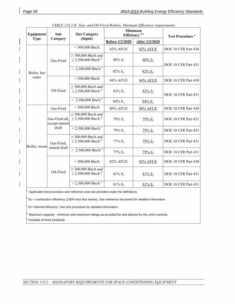
Page 58 2013 2016 Building Energy Efficiency Standards
SECTION 110.2 – MANDATORY REQUIREMENTS FOR SPACE-CONDITIONING EQUIPMENT
TABLE 110.2-K Gas- and Oil-Fired Boilers, Minimum Efficiency requirements
Equipment Type
Sub Category
Size Category (Input)
Minimum Efficiency b,c Test Procedure a
Before 3/2/2020 After 3/2/2020
Boiler, hot water
Gas-Fired
< 300,000 Btu/h 82% AFUE 82% AFUE DOE 10 CFR Part 430
≥ 300,000 Btu/h and ≤ 2,500,000 Btu/h d 80% Et 80% Et
DOE 10 CFR Part 431> 2,500,000 Btu/h e
82% Ec 82% Ec
Oil-Fired
< 300,000 Btu/h 84% AFUE 84% AFUE DOE 10 CFR Part 430
≥ 300,000 Btu/h and ≤ 2,500,000 Btu/h d 82% Et 82% Et
DOE 10 CFR Part 431> 2,500,000 Btu/h e 84% Ec 84% Ec
Boiler, steam
Gas-Fired < 300,000 Btu/h 80% AFUE 80% AFUE DOE 10 CFR Part 430
Gas-Fired all, except natural
draft
≥ 300,000 Btu/h and ≤ 2,500,000 Btu/h d 79% Et 79% Et DOE 10 CFR Part 431
> 2,500,000 Btu/h e 79% Et 79% Et DOE 10 CFR Part 431
Gas-Fired, natural draft
≥ 300,000 Btu/h and ≤ 2,500,000 Btu/h d 77% Et 79% Et DOE 10 CFR Part 431
> 2,500,000 Btu/h e 77% Et 79% Et DOE 10 CFR Part 431
Oil-Fired
< 300,000 Btu/h 82% AFUE 82% AFUE DOE 10 CFR Part 430
≥ 300,000 Btu/h and ≤ 2,500,000 Btu/h d 81% Et 81% Et DOE 10 CFR Part 431
> 2,500,000 Btu/h e 81% Et 81% Et DOE 10 CFR Part 431a Applicable test procedure and reference year are provided under the definitions.
b Ec = combustion efficiency (100% less flue losses) .See reference document for detailed information.
c Et= thermal efficiency. See test procedure for detailed information.
d Maximum capacity - minimum and maximum ratings as provided for and allowed by the unit’s controls. e Included oil-fired (residual).

2013 2016 Building Energy Efficiency Standards Page 59
SECTION 110.3 – MANDATORY REQUIREMENTS FOR SERVICE WATER-HEATING SYSTEMS AND EQUIPMENT
SECTION 110.3 – MANDATORY REQUIREMENTS FOR SERVICE WATER-HEATING SYSTEMS AND EQUIPMENT (a) Certification by Manufacturers. Any service water-heating system or equipment may be installed only if the
manufacturer has certified that the system or equipment complies with all of the requirements of this subsection for that system or equipment.
1. Temperature controls for service waterheating systems. Service water-heating systems shall be equipped with automatic temperature controls capable of adjustment from the lowest to the highest acceptable temperature settings for the intended use as listed in Table 3, Chapter 50 of the ASHRAE Handbook, HVAC Applications Volume.
EXCEPTION to Section 110.3(a)1: Residential occupancies.
(b) Efficiency. Equipment shall meet the applicable requirements of the Appliance Efficiency Regulations as required by Section 110.1, subject to the following:
1. If more than one standard is listed in the Appliance Efficiency Regulations, the equipment shall meet all the standards listed; and
2. If more than one test method is listed in the Appliance Efficiency Regulations, the equipment shall comply with the applicable standard when tested with each test method; and
3. Where equipment can serve more than one function, such as both heating and cooling, or both space heating and water heating, it shall comply with all the requirements applicable to each function; and
4. Where a requirement is for equipment rated at its "maximum rated capacity" or "minimum rated capacity," the capacity shall be as provided for and allowed by the controls, during steady-state operation.
(c) Installation. Any service water-heating system or equipment may be installed only if the system or equipment complies with all of the applicable requirements of this subsection for the system or equipment.
1. Outlet temperature controls. On systems that have a total capacity greater than 167,000 Btu/hr, outlets that require higher than service water temperatures as listed in the ASHRAE Handbook, Applications Volume, shall have separate remote heaters, heat exchangers, or boosters to supply the outlet with the higher temperature.
2. Controls for hot water distribution systems. Service hot water systems with circulating pumps or with electrical heat trace systems shall be capable of automatically turning off the system.
3. Temperature controls for public lavatories. The controls shall limit the outlet temperature at the fixtures to 110°F.
4. Insulation. Unfired service water heater storage tanks and backup tanks for solar water-heating systems shall have:
A. External insulation with an installed R-value of at least R-12; or
B. Internal and external insulation with a combined R-value of at least R-16; or
C. The heat loss of the tank surface based on an 80°F water-air temperature difference shall be less than 6.5 Btu per hour per square foot.
5. Water Heating Recirculation Loops Serving Multiple Dwelling Units, High-Rise Residential, Hotel/Motel and Nonresidential Occupancies. A water heating recirculation loop is a type of hot water distribution system that reduces the time needed to deliver hot water to fixtures that are distant from the water heater, boiler or other water heating equipment. The recirculation loop is comprised of a supply portion, connected to branches that serve multiple dwelling units, guest rooms, or fixtures and a return portion that completes the loop back to the water heating equipment. A water heating recirculation loop shall meet the following requirements:

Page 60 2013 2016 Building Energy Efficiency Standards
SECTION 110.3 – MANDATORY REQUIREMENTS FOR SERVICE WATER-HEATING SYSTEMS AND EQUIPMENT
A. Air release valve or vertical pump installation. An automatic air release valve shall be installed on the recirculation loop piping on the inlet side of the recirculation pump and no more than 4 feet from the pump. This valve shall be mounted on top of a vertical riser at least 12” in length and shall be accessible for replacement and repair. Alternatively, the pump shall be installed on a vertical section of the return line.
B. Recirculation loop backflow prevention. A check valve or similar device shall be located between the recirculation pump and the water heating equipment to prevent water from flowing backwards though the recirculation loop.
C. Equipment for pump priming. A hose bibb shall be installed between the pump and the water heating equipment. An isolation valve shall be installed between the hose bibb and the water heating equipment. This hose bibb is used for bleeding air out of the pump after pump replacement.
D. Pump isolation valves. Isolation valves shall be installed on both sides of the pump. These valves may be part of the flange that attaches the pump to the pipe. One of the isolation valves may be the same isolation valve as in Item C.
E. Cold water supply and recirculation loop connection to hot water storage tank. Storage water heaters and boilers shall be plumbed in accordance with the manufacturer’s specifications. The cold water piping and the recirculation loop piping shall not be connected to the hot water storage tank drain port.
F. Cold water supply backflow prevention. A check valve shall be installed on the cold water supply line between the hot water system and the next closest tee on the cold water supply line. The system shall comply with the expansion tank requirements as described in the California Plumbing Code Section 608.3.
6. Service water heaters in state buildings. Any newly constructed building constructed by the State shall derive its service water heating from a system that provides at least 60 percent of the energy needed for service water heating from site solar energy or recovered energy.
EXCEPTION to Section 110.3(c)6: Buildings for which the state architect determines that service water heating from site solar energy or recovered energy is economically or physically infeasible.
7. Isolation valves. Instantaneous water heaters with an input rating greater than 6.8 kBTU/hr (2 kW) shall have isolation valves on both the cold water supply and the hot water pipe leaving the water heater, and hose bibbs or other fittings on each valve for flushing the water heater when the valves are closed.

2013 2016 Building Energy Efficiency Standards Page 61
SECTION 110.4 – MANDATORY REQUIREMENTS FOR POOL AND SPA SYSTEMS AND EQUIPMENT
SECTION 110.4 – MANDATORY REQUIREMENTS FOR POOL AND SPA SYSTEMS AND EQUIPMENT (a) Certification by Manufacturers. Any pool or spa heating system or equipment may be installed only if the
manufacturer has certified that the system or equipment has all of the following:
1. Efficiency. A thermal efficiency that complies with the Appliance Efficiency Regulations; and
2. On-off switch. A readily accessible on-off switch, mounted on the outside of the heater that allows shutting off the heater without adjusting the thermostat setting; and
3. Instructions. A permanent, easily readable, and weatherproof plate or card that gives instruction for the energy efficient operation of the pool or spa heater and for the proper care of pool or spa water when a cover is used; and
4. Electric resistance heating. No electric resistance heating; and
EXCEPTION 1 to Section 110.4(a)4: Listed package units with fully insulated enclosures, and with tight-fitting covers that are insulated to at least R-6.
EXCEPTION 2 to Section 110.4(a)4: Pools or spas deriving at least 60 percent of the annual heating energy from site solar energy or recovered energy.
(b) Installation. Any pool or spa system or equipment shall be installed with all of the following:
1. Piping. At least 36 inches of pipe shall be installed between the filter and the heater or dedicated suction and return lines, or built-in or built-up connections shall be installed to allow for the future addition of solar heating equipment; and
2. Covers. A cover for outdoor pools or outdoor spas that have a heat pump or gas heater.
3. Directional inlets and time switches for pools. If the system or equipment is for a pool:
i. The pool shall have directional inlets that adequately mix the pool water; and
ii. A time switch or similar control mechanism shall be installed as part of a pool water circulation control system that will allow all pumps to be set or programmed to run only during the off-peak electric demand period and for the minimum time necessary to maintain the water in the condition required by applicable public health standards.

Page 62 2013 2016 Building Energy Efficiency Standards
SECTION 110.5 – NATURAL GAS CENTRAL FURNACES, COOKING EQUIPMENT, AND POOL AND SPA HEATERS: PILOT LIGHTS PROHIBITED
SECTION 110.5 – NATURAL GAS CENTRAL FURNACES, COOKING EQUIPMENT, AND POOL AND SPA HEATERS: PILOT LIGHTS PROHIBITED Any natural gas system or equipment listed below may be installed only if it does not have a continuously burning pilot light:
(a) Fan-type central furnaces.
(b) Household cooking appliances.
EXCEPTION to Section 110.5(b): Household cooking appliances without an electrical supply voltage connection and in which each pilot consumes less than 150 Btu/hr.
(c) Pool heaters.
(d) Spa heaters.
2013 Building Energy Efficiency Standards Page 63
SECTION 110.6 – MANDATORY REQUIREMENTS FOR FENESTRATION PRODUCTS AND EXTERIOR DOORS
SECTION 110.6 – MANDATORY REQUIREMENTS FOR FENESTRATION PRODUCTS AND EXTERIOR DOORS (a) Certification of Fenestration Products and Exterior Doors other than Field-fabricated. Any fenestration
product and exterior door, other than field-fabricated fenestration products and field-fabricated exterior doors, may be installed only if the manufacturer has certified to the Commission, or if an independent certifying organization approved by the Commission has certified that the product complies with all of the applicable requirements of this subsection.
1. Air leakage. Manufactured fenestration products and exterior doors shall have air infiltration rates not exceeding 0.3 cfm/ft² of window area, 0.3 cfm/ft² of door area for residential doors, 0.3 cfm/ft² of door area for nonresidential single doors (swinging and sliding), and 1.0 cfm/ft² for nonresidential double doors (swinging), when tested according to NFRC-400 or ASTM E283 at a pressure differential of 75 pascals (or 1.57 pounds/ft²), incorporated herein by reference.
Note: Pet doors must also meet 0.3 cfm/ft² when tested according to ASTM E283 at 75 pascals (or 1.57 pounds/ft²).
EXCEPTION to Section 110.6(a)1: Field-fabricated fenestration and field-fabricated exterior doors.
2. U-factor. The fenestration product’s U-factor shall be rated in accordance with NFRC 100, or use the applicable default U-factor set forth in TABLE 110.6-A.
EXCEPTION 1 to Section 110.6(a)2: If the fenestration product is a vertical skylight or is a site-built fenestration product in a building covered by the nonresidential standards with less than 1,000 square feet of site-built fenestration, the default U-factor may be calculated as set forth in Reference Nonresidential Appendix NA6.
EXCEPTION 2 to Section 110.6(a)2: If the fenestration product is an alteration consisting of any area replacement of glass in a skylight product or in a vertical site-built fenestration product, in a building covered by the nonresidential standards, the default U-factor may be calculated as set forth in Reference Nonresidential Appendix NA6.
3. Solar Heat Gain Coefficient (SHGC). The fenestration product’s SHGC shall be rated in accordance with NFRC 200, or use the applicable default SHGC set forth in TABLE 110.6-B.
EXCEPTION 1 to Section 110.6(a)3: If the fenestration product is a skylight or is a vertical site-built fenestration product in a building covered by the nonresidential standards with less than 1,000 square feet of site-built fenestration, the default SHGC may be calculated as set forth in Reference Nonresidential Appendix NA6.
EXCEPTION 2 to Section 110.6(a)3: If the fenestration product is an alteration consisting of any area replacement of glass in a skylight product or in a vertical site-built fenestration product, in a building covered by the nonresidential standards, the default SHGC may be calculated as set forth in Reference Nonresidential Appendix NA6.
4. Visible Transmittance (VT). The fenestration product’s VT shall be rated in accordance with NFRC 200 or ASTM E972, for tubular skylights VT shall be rated using NFRC 203.
EXCEPTION 1 to Section 110.6(a)4: If the fenestration product is a skylight or is a vertical site-built fenestration product in a building covered by the nonresidential standards with less than 1,000 square feet of site-built fenestration, the default VT may be calculated as set forth in Reference Nonresidential Appendix NA6.
EXCEPTION 2 to Section 110.6(a)4: If the fenestration product is an alteration consisting of any area; replacement of glass in a skylight product or in a vertical site-built fenestration product in a building covered by the nonresidential standards, the default VT may be calculated as set forth in Reference Nonresidential Appendix NA6.
5. Labeling. Fenestration products shall:
Page 64 2013 2016 Building Energy Efficiency Standards
SECTION 110.6 – MANDATORY REQUIREMENTS FOR FENESTRATION PRODUCTS AND EXTERIOR DOORS
A. Have a temporary label for manufactured fenestration products or a label certificate when the Component Modeling Approach (CMA) is used and for site-built fenestration meeting the requirements of Section 10-111(a)1. The temporary label listing the certified U-factor, SHGC and VT, shall not be removed before inspection by the enforcement agency. The temporary label shall certify that the air leakage requirements of Section 110.6(a)1 are met for each product line; and
B. Have a permanent label or a label certificate when the Component Modeling Approach (CMA) is used and for site-built fenestration meeting the requirements of Section 10-111(a)2 if the product is rated using NFRC procedures.
6. Fenestration Acceptance Requirements. Before an occupancy permit is granted, site-built fenestration products in other than low-rise residential buildings shall be certified as meeting the Acceptance Requirements for Code Compliance, as specified in the Reference Nonresidential Appendix NA7 to ensure that site-built fenestration meet Standards requirements, including a matching label certificate for product(s) installed and be readily accessible at the project location. A Certificate of Acceptance certifying that the fenestration product meets the acceptance requirements shall be completed, signed and submitted to the enforcement agency.
EXCEPTION to Section 110.6(a): Fenestration products removed and reinstalled as part of a building alteration or addition.
(b) Installation of Field-fabricated Fenestration and Exterior Doors. Field-fabricated fenestration and field-fabricated exterior doors may be installed only if the compliance documentation has demonstrated compliance for the installation using U-factors from TABLE 110.6-A and SHGC values from TABLE 110.6-B. Field-fabricated fenestration and field-fabricated exterior doors shall be caulked between the fenestration products or exterior door and the building, and shall be weatherstripped.
EXCEPTION to Section 110.6(b): Unframed glass doors and fire doors need not be weather stripped or caulked.

2013 Building Energy Efficiency Standards Page 65
SECTION 110.6 – MANDATORY REQUIREMENTS FOR FENESTRATION PRODUCTS AND EXTERIOR DOORS
TABLE 110.6-A DEFAULT FENESTRATION PRODUCT U-FACTORS FRAME PRODUCT TYPE SINGLE PANE 3, 4
U-FACTOR DOUBLE PANE 1, 3, 4
U-FACTOR GLASS BLOCK 2,3
U-FACTOR
Metal
Operable 1.28 0.79 0.87
Fixed 1.19 0.71 0.72
Greenhouse/garden window
2.26 1.40 N.A.
Doors 1.25 0.77 N.A.
Skylight 1.98 1.30 N.A.
Metal, Thermal Break
Operable N.A. 0.66 N.A.
Fixed N.A. 0.55 N.A.
Greenhouse/garden window
N.A. 1.12 N.A.
Doors N.A. 0.59 N.A.
Skylight N.A. 1.11 N.A.
Nonmetal
Operable 0.99 0.58 0.60
Fixed 1.04 0.55 0.57
Doors 0.99 0.53 N.A.
Greenhouse/garden windows
1.94 1.06 N.A.
Skylight 1.47 0.84 N.A.
1. For all dual-glazed fenestration products, adjust the listed U-factors as follows:
a. Add 0.05 for products with dividers between panes if spacer is less than 7/16 inch wide.
b. Add 0.05 to any product with true divided lite (dividers through the panes).
2. Translucent or transparent panels shall use glass block values when not rated by NFRC 100.
3. Visible Transmittance (VT) shall be calculated by using Reference Nonresidential Appendix NA6.
4. Windows with window film applied that is not rated by NFRC 100 shall use the default values from this table.

Page 66 2013 2016 Building Energy Efficiency Standards
SECTION 110.7 – MANDATORY REQUIREMENTS TO LIMIT AIR LEAKAGE
TABLE 110.6-B DEFAULT SOLAR HEAT GAIN COEFFICIENT (SHGC)
FRAME TYPE PRODUCT GLAZING
FENESTRATION PRODUCT SHGC
Single Pane2,3 SHGC
Double Pane2,3 SHGC
Glass Block1,2 SHGC
Metal
Operable Clear 0.80 0.70 0.70
Fixed Clear 0.83 0.73 0.73
Operable Tinted 0.67 0.59 N.A.
Fixed Tinted 0.68 0.60 N.A.
Metal, Thermal Break
Operable Clear N.A. 0.63 N.A.
Fixed Clear N.A. 0.69 N.A.
Operable Tinted N.A. 0.53 N.A.
Fixed Tinted N.A. 0.57 N.A.
Nonmetal
Operable Clear 0.74 0.65 0.70
Fixed Clear 0.76 0.67 0.67
Operable Tinted 0.60 0.53 N.A.
Fixed Tinted 0.63 0.55 N.A.
1 Translucent or transparent panels shall use glass block values when not rated by NFRC 200.
2. Visible Transmittance (VT) shall be calculated by using Reference Nonresidential Appendix NA6.
3. Windows with window film applied that is not rated by NFRC 200 shall use the default values from this table
SECTION 110.7 – MANDATORY REQUIREMENTS TO LIMIT AIR LEAKAGE All joints, penetrations and other openings in the building envelope that are potential sources of air leakage shall be caulked, gasketed, weather stripped, or otherwise sealed to limit infiltration and exfiltration.

2013 Building Energy Efficiency Standards Page 67
SECTION 110.8 – MANDATORY REQUIREMENTS FOR INSULATION, ROOFING PRODUCTS AND RADIANT BARRIERS
SECTION 110.8 – MANDATORY REQUIREMENTS FOR INSULATION, ROOFING PRODUCTS AND RADIANT BARRIERS (a) Insulation Certification by Manufacturers. Any insulation shall be certified by Department of Consumer
Affairs, Bureau of Home Furnishing and Thermal Insulation that the insulation conductive thermal performance is approved pursuant to the California Code of Regulations, Title 24, Part 12, Chapters 12-13, Article 3, “Standards for Insulating Material.”
(b) Installation of Urea Formaldehyde Foam Insulation. Urea formaldehyde foam insulation may be applied or installed only if:
1. It is installed in exterior side walls; and
2. A four-mil-thick plastic polyethylene vapor retarder or equivalent plastic sheathing vapor retarder is installed between the urea formaldehyde foam insulation and the interior space in all applications.
(c) Flame Spread Rating of Insulation. All insulating material shall be installed in compliance with the flame spread rating and smoke density requirements of the CBC.
(d) Installation of Insulation in Existing Buildings. Insulation installed in an existing attic, or on an existing duct or water heater, shall comply with the applicable requirements of Subsections 1, 2, and 3 below. If a contractor installs the insulation, the contractor shall certify to the customer, in writing, that the insulation meets the applicable requirements of Subsections 1, 2, and 3 below.
1. Attics. If insulation is installed in the existing attic of a low-rise residential building, the R-value of the total amount of insulation (after addition of insulation to the amount, if any, already in the attic) shall meet the requirements of Section 150.0(a).
EXCEPTION to Section 110.8(d)1: Where the accessible space in the attic is not large enough to accommodate the required R-value, the entire accessible space shall be filled with insulation provided such installation does not violate Section 1203.2 of Title 24, Part 2.
2. Water heaters. If external insulation is installed on an existing unfired water storage tank or on an existing back-up tank for a solar water-heating system, it shall have an R-value of at least R-12, or the heat loss of the tank surface based on an 80°F water-air temperature difference shall be less than 6.5 Btu per hour per square foot.
3. Ducts. If insulation is installed on an existing space-conditioning duct, it shall comply with Section 605.0 of the CMC.
(e) RESERVED Insulation Placement on Roof/Ceilings. Insulation installed to limit heat loss and gain through the top of conditioned spaces shall comply with the following:
1. Insulation shall be installed in direct contact with a continuous roof or ceiling which is sealed to limit infiltration and exfiltration as specified in Section 110.7, including but not limited to placing insulation either above or below the roof deck or on top of a drywall ceiling; and
2. When insulation is installed at the roof in nonresidential buildings, fixed vents or openings to the outdoors or to unconditioned spaces shall not be installed and the space between the ceiling and the roof is either directly or indirectly conditioned space and shall not be considered an attic for the purposes of complying with CBC attic ventilation requirements; and
3. Insulation shall not be placed on top of a suspended ceiling with removable ceiling panels to meet the Roof/Ceiling requirement of Sections 120.7, 140.3 and 141.0; and
EXCEPTION to Section 110.8(e)3: When there are conditioned spaces with a combined floor area no greater than 2,000 square feet in an otherwise unconditioned building, and when the average height of the space between the ceiling and the roof over these spaces is greater than 12 feet, insulation placed in direct contact with a suspended ceiling with removable ceiling panels shall be an acceptable method of reducing heat loss from a conditioned space and shall be accounted for in heat loss calculations.
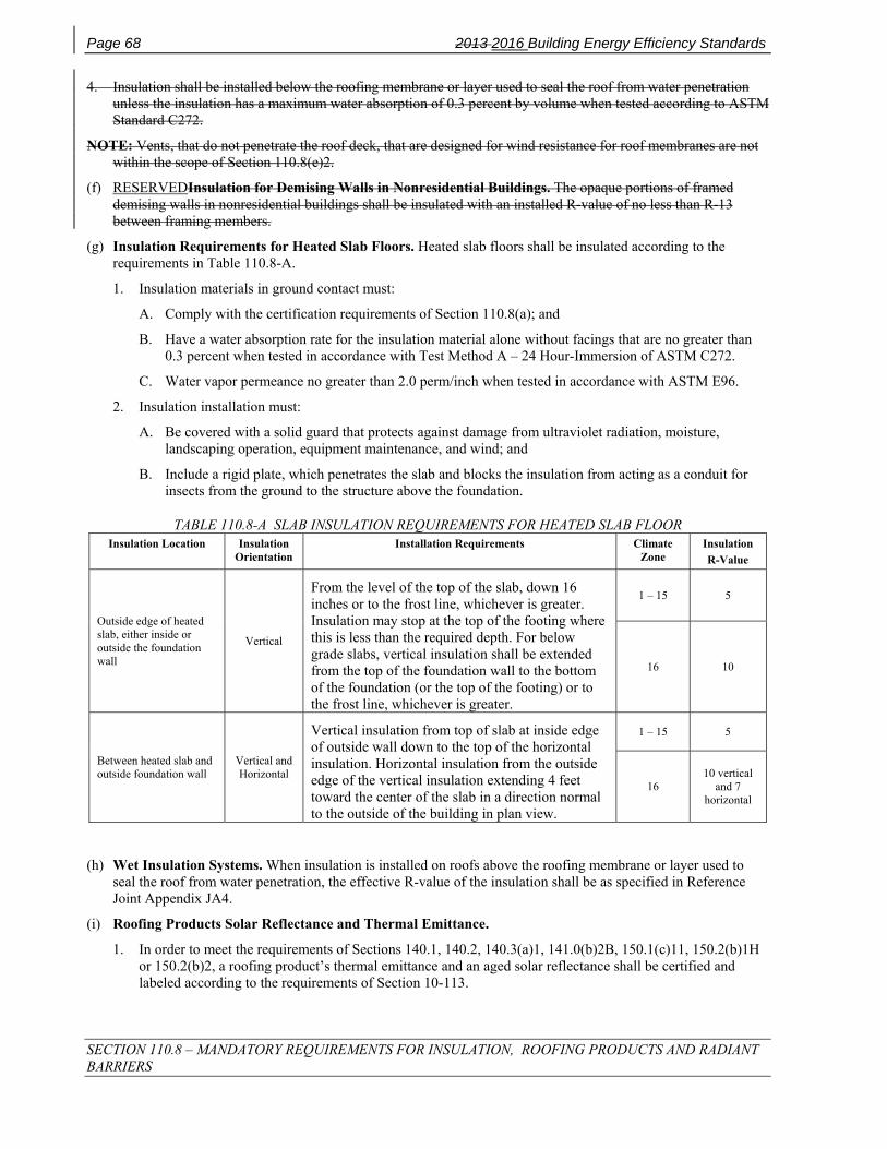
Page 68 2013 2016 Building Energy Efficiency Standards
SECTION 110.8 – MANDATORY REQUIREMENTS FOR INSULATION, ROOFING PRODUCTS AND RADIANT BARRIERS
4. Insulation shall be installed below the roofing membrane or layer used to seal the roof from water penetration unless the insulation has a maximum water absorption of 0.3 percent by volume when tested according to ASTM Standard C272.
NOTE: Vents, that do not penetrate the roof deck, that are designed for wind resistance for roof membranes are not within the scope of Section 110.8(e)2.
(f) RESERVEDInsulation for Demising Walls in Nonresidential Buildings. The opaque portions of framed demising walls in nonresidential buildings shall be insulated with an installed R-value of no less than R-13 between framing members.
(g) Insulation Requirements for Heated Slab Floors. Heated slab floors shall be insulated according to the requirements in Table 110.8-A.
1. Insulation materials in ground contact must:
A. Comply with the certification requirements of Section 110.8(a); and
B. Have a water absorption rate for the insulation material alone without facings that are no greater than 0.3 percent when tested in accordance with Test Method A – 24 Hour-Immersion of ASTM C272.
C. Water vapor permeance no greater than 2.0 perm/inch when tested in accordance with ASTM E96.
2. Insulation installation must:
A. Be covered with a solid guard that protects against damage from ultraviolet radiation, moisture, landscaping operation, equipment maintenance, and wind; and
B. Include a rigid plate, which penetrates the slab and blocks the insulation from acting as a conduit for insects from the ground to the structure above the foundation.
TABLE 110.8-A SLAB INSULATION REQUIREMENTS FOR HEATED SLAB FLOOR Insulation Location Insulation
Orientation Installation Requirements Climate
Zone Insulation R-Value
Outside edge of heated slab, either inside or outside the foundation wall
Vertical
From the level of the top of the slab, down 16 inches or to the frost line, whichever is greater. Insulation may stop at the top of the footing where this is less than the required depth. For below grade slabs, vertical insulation shall be extended from the top of the foundation wall to the bottom of the foundation (or the top of the footing) or to the frost line, whichever is greater.
1 – 15 5
16 10
Between heated slab and outside foundation wall
Vertical and Horizontal
Vertical insulation from top of slab at inside edge of outside wall down to the top of the horizontal insulation. Horizontal insulation from the outside edge of the vertical insulation extending 4 feet toward the center of the slab in a direction normal to the outside of the building in plan view.
1 – 15 5
16 10 vertical
and 7 horizontal
(h) Wet Insulation Systems. When insulation is installed on roofs above the roofing membrane or layer used to seal the roof from water penetration, the effective R-value of the insulation shall be as specified in Reference Joint Appendix JA4.
(i) Roofing Products Solar Reflectance and Thermal Emittance.
1. In order to meet the requirements of Sections 140.1, 140.2, 140.3(a)1, 141.0(b)2B, 150.1(c)11, 150.2(b)1H or 150.2(b)2, a roofing product’s thermal emittance and an aged solar reflectance shall be certified and labeled according to the requirements of Section 10-113.

2013 Building Energy Efficiency Standards Page 69
SECTION 110.8 – MANDATORY REQUIREMENTS FOR INSULATION, ROOFING PRODUCTS AND RADIANT BARRIERS
EXCEPTION 1 to Section 110.8(i)1: Roofing products that are not certified according to Section 10-113 shall assume the following default aged solar reflectance/thermal emittance values:
A. For asphalt shingles: 0.08/0.75
B. For all other roofing products: 0.10/0.75
2. If CRRC testing for an aged solar reflectance is not available for any roofing products, the aged value shall be derived from the CRRC initial value using the equation ρaged=[0.2+β[ρinitial-0.2], where ρinitial = the initial solar reflectance and soiling resistance β is listed by product type in TABLE 110.8-B.
TABLE 110.8-B VALUES OF SOILING RESISTANCE β BY PRODUCT TYPE Product Type CRRC Product Category β
Field-Applied Coating Field-Applied Coating 0.65
Other
Not A Field-Applied Coating 0.70
3. Solar Reflectance Index (SRI), calculated as specified by ASTM E 1980-01, may be used as an alternative to thermal emittance and an aged solar reflectance when complying with the requirements of Sections 140.1, 140.2, 140.3(a)1, 141.0(b)2B, 150.1(c)11, 150.2(b)1H,or 150.2(b)2. SRI calculations shall be based on moderate wind velocity of 2-6 meters per second. The SRI shall be calculated based on the aged reflectance value of the roofing products.
4. Liquid applied roof coatings applied to low-sloped roofs in the field as the top surface of a roof covering shall:
A. Be applied across the entire roof surface to meet the dry mil thickness or coverage recommended by the coating manufacturer, taking into consideration the substrate on which the coating is applied, and
B. Meet the minimum performance requirements listed in TABLE 110.8-C or the minimum performance requirements of ASTM C836, D3468, D6083, or D6694, whichever are appropriate to the coating material.
EXCEPTION 1 to Section 110.8(i)4B: Aluminum-pigmented asphalt roof coatings shall meet the requirements of ASTM D2824 or ASTM D6848 and be installed as specified by ASTM D3805.
EXCEPTION 2 to Section 110.8(i)4B: Cement-based roof coatings shall contain a minimum of 20 percent cement and shall meet the requirements of ASTM C1583, ASTM D822, and ASTM D5870.
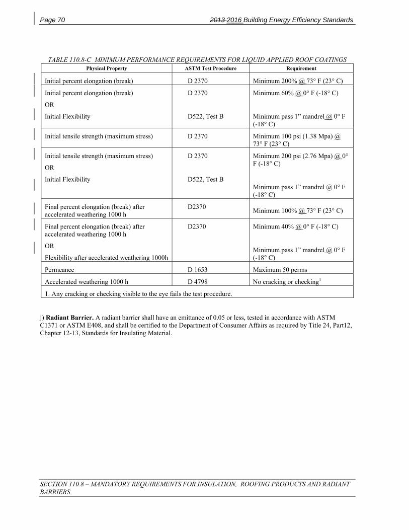
Page 70 2013 2016 Building Energy Efficiency Standards
SECTION 110.8 – MANDATORY REQUIREMENTS FOR INSULATION, ROOFING PRODUCTS AND RADIANT BARRIERS
TABLE 110.8-C MINIMUM PERFORMANCE REQUIREMENTS FOR LIQUID APPLIED ROOF COATINGS Physical Property ASTM Test Procedure Requirement
Initial percent elongation (break) D 2370 Minimum 200% @ 73° F (23° C)
Initial percent elongation (break)
OR
Initial Flexibility
D 2370
D522, Test B
Minimum 60% @ 0° F (-18° C)
Minimum pass 1” mandrel @ 0° F (-18° C)
Initial tensile strength (maximum stress) D 2370 Minimum 100 psi (1.38 Mpa) @ 73° F (23° C)
Initial tensile strength (maximum stress)
OR
Initial Flexibility
D 2370
D522, Test B
Minimum 200 psi (2.76 Mpa) @ 0° F (-18° C)
Minimum pass 1” mandrel @ 0° F (-18° C)
Final percent elongation (break) after accelerated weathering 1000 h
D2370 Minimum 100% @ 73° F (23° C)
Final percent elongation (break) after accelerated weathering 1000 h
OR
Flexibility after accelerated weathering 1000h
D2370 Minimum 40% @ 0° F (-18° C)
Minimum pass 1” mandrel @ 0° F (-18° C)
Permeance D 1653 Maximum 50 perms
Accelerated weathering 1000 h D 4798 No cracking or checking1
1. Any cracking or checking visible to the eye fails the test procedure.
j) Radiant Barrier. A radiant barrier shall have an emittance of 0.05 or less, tested in accordance with ASTM C1371 or ASTM E408, and shall be certified to the Department of Consumer Affairs as required by Title 24, Part12, Chapter 12-13, Standards for Insulating Material.

2013 Building Energy Efficiency Standards Page 71
SECTION 110.9 – MANDATORY REQUIREMENTS FOR LIGHTING CONTROL DEVICES AND SYSTEMS, BALLASTS, AND LUMINAIRES
SECTION 110.9 – MANDATORY REQUIREMENTS FOR LIGHTING CONTROL DEVICES AND SYSTEMS, BALLASTS, AND LUMINAIRES
(a) All lighting control devices and systems, ballasts, and luminaires subject to the requirements of Section 110.9 shall meet the following requirements:
1. Shall be installed only if the lighting control device or system, ballast, or luminaire complies with all of the applicable requirements of Section 110.9.
2. Lighting controls may be individual devices (Self Contained Lighting Control) or systems (Lighting Control Systems) consisting of two or more components.
3. Self Contained Lighting Controls, as defined in Section 100.1, shall be certified by the Manufacturer as required by the Title 20 Appliance Efficiency Regulations.
4. Lighting Control Systems, as defined in Section 100.1, shall be a fully functional lighting control system complying with the applicable requirements in Section 110.9(b), and shall meet the Lighting Control Installation requirements in Section 130.4.
5. If indicator lights are integral to a lighting control system, they shall consume no more than one watt of power per indicator light.
(b) All Installed Lighting Control Systems listed in Section 110.9(b) shall comply with the requirements listed below; and all components of the system considered together as installed shall meet all applicable requirements for the application for which they are installed as required in Sections 130.0 through 130.5, Sections 140.6 through 140.8, Section 141.0, and Section 150.0(k).
1. Time-Switch Lighting Controls
A. Automatic Time-Switch Controls shall meet all requirements for Automatic Time Switch Control devices in the Title 20 Appliance Efficiency Regulations.
B. Astronomical Time-Switch Controls shall meet all requirements for Astronomical Time-Switch Control devices in the Title 20 Appliance Efficiency Regulations.
C. Multi-Level Astronomical Time-Switch Controls, in addition to meeting all of the requirements for Astronomical Time-Switch Controls, shall include at least 2 separately programmable steps per zone.
D. Outdoor Astronomical Time-Switch Controls, in addition to meeting all of the requirements for Astronomical Time-Switch Controls, shall have setback functions that allow the lighting on each controlled channel to be switched or dimmed to lower levels. The set back functions shall be capable of being programmed by the user for at least one specific time of day.
2. Daylighting Controls
A. Automatic Daylight Controls shall meet all requirements for Automatic Daylight Control devices in the Title 20 Appliance Efficiency Regulations.
B. Photo Controls shall meet all requirements for Photo Control devices in the Title 20 Appliance Efficiency Regulations.
3. Dimmers shall meet all requirements for Dimmer Control devices in the Title 20 Appliance Efficiency Regulations.
4. Occupant Sensing Controls: Occupant, Motion, and Vacancy Sensor Controls shall meet the following requirements:
A. Occupant Sensors shall meet all applicable requirements for Occupant Sensor Control devices in the Title 20 Appliance Efficiency Regulations.

Page 72 2013 2016 Building Energy Efficiency Standards
SECTION 110.9 – MANDATORY REQUIREMENTS FOR LIGHTING CONTROL DEVICES AND SYSTEMS, BALLASTS, AND LUMINAIRES
B. Motion Sensors shall meet all applicable requirements for Motion Sensor Controls devices in the Title 20 Appliance Efficiency Regulations.
C. Vacancy Sensors shall meet all applicable requirements for Vacancy Sensor Controls devices in the Title 20 Appliance Efficiency Regulations.
D. Partial-ON Sensors shall meet all applicable requirements for partial on sensing devices in the Title 20 Appliance Efficiency Regulations.
E. Partial-OFF Sensors shall meet all applicable requirements for partial off sensing devices in the Title 20 Appliance Efficiency Regulations.
F. All Occupant Sensing Control types shall be programmed to turn OFF all or part of the lighting no longer than 20 minutes after the space is vacated of occupants, as specified by the applicable controls requirements of Section 130.1(c).
EXCEPTION to Section 110.9(b)4: Occupant Sensing Control systems may consist of a combination of single or multi-level Occupant, Motion, or Vacancy Sensor Controls, provided that components installed to comply with manual-on requirements shall not be capable of conversion by the user from manual-on to automatic-on functionality.
5. Part-Night Outdoor Lighting Controls, as defined in Section 100.1, shall meet all of the following requirements:
A. Have sunrise and sunset prediction accuracy within +/- 15 minutes and timekeeping accuracy within five minutes per year; and
B. Have the ability to setback or turn off lighting at night as required in Section 130.2(c), by means of a programmable timeclock or motion sensing device; and
C. When controlled with a timeclock, shall be capable of being programmed to allow the setback or turning off of the lighting to occur from any time at night until any time in the morning, as determined by the user.
(c) Track Lighting Integral Current Limiter. An integral current limiter for line-voltage track lighting shall be recognized for compliance with Part 6 only if it meets all of the following requirements:
1. Shall be certified to the Energy Commission as meeting all of the applicable requirements in Section 110.9(c); and
2. Shall comply with the Lighting Control Installation requirements in accordance with Section 130.4; and
3. Shall be manufactured so that the current limiter housing is used exclusively on the same manufacturer's track for which it is designed; and
4. Shall be designed so that the current limiter housing is permanently attached to the track so that the system will be irreparably damaged if the current limiter housing were to be removed after installation into the track. Methods of attachment may include but are not limited to one-way barbs, rivets, and one-way screws; and
5. Shall employ tamper resistant fasteners for the cover to the wiring compartment; and
6. Shall have the identical volt-ampere (VA) rating of the current limiter, as installed and rated for compliance with Part 6 clearly marked as follows; and:
A. So that it is visible for the building officials’enforcement agency’s field inspection without opening coverplates, fixtures, or panels; and
B. Permanently marked on the circuit breaker; and
C. On a factory-printed label that is permanently affixed to a non-removable base-plate inside the wiring compartment.
7. Shall have a conspicuous factory installed label permanently affixed to the inside of the wiring compartment warning against removing, tampering with, rewiring, or bypassing the device; and
2013 Building Energy Efficiency Standards Page 73
SECTION 110.9 – MANDATORY REQUIREMENTS FOR LIGHTING CONTROL DEVICES AND SYSTEMS, BALLASTS, AND LUMINAIRES
8. Each electrical panel from which track lighting integral current limiters are energized shall have a factory printed label permanently affixed and prominently located, stating the following: "NOTICE: Current limiting devices installed in track lighting integral current limiters connected to this panel shall only be replaced with the same or lower amperage. Adding track or replacement of existing current limiters with higher continuous ampere rating will void the track lighting integral current limiter certification, and will require re-submittal of compliance documentation to the enforcement agency responsible for compliance with the California Title 24, Part 6 Building Energy Efficiency Standards.”
(d) Track Lighting Supplementary Overcurrent Protection Panel. A Track Lighting Supplementary Overcurrent Protection Panel shall be used only for line-voltage track lighting and shall be recognized for compliance with Part 6 only if it meets all of the following requirements:
1. Shall comply with the Lighting Control Installation requirements in accordance with Section 130.4; and
2. Shall be listed as defined in Section 100.1; and
3. Shall be used only for line voltage track lighting. No other lighting or building power shall be used in a Supplementary Overcurrent Protection Panel used to determine input wattage for track lighting; and
4. Be permanently installed in an electrical equipment room, or permanently installed adjacent to the lighting panel board providing supplementary overcurrent protection for the track lighting circuits served by the supplementary over current protection pane; and
5. Shall have a permanently installed label that is prominently located stating the following: "NOTICE: This Panel for Track Lighting Energy Code Compliance Only. The overcurrent protection devices in this panel shall only be replaced with the same or lower amperage. No other overcurrent protective device shall be added to this panel. Adding to, or replacement of existing overcurrent protective device(s) with higher continuous ampere rating, will void the panel listing and require re-submittal of compliance documentation to the enforcement agency responsible for compliance with the California Title 24, Part 6 Building Energy Efficiency Standards.”
(e) Residential High Efficacy Light Emitting Diode (LED) Lighting. To qualify as high efficacy for compliance with the residential lighting Standards in Section 150.0(k), a residential LED luminaire or LED light engine shall be certified to the Energy Commission according to Reference Joint Appendix JA-8. LED lighting not certified to the Energy Commission shall be classified as low efficacy for compliance with Section 150.0(k). Nonresidential LED lighting is not required to be certified to the Energy Commission.
(f) Ballasts for Residential Recessed Luminaires. To qualify as high efficacy for compliance with Section 150.0(k), any compact fluorescent lamp ballast in a residential recessed luminaire shall meet all of the following conditions:
1. Be rated by the ballast manufacturer to have a minimum rated life of 30,000 hours when operated at or below a specified maximum case temperature. This maximum ballast case temperature specified by the ballast manufacturer shall not be exceeded when tested in accordance to UL 1598 Section 19.15; and
2. Have a ballast factor of not less than 0.90 for non-dimming ballasts and a ballast factor of not less than 0.85 for dimming ballasts.

Page 74 2013 2016 Building Energy Efficiency Standards
SECTION 110.10 – MANDATORY REQUIREMENTS FOR SOLAR READY BUILDINGS
SECTION 110.10 – MANDATORY REQUIREMENTS FOR SOLAR READY BUILDINGS (a) Covered Occupancies.
1. Single Family Residences. Single family residences located in subdivisions with ten or more single family residences and where the application for a tentative subdivision map for the residences has been deemed complete, by the enforcement agency, on or after January 1, 2014, shall comply with the requirements of Section 110.10(b) through 110.10(e).
2. Low-rise Multi-family Buildings. Low-rise multi-family buildings shall comply with the requirements of Section 110.10(b) through 110.10(d).
3. Hotel/Motel Occupancies and High-rise Multi-family Buildings. Hotel/motel occupancies and high-rise multi-family buildings with ten habitable stories or fewer shall comply with the requirements of Section 110.10(b) through 110.10(d).
4. All Other Nonresidential Buildings. All other nonresidential buildings with three habitable stories or fewer shall comply with the requirements of Section 110.10(b) through 110.10(d).
(b) Solar Zone.
1. Minimum Area. The solar zone shall have a minimum total area as described below. The solar zone shall comply with access, pathway, smoke ventilation, and spacing requirements as specified in Title 24, Part 9 or other Parts of Title 24 or in any requirements adopted by a local jurisdiction. The solar zone total area shall be comprised of areas that have no dimension less than five feet and are no less than 80 square feet each for buildings with roof areas less than or equal to 10,000 square feet or no less than 160 square feet each for buildings with roof areas greater than 10,000 square feet.
A. Single Family Residences. The solar zone shall be located on the roof or overhang of the building and have a total area no less than 250 square feet.
EXCEPTION 1 to Section 110.10(b)1A: Single family residences with a permanently installed solar electric system having a nameplate DC power rating, measured under Standard Test Conditions, of no less than 1000 watts.
EXCEPTION 2 to Section 110.10(b)1A: Single family residences with a permanently installed domestic solar water-heating system meeting the installation criteria specified in the Reference Residential Appendix RA4 and with a minimum solar savings fraction of 0.50.
EXCEPTION 3 to Section 110.10(b)1A: Single family residences with three habitable stories or more and with a total floor area less than or equal to 2000 square feet and having a solar zone total area no less than 150 square feet.
EXCEPTION 4 to Section 110.10(b)1A: Single family residences located in Climate zones 8-14 and the Wildland-Urban Interface Fire Area as defined in Title 24, Part 2 and having a whole house fan and having a solar zone total area no less than 150 square feet.
EXCEPTION 5 to Section 110.10(b)1A: Buildings with a designated solar zone area that is no less than 50 percent of the potential solar zone area. The potential solar zone area is the total area of any low-sloped roofs where the annual solar access is 70 percent or greater and any steep-sloped roofs oriented between 110 degrees and 270 degrees of true north where the annual solar access is 70 percent or greater. Solar access is the ratio of solar insolation including shade to the solar insolation without shade. Shading from obstructions located on the roof or any other part of the building shall not be included in the determination of annual solar access.
EXCEPTION 6 to Section 110.10(b)1A: Single family residences having a solar zone total area no less than 150 square feet and where all thermostats comply with Reference Joint Appendix JA5 and are capable of receiving and responding to Demand Response Signals prior to granting of an occupancy permit by the enforcing agency.
EXCEPTION 7 to Section 110.10(b)1A: Single family residences meeting the following conditions:

2013 Building Energy Efficiency Standards Page 75
SECTION 110.10 – MANDATORY REQUIREMENTS FOR SOLAR READY BUILDINGS
A. All thermostats comply with Reference Joint Appendix JA5 and are capable of receiving and responding to Demand Response Signals prior to granting of an occupancy permit by the enforcing agency.
B. All applicable requirements of Section 150.0(k), except as required below:
i. All permanently installed indoor lighting is high efficacy as defined in TABLE 150.0-A or 150.0-B and is installed in kitchens, bathrooms, utility rooms, and garages at a minimum.
ii. All permanently installed lighting in bathrooms is controlled by a vacancy sensor.
EXCEPTION to EXCEPTION 7Bii: One high efficacy luminaire as defined in TABLE 150.0-A or 150.0-B with total lamp wattage rated to consume no greater than 26 watts of power is not required to be controlled by a vacancy sensor.
iii. Every room which does not have permanently installed lighting has at least one switched receptacle installed.
iv. Permanently installed night lights complying with Section 150.0(k)1E are allowed.
v. Lighting integral to exhaust fans complying with Section 150.0(k)1F is allowed.
vi. All permanently installed outdoor lighting is high efficacy as defined in TABLE 150.0-A or 150.0-B and is controlled as required in Section 150.0(k)9Ai and iii.
B. Low-rise and High-rise Multi-family Buildings, Hotel/Motel Occupancies, and Nonresidential Buildings. The solar zone shall be located on the roof or overhang of the building or on the roof or overhang of another structure located within 250 feet of the building or on covered parking installed with the building project and have a total area no less than 15 percent of the total roof area of the building excluding any skylight area.
EXCEPTION 1 to Section 110.10(b)1B: Buildings with a permanently installed solar electric system having a nameplate DC power rating, measured under Standard Test Conditions, of no less than one watt per square foot of roof area.
EXCEPTION 2 to Section 110.10(b)1B: Buildings with a permanently installed domestic solar water-heating system complying with Section 150.1(c)8Ciii.
EXCEPTION 3 to Section 110.10(b)1B: Buildings with a designated solar zone area that is no less than 50 percent of the potential solar zone area. The potential solar zone area is the total area of any low-sloped roofs where the annual solar access is 70 percent or greater and any steep-sloped roofs oriented between 110 degrees and 270 degrees of true north where the annual solar access is 70 percent or greater. Solar access is the ratio of solar insolation including shade to the solar insolation without shade. Shading from obstructions located on the roof or any other part of the building shall not be included in the determination of annual solar access.
EXCEPTION 4 to Section 110.10(b)1B: Low-rise and high-rise multifamily buildings meeting the following conditions:
A. All thermostats in each dwelling unit comply with Reference Joint Appendix JA5 and are capable of receiving and responding to Demand Response Signals prior to granting of an occupancy permit by the enforcing agency.
B. All applicable requirements of Section 150.0(k), except as required below:
i. All permanently installed indoor lighting in each dwelling unit is high efficacy as defined in TABLE 150.0-A or 150.0-B and is installed in kitchens, bathrooms, utility rooms, and private garages at a minimum.
ii. All permanently installed lighting in bathrooms is controlled by a vacancy sensor.
EXCEPTION to EXCEPTION 4Bii: One high efficacy luminaire as defined in TABLE 150.0-A or 150.0-B with total lamp wattage rated to consume no greater than 26 watts of power is not required to be controlled by a vacancy sensor.
iii. Every room which does not have permanently installed lighting has at least one switched receptacle installed.

Page 76 2013 2016 Building Energy Efficiency Standards
SECTION 110.10 – MANDATORY REQUIREMENTS FOR SOLAR READY BUILDINGS
iv. Permanently installed night lights complying with Section 150.0(k)1E are allowed.
v. Lighting integral to exhaust fans complying with Section 150.0(k)1F is allowed.
vi. All permanently installed outdoor lighting for private patios, entrances, balconies, and porches is high efficacy as defined in TABLE 150.0-A or 150.0-B and is controlled as required in Section 150.0(k)9Ai and iii.
EXCEPTION 5 to Section 110.10(b)1B: Buildings where the roof is designed and approved to be used for vehicular traffic or parking or for a heliport.
2. Orientation. All sections of the solar zone located on steep-sloped roofs shall be oriented between 110 degrees and 270 degrees of true north.
3. Shading.
A. No obstructions, including but not limited to, vents, chimneys, architectural features, and roof mounted equipment, shall be located in the solar zone.
B. Any obstruction, located on the roof or any other part of the building that projects above a solar zone shall be located at least twice the distance, measured in the horizontal plane, of the height difference between the highest point of the obstruction and the horizontal projection of the nearest point of the solar zone, measured in the vertical plane.
EXCEPTION to Section 110.10(b)3: Any roof obstruction, located on the roof or any other part of the building, that is oriented north of all points on the solar zone.
4. Structural Design Loads on Construction Documents. For areas of the roof designated as solar zone, the structural design loads for roof dead load and roof live load shall be clearly indicated on the construction documents.
NOTE: Section 110.10(b)4 does not require the inclusion of any collateral loads for future solar energy systems.
(c) Interconnection Pathways.
1. The construction documents shall indicate a location for inverters and metering equipment and a pathway for routing of conduit from the solar zone to the point of interconnection with the electrical service. For single family residences the point of interconnection will be the main service panel.
2. The construction documents shall indicate a pathway for routing of plumbing from the solar zone to the water-heating system.
(d) Documentation. A copy of the construction documents or a comparable document indicating the information from Sections 110.10(b) through 110.10(c) shall be provided to the occupant.
(e) Main Electrical Service Panel.
1. The main electrical service panel shall have a minimum busbar rating of 200 amps.
2. The main electrical service panel shall have a reserved space to allow for the installation of a double pole circuit breaker for a future solar electric installation.
A. Location. The reserved space shall be positioned at the opposite (load) end from the input feeder location or main circuit location.
B. Marking. The reserved space shall be permanently marked as “For Future Solar Electric”.

2013 2016 Building Energy Efficiency Standards Page 77
SECTION 120.0— GENERAL
SUBCHAPTER 3 NONRESIDENTIAL, HIGH-RISE RESIDENTIAL,
HOTEL/MOTEL OCCUPANCIES, AND COVERED PROCESSES—MANDATORY REQUIREMENTS
SECTION 120.0— GENERAL Sections 120.1 through 120.9 establish requirements for the design and installation of building envelopes, ventilation, space-conditioning and service water-heating systems and equipment in nonresidential, high-rise residential, and hotel/motel buildings as well as covered processes that are subject to Title 24, Part 6. All such buildings and covered processes shall comply with the applicable provisions of Sections 120.1 through 120.9.

Page 78 2013 2016 Building Energy Efficiency Standards
SECTION 120.1 – REQUIREMENTS FOR VENTILATION
SECTION 120.1 – REQUIREMENTS FOR VENTILATION All nonresidential, high-rise residential, and hotel/motel occupancies shall comply with the requirements of Section 120.1(a) through 120.1(e).
(a) General Requirements.
1. All enclosed spaces in a building shall be ventilated in accordance with the requirements of this section and the California Building Code.
EXCEPTION to Section 120.1(a)1: Refrigerated warehouses and other spaces or buildings that are not normally used for human occupancy and work.
2. The outdoor air-ventilation rate and air-distribution assumptions made in the design of the ventilating system shall be clearly identified on the plans required by Section 10-103 of Title 24, Part 1.
(b) Design Requirements for Minimum Quantities of Outdoor Air. Every space in a building shall be designed to have outdoor air ventilation according to Item 1 or 2 below:
1. Natural ventilation.
A. Naturally ventilated spaces shall be permanently open to and within 20 feet of operable wall or roof openings to the outdoors, the openable area of which is not less than 5 percent of the conditioned floor area of the naturally ventilated space. Where openings are covered with louvers or otherwise obstructed, openable area shall be based on the free unobstructed area through the opening.
EXCEPTION to Section 120.1(b)1A: Naturally ventilated spaces in high-rise residential dwelling units and hotel/motel guest rooms shall be open to and within 25 feet of operable wall or roof openings to the outdoors.
B. The means to open required operable openings shall be readily accessible to building occupants whenever the space is occupied.
2. Mechanical ventilation. Each space that is not naturally ventilated under Item 1 above shall be ventilated with a mechanical system capable of providing an outdoor air rate no less than the larger of:
A. The conditioned floor area of the space times the applicable ventilation rate from TABLE 120.1-A; or
B. 15 cfm per person times the expected number of occupants.
For meeting the requirement in Section 120.1(b)2B for spaces without fixed seating, the expected number of occupants shall be either the expected number specified by the building designer or one half of the maximum occupant load assumed for egress purposes in the CBC, whichever is greater. For spaces with fixed seating, the expected number of occupants shall be determined in accordance with the CBC.
EXCEPTION to Section 120.1(b)2: Transfer air. The rate of outdoor air required by Section 120.1(b)2 may be provided with air transferred from other ventilated spaces if:
A. None of the spaces from which air is transferred have any unusual sources of indoor air contaminants; and
B. The outdoor air that is supplied to all spaces combined, is sufficient to meet the requirements of Section 120.1(b)2 for each space individually.
(c) Operation and Control Requirements for Minimum Quantities of Outdoor Air.
1. Times of occupancy. The minimum rate of outdoor air required by Section 120.1(b)2 shall be supplied to each space at all times when the space is usually occupied.
EXCEPTION 1 to Section 120.1(c)1: Demand control ventilation. In intermittently occupied spaces that do not have processes or operations that generate dusts, fumes, mists, vapors or gasses and are not provided with local exhaust ventilation (such as indoor operation of internal combustion engines or areas designated for unvented food service preparation), the rate of outdoor air may be reduced if the ventilation system

2013 2016 Building Energy Efficiency Standards Page 79
SECTION 120.1 – REQUIREMENTS FOR VENTILATION
serving the space is controlled by a demand control ventilation device complying with Section 120.1(c)4 or by an occupant sensor ventilation control device complying with Section 120.1(c)5.
EXCEPTION 2 to Section 120.1(c)1: Temporary reduction. The rate of outdoor air provided to a space may be reduced below the level required by Section 120.1(b)2 for up to 30 minutes at a time if the average rate for each hour is equal to or greater than the required ventilation rate.
2. Pre-occupancy. The lesser of the minimum rate of outdoor air required by Section 120.1(b)2 or three complete air changes shall be supplied to the entire building during the 1-hour period immediately before the building is normally occupied.
3. Required Demand Control Ventilation. HVAC systems with the following characteristics shall have demand ventilation controls complying with 120.1(c)4:
A. They have an air economizer; and
B. They serve a space with a design occupant density, or a maximum occupant load factor for egress purposes in the CBC, greater than or equal to 25 people per 1000 square feet (40 square feet or less per person); and
C. They are either:
i. Single zone systems with any controls; or
ii. Multiple zone systems with Direct Digital Controls (DDC) to the zone level.
EXCEPTION 1 to Section 120.1(c)3: Classrooms, call centers, office spaces served by multiple zone systems that are continuously occupied during normal business hours with occupant density greater than 25 people per 1000 ft² peras specified by Section 120.1(b)2B, healthcare facilities and medical buildings, and public areas of social services buildings are not required to have demand control ventilation.
EXCEPTION 2 to Section 120.1(c)3: Where space exhaust is greater than the design ventilation rate specified in Section 120.1(b)2B minus 0.2 cfm per ft² of conditioned area.
EXCEPTION 3 to Section 120.1(c)3: Spaces that have processes or operations that generate dusts, fumes, mists, vapors, or gases and are not provided with local exhaust ventilation, such as indoor operation of internal combustion engines or areas designated for unvented food service preparation, or beauty salons shall not install demand control ventilation.
EXCEPTION 4 to Section 120.1(c)3: Spaces with an area of less than 150 square feet, or a design occupancy of less than 10 people peras specified by Section 120.1(b)2B.
EXCEPTION 5 to Section 120.1(c)3: Spaces with an area of less than 1,500 square feet complying with Section 120.1(c)5.
4. Demand Control Ventilation Devices.
A. For each system with demand control ventilation, CO2 sensors shall be installed in each room that meets the criteria of Section 120.1(c)3 with no less than one sensor per 10,000 ft² of floor space. When a zone or a space is served by more than one sensor, signal from any sensor indicating that CO2 is near or at the setpoint within a space, shall trigger an increase in ventilation to the space;
B. CO2 sensors shall be located in the room between 3 ft and 6 ft above the floor or at the anticipated height of the occupants heads;
C. Demand ventilation controls shall maintain CO2 concentrations less than or equal to 600 ppm plus the outdoor air CO2 concentration in all rooms with CO2 sensors;
EXCEPTION to Section 120.1(c)4C: The outdoor air ventilation rate is not required to be larger than the design outdoor air ventilation rate required by Section 120.1(b)2 regardless of CO2 concentration.
D. Outdoor air CO2 concentration shall be determined by one of the following:
i. CO2 concentration shall be assumed to be 400 ppm without any direct measurement; or
ii. CO2 concentration shall be dynamically measured using a CO2 sensor located within 4 ft of the outdoor air intake.

Page 80 2013 2016 Building Energy Efficiency Standards
SECTION 120.1 – REQUIREMENTS FOR VENTILATION
E. When the system is operating during hours of expected occupancy, the controls shall maintain system outdoor air ventilation rates no less than the rate listed in TABLE 120.1-A times the conditioned floor area for spaces with CO2 sensors, plus the rate required by Section 120.1(b)2 for other spaces served by the system, or the exhaust air rate whichever is greater;
F. CO2 sensors shall be certified by the manufacturer to be accurate within plus or minus 75 ppm at a 600 and 1000 ppm concentration when measured at sea level and 25°C, factory calibrated, and certified by the manufacturer to require calibration no more frequently than once every 5 years. Upon detection of sensor failure, the system shall provide a signal which resets to supply the minimum quantity of outside air to levels required by Section 120.1(b)2 to the zone serviced by the sensor at all times that the zone is occupied.
G. The CO2 sensor(s) reading for each zone shall be displayed continuously, and shall be recorded on systems with DDC to the zone level.
5. Occupant Sensor Ventilation Control Devices. When occupancy sensor ventilation devices are required by Section 120.2(e)3 or when meeting EXCEPTION 5 to Section 120.1(c)3, occupant sensors shall be used to reduce the rate of outdoor air flow when occupants are not present in accordance with the following:
A. Occupant sensors shall meet the requirements in Section 110.9(b)4 and shall have suitable coverage and placement to detect occupants in the entire space ventilated. Occupant sensors controlling lighting may be used for ventilation as long as the ventilation signal is independent of daylighting, manual lighting overrides or manual control of lighting. When a single zone damper or a single zone system serves multiple rooms, there shall be an occupancy sensor in each room and the zone is not considered vacant until all rooms in the zone are vacant.
B. One hour prior to normal scheduled occupancy, the occupancy sensor ventilation control shall allow pre-occupancy purge as described in Section 120.1(c)2.
C. Within 30 minutes after being vacant for all rooms served by a zone damper on a multiple zone system, and the space temperature is between the heating and cooling setpoints, then no outside air is required and supply air shall be zero.
D. Within 30 minutes after being vacant for all rooms served by a single zone system, the single zone system shall cycle off the supply fan when the space temperature is between the heating and cooling setpoints.
E. In spaces equipped with an occupant sensor, when vacant during hours of expected occupancy and the occupied ventilation rate required by Section 120.1(b)2 is not provided, then the system or zone controls shall cycle or operate to maintain the average outdoor air rate over an averaging period of 120 minutes equal to 25percent of the rate listed in TABLE 120.1-A.
Exception to 120.1(c)5: If Demand Control Ventilation is implemented as required by Section 120.1(4).
(d) Ducting for Zonal Heating and Cooling Units. Where a return plenum is used to distribute outdoor air to a zonal heating or cooling unit which then supplies the air to a space in order to meet the requirements of Section 120.1(b)2, the outdoor air shall be ducted to discharge either:
1. Within 5 feet of the unit; or
2. Within 15 feet of the unit, substantially toward the unit, and at a velocity not less than 500 feet per minute.
(e) Design and Control Requirements for Quantities of Outdoor Air.
1. All mechanical ventilation and space-conditioning systems shall be designed with and have installed ductwork, dampers, and controls to allow outside air rates to be operated at the larger of (1) the minimum levels specified in Section 120.1(b) or (2) the rate required for make-up of exhaust systems that are required for an exempt or covered process, for control of odors, or for the removal of contaminants within the space.
2. All variable air volume mechanical ventilation and space-conditioning systems shall include dynamic controls that maintain measured outside air ventilation rates within 10 percent of the required outside air ventilation rate at both full and reduced supply airflow conditions. Fixed minimum damper position is not considered to be dynamic and is not an allowed control strategy.

2013 2016 Building Energy Efficiency Standards Page 81
SECTION 120.1 – REQUIREMENTS FOR VENTILATION
3. Measured outdoor air rates of constant volume mechanical ventilation and space-conditioning systems shall be within 10 percent of the required outside air rate.
TABLE 120.1-A MINIMUM VENTILATION RATES TYPE OF USE CFM PER SQUARE FOOT OF
CONDITIONED FLOOR AREA
Auto Repair Workshops 1.50
Barber Shops 0.40
Bars, cocktail lounges, and casinos 0.20
Beauty shops 0.40
Coin-operated dry cleaning 0.30
Commercial dry cleaning 0.45
High-rise residential Ventilation Rates Specified by the CBC
Hotel guest rooms (less than 500 ft²) 30 cfm/guest room
Hotel guest rooms (500 ft² or greater) 0.15
Retail stores 0.20
All others 0.15

Page 82 2013 2016 Building Energy Efficiency Standards
SECTION 120.2 – REQUIRED CONTROLS FOR SPACE-CONDITIONING SYSTEMS
SECTION 120.2 – REQUIRED CONTROLS FOR SPACE-CONDITIONING SYSTEMS Space-conditioning systems shall be installed with controls that comply with the applicable requirements of Subsections (a) through (i).
(a) Thermostatic Controls for Each Zone. The supply of heating and cooling energy to each space-conditioning zone or dwelling unit shall be controlled by an individual thermostatic control that responds to temperature within the zone and that meets the applicable requirements of Section 120.2(b).
EXCEPTION to Section 120.2(a): An independent perimeter heating or cooling system may serve more than one zone without individual thermostatic controls if:
1. All zones are also served by an interior cooling system;
2. The perimeter system is designed solely to offset envelope heat losses or gains;
3. The perimeter system has at least one thermostatic control for each building orientation of 50 feet or more; and
4. The perimeter system is controlled by at least one thermostat located in one of the zones served by the system.
(b) Criteria for Zonal Thermostatic Controls. The individual thermostatic controls required by Section 120.2(a) shall meet the following requirements as applicable:
1. Where used to control comfort heating, the thermostatic controls shall be capable of being set, locally or remotely, down to 55°F or lower.
2. Where used to control comfort cooling, the thermostatic controls shall be capable of being set, locally or remotely, up to 85°F or higher.
3. Where used to control both comfort heating and comfort cooling, the thermostatic controls shall meet Items 1 and 2 and shall be capable of providing a temperature range or dead band of at least 5°F within which the supply of heating and cooling energy to the zone is shut off or reduced to a minimum.
EXCEPTION to Section 120.2(b)3: Systems with thermostats that require manual changeover between heating and cooling modes.
4. Thermostatic controls for all unitary single zone, air conditioners, heat pumps, and furnaces, shall comply with the requirements of Section 110.2(c) and Reference Joint Appendix JA5 or, if equipped with DDC to the Zone level, with the Automatic Demand Shed Controls of Section 120.2(h).
EXCEPTION 1 to Section 120.2(b)4: Systems serving exempt process loads that must have constant temperatures to prevent degradation of materials, a process, plants or animals.
EXCEPTION 2 to Section 120.2(b)4: Gravity gas wall heaters, gravity floor heaters, gravity room heaters, non-central electric heaters, fireplaces or decorative gas appliances, wood stoves, room air conditioners, and room air-conditioner heat pumps.
(c) Hotel/Motel Guest Room and High-rise Residential Dwelling Unit Thermostats.
1. Hotel/motel guest room thermostats shall:
A. Have numeric temperature setpoints in °F and °C; and
B. Have setpoint stops, which are accessible only to authorized personnel, such that guest room occupants cannot adjust the setpoint more than ±5°F (±3°C); and
C. Meet the requirements of Section 150.0(i).
EXCEPTION to Section 120.2(c)1: Thermostats that are integrated into the room heating and cooling equipment.
2. High-rise residential dwelling unit thermostats shall meet the requirements of Section 150.0(i).

2013 2016 Building Energy Efficiency Standards Page 83
SECTION 120.2 – REQUIRED CONTROLS FOR SPACE-CONDITIONING SYSTEMS
(d) Heat Pump Controls. All heat pumps with supplementary electric resistance heaters shall be installed with controls that comply with Section 110.2(b).
(e) Shut-off and Reset Controls for Space-conditioning Systems. Each space-conditioning system shall be installed with controls that comply with the following:
1. The control shall be capable of automatically shutting off the system during periods of nonuse and shall have:
A. An automatic time switch control device complying with Section 110.9, with an accessible manual override that allows operation of the system for up to 4 hours; or
B. An occupancy sensor; or
C. A 4-hour timer that can be manually operated.
EXCEPTION to Section 120.2(e)1: Mechanical systems serving retail stores and associated malls, restaurants, grocery stores, churches, and theaters equipped with 7-day programmable timers.
2. The control shall automatically restart and temporarily operate the system as required to maintain:
A. A setback heating thermostat setpoint if the system provides mechanical heating; and
EXCEPTION to Section 120.2(e)2A: Thermostat setback controls are not required in nonresidential buildings in areas where the Winter Median of Extremes outdoor air temperature determined in accordance with Section 140.4(b)4 is greater than 32°F.
B. A setup cooling thermostat setpoint if the system provides mechanical cooling.
EXCEPTION to Section 120.2(e)2B: Thermostat setup controls are not required in nonresidential buildings in areas where the Summer Design Dry Bulb 0.5 percent temperature determined in accordance with Section 140.4(b)4 is less than 100°F.
3. Multipurpose room less than 1000 square feet, classrooms greater than 750 square feetand conference, convention, auditorium and meeting center rooms greater than 750 square feet that do not have processes or operations that generate dusts, fumes, vapors or gasses shall be equipped with occupant sensor(s) to accomplish the following during unoccupied periods:
A. Automatically setup the operating cooling temperature set point by 2°F or more and setback the operating heating temperature set point by 2˚F or more; and
B. Automatically reset the minimum required ventilation rate with an occupant sensor ventilation control device according to Section 120.1(c)5.
EXCEPTION 1 to Sections 120.2(e)1, 2, and 3: Where it can be demonstrated to the satisfaction of the enforcing agency that the system serves an area that must operate continuously.
EXCEPTION 2 to Sections 120.2(e)1, 2, and 3: Where it can be demonstrated to the satisfaction of the enforcing agency that shutdown, setback, and setup will not result in a decrease in overall building source energy use.
EXCEPTION 3 to Sections 120.2(e)1, 2, and 3: Systems with full load demands of 2 kW or less, if they have a readily accessible manual shut-off switch.
EXCEPTION 4 to Sections 120.2(e)1 and 2: Systems serving hotel/motel guest rooms, if they have a readily accessible manual shut-off switch.
EXCEPTION 5 to Sections 120.2(e)3:. If Demand Control Ventilation is implemented as required by Section 120.1(c)3 and 120.1(4).
4. Hotel and motel guest rooms shall have captive card key controls, occupancy sensing controls, or automatic controls such that, no longer than 30 minutes after the guest room has been vacated, setpoints are setup at least +5°F (+3°C) in cooling mode and set-down at least -5°F (-3°C) in heating mode.
(f) Dampers for Air Supply and Exhaust Equipment. Outdoor air supply and exhaust equipment shall be installed with dampers that:
1. aAutomatically close upon fan shutdown; and,.

Page 84 2016 Building Energy Efficiency Standards
SECTION 120.2 – REQUIRED CONTROLS FOR SPACE-CONDITIONING SYSTEMS
2. Automatically close during unoccupied periods; and,
EXCEPTION 1 to Section 120.2(f)2: During pre-occupancy as as specified by Section 120.1(c)2.
EXCEPTION 2 to Section 120.2(f)2: When enabled by an Occupant Sensor as specified by 120.1(c)5.
EXCEPTION 3 to Section 120.2(f)2: When enabled by an Override signal as specified by 120.2(e)1 and dampers open to provide outdoor air ventilation.
3. Remain closed during setback heating and cooling as specified by 120.2(e)2
EXCEPTION 1 to Section 120.2(f)3: When equipped with an economizer as specified by 140.4(e) and the outdoor air conditions are below the high limit shutoff in TABLE 140.4-B.
EXCEPTION 1 to Section 120.2(f): Where it can be demonstrated to the satisfaction of the enforcing agency that the equipment serves an area that must operate continuously.
EXCEPTION 2 to Section 120.2(f): Gravity and other nonelectrical equipment that has readily accessible manual damper controls.
EXCEPTION 3 to Section 120.2(f): At combustion air intakes and shaft vents.
EXCEPTION 4 to Section 120.2(f): Where prohibited by other provisions of law.
(g) Isolation Area Devices. Each space-conditioning system serving multiple zones with a combined conditioned floor area of more than 25,000 square feet shall be designed, installed, and controlled to serve isolation areas.
1. Each zone, or any combination of zones not exceeding 25,000 square feet, shall be a separate isolation area.
2. Each isolation area shall be provided with isolation devices, such as valves or dampers that allow the supply of heating or cooling to be reduced or shut-off independently of other isolation areas.
3. Each isolation area shall be controlled by a device meeting the requirements of Section 120.2(e)1.
EXCEPTION to Section 120.2(g): A zone need not be isolated if it can be demonstrated to the satisfaction of the enforcement agency that the zone must be heated or cooled continuously.
(h) Automatic Demand Shed Controls. HVAC systems with DDC to the Zone level shall be programmed to allow centralized demand shed for non-critical zones as follows:
1. The controls shall have a capability to remotely setup the operating cooling temperature set points by 4 degrees or more in all non-critical zones on signal from a centralized contact or software point within an Energy Management Control System (EMCS).
2. The controls shall have a capability to remotely setdown the operating heating temperature set points by 4 degrees or more in all non-critical zones on signal from a centralized contact or software point within an EMCS.
3. The controls shall have capabilities to remotely reset the temperatures in all non-critical zones to original operating levels on signal from a centralized contact or software point within an EMCS.
4. The controls shall be programmed to provide an adjustable rate of change for the temperature setup and reset.
5. The controls shall have the following features:
A. Disabled. Disabled by authorized facility operators; and
B. Manual control. Manual control by authorized facility operators to allow adjustment of heating and cooling set points globally from a single point in the EMCS; and
C. Automatic Demand Shed Control. Upon receipt of a demand response signal, the space-conditioning systems shall conduct a centralized demand shed, as specified in Sections 120.2(h)1 and 120.2(h)2, for non-critical zones during the demand response period.
(i) Economizer Fault Detection and Diagnostics (FDD). All newly installed air-cooled unitary direct-expansion units equipped with an economizer and with mechanical cooling capacity at AHRI conditions of greater than or equal to 54,000 Btu/hr, shall include a stand alone or integrated Fault Detection and Diagnostics (FDD) system in accordance with Subsections 120.2(i)1 through 120.2(i)98. Air-cooled unitary direct expansion units include

2016 Building Energy Efficiency Standards Page 85
SECTION 120.2 – REQUIRED CONTROLS FOR SPACE-CONDITIONING SYSTEMS
packaged, split-systems, heat pumps, and variable refrigerant flow (VRF), where the VRF capacity is defined by that of the condensing unit.
1. 1. The following temperature sensors shall be permanently installed to monitor system operation: outside air, supply air, and when required for differential economizer operation, a return air sensor; and
2. 2. Temperature sensors shall have an accuracy of ±2°F over the range of 40°F to 80°F; and
3. Refrigerant pressure sensors, if used, shall have an accuracy of ±3 percent of full scale; and
3. 4. The controller shall have the capability of displaying the value of each sensor; and
4. 5. The controller shall provide system status by indicating the following conditions:
A. Free cooling available;
B. Economizer enabled;
C. Compressor enabled;
D. Heating enabled, if the system is capable of heating; and
E. Mixed air low limit cycle active.
5. 6. The unit controller shall manually initiate each operating mode so that the operation of compressors, economizers, fans, and heating systems can be independently tested and verified; and
6. 7. Faults shall be reported to a fault management application accessible by day-to-day operating or service personnel, or annunciated locally on zone thermostats; andFaults shall be reported in one of the following ways:
A. Reported to an Energy Management Control System regularly monitored by facility personnel.
B. Annunciated locally on one or more zone thermostats, or a device within five (5) feet of zone thermostat(s), clearly visible, at eye level, and meeting the following requirements:
i. On the thermostat, device, or an adjacent written sign, display instructions to contact appropriate building personnel or an HVAC technician. and
ii. In buildings with multiple tenants, the annunciation shall either be within property management offices or in a common space accessible by the property or building manager.
C. Reported to a fault management application which automatically provides notification of the fault to remote HVAC service provider.
7. 8. The FDD system shall detect the following faults:
A. Air temperature sensor failure/fault
B. Not economizing when it should
C. Economizing when it should not
D. Damper not modulating
E. Excess outdoor air
8. 9. The FDD System shall be certified by the Energy Commission as meeting requirements of Sections 120.2(i)1 through 120.2(i)8 7 in accordance with Section 100(h) and JA6.3.
(j) Direct Digital Controls (DDC). Direct Digital Controls shall be provided as shown in Table 120.2-A.
The provided DDC system shall meet the control logic requirements of Sections 120.1(c) and 120.2(h), and be capable of the following: 1. Monitoring zone and system demand for fan pressure pump pressure, heating and cooling 2. Transfering zone and system demand information from zones to air distribution system controllers and
from air distribution systems to heating and cooling plant controllers

Page 86 2013 2016 Building Energy Efficiency Standards
SECTION 120.2 – REQUIRED CONTROLS FOR SPACE-CONDITIONING SYSTEMS
3. Automatically detecting the zones and systems that may be excessively driving the reset logic and generate an alarm or other indication to the system operator
4. Readily allow operator removal of zones(s) from the reset algorithm 5. For new buildings, trending and graphically displaying input and output points 6. Resetting heating and cooling setpoints in all non-critical zones upon receipt of a signal from a
centralized contact or software point as described in Section 120.2(h) TABLE 120.2-A DDC Applications and Qualifications BUILDING STATUS APPLICATIONS QUALIFICATIONS Newly Constructed Buildings Air handling system and all zones
served by the system Individual systems supplying more than three zones and with fan systems bhp of 10 hp (7.45 kW) and larger
Newly Constructed Buildings Chilled water plant and all coils and terminal units served by the system
Individual plants supplying more than three zones and with design cooling capacity of 300 kBtu/h (87.9 kW) and larger
Newly Constructed Buildings Hot water plant and all coils and terminal units served by the system
Individual plants supplying more than three zones and with design heating capacity of 300 kBtu/h (87.9 kW) and larger
Additions or Alterations Zone terminal unit such as VAV box
Where existing zones served by the same air handling, chilled water, or hot water systems that have DDC
Additions or Alterations Air handling system or fan coil Where existing air handling system(s) and fan coil(s) served by the same chilled or hot water plant have DDC
Additions or Alterations New air handling system and all new zones served by the system
Individual systems with fan system bhp of 10 hp (7.45 kW) and larger and supplying more than three zones and more than 75% of zones are new
Additions or Alterations New or upgraded chilled water plant
Where all chillers are new and plant desing cooling capacity is 300 kBtu/h (87.9 kW) and larger
Additions or Alterations New or upgraded hot water plant Where all boilers are new and plant design heating capacity is 300 kBtu/h (87.9 kW) and larger
(k) Optimum Start/Stop Controls. Space conditioning systems with DDC to the zone level shall have optimum start/stop controls. These controls shall have access to space temperature, ambient air temperature and historical thermal lag profiles of each controlled zone.

2013 2016 Building Energy Efficiency Standards Page 87
SECTION 120.3 – REQUIREMENTS FOR PIPE INSULATION
SECTION 120.3 – REQUIREMENTS FOR PIPE INSULATION (a) General Requirements. The piping for all space-conditioning and service water-heating systems with fluid temperatures listed in TABLE 120.3-A shall have the amount of insulation specified in Subsection (ac) or (bd). Insulation conductivity shall be determined in accordance with ASTM C335 at the mean temperature listed in TABLE 120.3-A, and shall be rounded to the nearest 1/100 Btu-inch per hour per square foot per °F.
(b) Insulation Protection
Insulation shall be protected from damage, including that due to sunlight, moisture, equipment maintenance, and wind, including but not limited to, the following:
A1. Insulation exposed to weather shall be suitable for outdoor service by either being rated by the manufacturer for outdoor use or by being covered e.g., protected by aluminum, sheet metal, painted canvas, or plastic cover. Cellular foam insulation shall be protected as above or painted with a coating that is water retardant and provides shielding from solar radiation that can cause degradation of the material.
B2. Insulation covering chilled water piping and refrigerant suction piping located outside the conditioned space shall include a vapor retardant located outside the insulation (unless the insulation is inherently vapor retardant), all penetrations and joints of which shall be sealed.
EXCEPTION 1 to Section 120.3: Factory-installed piping within space-conditioning equipment certified under Section 111 or 112.
EXCEPTION 2 to Section 120.3: Piping that conveys fluids with a design operating temperature range between 60°F and 105°F.
EXCEPTION 3 to Section 120.3: Gas piping, cold domestic water piping, condensate drains, roof drains, vents, or waste piping.
EXCEPTION 4 to Section 120.3: Where the heat gain or heat loss to or from piping without insulation will not increase building source energy use.
EXCEPTION 5 to Section 120.3: Piping that penetrates framing members shall not be required to have pipe insulation for the distance of the framing penetration. Metal piping that penetrates metal framing shall use grommets, plugs, wrapping or other insulating material to assure that no contact is made with the metal framing.
(ac) Insulation Thickness
1. For insulation with a conductivity in the range shown in TABLE 120.3-A for the applicable fluid temperature range, the insulation shall have the applicable thickness shown in TABLE 120.3-A.
(b)2. For insulation with a conductivity outside the range shown in TABLE 120.3-A for the applicable fluid temperature range, the insulation shall have a minimum thickness as calculated with:
INSULATION THICKNESS EQUATION
⎥⎥
⎦
⎤
⎢⎢
⎣
⎡−⎟
⎠⎞
⎜⎝⎛ += 1
PRt1PRT
kK
WHERE:
T = Minimum insulation thickness for material with conductivity K, inches.
PR = Pipe actual outside radius, inches.
t = Insulation thickness from TABLE 120.3-A, inches.
K = Conductivity of alternate material at the mean rating temperature indicated in TABLE 120.3-A for the applicable fluid temperature range, in Btu-inch per hour per square

Page 88 2013 2016 Building Energy Efficiency Standards
SECTION 120.3 – REQUIREMENTS FOR PIPE INSULATION
foot per °F.
k = The lower value of the conductivity range listed in TABLE 120.3-A for the applicable fluid temperature range, Btu-inch per hour per square foot per °F.
TABLE 120.3-A PIPE INSULATION THICKNESS
FLUID TEMPERATURE
RANGE (°F)
CONDUCTIVITY RANGE
(in Btu-inch per hour per square
foot per °F)
INSULATION MEAN RATING TEMPERATURE
(°F)
NOMINAL PIPE DIAMETER (in inches)
< 1 1 to <1.5 1.5 to < 4 4 to < 8 8 and larger
INSULATION THICKNESS REQUIRED (in inches)
Space heating, Hot Water systems (steam, steam condensate and hot water) and Service Water Heating Systems (recirculating sections, all piping in electric trace tape systems, and the first 8 feet of piping from the storage tank for nonrecirculating systems)
Above 350 0.32-0.34 250 4.5 5.0 5.0 5.0 5.0
251-350 0.29-0.31 200 3.0 4.0 4.5 4.5 4.5
201-250 0.27-0.30 150 2.5 2.5 2.5 3.0 3.0
141-200 0.25-0.29 125 1.5 1.5 2.0 2.0 2.0
105-140 0.22-0.28 100 1.0 1.5 1.5 1.5 1.5
Space cooling systems (chilled water, refrigerant and brine) 40-60 0.21-0.27 75 0.50.75 0.50.75 1.0 1.0 1.0
Below 40 0.20-0.26 50 1.0 1.5 1.5 1.5 1.5
EXCEPTION 1 to Section 120.3: Factory-installed piping within space-conditioning equipment certified under Section 111 or 112.
EXCEPTION 2 to Section 120.3: Piping that conveys fluids with a design operating temperature range between 60°F and 105°F.
EXCEPTION 3 to Section 120.3: Gas piping, cold domestic water piping, condensate drains, roof drains, vents, or waste piping.
EXCEPTION 4 to Section 120.3: Where the heat gain or heat loss to or from piping without insulation will not increase building source energy use.
EXCEPTION 5 to Section 120.3: Piping that penetrates framing members shall not be required to have pipe insulation for the distance of the framing penetration. Metal piping that penetrates metal framing shall use grommets, plugs, wrapping or other insulating material to assure that no contact is made with the metal framing.

2013 2016 Building Energy Efficiency Standards Page 89
SECTION 120.4 – REQUIREMENTS FOR AIR DISTRIBUTION SYSTEM DUCTS AND PLENUMS
SECTION 120.4 – REQUIREMENTS FOR AIR DISTRIBUTION SYSTEM DUCTS AND PLENUMS (a) CMC Compliance. All air distribution system ducts and plenums, including, but not limited to, building
cavities, mechanical closets, air-handler boxes and support platforms used as ducts or plenums, shall be installed, sealed and insulated to meet the requirements of the 2010 CMC Sections 601.0, 602.0, 603.0, 604.0, 605.0, and ANSI/SMACNA-006-2006 HVAC Duct Construction Standards Metal and Flexible 3rd Edition, incorporated herein by reference. Connections of metal ducts and the inner core of flexible ducts shall be mechanically fastened. Openings shall be sealed with mastic, tape, aerosol sealant, or other duct-closure system that meets the applicable requirements of UL 181, UL 181A, or UL 181B. If mastic or tape is used to seal openings greater than 1/4 inch, the combination of mastic and either mesh or tape shall be used.
Portions of supply-air and return-air ducts conveying heated or cooled air located in one or more of the following spaces shall be insulated to a minimum installed level of R-8:
1. Outdoors; or
2. In a space between the roof and an insulated ceiling; or
3. In a space directly under a roof with fixed vents or openings to the outside or unconditioned spaces; or
4. In an unconditioned crawlspace; or
5. In other unconditioned spaces.
Portions of supply-air ducts that are not in one of these spaces, including ducts buried in concrete slab, shall be insulated to a minimum installed level of R-4.2 (or any higher level required by CMC Section 605.0) or be enclosed in directly conditioned space.
(b) Duct and Plenum Materials.
1. Factory-fabricated duct systems.
A. All factory-fabricated duct systems shall comply with UL 181 for ducts and closure systems, including collars, connections, and splices, and be labeled as complying with UL 181. UL 181 testing may be performed by UL laboratories or a laboratory approved by the Executive Director.
B. All pressure-sensitive tapes, heat-activated tapes, and mastics used in the manufacture of rigid fiberglass ducts shall comply with UL 181 and UL 181A.
C. All pressure-sensitive tapes and mastics used with flexible ducts shall comply with UL 181 and UL 181B.
D. Joints and seams of duct systems and their components shall not be sealed with cloth back rubber adhesive duct tapes unless such tape is used in combination with mastic and drawbands.
2. Field-fabricated duct systems.
A. Factory-made rigid fiberglass and flexible ducts for field-fabricated duct systems shall comply with UL 181. All pressure-sensitive tapes, mastics, aerosol sealants, or other closure systems used for installing field-fabricated duct systems shall meet the applicable requirements of UL 181, UL 181A, and UL 181B.
B. Mastic sealants and mesh.
i. Sealants shall comply with the applicable requirements of UL 181, UL 181A, and UL 181B, and be nontoxic and water resistant.
ii. Sealants for interior applications shall pass ASTM tests C731 (extrudability after aging) and D2202 (slump test on vertical surfaces), incorporated herein by reference.
iii. Sealants for exterior applications shall pass ASTM tests C731, C732 (artificial weathering test), and D2202, incorporated herein by reference.

Page 90 2013 2016 Building Energy Efficiency Standards
SECTION 120.4 – REQUIREMENTS FOR AIR DISTRIBUTION SYSTEM DUCTS AND PLENUMS
iv. Sealants and meshes shall be rated for exterior use.
C. Pressure-sensitive tape. Pressure-sensitive tapes shall comply with the applicable requirements of UL 181, UL 181A, and UL 181B.
D. Joints and seams of duct systems and their components shall not be sealed with cloth back rubber adhesive duct tapes unless such tape is used in combination with mastic and drawbands.
E. Drawbands used with flexible duct.
i. Drawbands shall be either stainless-steel worm-drive hose clamps or UV-resistant nylon duct ties.
ii. Drawbands shall have a minimum tensile strength rating of 150 pounds.
iii. Drawbands shall be tightened as recommended by the manufacturer with an adjustable tensioning tool.
F. Aerosol-sealant closures.
i. Aerosol sealants shall meet the requirements of UL 723 and be applied according to manufacturer specifications.
ii. Tapes or mastics used in combination with aerosol sealing shall meet the requirements of this section.
(c) All duct insulation product R-values shall be based on insulation only (excluding air films, vapor retarders, or other duct components) and tested C-values at 75°F mean temperature at the installed thickness, in accordance with ASTM C518 or ASTM C177, incorporated herein by reference, and certified pursuant to Section 110.8.
(d) The installed thickness of duct insulation used to determine its R-value shall be determined as follows:
1. For duct board, duct liner, and factory-made rigid ducts not normally subjected to compression, the nominal insulation thickness shall be used.
2. For duct wrap, installed thickness shall be assumed to be 75 percent (25 percent compression) of nominal thickness.
3. For factory-made flexible air ducts, the installed thickness shall be determined by dividing the difference between the actual outside diameter and nominal inside diameter by two.
(e) Insulated flexible duct products installed to meet this requirement must include labels, in maximum intervals of 3 feet, showing the thermal performance R-value for the duct insulation itself (excluding air films, vapor retarder, or other duct components), based on the tests in Section 120.4(c) and the installed thickness determined by Section 120.4(d)3.
(f) Protection of Insulation. Insulation shall be protected from damage, including that due to sunlight, moisture, equipment maintenance, and wind but not limited to the following: Insulation exposed to weather shall be suitable for outdoor service e.g., protected by aluminum, sheet metal, painted canvas, or plastic cover. Cellular foam insulation shall be protected as above or painted with a coating that is water retardant and provides shielding from solar radiation that can cause degradation of the material.

2013 2016 Building Energy Efficiency Standards Page 91
SECTION 120.5 – REQUIRED NONRESIDENTIAL MECHANICAL SYSTEM ACCEPTANCE
SECTION 120.5 – REQUIRED NONRESIDENTIAL MECHANICAL SYSTEM ACCEPTANCE (a) Before an occupancy permit is granted the following equipment and systems shall be certified as meeting the
Acceptance Requirements for Code Compliance, as specified by the Reference Nonresidential Appendix NA7. A Certificate of Acceptance shall be submitted to the enforcement agency that certifies that the equipment and systems meet the acceptance requirements:
1. Outdoor air ventilation systems shall be tested in accordance with NA7.5.1
2. Constant volume, single zone unitary air conditioning and heat pump unit controls shall be tested in accordance with NA7.5.2.
3. Duct systems shall be tested in accordance with NA7.5.3 where either:
A. They are new duct systems that meet the criteria of Sections 140.4(l)1, 140.4(l)2, and 140.4(l)3; or
B. They are part of a system that meets the criteria of Section 141.0(b)2D.
4. Air economizers shall be tested in accordance with NA7.5.4.
EXCEPTION to Section 120.5(a)4: Air economizers installed by the HVAC system manufacturer and certified to the Commission as being factory calibrated and tested are exempt from the Functional Testing section of the Air Economizer Controls acceptance test as described in NA7.5.4.2.
5. Demand control ventilation systems required by Section 120.1(c)3 shall be tested in accordance with NA7.5.5
6. Supply fan variable flow controls shall be tested in accordance with NA7.5.6
7. Hydronic system variable flow controls shall be tested in accordance with NA7.5.7 and NA7.5.9
8. Boiler or chillers that require isolation controls peras specified by Section 140.4(k)2 or 140.4(k)3 shall be tested in accordance with NA7.5.7
9. Hydronic systems with supply water temperature reset controls shall be tested in accordance with NA7.5.8
10. Automatic demand shed controls shall be tested in accordance with NA7.5.10.
11. Fault Detection and Diagnostics (FDD) for Packaged Direct-Expansion Units shall be tested in accordance with NA7.5.11.
12. Automatic Fault Detection and Diagnostics (FDD) for air handling units and zone terminal units shall be tested in accordance with NA7.5.12.
13. Distributed Energy Storage DX AC Systems shall be tested in accordance with NA7.5.13.
14. Thermal Energy Storage (TES) Systems shall be tested in accordance with NA7.5.14.
15. Supply air temperature reset controls shall be tested in accordance with NA7.5.15.
16. Water-cooled chillers served by cooling towers with condenser water reset controls shall be tested in accordance with NA7.5.16.
17. When an Energy Management Control System is installed, it shall functionally meet all of the applicable requirements of Part 6.
Page 92 2013 2016 Building Energy Efficiency Standards
SECTION 120.5 – REQUIRED NONRESIDENTIAL MECHANICAL SYSTEM ACCEPTANCE
(b) When certification is required by Title 24, Part 1, Section 10-103-B, the acceptance testing specified by Section 120.5(a) shall be performed by a Certified Mechanical Acceptance Test Technician (CMATT). If the CMATT is operating as an employee, the CMATT shall be employed by a Certified Mechanical Acceptance Test Employer. The CMATT shall disclose on the Certificate of Acceptance a valid CMATT certification identification number issued by an approved Acceptance Test Technician Certification Provider. The CMATT shall complete all Certificate of Acceptance documentation in accordance with the applicable requirements in Section 10-103(a)4.
NOTE: Authority: Sections 25402, 25402.1, and 25213, Public Resources Code. Reference: Sections 25007, 25402(a)-(b), 25402.1, 25402.4, 25402.5, 25402.8 and 25910, Public Resources Code.

2013 Building Energy Efficiency Standards Page 93
SECTION 120.6 – MANDATORY REQUIREMENTS FOR COVERED PROCESSES
SECTION 120.6 – MANDATORY REQUIREMENTS FOR COVERED PROCESSES (a) Mandatory Requirements for Refrigerated Warehouses
Refrigerated Warehouses that are greater than or equal to 3,000 square feet shall meet the requirements of Subsections 1, 2, 3, 6 and 7 of Section 120.6(a).
Refrigerated Spaces that are less than 3,000 square feet shall meet the requirements of the Appliance Efficiency Regulations for walk-in coolers or freezers contained in the Appliance Efficiency Regulations (California Code of Regulations, Title 20, Sections 1601 through 1608).
Refrigerated Spaces that (i) comprise a total of 3,000 square feet or more; and (ii) are collectively served by the same refrigeration system compressor(s) and condenser(s) shall meet the requirements of Subsections 4, 5 and 7 of Section 120.6(a).
1. Insulation Requirements. Exterior surfaces of refrigerated warehouses shall be insulated at least to the R-values in TABLE 120.6-A.
TABLE 120.6-A REFRIGERATED WAREHOUSE INSULATION SPACE SURFACE MINIMUM R-VALUE (°F·hr·sf/Btu)
Freezers
Roof/Ceiling R-40
Wall R-36
Floor R-35
Floor with all heating from productive refrigeration capacity1
R-20
Coolers Roof/Ceiling R-28
Wall R-28
1. All underslab heating is provided by a heat exchanger that provides refrigerant subcooling or other means that result in productive refrigeration capacity on the associated refrigerated system.
2. Underslab heating. Electric resistance heat shall not be used for the purposes of underslab heating.
EXCEPTION to Section 120.6(a)2: Underslab heating systems controlled such that the electric resistance heat is thermostatically controlled and disabled during the summer on-peak period defined by the local electric utility.
3. Evaporators. New fan-powered evaporators used in coolers and freezers shall conform to the following:
A. Single phase fan motors less than 1 hp and less than 460 Volts in newly installed evaporators shall be electronically commutated motors or shall have a minimum motor efficiency of 70 percent when rated in accordance with NEMA Standard MG 1-2006 at full load rating conditions.
B. Evaporator fans served either by a suction group with multiple compressors, or by a single compressor with variable capacity capability shall be variable speed and the speed shall be controlled in response to space temperature or humidity.
EXCEPTION 1 to Section 120.6(a)3B: Addition, alteration or replacement of less than all of the evaporators in an existing refrigerated space that does not have speed-controlled evaporators.
EXCEPTION 2 to Section 120.6(a)3B: Coolers within refrigerated warehouses that maintain a Controlled Atmosphere for which a licensed engineer has certified that the types of products stored will require constant operation at 100 percent of the design airflow.
EXCEPTION 3 to Section 120.6(a)3B: Areas within refrigerated warehouses that are designed solely for the purpose of quick chilling/freezing of products (space with design cooling capacities of greater than 240 Btu/hr-ft² (2 tons per 100 ft²)).

Page 94 2013 2016 Building Energy Efficiency Standards
SECTION 120.6 – MANDATORY REQUIREMENTS FOR COVERED PROCESSES
C. Evaporator fans served by a single compressor that does not have variable capacity shall utilize controls to reduce airflow by at least 40 percent for at least 75 percent of the time when the compressor is not running.
EXCEPTION to Section 120.6(a)3C: Areas within refrigerated warehouses that are designed solely for the purpose of quick chilling/freezing of products (space with design cooling capacities of greater than 240 Btu/hr-ft² (2 tons per 100 ft²)).
4. Condensers. New fan-powered condensers on new refrigeration systems shall conform to the following:
A. Design saturated condensing temperatures for evaporative-cooled condensers and water-cooled condensers served by fluid coolers or cooling towers shall be less than or equal to:
i. The design wetbulb temperature plus 20°F in locations where the design wetbulb temperature is less than or equal to 76°F; or
ii. The design wetbulb temperature plus 19°F in locations where the design wetbulb temperature is between 76°F and 78°F; or
iii. The design wetbulb temperature plus 18°F in locations were the design wetbulb temperature is greater than or equal to 78°F.
EXCEPTION to Section 120.6(a)4A: Compressors and condensers on a refrigeration system for which more than 20 percent of the total design refrigeration cooling load is for quick chilling or freezing, or process refrigeration cooling for other than a refrigerated space.
B. Design saturated condensing temperatures for air-cooled condensers shall be less than or equal to the design drybulb temperature plus 10°F for systems serving freezers and shall be less than or equal to the design drybulb temperature plus 15°F for systems serving coolers.
EXCEPTION 1 to Section 120.6(a)4B: Condensing units with a total compressor horsepower less than 100 HP.
EXCEPTION 2 to Section 120.6(a)4B: Compressors and condensers on a refrigeration system for which more than 20 percent of the total design refrigeration cooling load is for quick chilling or freezing, or process refrigeration cooling for other than a refrigerated space.
C. All condenser fans for evaporative-cooled condensers or fans on cooling towers or fluid coolers shall be continuously variable speed, and the condensing temperature control system shall control the speed of all fans serving a common condenser high side in unison. The minimum condensing temperature setpoint shall be less than or equal to 70°F.
D. All condenser fans for air-cooled condensers shall be continuously variable speed and the condensing temperature or pressure control system shall control the speed of all condenser fans serving a common condenser high side in unison. The minimum condensing temperature setpoint shall be less than or equal to 70°F.
E. Condensing temperature reset. The condensing temperature set point of systems served by air-cooled condensers shall be reset in response to ambient drybulb temperature. The condensing temperature set point of systems served by evaporative-cooled condensers or water-cooled condensers (via cooling towers or fluid coolers) shall be reset in response to ambient wetbulb temperatures.
EXCEPTION to Section 120.6(a)4E: Condensing temperature control strategies approved by the Executive Director that have been demonstrated to provide at least equal energy savings.
F. Fan-powered condensers shall meet the condenser efficiency requirements listed in TABLE 120.6-B. Condenser efficiency is defined as the Total Heat of Rejection (THR) capacity divided by all electrical input power including fan power at 100 percent fan speed, and power of spray pumps for evaporative condensers.
G. Air-cooled condensers shall have a fin density no greater than 10 fins per inch.
EXCEPTION to Section 120.6(a)4G: Micro-channel condensers.

2013 Building Energy Efficiency Standards Page 95
SECTION 120.6 – MANDATORY REQUIREMENTS FOR COVERED PROCESSES
TABLE 120.6-B FAN-POWERED CONDENSERS – MINIMUM EFFICIENCY REQUIREMENTS CONDENSER TYPE REFRIGERANT TYPE MINIMUM EFFICIENCY RATING CONDITION
Outdoor Evaporative-Cooled with THR Capacity > 8,000 MBH
All 350 Btuh/Watt 100°F Saturated Condensing
Temperature (SCT), 70°F Outdoor Wetbulb Temperature
Outdoor Evaporative-Cooled with THR Capacity < 8,000 MBH and Indoor Evaporative-Cooled
All 160 Btuh/Watt
Outdoor Air-Cooled Ammonia 75 Btuh/Watt 105°F Saturated Condensing
Temperature (SCT), 95°F Outdoor Drybulb Temperature Halocarbon 65 Btuh/Watt
Indoor Air-Cooled All Exempt
5. Compressors. Compressor systems utilized in refrigerated warehouses shall conform to the following:
A. Compressors shall be designed to operate at a minimum condensing temperature of 70°F or less.
B. New open-drive screw compressors in new refrigeration systems with a design saturated suction temperature (SST) of 28°F or lower that discharges to the system condenser pressure shall control compressor speed in response to the refrigeration load.
EXCEPTION 1 to Section 120.6(a)5B: Refrigeration plants with more than one dedicated compressor per suction group.
EXCEPTION 2 to Section 120.6(a)5B: Compressors and condensers on a refrigeration system for which more than 20 percent of the total design refrigeration cooling load is for quick chilling or freezing, or process refrigeration cooling for other than a refrigerated space.
C. New screw compressors with nominal electric motor power greater than 150 HP shall include the ability to automatically vary the compressor volume ratio (Vi) in response to operating pressures.
6. Infiltration Barriers. Passageways between freezers and higher-temperature spaces, and passageways between coolers and nonrefrigerated spaces, shall have an infiltration barrier consisting of strip curtains, an automatically-closing door, or an air curtain designed by the manufacturer for use in the passageway and temperature for which it is applied.
EXCEPTION 1 to Section 120.6(a)6: Openings with less than 16 square feet of opening area.
EXCEPTION 2 to Section 120.6(a)6: Dock doorways for trailers.
7. Refrigeration System Acceptance. Before an occupancy permit is granted for a new refrigerated warehouse, or before a new refrigeration system serving a refrigerated warehouse is operated for normal use, the following equipment and systems shall be certified as meeting the Acceptance Requirements for Code Compliance, as specified by the Reference Nonresidential Appendix NA7. A Certificate of Acceptance shall be submitted to the enforcement agency that certifies that the equipment and systems meet the acceptance requirements:
A. Electric resistance underslab heating systems shall be tested in accordance with NA7.10.1.
B. Evaporators fan motor controls shall be tested in accordance with NA7.10.2.
C. Evaporative condensers shall be tested in accordance with NA7.10.3.1.
D. Air-cooled condensers shall be tested in accordance with NA7.10.3.2.
E. Variable speed compressors shall be tested in accordance with NA7.10.4.
(b) Mandatory Requirements for Commercial Refrigeration
Retail food stores with 8,000 square feet or more of conditioned area, and that utilize either: refrigerated display cases, or walk-in coolers or freezers connected to remote compressor units or condensing units, shall meet the requirements of Subsections 1 through 4.

Page 96 2013 2016 Building Energy Efficiency Standards
SECTION 120.6 – MANDATORY REQUIREMENTS FOR COVERED PROCESSES
1. Condensers serving refrigeration systems. Fan-powered condensers shall conform to the following requirements:
A. All condenser fans for air-cooled condensers, evaporative-cooled condensers, air or water-cooled fluid coolers or cooling towers shall be continuously variable speed, with the speed of all fans serving a common condenser high side controlled in unison.
B. The refrigeration system condenser controls for systems with air-cooled condensers shall use variable-setpoint control logic to reset the condensing temperature setpoint in response to ambient drybulb temperature.
C. The refrigeration system condenser controls for systems with evaporative-cooled condensers shall use variable-setpoint control logic to reset the condensing temperature setpoint in response to ambient wetbulb temperature.
EXCEPTION to Section 120.6(b)1B and C: Condensing temperature control strategies approved by the executive director that have been demonstrated to provide equal energy savings.
D. The minimum condensing temperature setpoint shall be less than or equal to 70°F.
E. Fan-powered condensers shall meet the specific efficiency requirements listed in Table 120.6-C.
TABLE 120.6-C FAN-POWERED CONDENSERS –SPECIFIC EFFICIENCY REQUIREMENTS CONDENSER TYPE MINIMUM SPECIFIC EFFICIENCYa RATING CONDITION
Evaporative-Cooled 160 Btuh/W 100°F Saturated Condensing Temperature (SCT), 70°F Entering Wetbulb Temperature
Air-Cooled 65 Btuh/W 105°F Saturated Condensing Temperature (SCT), 95°F Entering Drybulb Temperature
a See Section 100.1 for definition of condenser specific efficiency.
EXCEPTION 1 to Section 120.6(b)1E: Condensers with a Total Heat Rejection capacity of less than 150,000 Btuh at the specific efficiency rating condition.
EXCEPTION 2 to Section 120.6(b)1E: Stores located in Climate Zone 1.
EXCEPTION 3 to Section 120.6(b)1E: Existing condensers that are reused for an addition or alteration.
F. Air-cooled condensers shall have a fin density no greater than 10 fins per inch.
EXCEPTION 1 to Section 120.6(b)1F: Microchannel condensers.
EXCEPTION 2 to Section 120.6(b)1F: Existing condensers that are reused for an addition or alteration.
EXCEPTION to Section 120.6(b)1: New condensers replacing existing condensers when the attached compressor system Total Heat of Rejection does not increase and less than 25 percent of both the attached compressors and the attached display cases are new.
2. Compressor Systems. Refrigeration compressor systems and condensing units shall conform to the following requirements.
A. Compressors and multiple-compressor suction groups shall include control systems that use floating suction pressure logic to reset the target saturated suction temperature based on the temperature requirements of the attached refrigeration display cases or walk-ins.
EXCEPTION 1 to Section 120.6(b)2A: Single compressor systems that do not have continuously variable capacity capability.
EXCEPTION 2 to Section 120.6(b)2A: Suction groups that have a design saturated suction temperature of 30°F or higher, or suction groups that comprise the high stage of a two-stage or cascade system or that primarily serve chillers for secondary cooling fluids.

2013 Building Energy Efficiency Standards Page 97
SECTION 120.6 – MANDATORY REQUIREMENTS FOR COVERED PROCESSES
B. Liquid subcooling shall be provided for all low temperature compressor systems with a design cooling capacity equal or greater than 100,000 Btu/hr with a design saturated suction temperature of -10°F or lower, with the subcooled liquid temperature maintained continuously at 50°F or less at the exit of the subcooler, using compressor economizer port(s) or a separate medium or high temperature suction group operating at a saturated suction temperature of 18°F or higher.
EXCEPTION to Section 120.6(b)2B: Low temperature cascade systems that condense into another refrigeration system rather than condensing to ambient temperature.
EXCEPTION to Section 120.6(b)2A and 2B: Existing compressor systems that are reused for an addition or alteration.
3. Refrigerated Display Cases. Lighting in refrigerated display cases, and lights on glass doors installed on walk-in coolers and freezers shall be controlled by one of the following:
A. Automatic time switch controls to turn off lights during nonbusiness hours. Timed overrides for any line-up or walk-in case may only be used to turn the lights on for up to one hour. Manual overrides shall time-out automatically to turn the lights off after one hour.
B. Motion sensor controls on each case that reduce display case lighting power by at least 50 percent within 30 minutes after the area near the case is vacated.
EXCEPTION to Section 120.6(b)3: Stores which are normally open for business 140 hours or more per week.
4. Refrigeration Heat Recovery.
A. HVAC systems shall utilize heat recovery from refrigeration system(s) for space heating, using no less than 25 percent of the sum of the design Total Heat of Rejection of all refrigeration systems that have individual Total Heat of Rejection values of 150,000 Btu/h or greater at design conditions.
EXCEPTION 1 to Section 120.6(b)4A: Stores located in Climate Zone 15.
EXCEPTION 2 to Section 120.6(b)4A: HVAC systems or refrigeration systems that are reused for an addition or alteration.
B. The increase in hydrofluorocarbon refrigerant charge associated with refrigeration heat recovery equipment and piping shall be no greater than 0.35 lbs per 1,000 Btu/h of heat recovery heating capacity.
(c) Mandatory Requirements for Enclosed Parking Garages. Mechanical ventilation systems for enclosed parking garages where the total design exhaust rate for the garage is greater than or equal to 10,000 cfm shall conform to all of the following:
1. Automatically detect contaminant levels and stage fans or modulate fan airflow rates to 50 percent or less of design capacity provided acceptable contaminant levels are maintained.
2. Have controls and/or devices that will result in fan motor demand of no more than 30 percent of design wattage at 50 percent of design airflow.
3. CO shall be monitored with at least one sensor per 5,000 square feet, with the sensor located in the highest expected concentration locations, with at least two sensors per proximity zone. A proximity zone is defined as an area that is isolated from other areas either by floor or other impenetrable obstruction.
4. CO concentration at all sensors is maintained at 25 ppm or less at all times.
5. The ventilation rate shall be at least 0.15 cfm/ft2 when the garage is scheduled to be occupied.
6. The system shall maintain the garage at negative or neutral pressure relative to other occupiable spaces when the garage is scheduled to be occupied.
7. CO sensors shall be:
A. Certified by the manufacturer to be accurate within plus or minus 5 percent of measurement.
B. Factory calibrated.
C. Certified by the manufacturer to drift no more than 5 percent per year.

Page 98 2013 2016 Building Energy Efficiency Standards
SECTION 120.6 – MANDATORY REQUIREMENTS FOR COVERED PROCESSES
D. Certified by the manufacturer to require calibration no more frequently than once a year.
E. Monitored by a control system. The system shall have logic that automatically checks for sensor failure by the following means. Upon detection of a failure, the system shall reset to design ventilation rates and transmit an alarm to the facility operators.
i. If any sensor has not been calibrated according to the manufacturer’s recommendations within the specified calibration period, the sensor has failed.
ii. During unoccupied periods the system compares the readings of all sensors, e.g. if any sensor is more than 15 ppm above or below the average of all sensors for longer than 4 hours, the sensor has failed.
iii. During occupied periods the system compares the readings of sensors in the same proximity zone, e.g. if the 30 minute rolling average for any sensor in a proximity zone is more than 15 ppm above or below the 30 minute rolling average for other sensor(s) in that proximity zone, the sensor has failed.
8. Parking Garage Ventilation System Acceptance. Before an occupancy permit is granted for a parking garage system subject to Section 120.6(c), the following equipment and systems shall be certified as meeting the Acceptance Requirements for Code Compliance, as specified by the Reference Nonresidential Appendix NA7. A Certificate of Acceptance shall be submitted to the enforcement agency that certifies that the equipment and systems meet the acceptance requirements specified in NA7.12.
EXCEPTION 1 to Section 120.6(c): Any garage, or portion of a garage, where more than 20 percent of the vehicles expected to be stored have non gasoline combustion engines.
EXCEPTION 2 to Section 120.6(c): Additions and alterations to existing garages where less than 10,000 cfm of new exhaust capacity is being added.
(d) Mandatory Requirements for Process Boilers
1. Combustion air positive shut-off shall be provided on all newly installed process boilers as follows:
A. All process boilers with an input capacity of 2.5 MMBtu/h (2,500,000 Btu/h) and above, in which the boiler is designed to operate with a non-positive vent static pressure.
B. All process boilers where one stack serves two or more boilers with a total combined input capacity per stack of 2.5 MMBtu/h (2,500,000 Btu/h).
2. Process boiler combustion air fans with motors 10 horsepower or larger shall meet one of the following for newly installed boilers:
A. The fan motor shall be driven by a variable speed drive; or
B. The fan motor shall include controls that limit the fan motor demand to no more than 30 percent of the total design wattage at 50 percent of design air volume.
3. Newly installed process boilers with an input capacity of 5 MMBtu/h (5,000,000 Btu/h) to 10 MMBtu/h (10,000,000 Btu/h) shall maintain excess (stackgas) oxygen concentrations at less than or equal to 5.0 percent by volume on a dry basis over firing rates of 20 percent to 100 percent. Combustion air volume shall be controlled with respect to firing rate or measured flue gas oxygen concentration. Use of a common gas and combustion air control linkage or jack shaft is prohibited.
4. Newly installed process boilers with an input capacity greater than 10 MMBtu/h (10,000,000 Btu/h) shall maintain excess (stack-gas) oxygen concentrations at less than or equal to 3.0 percent by volume on a dry basis over firing rates of 20 percent to 100 percent. Combustion air volume shall be controlled with respect to measured flue gas oxygen concentration. Use of a common gas and combustion air control linkage or jack shaft is prohibited.
(e) Mandatory Requirements for Compressed Air Systems. All new compressed air systems, and all additions or alterations of compressed air systems where the total combined online horsepower (hp) of the compressor(s) is 25 horsepower or more shall meet the requirements of Subsections 1 through 3. These requirements apply to the compressors and related controls that provide compressed air and do not apply to any equipment or controls that use or process the compressed air.

2013 Building Energy Efficiency Standards Page 99
SECTION 120.6 – MANDATORY REQUIREMENTS FOR COVERED PROCESSES
EXCEPTION to Section 120.6(e): Alterations of existing compressed air systems that include one or more centrifugal compressors.
1. Trim Compressor and Storage. . The compressed air system shall be equipped with an appropriately sized trim compressor and primary storage to provide acceptable performance across the range of the system and to avoid control gaps. The compressed air system shall comply with Subsection A or B below:
A. The compressed air system shall include one or more variable speed drive (VSD) compressors. For systems with more than one compressor, the total combined capacity of the VSD compressor(s) acting as trim compressors must be at least 1.25 times the largest net capacity increment between combinations of compressors. The compressed air system shall include primary storage of at least one gallon per actual cubic feet per minute (acfm) of the largest trim compressor; or,
B. The compressed air system shall include a compressor or set of compressors with total effective trim capacity at least the size of the largest net capacity increment between combinations of compressors, or the size of the smallest compressor, whichever is larger. The total effective trim capacity of single compressor systems shall cover at least the range from 70 percent to 100 percent of rated capacity. The effective trim capacity of a compressor is the size of the continuous operational range where the specific power of the compressor (kW/100 acfm) is within 15 percent of the specific power at its most efficient operating point. The total effective trim capacity of the system is the sum of the effective trim capacity of the trim compressors. The system shall include primary storage of at least 2 gallons per acfm of the largest trim compressor.
EXCEPTION 1 to Section 120.6(e)1: Compressed air systems in existing facilities that are adding or replacing less than 50 percent of the online capacity of the system.
EXCEPTION 2 to Section 120.6(e)1: Compressed air systems that have been approved by the Energy Commission Executive Director as having demonstrated that the system serves loads for which typical air demand fluctuates less than 10 percent.
2. Controls. Compressed air systems with more than one compressor online, having a combined horsepower rating of more than 100 hp, must operate with a controller that is able to choose the most energy efficient combination of compressors within the system based on the current air demand as measured by a sensor.
3. Compressed Air System Acceptance. Before an occupancy permit is granted for a compressed air system subject to Section 120.6(e), the following equipment and systems shall be certified as meeting the Acceptance Requirements for Code Compliance, as specified by the Reference Nonresidential Appendix NA7. A Certificate of Acceptance shall be submitted to the enforcement agency that certifies that the equipment and systems meet the acceptance requirements specified in NA 7.13.
(f) Mandatory Requirements for Elevators
1. The light power density for the luminaires inside the elevator cab shall be no less than 0.6 watts per square foot.
2. Elevator cab ventilation fans for cabs without space conditioning shall not exceed 0.33 watts per CFM as measured at maximum speed.
3. When the elevator cab is stopped and unoccupied with doors closed for over 15 minutes, the cab interior lighting and ventilation fans shall be switched off until elevator cab operation resumes.
4. Lighting and ventilation shall remain operational in the event that the elevator cabin gets stuck when passengers are in the cabin.
5. Elevator Lighting and Ventilation Control Acceptance. Before an occupancy permit is granted for elevators subject to 120.6(f), the following equipment and systems shall be certified as meeting the Acceptance Requirement for Code Compliance, as specified by the Reference Nonresidential Appendix NA7. A Certificate of Acceptance shall be submitted to the enforcement agency that certifies that the equipment and systems meet the acceptance requirements specified in NA7.14.
EXCEPTION 1 to Section 120.6(f)1: Interior signal lighting and interior display lighting are not included in the calculation of lighting power density.
(g) Mandatory Requirements for Escalators and Moving Walkways

Page 100 2013 2016 Building Energy Efficiency Standards
SECTION 120.6 – MANDATORY REQUIREMENTS FOR COVERED PROCESSES
1. Escalators and moving walkways located in airports, hotels, and transportation function areas shall automatically slow to the minimum permitted speed in accordance with ASME A17.1/CSA B44 when not conveying passengers.
2. Escalators and Moving Walkways Acceptance. Before an occupancy permit is granted for escalators and moving walkways subject to 120.6(g), the following equipment and systems shall be certified as meeting the Acceptance Requirement for Code Compliance, as specified by the Reference Nonresidential Appendix NA7. A Certificate of Acceptance shall be submitted to the enforcement agency that certifies that the equipment and systems meet the acceptance requirements specified in NA7.15.

2013 Building Energy Efficiency Standards Page 101
SECTION 120.7 –MANDATORY INSULATION REQUIREMENTS
SECTION 120.7 –MANDATORY INSULATION REQUIREMENTS Any newly constructed nonresidential and high-rise residential and hotel/motel building shall meet the minimum requirements in this Section.
(a) Roof/Ceiling Insulation. The opaque portions of the roof/ceiling that separates conditioned spaces from unconditioned spaces or ambient air shall meet the applicable requirements of Items 1 and 2through 3 below:
1. Metal Building- The weighted average U-factor of the roof assembly shall not exceed 0.098.
2. Wood Framed and Others- The weighted average U-factor of the roof assembly shall not exceed 0.075.
3. Insulation Placement - Insulation installed to limit heat loss and gain from conditioned spaces to unconditioned spaces shall comply with the following:
A. Insulation shall be installed in direct contact with a continuous roof or ceiling which is sealed to limit infiltration and exfiltration as specified in Section 110.7, including but not limited to placing insulation either above or below the roof deck or on top of a drywall ceiling; and
B. When insulation is installed at the roof in nonresidential buildings, fixed vents or openings to the outdoors or to unconditioned spaces shall not be installed and the space between the ceiling and the roof is either directly or indirectly conditioned space and shall not be considered an attic for the purposes of complying with CBC attic ventilation requirements; and
C. Insulation shall not be placed on top of a suspended ceiling with removable ceiling panels to meet the Roof/Ceiling requirement of Sections 140.3 and 141.0; and
EXCEPTION to Section 120.7(a)3: When there are conditioned spaces with a combined floor area no greater than 2,000 square feet in an otherwise unconditioned building, and when the average height of the space between the ceiling and the roof over these spaces is greater than 12 feet, insulation placed in direct contact with a suspended ceiling with removable ceiling panels shall be an acceptable method of reducing heat loss from a conditioned space and shall be accounted for in heat loss calculations.
D. Insulation shall be installed below the roofing membrane or layer used to seal the roof from water penetration unless the insulation has a maximum water absorption of 0.3 percent by volume when tested according to ASTM Standard C272.
NOTE: Vents, that do not penetrate the roof deck, that are designed for wind resistance for roof membranes are not within the scope of Section 120.7(a)3B.
(b) Wall Insulation. The opaque portions of walls that separate conditioned spaces from unconditioned spaces or ambient air shall meet the applicable requirements of Items 1 through 6 7 below:
1. Metal Building- The weighted average U-factor of the wall assembly shall not exceed 0.113.
2. Metal Framed- The weighted average U-factor of the wall assembly shall not exceed 0.105.
3. Light Mass Walls- A 6 inches or greater Hollow Core Concrete Masonry Unit shall have a U-factor not to exceed 0.440.
4. Heavy Mass Walls- A 8 inches or greater Hollow Core Concrete Masonry Unit shall have a U-factor not to exceed 0.690.
5. Wood Framed and Others- The weighted average U-factor of the wall assembly shall not exceed 0.110.
6. Spandrel Panels and Glass Curtain Wall- The weighted average U-factor of the Glass spandrel panels and glass curtain wall assembly shall not exceed 0.280.
7. Demising Walls- The opaque portions of framed demising walls shall be insulated with an installed R-value of no less than R-13 between framing members, or shall have a U-factor not greater than 0.102.

Page 102 2013 2016 Building Energy Efficiency Standards
SECTION 120.7 –MANDATORY INSULATION REQUIREMENTS
(c) Floor and Soffit Insulation. The opaque portions of floors and soffits that separate conditioned spaces from unconditioned spaces or ambient air shall meet the applicable requirements of Items 1 and 2 below:
1. Raised Mass Floors- Shall have a minimum of 3 inches of lightweight concrete over a metal deck or the weighted average U-factor of the floor assembly shall not exceed 0.269.
2. Other Floors-The weighted average U-factor of the floor assembly shall not exceed 0.071.
3. Heated Slab Floor-A heated slab floor shall be insulated to meet the requirements of Section 110.8(g)

2013 Building Energy Efficiency Standards Page 103
SECTION 120.8 - BUILDING COMMISSIONING
SECTION 120.8 - BUILDING COMMISSIONING For all new nonresidential buildings, the Subsections of 120.8 (a) through (i) for building commissioning shall be included in the design and construction processes of the building project to verify that the building energy systems and components meet the owner’s or owner representative’s project requirements. All building systems and components covered by Sections 110.0, 120.0, 130.0, and 140.0 shall be included in the scope of the commissioning requirements in this Section, excluding covered processes. For buildings less than 10,000 square feet, only the design review requirements in Sections 120.8(d) and 120.8(e) shall be completed.
(a) Summary of Commissioning Requirements. The following items shall be completed:
1. Owner’s or owner representative’s project requirements;
2. Basis of design;
3. Design phase design review;
4. Commissioning measures shown in the construction documents;
5. Commissioning plan;
6. Functional performance testing;
7. Documentation and training; and
8. Commissioning report.
(b) Owner’s or Owner Representative’s Project Requirements (OPR). The energy-related expectations and requirements of the building shall be documented before the design phase of the project begins. This documentation shall include the following:
1. Energy efficiency goals;
3. Ventilation requirements;
4. Project program, including facility functions and hours of operation, and need for after hours operation; and
5. Equipment and systems expectations.
EXCEPTION to Section 120.8(b): Buildings less than 10,000 square feet.
(c) Basis of Design (BOD). A written explanation of how the design of the building systems meets the OPR shall be completed at the design phase of the building project, and updated as necessary during the design and construction phases. The Basis of Design document shall cover the following systems:
1. Heating, ventilation, air conditioning (HVAC) systems and controls;
2. Indoor lighting system and controls; and
3. Water heating systems and controls; and
4. Covered processes.
EXCEPTION to Section 120.8(c): Buildings less than 10,000 square feet.
(d) Design Phase Design Review.
1. Design Reviewer Requirements. For buildings less than 10,000 square feet, design phase design review may be completed by the design engineer. Buildings between 10,000 and 50,000 square feet require completion of the Design Review Checklist by either an engineer in-house to the design firm but not associated with the building project, or a third party design engineer. For buildings larger than 50,000 square feet or for buildings with complex mechanical systems, an independent, review of these documents by a third party design engineer is required.
2. Design Review. During the schematic design phase of the building project, the owner or owner’s representative, design team and design reviewer must meet to discuss the project scope, schedule and how the design reviewer will coordinate with the project team. The building owner or owner's representative

Page 104 2013 2016 Building Energy Efficiency Standards
SECTION 120.8 - BUILDING COMMISSIONING
shall include the Design Review Checklist compliance form in the Certificate of Compliance documentation (see Section 10-103).
3. Construction Documents Design Review. The Construction Documents Design Review compliance form lists the items that shall be checked by the design reviewer during the construction document review. The completed form shall be returned to the owner and design team for review and sign-off. The building owner or owner's representative shall include this Construction Documents Design Review compliance form in the Certificate of Compliance documentation (see Section 10-103).
(e) Commissioning measures shown in the construction documents. Include commissioning measures or requirements in the construction documents (plans and specifications). Commissioning measures or requirements should be clear, detailed and complete to clarify the commissioning process. These requirements should include the list of systems and assemblies commissioned, testing scope, roles and responsibilities of contractors, requirements for meetings, management of issues, the commissioning schedule, operations and maintenance manual development and of training, and checklist and test form development, execution and documentation. Include, for information only, roles of noncontractor parties.
(f) Commissioning Plan. Prior to permit issuance a commissioning plan shall be completed to document how the project will be commissioned and shall be started during the design phase of the building project. The Commissioning Plan shall include the following:
1. General project information; and
2. Commissioning goals; and
3 Systems to be commissioned; and
4. Plans to test systems and components, which shall include:
A. An explanation of the original design intent; and
B. Equipment and systems to be tested, including the extent of tests; and
C. Functions to be tested; and
D. Conditions under which the test shall be performed; and
E. Measurable criteria for acceptable performance; and
F. Commissioning team information; and
G. Commissioning process activities, schedules and responsibilities. Plans for the completion of commissioning requirements listed in Sections 120.8(g) through 120.8(i) shall be included.
EXCEPTION to Section 120.8(f): Buildings less than 10,000 square feet.
(g) Functional performance testing. Functional performance tests shall demonstrate the correct installation and operation of each component, system and system-to-system interface in accordance with the acceptance test requirements in Sections 120.5, 120.6, 130.4 and 140.9. Functional performance testing reports shall contain information addressing each of the building components tested, the testing methods utilized, and include any readings and adjustments made.
EXCEPTION to Section 120.8(g): Buildings less than 10,000 square feet.
(h) Documentation and training. A Systems Manual and Systems Operations Training shall be completed.
1. Systems manual. Documentation of the operational aspects of the building shall be completed within the Systems Manual and delivered to the building owner or representative and facilities operator. The Systems Manual shall include the following:
A. Site information, including facility description, history and current requirements; and
B. Site contact information; and
C. Instructions for basic operations and maintenance, including general site operating procedures, basic troubleshooting, recommended maintenance requirements, and a site events log; and
D. Description of major systems; and

2013 Building Energy Efficiency Standards Page 105
SECTION 120.8 - BUILDING COMMISSIONING
E. Site equipment inventory and maintenance notes; and
F. A copy of all special inspection verifications required by the enforcing agency or the Standards.
2. Systems operations training. The training of the appropriate maintenance staff for each equipment type or system shall be documented in the commissioning report. Training materials shall include the following:
A. System and equipment overview (i.e., what the equipment is, what it does and with what other systems or equipment it interfaces)
B. Review and demonstration of operation, servicing and preventive maintenance procedures
C. Review of the information in the Systems Manual
D. Review of the record drawings on the systems and equipment
EXCEPTION to Section 120.8(h): Buildings less than 10,000 square feet.
(i) Commissioning report. A complete report of commissioning process activities undertaken through the design, construction and reporting recommendations for post-construction phases of the building project shall be completed and provided to the owner or representative.
EXCEPTION to Section 120.8(i): Buildings less than 10,000 square feet.

Page 106 2013 2016 Building Energy Efficiency Standards
SECTION 120.9 – MANDATORY REQUIREMENTS FOR COMMERCIAL BOILERS.
SECTION 120.9 – MANDATORY REQUIREMENTS FOR COMMERCIAL BOILERS. (a) Combustion air positive shut-off shall be provided on all newly installed boilers as follows:
1. All boilers with an input capacity of 2.5 MMBtu/h (2,500,000 Btu/h) and above, in which the boiler is designed to operate with a nonpositive vent static pressure.
2. All boilers where one stack serves two or more boilers with a total combined input capacity per stack of 2.5 MMBtu/h (2,500,000 Btu/h).
(b) Boiler combustion air fans with motors 10 horsepower or larger shall meet one of the following for newly installed boilers:
1. The fan motor shall be driven by a variable speed drive, or
2. The fan motor shall include controls that limit the fan motor demand to no more than 30 percent of the total design wattage at 50 percent of design air volume.
(c) Newly installed boilers with an input capacity 5 MMBtu/h (5,000,000 Btu/h) and greater shall maintain excess (stack-gas) oxygen concentrations at less than or equal to 5.0 percent by volume on a dry basis over firing rates of 20 percent to 100 percent. Combustion air volume shall be controlled with respect to firing rate or flue gas oxygen concentration. Use of a common gas and combustion air control linkage or jack shaft is prohibited.
EXCEPTION to Section 120.9(c): Boilers with steady state full-load thermal efficiency 85 percent or higher.

2013 2016 Building Energy Efficiency Standards Page 107
SECTION 130.0 – LIGHTING CONTROLS AND EQUIPMENT—GENERAL
SUBCHAPTER 4 NONRESIDENTIAL, HIGH-RISE RESIDENTIAL, AND
HOTEL/MOTEL OCCUPANCIES—MANDATORY REQUIREMENTS FOR LIGHTING SYSTEMS AND
EQUIPMENT, AND ELECTRICAL POWER DISTRIBUTION SYSTEMS
SECTION 130.0 – LIGHTING CONTROLS AND EQUIPMENT—GENERAL (a) Except as provided in Subsection (b), the design and installation of all lighting systems and equipment in
nonresidential, high-rise residential, hotel/motel buildings, outdoor lighting, and electrical power distribution systems subject to Part 6 shall comply with the applicable provisions of Sections 130.0 through 130.5.
(b) Functional areas where compliance with the residential lighting Standards is required. The design and installation of all lighting systems, lighting controls, and equipment in the following functional areas shall comply with the applicable provisions of Section 150.0(k). In buildings containing these functional areas, all other functional areas, such as common areas, shall comply with the applicable nonresidential lighting Standards.
1. High-rise residential dwelling units.
2. Outdoor lighting that is attached to a high-rise residential or hotel/motel building, and is separately controlled from the inside of a dwelling unit or guest room.
3. Fire station dwelling accommodations.
4. Hotel and motel guest rooms. Additionally, hotel and motel guest rooms shall meet the requirements of Section 130.1(c)8.
5. Dormitory and Senior housing dwelling accommodations.
(c) Luminaire classification and power. Luminaires shall be classified and wattage determined as follows:
1. Luminaire labeling. Luminaire wattage shall be labeled as follows:
A. The maximum relamping rated wattage of a luminaire shall be listed on a permanent, preprinted, factory-installed label, as specified by UL 1574, 1598, 2108, or 8750, as applicable; and
B, The factory-installed maximum relamping rated wattage label shall not consist of peel-off or peel-down layers or other methods that allow the rated wattage to be changed after the luminaire has been shipped from the manufacturer.
EXCEPTION to Section 130.0(c)1B: Peel-down labels may be used only for the following luminaires when they can accommodate a range of lamp wattages without changing the luminaire housing, ballast, transformer or wiring. Qualifying luminaires shall have a single lamp, and shall have integrated ballasts or transformers. Peel-down labels must be layered such that the rated wattage reduces as successive layers are removed.
i. High intensity discharge luminaires, having an integral electronic ballast, with a maximum relamping rated wattage of 150 watts.
ii. Low-voltage luminaires (except low voltage track systems), ≤ 24 volts, with a maximum relamping rated wattage of 50 watts.

Page 108 2013 2016 Building Energy Efficiency Standards
iii. Compact fluorescent luminaires, having an integral electronic ballast, with a maximum relamping rated wattage of 42 watts.
2. For luminaires with line voltage lamp holders not containing permanently installed ballasts or transformers; the wattage of such luminaires shall be determined as follows:
A. The maximum relamping rated wattage of the luminaire; and
B. For recessed luminaires with line-voltage medium screw base sockets, wattage shall not be less than 50 watts per socket.
3. Luminaires and luminaire housings designed to accommodate a variety of trims or modular components that allow the conversion between incandescent and any other lighting technology without changing the luminaire housing or wiring shall be classified as incandescent.
4. Screwbased adaptors shall not be used to convert an incandescent luminaire to any type of nonincandescent technology. Screw-based adaptors, including screw-base adaptors classified as permanent by the manufacturer, shall not be recognized for compliance with Part 6.
5. Luminaires and luminaire housings manufactured with incandescent screw base sockets shall be classified only as incandescent. Field modifications, including hard wiring of an LED module, shall not be recognized as converting an incandescent luminaire or luminaire housing to a nonincandescent technology for compliance with Part 6.
6. Luminaires with permanently installed or remotely installed ballasts. The wattage of such luminaries shall be determined as follows:
A. Wattage shall be the operating input wattage of the rated lamp/ballast combination published in ballast manufacturer’s catalogs based on independent testing lab reports as specified by UL 1598.
B. Replacement of lamps in a luminaire manufactured or rated for use with linear fluorescent lamps, with linear lamps of a different technology such as linear LED lamps, shall not be recognized as converting the fluorescent luminaire to a different technology for compliance with Part 6.
7. Line-voltage lighting track and plug-in busway that allows the addition or relocation of luminaires without altering the wiring of the system. The wattage of such luminaires shall be determined by one of the following methods:
A. The wattage of line voltage busway and track rated for more than 20 amperes shall be the total volt-ampere rating of the branch circuit feeding the busway and track.
B. The wattage of line voltage busway and track rated for 20 amperes or less shall be determined by one of the following methods:
i. The volt-ampere rating of the branch circuit feeding the track or busway; or
ii. The higher of the rated wattage of all of the luminaires included in the system, where luminaire classification and wattage is determined according to the applicable provisions in Section 130.0(c), or 45 watts per linear foot; or
iii. When using a line-voltage track lighting integral current limiter, the higher of the volt-ampere rating of an integral current limiter controlling the track or busway, or 12.5 watts per linear foot of track or busway. An Integral current limiter shall be certified to the Energy Commission in accordance with Section 110.9, and shall comply with the Lighting Control Installation Requirements in accordance with Section 130.4, to qualify to use Subsection Biii to determine luminaire power; or
iv. When using a dedicated track lighting supplementary overcurrent protection panel, the sum of the ampere (A) rating of all of the overcurrent protection devices times the branch circuit voltages. Track lighting supplementary overcurrent protection panels shall comply with the applicable requirements in Section 110.9, and shall comply with the Lighting Control Installation Requirements in accordance with Section 130.4, to qualify to use Subsection Biv to determine luminaire power.
8. Luminaires and lighting systems with permanently installed or remotely installed transformers. The wattage of such luminaires shall be determined as follows:
2013 2016 Building Energy Efficiency Standards Page 109
SECTION 130.0 – LIGHTING CONTROLS AND EQUIPMENT—GENERAL
A. For low-voltage luminaires that do not allow the addition of lamps, lamp holders, or luminaires without rewiring, the wattage shall be the rated wattage of the lamp/transformer combination.
B. For low-voltage lighting systems, including low voltage tracks and other low-voltage lighting systems that allow the addition of lamps, lamp holders, or luminaires without rewiring, the wattage shall be the maximum rated input wattage of the transformer, labeled in accordance with Item 1, or the maximum rated wattage published in transformer manufacturer’s catalogs, as specified by UL 2108.
9. Light emitting diode (LED) Luminaires, and LED Light Engine.
A. The wattage of such luminaires shall be the maximum rated input wattage of the system when tested in accordance with IES LM-79-08.
B. The maximum rated input wattage shall be labeled in accordance with Section 130.0(c)1.
C. An LED lamp, integrated or nonintegrated type in accordance with the definition in ANSI/IES RP-16-2010, shall not be classified as a LED lighting system for compliance with Part 6. LED modules having screw bases, including but not limited to screw based pig-tails, screw-based sockets, or screw-based adaptors, shall not be recognized as a LED lighting system for compliance with Part 6.
D. Luminaires and luminaire housings equipped with screw-base sockets shall not be classified as a LED lighting system for compliance with Part 6.
ED. Luminaires manufactured or rated for use with low-voltage incandescent lamps, into which have been installed LED modules or LED lamps, shall not be recognized as a LED lighting system for compliance with Part 6.
FE. For LED lighting systems that allow the addition of luminaires or light engines without rewiring, the wattage of such luminaires shall be the maximum rated input wattage of the power supply, labeled in accordance with Section 130.0(c)1 or published in the power supply manufacturer’s catalog.
10. The wattage of all other miscellaneous lighting equipment shall be the maximum rated wattage of the lighting equipment, or operating input wattage of the system, labeled in accordance with Section 130.0(c)1, or published in manufacturer’s catalogs, based on independent testing lab reports as specified by UL 1574 or UL 1598. Lighting technologies listed in Subsections 2 through 9 shall be determined in accordance with the applicable requirements in Subsections 1 through 9.
(d) Lighting Controls. All lighting controls and equipment shall comply with the applicable requirements in Section 110.9, and shall be installed in accordance with the manufacturer's instructions.
.
Page 110 2013 2016 Building Energy Efficiency Standards
SECTION 130.1 – INDOOR LIGHTING CONTROLS THAT SHALL BE INSTALLED (a) Area Controls.
1. All luminaires shall be functionally controlled with manually switched ON and OFF lighting controls. Each area enclosed by ceiling-height partitions shall be independently controlled.
EXCEPTION to Section 130.1(a)1: Up to 0.2 watts per square foot of lighting in any area within a building may be continuously illuminated during occupied times to allow for emergency egress, if:
A. The area is designated an emergency egress area on the plans and specifications submitted to the enforcement agency under Section 10-103(a)2 of Part 1; and
B. The control switches for the egress lighting are not accessible to unauthorized personnel.
2. The lighting controls shall meet the following requirements:
A. Be readily accessible; and
B. Be operated with a manual switch that is located in the same room or area with the lighting that is controlled by that lighting control; and
C. If controlling dimmable luminaires, be a dimmer switch that allows manual ON and OFF functionality, and is capable of manually controlling lighting through all lighting control steps that are required in Section 130.1(b).
EXCEPTION 1 to Section 130.1(a)2: In malls, auditoriums, retail and wholesale sales floors, industrial facilities, convention centers, and arenas, the lighting control shall be located so that a person using the lighting control can see the lights or area controlled by that lighting control, or so that the area being lit is annunciated.
EXCEPTION 2 to Section 130.1(a)2: Public restrooms having two or more stalls may use a manual switch not accessible to unauthorized personnel.
3. Other Lighting Controls.
A. Other lighting controls may be installed in addition to the manual lighting controls provided they do not override the functionality of controls installed in accordance with Section 130.1(a)1, 2, or 4.
4. Separately Controlled Lighting Systems. In addition to the requirements in Section 130.1(a)1, 2, and 3:
A. General lighting shall be separately controlled from all other lighting systems in an area.
B. Floor and wall display, window display, case display, ornamental, and special effects lighting shall each be separately controlled on circuits that are 20 amps or less.
C. When track lighting is used, general, display, ornamental, and special effects lighting shall each be separately controlled.
(b) Multi-Level Lighting Controls. The general lighting of any enclosed area 100 square feet or larger, with a connected lighting load that exceeds 0.5 watts per square foot shall provide multi-level control that meets the following requirements:
1. Lighting shall have the required number of control steps and meet the uniformity requirements in accordance with TABLE 130.1-A; and
2. Multi-level lighting controls shall not override the functionally of other lighting controls required for compliance with Sections 130.1(a), and (c) through (e).; and
3. Each luminaire shall be controlled by at least of one of the following methods:Dimmable luminaires shall also be controlled by a manual dimmer according to Section 130.1(a)2C.
A. Manual dimming meeting the applicable requirements of Section 130.1(a)

2013 Building Energy Efficiency Standards Page 111
SECTION 130.1 – INDOOR LIGHTING CONTROLS THAT SHALL BE INSTALLED
B. Lumen maintenance as defined in Section 100.1
C. Tuning as defined in Section 100.1
D. Automatic daylighting controls in accordance with Section 130.1(d)
E. Demand responsive lighting controls in accordance with Section 130.1(e)
EXCEPTION 1 to Section 130.1(b): Classrooms, with a connected general lighting load of 0.7 watts per square feet and less, shall have at least one control step between 30-70 percent of full rated power.
EXCEPTION 2 to Section 130.1(b): An area enclosed by ceiling height partitions that has only one luminaire with no more than two lamps.
(c) Shut-OFF Controls
1. In addition to lighting controls installed to comply with Sections 130.1(a) and (b), all installed indoor lighting shall be equipped with controls that meet the following requirements:
A. Shall be controlled with an occupant sensing control, automatic time-switch control, signal from another building system, or other control capable of automatically shutting OFF all of the lighting when the space is typically unoccupied; and
B. Separate controls for the lighting on each floor; and
C. Separate controls for a space enclosed by ceiling height partitions not exceeding 5,000 square feet; and
EXCEPTION to Section 130.1(c)1C: In the following function areas the area controlled may not exceed 20,000 square feet: Malls, auditoriums, single tenant retail, industrial, convention centers, and arenas,
D. Separate controls for general, display, ornamental, and display case lighting.
EXCEPTION 1 to Section 130.1(c)1: Where the lighting is serving an area that is in continuous use, 24 hours per day/365 days per year.
EXCEPTION 2 to Section 130.1(c)1: Lighting complying with Section 130.1(c)5, or 7.
EXCEPTION 3 to Section 130.1(c)1: In office buildings, up to 0.05 watts per square foot of lighting in any area within a building may be continuously illuminated, provided that the area is designated an emergency egress area on the plans and specifications submitted to the enforcement agency under Section 10-103(a)2 of Part 1.
EXCEPTION 4 to Section 130.1(c)1: Electrical equipment rooms subject to Article 110.26(D) of the California Electrical Code.
2. Countdown timer switches shall not be used to comply with the automatic shut-OFF control requirements in Section 130.1(c)1.
EXCEPTION 1 to Section 130.1(c)2: Single-stall bathrooms less than 70 square feet, and closets less than 70 square feet may use countdown timer switches with a maximum setting capability of ten minutes to comply with the automatic shut-Off requirements.
EXCEPTION 2 to Section 130.1(c)2: Lighting in a Server Aisle in a Server Room, as defined in Section 100.1, may use countdown timer switches with a maximum setting capability of 30 minutes to comply with the automatic shut-OFF requirements.
3. If an automatic time-switch control, other than an occupant sensing control, is installed to comply with Section 130.1(c)1, it shall incorporate an override lighting control that:
A. Complies with Section 130.1(a); and
B. Allows the lighting to remain ON for no more than 2 hours when an override is initiated.
EXCEPTION to Section 130.1(c)3B: In the following function areas, the override time may exceed 2 hours: Malls, auditoriums, single tenant retail, industrial, and arenas where captive-key override is utilized.

Page 112 2013 2016 Building Energy Efficiency Standards
4. If an automatic time-switch control, other than an occupant sensing control, is installed to comply with Section 130.1(c)1, it shall incorporate an automatic holiday "shut-OFF" feature that turns OFF all loads for at least 24 hours, and then resumes the normally scheduled operation.
EXCEPTION to Section 130.1(c)4: In retail stores and associated malls, restaurants, grocery stores, churches, and theaters, the automatic time-switch control is not required to incorporate an automatic holiday shut-OFF feature.
5. Areas where Occupant Sensing Controls are required to shut OFF All Lighting. In offices 250 square feet or smaller, multipurpose rooms of less than 1,000 square feet, classrooms of any size, and conference rooms of any size, lighting shall be controlled with occupant sensing controls to automatically shut OFF all of the lighting when the room is unoccupied. The occupant sensing controls shall function either as a:
A. Partial-ON Occupant Sensor capable of automatically activating between 50-70 percent of controlled lighting power, or
B. Vacancy Sensor.
In addition, controls shall be provided that allow the lights to be manually shut-OFF in accordance with Section 130.1(a) regardless of the sensor status.
6. Areas where partial ON/OFF occupant sensing controls are required in addition to complying with Section 130.1(c)1.
A. In aisle ways and open areas in warehouses, lighting shall be controlled with occupant sensing controls that automatically reduce lighting power by at least 50 percent when the areas are unoccupied. The occupant sensing controls shall independently control lighting in each aisle way, and shall not control lighting beyond the aisle way being controlled by the sensor.
EXCEPTION 1 to Section 130.1(c)6A: In aisle ways and open areas in warehouses in which the installed lighting power is 80 percent or less of the value allowed under the Area Category Method, occupant sensing controls shall reduce lighting power by at least 40 percent.
EXCEPTION 2 to Section 130.1(c)6A: When metal halide lighting or high pressure sodium lighting is installed in warehouses, occupant sensing controls shall reduce lighting power by at least 40 percent.
B. In library book stack aisles 10 feet or longer that are accessible from only one end, and library book stack aisles 20 feet or longer that are accessible from both ends, lighting shall be controlled with occupant sensing controls that automatically reduce lighting power by at least 50 percent when the areas are unoccupied. The occupant sensing controls shall independently control lighting in each aisle way, and shall not control lighting beyond the aisle way being controlled by the sensor.
C. Lighting installed in corridors and stairwells shall be controlled by occupant sensing controls that separately reduce the lighting power in each space by at least 50 percent when the space is unoccupied. The occupant sensing controls shall be capable of automatically turning the lighting fully ON only in the separately controlled space, and shall be automatically activated from all designed paths of egress.
7. Areas where partial ON/OFF occupant sensing controls are required instead of complying with Section 130.1(c)1.
A. Lighting in stairwells and common area corridors that provide access to guestrooms and dwelling units of high-rise residential buildings and hotel/motels shall be controlled with occupant sensing controls that automatically reduce lighting power by at least 50 percent when the areas are unoccupied. The occupant sensing controls shall be capable of automatically turning the lighting fully ON only in the separately controlled space, and shall be automatically activated from all designed paths of egress.
EXCEPTION to Section 130.1(c)7A: In corridors and stairwells in which the installed lighting power is 80 percent or less of the value allowed under the Area Category Method, occupant sensing controls shall reduce power by at least 40 percent.
B. In parking garages, parking areas and loading and unloading areas, general lighting shall be controlled by occupant sensing controls having at least one control step between 20 percent and 50 percent of design lighting power. No more than 500 watts of rated lighting power shall be controlled together as a single zone. A reasonably uniform level of illuminance shall be achieved in accordance with the applicable requirements in TABLE 130.1-A. The occupant sensing controls shall be capable of

2013 Building Energy Efficiency Standards Page 113
SECTION 130.1 – INDOOR LIGHTING CONTROLS THAT SHALL BE INSTALLED
automatically turning the lighting fully ON only in the separately controlled space, and shall be automatically activated from all designed paths of egress.
Interior areas of parking garages are classified as indoor lighting for compliance with Section 130.1(c)7B. Parking areas on the roof of a parking structure are classified as outdoor hardscape and shall comply with the applicable provisions in Section 130.2.
EXCEPTION to Section 130.1(c)7B: Metal halide luminaires with a lamp plus ballast mean system efficacy of greater than 75 lumens per watt, used for general lighting in parking garages, parking areas and loading and unloading areas, shall be controlled by occupant sensing controls having at least one control step between 20 percent and 60 percent of design lighting power.
8. Hotel motel guest rooms shall have captive card key controls, occupancy sensing controls, or automatic controls such that, no longer than 30 minutes after the guest room has been vacated, lighting power is switched off. EXCEPTION to Section 130.1(c)8: One high efficacy luminaire as defined in TABLE 150.0-A or 150.0-B that is switched separately and where the switch is located within 6 feet of the entry door.
(d) Automatic Daylighting Controls.
1. Daylit Zones shall be defined as follows:
A. SKYLIT DAYLIT ZONE is the rough area in plan view under each skylight, plus 0.7 times the average ceiling height in each direction from the edge of the rough opening of the skylight, minus any area on a plan beyond a permanent obstruction that is taller than the following: A permanent obstruction that is taller than one-half the distance from the floor to the bottom of the skylight. The bottom of the skylight is measured from the bottom of the skylight well for skylights having wells, or the bottom of the skylight if no skylight well exists.
For the purpose of determining the skylit daylit zone, the geometric shape of the skylit daylit zone shall be identical to the plan view geometric shape of the rough opening of the skylight; for example, for a rectangular skylight the skylit daylit zone plan area shall be rectangular, and for a circular skylight the skylit daylit zone plan area shall be circular.
B. PRIMARY SIDELIT DAYLIT ZONE is the area on a plan directly adjacent to each vertical glazing, one window head height deep into the area, and window width plus 0.5 times window head height wide on each side of the rough opening of the window, minus any area on a plan beyond a permanent obstruction that is 6 feet or taller as measured from the floor.
C. SECONDARY SIDELIT DAYLIT ZONE is the area on a plan directly adjacent to each vertical glazing, two window head heights deep into the area, and window width plus 0.5 times window head height wide on each side of the rough opening of the window, minus any area on a plan beyond a permanent obstruction that is 6 feet or taller as measured from the floor.
Note: Modular furniture walls shall not be considered a permanent obstruction.
2. Luminaires providing general lighting that are in or are partially in the Skylit Daylit Zones or the Primary Sidelit Daylit Zones shall be controlled independently by fully functional automatic daylighting controls that meet the applicable requirements of Section 110.9, and the applicable requirements below:
A. All Skylit Daylit Zones and Primary Sidelit Daylit Zones shall be shown on the plans.
B. Luminaires in the Skylit Daylit Zone shall be controlled separately from those in the Primary Sidelit Daylit Zones.
C. Luminaires that fall in both a Skylit and Primary Sidelit Daylit Zone shall be controlled as part of the Skylit Daylit Zone.
D. Automatic Daylighting Control Installation and Operation. For luminaires in daylight zones, automatic daylighting controls shall be installed and configured to operate according to all of the following requirements:
i. Photosensors shall be located so that they are not readily accessible to unauthorized personnel., and tThe location where calibration adjustments are made to automatic daylighting controls shall not be

Page 114 2013 2016 Building Energy Efficiency Standards
readily accessible to unauthorized personnel and may be inside a locked case or under a cover which requires a tool for access.
ii. Automatic daylighting controls shall provide functional multilevel lighting having at least the number of control steps specified in TABLE 130.1-A.
EXCEPTION 1 to Section 130.1(d)2Dii: Controlled lighting having a lighting power density less than 0.3 W/ft2 is not required to provide multilevel lighting controls.
EXCEPTION 2 to Section 130.1(d)2Dii: When skylights are replaced or added to an existing building where there is an existing general lighting system that is not being altered, multilevel lighting controls are not required.
iii. For each space, the combined illuminance from the controlled lighting and daylight shall not be less than the illuminance from controlled lighting when no daylight is available.
iv. In areas served by lighting that is daylight controlled, when the illuminance received from the daylight is greater than 150 percent of the design illuminance received from the general lighting system at full power, the general lighting power in that daylight zone shall be reduced by a minimum of 65 percent.
EXCEPTION 1 to Section 130.1(d)2: Rooms in which the combined total installed general lighting power in the Skylit Daylit Zone and Primary Sidelit Daylit Zone is less than 120 Watts.
EXCEPTION 2 to Section 130.1(d)2: Rooms that have a total glazing area of less than 24 square feet.
EXCEPTION 3 to Section 130.1(d)2: Parking garages complying with Section 130.1(d)3.
3. Parking Garage Daylighting Requirements. In a parking garage area with a combined total of 36 square feet or more of glazing or opening, luminaires providing general lighting that are in the combined primary and secondary sidelit daylit zones shall be controlled independently by automatic daylighting controls, and shall meet the following requirements as applicable:
A. All primary and secondary sidelit daylit zones shall be shown on the plans.
B. Automatic Daylighting Control Installation and Operation. Automatic daylighting control shall be installed and configured to operate according to all of the following requirements:
i. Automatic daylighting controls shall have photosensors that are located so that they are not readily accessible to unauthorized personnel, and the location where calibration adjustments are made to the automatic daylighting controls shall not be readily accessible to unauthorized personnel.
ii. Automatic daylighting controls shall be multilevel, continuous dimming or ON/OFF.
iii. The combined illuminance from the controlled lighting and daylight shall not be less than the illuminance from controlled lighting when no daylight is available.
iv. When primary sidelit zones receive illuminance levels greater than 150 percent of the illuminance provided by the controlled lighting when no daylight is available, the controlled lighting power consumption shall be zero.
EXCEPTION 1 to Section 130.1(d)3: Luminaires located in the daylight transition zone and luminaires for only dedicated ramps. Daylight transition zone and dedicated ramps are defined in Section 100.1.
EXCEPTION 2 to Section 130.1(d)3: The total combined general lighting power in the primary sidelit daylight zones is less than 60 watts.
(e) Demand Responsive Controls.
Lighting power in buildings larger than 10,000 square feet shall be capable of being automatically reduced in response to a Demand Response Signal; so that the building’s total lighting power can be lowered by a minimum of 15 percent below the total installed lighting power. Lighting shall be reduced in a manner consistent with uniform level of illumination requirements in TABLE 130.1-A.
Spaces that are non-habitable shall not be used to comply with this requirement, and spaces with a lighting power density of less than 0.5 watts per square foot shall not be counted toward the building’s total lighting power.

2013 Building Energy Efficiency Standards Page 115
SECTION 130.1 – INDOOR LIGHTING CONTROLS THAT SHALL BE INSTALLED
TABLE 130.1-A MULTI-LEVEL LIGHTING CONTROLS AND UNIFORMITY REQUIREMENTS
Luminaire Type Minimum Required Control Steps
( percent of full rated power1 ) Uniform level of illuminance
shall be achieved by:
Line-voltage sockets except GU-24
Continuous dimming 10-100 percent Low-voltage incandescent systems
LED luminaires and LED source systems
GU-24 rated for LED
GU-24 sockets rated for fluorescent > 20 watts Continuous dimming 20-100 percent
Pin-based compact fluorescent > 20 watts2
GU-24 sockets rated for fluorescent ≤ 20 watts
Minimum one step between 30-70 percent
Stepped dimming; or
Continuous dimming; or
Switching alternate lamps in a luminaire
Pin-based compact fluorescent ≤ 20 watts2
Linear fluorescent and U-bent fluorescent ≤ 13 watts
Linear fluorescent and U-bent fluorescent > 13 watts
Minimum one step in each range: Stepped dimming; or
Continuous dimming; or
sSwitching alternate lamps in each luminaire, having a minimum of 4 lamps per luminaire, illuminating the same area and in the same manner
20-40 % 50-70 % 8075-85 % 100 %
Track Lighting Minimum one step between
30 – 70 percent
Step dimming; or
Continuous dimming; or
Separately switching circuits in multi-circuit track with a minimum of two circuits.
HID > 20 watts
Minimum one step between 50 - 70 percent
Stepped dimming; or
Continuous dimming; or
Switching alternate lamps in each luminaire, having a minimum of 2 lamps per luminaire, illuminating the same area and in the same manner.
Induction > 25 watts
Other light sources
1. Full rated input power of ballast and lamp, corresponding to maximum ballast factor
2. Includes only pin based lamps: twin tube, multiple twin tube, and spiral lamps

Page 116 2013 2016 Building Energy Efficiency Standards
SECTION 130.2 – OUTDOOR LIGHTING CONTROLS AND EQUIPMENT (a) Outdoor Incandescent Lighting. All outdoor incandescent luminaires rated over 100 watts, determined in
accordance with Section 130.0(c)2, shall be controlled by a motion sensor.
(b) Luminaire Cutoff Requirements. All outdoor luminaires rated for use with lamps greater than 150 lamp watts, determined in accordance with Section 130.0(c), shall comply with Backlight, Uplight, and Glare (collectively referred to as "BUG" in accordance with IES TM-15-11, Addendum A) requirements as follows:
1. There are no Backlight requirements in Section 130.2 of Part 6; and
2. Maximum zonal lumens for Uplight shall be in accordance with TABLE 130.2-A; and
3. Maximum zonal lumens for Glare shall be in accordance with TABLE 130.2-B.
EXCEPTION 1 to Section 130.2(b): Signs.
EXCEPTION 2 to Section 130.2(b): Lighting for building facades, public monuments, statues, and vertical surfaces of bridges.
EXCEPTION 3 to Section 130.2(b): Lighting not permitted by a health or life safety statute, ordinance, or regulation to be a cutoff luminaire.
EXCEPTION 4 to Section 130.2(b): Temporary outdoor lighting.
EXCEPTION 5 to Section 130.2(b): Replacement of existing pole mounted luminaires in hardscape areas meeting all of the following conditions:
A. Where the existing luminaire does not meet the luminaire BUG requirements in Section 130.2(b); and
B. Spacing between existing poles is greater than six times the mounting height of the existing luminaires; and
C. Where no additional poles are being added to the site; and
D. Where new wiring to the luminaires is not being installed; and
E. Provided that the connected lighting power wattage is not increased.
EXCEPTION 6 to Section 130.2(b): Luminaires that illuminate the public right of way on publicly maintained roadways, sidewalks, and bikeways.
(c) Controls for Outdoor Lighting. Outdoor lighting controls shall be installed that meet the following requirements as applicable:
EXCEPTION 1 to Section 130.2(c): Outdoor lighting not permitted by a health or life safety statute, ordinance, or regulation to be turned OFF.
EXCEPTION 2 to Section 130.2(c): Lighting in tunnels required to be illuminated 24 hours per day and 365 days per year.
1. All installed outdoor lighting shall be controlled by a photocontrol or outdoor astronomical time-switch control that automatically turns OFF the outdoor lighting when daylight is available.
2. All installed outdoor lighting shall be circuited and independently controlled from other electrical loads by a photocontrol or an astronomical time-switch automatic scheduling control.
3. All installed outdoor lighting, where the bottom of the luminaire is mounted 24 feet or less above the ground, shall be controlled with automatic lighting controls that meet all of the following requirements:
A. Shall be motion sensors or other lighting control systems that automatically controls lighting in accordance with Item B in response to the area being vacated of occupants; and
B. Shall be capable of automatically reducing the lighting power of each luminaire by at least 40 percent but not exceeding 80 90 percent, or provide continuous dimming through a range that includes 40 percent through 80 90 percent, and
C. Shall employ auto-ON functionality when the area becomes occupied; and

2013 Building Energy Efficiency Standards Page 117
SECTION 130.2 – OUTDOOR LIGHTING CONTROLS AND EQUIPMENT
D. No more than 1,500 watts of lighting power shall be controlled together.
EXCEPTION 1 to Section 130.2(c)3: Lighting for Outdoor Sales Frontage, Outdoor Sales Lots, and Outdoor Sales Canopies complying with Section 130.2(c)4.
EXCEPTION 2 to Section 130.2(c)3: Lighting for Building Facades, Ornamental Hardscape and Outdoor Dining complying with Section 130.2(c)5.
EXCEPTION 3 to Section 130.2(c)3:, Outdoor lighting, where luminaire rated wattage is determined in accordance with Section 130.0(c), and which meet one of the following conditions:
A. Pole-mounted luminaires each with a maximum rated wattage of 75 watts; or
B. Non-pole mounted luminaires with a maximum rated wattage of 30 watts each; or
C. Linear lighting with a maximum wattage of 4 watts per linear foot of luminaire.
EXCEPTION 4 to Section 130.2(c)3: Applications listed as Exceptions to Section 140.7(a) shall not be required to meet the requirements of Section 130.2(c)3.
EXCEPTION 5 to Section 130.2(c)3: Lighting for Commercial Fuel Station Sales Canopies.
4. For Outdoor Sales Frontage, Outdoor Sales Lots, and Outdoor Sales Canopies lighting, an automatic lighting control shall be installed that meets the following requirements:
A. A part-night outdoor lighting control as defined in Section 100.1; or
B. Motion sensors capable of automatically reducing lighting power by at least 40 percent but not exceeding 80 90 percent, and which have auto-ON functionality.
5. For Building Facade, Ornamental Hardscape and Outdoor Dining lighting, an automatic lighting control shall be installed that meets one or more of the following requirements:
A. A part-night outdoor lighting control as defined in Section 100.1; or
B. Motion sensors capable of automatically reducing lighting power by at least 40 percent but not exceeding 80 percent, and which have auto-ON functionality; or
C. A centralized time-based zone lighting control capable of automatically reducing lighting power by at least 50 percent.
D. Outdoor wall mounted luminaires having a bilaterally symmetric distribution as described in the IES Handbook (typically referred to as "wall packs") where the bottom of the luminaire is mounted 24 feet or less above the ground shall comply with the applicable requirements in Section 130.2(c)3.
TABLE 130.2-A Uplight Ratings (Maximum Zonal Lumens)
Secondary Solid Angle Maximum Zonal Lumens per Outdoor Lighting Zone
LZ0 OLZ 1 OLZ 2 OLZ 3 OLZ 4 Uplight High (UH) 100 to 180 degrees
0 10 50 500 1,000
Uplight Low (UL) 90 to <100 degrees
0 10 50 500 1,000

Page 118 2013 2016 Building Energy Efficiency Standards
TABLE 130.2-B Glare Ratings (Maximum Zonal Lumens) Glare Rating for Asymmetrical Luminaire Types (Type 1, Type II, Type III, Type IV)
Secondary Solid Angle
Maximum Zonal Lumens per Outdoor Lighting Zone
LZ 0 OLZ 1 OLZ 2 OLZ 3 OLZ 4 Forward Very High (FVH) 80 to 90 degrees
10 100 225 500 750
Backlight Very High (BVH) 80 to 90 degrees
10 100 225 500 750
Forward High (FH) 60 to <80 degrees
660 1,800 5,000 7,500 12,000
Backlight High (BH) 60 to <80 degrees
110 500 1,000 2,500 5,000
Glare Rating for Quadrilateral Symmetrical Luminaire Types (Type V, Type V Square)
Secondary Solid Angle
Maximum Zonal Lumens per Outdoor Lighting Zone
LZ 0 OLZ 1 OLZ 2 OLZ 3 OLZ 4 Forward Very High (FVH) 80 to 90 degrees
10 100 225 500 750
Backlight Very High (BVH) 80 to 90 degrees
10 100 225 500 750
Forward High (FH) 60 to <80 degrees
660 1,800 5,000 7,500 12,000
Backlight High (BH) 60 to <80 degrees
660 1,800 5,000 7,500 12,000

2013 Building Energy Efficiency Standards Page 119
SECTION 130.3 – SIGN LIGHTING CONTROLS
SECTION 130.3 – SIGN LIGHTING CONTROLS (a) Controls for Sign Lighting. All sign lighting shall meet the requirements below as applicable:
1. Indoor Signs. All indoor sign lighting shall be controlled with an automatic time-switch control or astronomical time-switch control.
2. Outdoor Signs. Outdoor sign lighting shall meet the following requirements as applicable:
A. All outdoor sign lighting shall be controlled with a photocontrol in addition to an automatic time-switch control, or an astronomical time-switch control.
EXCEPTION to Section 130.3(a)2A: Outdoor signs in tunnels, and signs in large permanently covered outdoor areas that are intended to be continuously lit, 24 hours per day and 365 days per year.
B. All outdoor sign lighting that is ON both day and night shall be controlled with a dimmer that provides the ability to automatically reduce sign lighting power by a minimum of 65 percent during nighttime hours. Signs that are illuminated at night and for more than 1 hour during daylight hours shall be considered ON both day and night.
EXCEPTION to Section 130.3(a)2B: Outdoor signs in tunnels and large covered areas that are intended to be illuminated both day and night.
3. Demand Responsive Electronic Message Center Control. An Electronic Message Center (EMC) having a new connected lighting power load greater than 15 kW shall have a control installed that is capable of reducing the lighting power by a minimum of 30 percent when receiving a demand response signal.
EXCEPTION to Section 130.3(a)3: Lighting for EMCs that is not permitted by a health or life safety statute, ordinance, or regulation to be reduced by 30 percent.

Page 120 2013 2016 Building Energy Efficiency Standards
SECTION 130.4 –LIGHTING CONTROL ACCEPTANCE AND INSTALLATION CERTIFICATE REQUIREMENTS (a) Lighting Control Acceptance Requirements. Before an occupancy permit is granted for a newly constructed
building or area, or a new lighting system serving a building, area, or site is operated for normal use, indoor and outdoor lighting controls serving the building, area, or site shall be certified as meeting the Acceptance Requirements for Code Compliance in accordance with Section 130.4(a). A Certificate of Acceptance shall be submitted to the enforcement agency under Section 10-103(a) of Part 1, that:
1. Certifies that all of the lighting acceptance testing necessary to meet the requirements of Part 6 are included on the plans and specifications; plans, specifications, installation certificates, and operating and maintenance information meet the requirements of Part 6.
2. Completes Certifies that the applicable procedures in Reference Nonresidential Appendix NA7.6, NA7.7,and NA7.8, and NA7.9 have been followed; and submits all applicable compliance forms.
3. Certifies that automatic daylight controls comply with Section 130.1(d) and Reference Nonresidential Appendix NA7.6.1;
4. Certifies that lighting shut-OFF controls comply with Section 130.1(c) and Reference Nonresidential Appendix NA7.6.2;
5. Certifies that demand responsive controls comply with Section 130.1(e) and Reference Nonresidential Appendix NA7.6.3; and
6. Certifies that outdoor lighting controls comply with the applicable requirements of Section 130.2(c) and Reference Nonresidential Appendix NA7.8.
(b) Lighting Control Installation Certificate Requirements. To be recognized for compliance with Part 6 an Installation Certificate shall be submitted in accordance with Section 10-103(a) for any lighting control system, Energy Management Control System, track lighting integral current limiter, track lighting supplementary overcurrent protection panel, interlocked lighting system, lighting Power Adjustment Factor, or additional wattage available for a videoconference studio, in accordance with the following requirements, as applicable:
1. Certification that when a lighting control system is installed to comply with lighting control requirements in Part 6 it complies with the applicable requirements of Section 110.9; and complies with Reference Nonresidential Appendix NA7.7.1.
2. Certification that when an Energy Management Control System is installed to function as a lighting control required by Part 6 it functionally meets all applicable requirements for each application for which it is installed, in accordance with Sections 110.9, 130.0 through 130.5, 140.6 through 150.0, and 150.2; and complies with Reference Nonresidential Appendix NA7.7.2.
3. Certification that line-voltage track lighting integral current limiters comply with the applicable requirements of Section 110.9 and installed wattage has been determined in accordance with Section 130.0(c); and comply with Reference Nonresidential Appendix NA7.7.3.
4. Certification that line-voltage track lighting supplementary overcurrent protection panels comply with the applicable requirements of Section 110.9 and installed wattage has been determined in accordance with Section 130.0(c); and comply with Reference Nonresidential Appendix NA7.7.4.
5. Certification that interlocked lighting systems used to serve an approved area comply with Section 140.6(a)1; and comply with Reference Nonresidential Appendix NA7.7.5.
6. Certification that lighting controls installed to earn a lighting Power Adjustment Factor (PAF) comply with Section 140.6(a)2; and comply with Reference Nonresidential Appendix NA7.7.6.
7. Certification that additional lighting wattage installed for a videoconference studio complies with Section 140.6(c)2Gvii; and complies with Reference Nonresidential Appendix NA7.7.7.

2013 Building Energy Efficiency Standards Page 121
SECTION 130.5 –ELECTRICAL POWER DISTRIBUTION SYSTEMS
(c) When certification is required by Title 24, Part 1, Section 10-103-A, the acceptance testing specified by Section 130.4 shall be performed by a Certified Lighting Controls Acceptance Test Technician (CLCATT). If the CLCATT is operating as an employee, the CLCATT shall be employed by a Certified Lighting Controls Acceptance Test Employer. The CLCATT shall disclose on the Certificate of Acceptance a valid CLCATT certification identification number issued by an approved Acceptance Test Technician Certification Provider. The CLCATT shall complete all Certificate of Acceptance documentation in accordance with the applicable requirements in Section 10-103(a)4.
NOTE: Authority: Sections 25402, 25402.1, 25213, Public Resources Code. Reference: Sections 25007, 25402(a)-(b), 25402.1, 25402.4, 25402.5, 25402.8 and 25910, Public Resources Code.
SECTION 130.5 –ELECTRICAL POWER DISTRIBUTION SYSTEMS Terms and phrases in Section 130.5 shall be as specified in Section 100.1. Terms and phrases not found in Section 100.1 shall be defined as specified in Title 24, Part 3, Article 100 of the California Electrical Code.
(a) Service Metering. Each electrical service shall have permanently installed user-accessible metering system which measures of total electrical energy use peras specified by TABLE 130.5-A.
1. The electrical usage shall be recorded a minimum of every 15 minutes and reported at least hourly, daily, monthly, and annually. The metering system shall be capable of maintaining all data collected for a minimum of 36 months.
1.2. For buildings with tenants, these systems shall be separately monitored for the total building and for each individual tenant space. The data for each tenant space shall be made available to that tenant.
EXCEPTION to Section 130.5(a) Buildings for which the utility company provides a meter for occupant or user use that indicates instantaneous kW demand and kWh for a user-resettable period.
(b) Disaggregation of Electrical Circuits / Electrical Energy Monitoring. Electrical power distribution systems shall allow installation of measurement devices for monitoring the electrical energy usage of load types be designed to permit the disaggregated measurement of electrical load energy uses downstream from the service meter according to TABLE 130.5-B. Additive and subtractive methods may be used to determine aggregate and disaggregated energy use. This may be accomplished by any of the following methods:
1. Separate sSwitchboards, motor control centers, or panelboards to which are connected only the required load for each load type of TABLE 130.5-B and to which allow electrical load energy measurement to be aggregated. Up to 10 percent of the load for each load type of TABLE 130.5-B shall be allowed to be from other electrical loador group of loads; or
2. Additive and subtractive measurement methods may be used to determine electrical energy use. Up to 10 percent of the load for each load type of TABLE 130.5-B shall be allowed to be from other electrical loads Subpanels of the above to which are connected only the required load or group of loads and for which the subpanel load can be independently measured in aggregate; or
3. Buildings for which a complete metering and measurement system is provided that at a minimum measures and reports the loads called for in TABLE 130.5-BBranch circuits, taps or disconnects requiring overcurrent protection devices rated 60 amperes or greater.
EXCEPTION 1 to Section 130.5(b) Buildings for which a complete metering and measurement system is provided that at a minimum measures and reports the loads called for in TABLE 130.5-B.
EXCEPTION 2 to Section 130.5(b) Alterations where all of the following conditions exist are not required to comply with this section:
A. The following existing equipment remains in place:
i. Service distribution switchboards or panelboards; and
ii. Feeders; and

Page 122 2013 2016 Building Energy Efficiency Standards
iii. Motor control centers or panelboards.
B. Existing equipment included in Item A (above) remains unaltered except for:
i. Changes to load circuit connections; or
ii. Changes to the quantity of outgoing overcurrent protection devices; or
iii. Changes to the ampacity of outgoing overcurrent protection devices.
(c) Voltage Drop
The conductors for feeders and branch circuits combined shall be sized for a maximum of 5 percent voltage drop total.
1. Feeders. Feeder conductors shall be sized for a maximum voltage drop of 2 percent at design load.
2. Branch Circuits. Branch circuit conductors shall be sized for a maximum voltage drop of 3 percent at design load.
EXCEPTION to Section 130.5(c): Feeder conductors and branch circuits that are dedicated to emergency servicessystems.
(d) Circuit Controls for 120-Volt Receptacles. In all buildings, both controlled and uncontrolled 120 volt receptacles shall be provided in each private office, open office area, reception lobby, conference room, kitchenette in office spaces, and copy room. Additionally, hotel/motel guest rooms shall comply with Item 59. Controlled receptacles shall meet the following requirements, as applicable:
1. Electric circuits serving controlled receptacles shall be equipped with an occupant sensing control, automatic time-switch control, or other control capable of automatically shutting OFF the controlled receptacles when the space is typically unoccupiedautomatic shut-OFF controls following the requirements prescribed in Section 130.1(c)(1 through 5); and
2. At least one controlled receptacle shall be installed within 6 feet from each uncontrolled receptacle or a splitwired duplex receptacle with one controlled and one uncontrolled receptacle shall be installed; and
3. Controlled receptacles shall have a permanent marking to differentiate them from uncontrolled receptacles; and
4. If an automatic time-switch control, other than an occupant sensing control, is installed comply with Section 130.5(d)1, it shall incorporate an override control that allows the controlled receptacle to remain ON for no more than 2 hours when an override is initiated; andFor open office areas, controlled circuits shall be provided and marked to support installation and configuration of office furniture with receptacles that comply with Section 130.5(d) 1, 2, and 3; and
5. If an automatic time-switch control, other than an occupant sensing control, is installed comply with Section 130.5(d)1, it shall incorporate an automatic holiday “shut-OFF” feature that turns OFF all loads for at least 24 hours and then resumes the normally scheduled operation For hotel and motel guest rooms at least one-half of the 120-volt receptacles in each guest room shall be controlled receptacles that comply with Section 130.5(d)1, 2, and 3. Electric circuits serving controlled receptacles shall have captive card key controls, occupancy sensing controls, or automatic controls such that, no longer than 30 minutes after the guest room has been vacated, power is switched off.; and
6. Plug-in strips and other plug-in devices that incorporate an occupant sensor shall not be used to comply with this requirement; and.
7. Countdown timer switch shall not be used to comply with the requirements of Section 130.5(d)1;and
8. For open office areas, controlled circuits shall be provided and marked to support installation and configuration of office furniture with receptacles that comply with Section 130.5(d) 1, 2, 3, 4, 5, 6 and 7.
9. For hotel and motel guest rooms at least one-half of the 120-volt receptacles in each guest room shall be controlled receptacles that comply with Section 130.5(d)1, 2, and 3. Electric circuits serving controlled
2013 Building Energy Efficiency Standards Page 123
SECTION 130.5 –ELECTRICAL POWER DISTRIBUTION SYSTEMS
receptacles shall have captive card key controls, occupancy sensing controls, or automatic controls such that, no longer than 30 minutes after the guest room has been vacated, power is switched off.
EXCEPTION 1 to Section 130.5(d): In open office areas, controlled circuit receptacles are not required if, at time of final permit, workstations are installed, and each workstation is equipped with an occupant sensing control that is permanently mounted in each workstation, and which controls a hardwired, nonresidential-rated power strip. Plug-in strips and other plug-in devices that incorporate an occupant sensor shall not be used for this exception.
EXCEPTION 2 to Section 130.5(d): Receptacles that are only for the following purposes:
i. Receptacles specifically for refrigerators and water dispensers in kitchenettes.
ii. Receptacles located a minimum of six feet above the floor that are specifically for clocks.
iii. Receptacles for network copiers, fax machines, A/V and data equipment other than personal computers in copy rooms.
iv. Receptacles on circuits rated more than 20 amperes.
(e) Demand responsive controls and equipment. Demand responsive controls and equipment shall be capable of receiving and automatically responding to at least one standards based messaging protocol which enables demand response after receiving a demand response signal.
(f) Energy Management Control System (EMCS).
1. An EMCS may be installed to comply with the requirements of one or more lighting controls if it meets the following minimum requirements:
A. Provides all applicable functionality for each specific lighting control or system for which it is installed in accordance with Section 110.9; and
B. Complies with all applicable Lighting Control Installation Requirements in accordance with Section 130.4 for each specific lighting control or system for which it is installed; and
C. Complies with all applicable application requirements for each specific lighting control or system for which it is installed, in accordance with Part 6.
2. An EMCS may be installed to comply with the requirements of a thermostat if it complies with all applicable application requirements for each thermostat in accordance with Part 6.
NOTE: Terms and phrases in Section 130.5 shall be as specified in Section 100.1. Terms and phrases not found in Section 100.1 shall be defined as specified in Title 24, Part 3, Article 100 of the California Electrical Code.

Page 124 2013 2016 Building Energy Efficiency Standards
TABLE 130.5-A MINIMUM REQUIREMENTS FOR METERING OF ELECTRICAL LOAD
Meter Type Services rated 50 kVA
or less
Services rated more than 50kVA and less than or equal to 250
kVA
Services rated more than 250 kVA and less than or
equal to 1000kVA Services rated more
than 1000kVA
Instantaneous (at the time) kW demand Required Required Required Required
Historical peak demand (kW) Not required Not required Required Required
Resettable kWh Required Required Required Required
kWh per rate period Not required Not required Not required Required
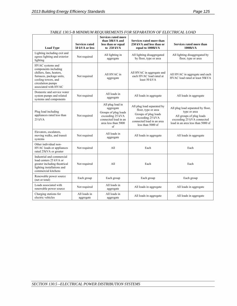
2013 Building Energy Efficiency Standards Page 125
SECTION 130.5 –ELECTRICAL POWER DISTRIBUTION SYSTEMS
TABLE 130.5-B MINIMUM REQUIREMENTS FOR SEPARATION OF ELECTRICAL LOAD
Load Type Services rated 50 kVA or less
Services rated more than 50kVA and less than or equal
to 250 kVA
Services rated more than 250 kVA and less than or
equal to 1000kVA Services rated more than
1000kVA
Lighting including exit and egress lighting and exterior lighting
Not required All lighting in aggregate
All lighting disaggregated by floor, type or area
All lighting disaggregated by floor, type or area
HVAC systems and components including chillers, fans, heaters, furnaces, package units, cooling towers, and circulation pumps associated with HVAC
Not required All HVAC in aggregate
All HVAC in aggregate and each HVAC load rated at
least 50 kVA
All HVAC in aggregate and each HVAC load rated at least 50kVA
Domestic and service water system pumps and related systems and components
Not required All loads in aggregate All loads in aggregate All loads in aggregate
Plug load including appliances rated less than 25 kVA
Not required
All plug load in aggregate
Groups of plug loads exceeding 25 kVA
connected load in an area less than 5000
sf
All plug load separated by floor, type or area
Groups of plug loads exceeding 25 kVA
connected load in an area less than 5000 sf
All plug load separated by floor, type or area
All groups of plug loads exceeding 25 kVA connected
load in an area less than 5000 sf
Elevators, escalators, moving walks, and transit systems
Not required All loads in aggregate All loads in aggregate All loads in aggregate
Other individual non-HVAC loads or appliances rated 25kVA or greater
Not required All Each Each
Industrial and commercial load centers 25 kVA or greater including theatrical lighting installations and commercial kitchens
Not required All Each Each
Renewable power source (net or total) Each group Each group Each group Each group
Loads associated with renewable power source Not required All loads in
aggregate All loads in aggregate All loads in aggregate
Charging stations for electric vehicles
All loads in aggregate
All loads in aggregate All loads in aggregate All loads in aggregate

Page 126 2013 2016 Building Energy Efficiency Standards
(This page left intentionally blank)

2013 2016 Building Energy Efficiency Standards Page 127
SECTION 140.0 – PERFORMANCE AND PRESCRIPTIVE COMPLIANCE APPROACHES
SUBCHAPTER 5 NONRESIDENTIAL, HIGH-RISE RESIDENTIAL, AND HOTEL/MOTEL OCCUPANCIES—PERFORMANCE AND PRESCRIPTIVE COMPLIANCE APPROACHES
FOR ACHIEVING ENERGY EFFICIENCY
SECTION 140.0 – PERFORMANCE AND PRESCRIPTIVE COMPLIANCE APPROACHES Nonresidential, high-rise residential and hotel/motel buildings shall meet all of the following:
(a) The requirements of Sections 100.0 through 110.10 applicable to the building project (mandatory measures).
(b) The requirements of Sections 120.0 through 130.5 (mandatory measures).
(c) Either the performance compliance approach (energy budgets) in Section 140.1 or the prescriptive compliance approach in Section 140.2 for the Climate Zone in which the building will be located. Climate zones are shown in FIGURE 100.1-A.
NOTE: The Commission periodically updates, publishes, and makes available to interested persons and local enforcement agencies precise descriptions of the Climate Zones, which is available by zip code boundaries depicted in the Reference Joint Appendices along with a list of the communities in each zone.
SECTION 140.1 – PERFORMANCE APPROACH: ENERGY BUDGETS A building complies with the performance approach if the energy budget calculated for the Proposed Design Building under Subsection (b) is no greater than the energy budget calculated for the Standard Design Building under Subsection (a).
(a) Energy Budget for the Standard Design Building. The energy budget for a proposed building is determined by applying the mandatory and prescriptive requirements to the Proposed Design Building. The energy budget is the sum of the TDV energy for space-conditioning, indoor lighting, mechanical ventilation, service water heating, and covered process loads.
(b) Energy Budget for the Proposed Design Building. The energy budget for a Proposed Design Building is determined by calculating the TDV energy for the Proposed Design Building. The energy budget is the sum of the TDV energy for space-conditioning, indoor lighting, mechanical ventilation and service water heating and covered process loads.
(c) Calculation of Energy Budget. The TDV energy for both the Standard Design Building and the Proposed Design Building shall be computed by Compliance Software certified for this use by the Commission. The processes for Compliance Software approval by the Commission are documented in the Nonresidential ACM Approval Manual.

Page 128 2013 2016 Building Energy Efficiency Standards
SECTION 140.2 – PRESCRIPTIVE APPROACH
SECTION 140.2 – PRESCRIPTIVE APPROACH In order to comply with the prescriptive approach under this section, a building shall be designed with and shall have constructed and installed:
(a) A building envelope that complies with Section 140.3(a) or 140.3(b), and for applicable buildings Section 140.3(c);
(b) A space-conditioning system that complies with Section 140.4;
(c) A service water-heating system that complies with Section 140.5;
(d) A lighting system that complies with Section 140.6;
(e) An outdoor lighting system that complies with Section 140.7;
(f) Interior and exterior signs that comply with Section 140.8; and
(g) Covered processes that comply with Section 140.9.

2013 Building Energy Efficiency Standards Page 129
SECTION 140.3 – PRESCRIPTIVE REQUIREMENTS FOR BUILDING ENVELOPES
SECTION 140.3 – PRESCRIPTIVE REQUIREMENTS FOR BUILDING ENVELOPES A building complies with this section by being designed with and having constructed and installed either: (1) envelope components that comply with each of the requirements in Subsection (a) for each individual component and the requirements of Subsection (c) where they apply; or (2) an envelope that complies with the overall requirements in Subsection (b) and the requirements of Subsection (c) where they apply.
(a) Envelope Component Approach.
1. Exterior roofs and ceilings. Exterior roofs and ceilings shall comply with each of the applicable requirements in this subsection:
A. Roofing Products. Shall meet the requirements of Section 110.8 and the applicable requirements of Subsections i through ii:
i. Nonresidential buildings:
a. Low-sloped roofs in Climate Zones 1 through 16 shall have:
1. A minimum aged solar reflectance of 0.63 and a minimum thermal emittance of 0.75; or
2. A minimum Solar Reflectance Index (SRI) of 75.
EXCEPTION 1 to Section 140.3(a)1Aia: Wood-framed roofs in Climate Zones 3 and 5 are exempt from the requirements of Section 140.3(a)1Aia if the roof assembly has a U-factor of 0.0390.034 or lower.
EXCEPTION 2 to Section 140.3(a)1Aia: Metal building roofs in Climate Zones 3 and 5 are exempt from the requirements if the roof assembly has a U-factor of 0.048 or lower.
EXCEPTION 3 2 to Section 140.3(a)1Aia: Roof constructions that have thermal mass with a weight of at least 25 lb/ft² over the roof membrane are exempt from the requirements of Section 140.3(a)1Aia.
EXCEPTION 4 323 to SECTION 140.3(a)1Aia: An aged solar reflectance less than 0.63 is allowed provided the maximum roof/ceiling U-factor in TABLE 140.3 is not exceeded.
b. Steep-sloped roofs in Climate Zones 1 through 16 shall have a minimum aged solar reflectance of 0.20 and a minimum thermal emittance of 0.75, or a minimum SRI of 16.
ii. High-rise residential buildings and hotels and motels:
a. Low-sloped roofs in Climate Zones 9, 10, 11, 13, 14 and 15 shall have a minimum aged solar reflectance of 0.55 and a minimum thermal emittance of 0.75, or a minimum SRI of 64.
EXCEPTION to Section 140.3(a)1Aiia: Roof constructions that have thermal mass with a weight of at least 25 lb/ft² over the roof membrane .
b. Steep-sloped roofs in Climate Zones 2 through 15 shall have a minimum aged solar reflectance of 0.20 and a minimum thermal emittance of 0.75, or a minimum SRI of 16.

Page 130 2013 2016 Building Energy Efficiency Standards
SECTION 140.3 – PRESCRIPTIVE REQUIREMENTS FOR BUILDING ENVELOPES
TABLE 140.3 ROOF/CEILING INSULATION TRADEOFF FOR AGED SOLAR REFLECTANCE
Nonresidential
Aged Solar Reflectance
Metal Building
Climate Zone
1-16
U-factor
Wood framed and Other
Climate Zone
1 &56 & 7
U-factor
Wood Framed and Other
All Other Climate Zones Zone
2-4, 9-16
U-factor
0.62-0.6056 0.0410.061 0.0490.045 0.0340.036
0.59-0.55-0.46 0.0380.054 0.0450.041 0.0320.034
0.54-0.500.45-0.36 0.0360.049 0.0430.038 0.0310.032
0.49-0.450.35-0.25 0.0350.047 0.0420.035 0.0280.030
0.44-0.40 0.043 0.033 0.028
0.39-0.35 0.039 0.031 0.027
0.34-0.30 0.035 0.029 0.025
0.29-0.25 0.033 0.027 0.024
EXCEPTION to Section 140.3(a)1A: Roof area covered by building integrated photovoltaic panels and building integrated solar thermal panels are not required to meet the minimum requirements for solar reflectance, thermal emittance, or SRI.
B. Roof Insulation. Roofs shall have an overall assembly U-factor no greater than the applicable value in Table 140.3- B, C or D, and where required by Section 110.8(e), insulation shall be placed in direct contact with a continuous roof or drywall ceiling.
2. Exterior Walls. Exterior walls shall have an overall assembly U-factor no greater than the applicable value in TABLE 140.3-B, C or D.
3. Demising Walls. Demising walls shall meet the requirements of Section 110.8(f).
4. Exterior Floors and Soffits. Exterior floors and soffits shall have an overall assembly U-factor no greater than the applicable value in TABLE 140.3-B, C or D.
5. Fenestration. Vertical Windows shall:
A. have (1) a west-facing area no greater than 40 percent of the gross west-facing exterior wall area, or 6 feet times the west-facing display perimeter, whichever is greater; and (2) a total area no greater than 40 percent of the gross exterior wall area, or 6 feet times the display perimeter, whichever is greater; and
EXCEPTION to Section 140.3(a)5A: Window area in demising walls is not counted as part of the window area for this requirement. Demising wall area is not counted as part of the gross exterior wall area or display perimeter for this requirement.
B. Have an area-weighted average U-factor no greater than the applicable value in TABLE140.3 -B, C or D.
EXCEPTION to Section 140.3(a)5B: For vertical fenestration containing chromogenic type glazing:

2013 Building Energy Efficiency Standards Page 131
SECTION 140.3 – PRESCRIPTIVE REQUIREMENTS FOR BUILDING ENVELOPES
i. the lower-rated labeled U-factor shall be used with automatic controls to modulate the amount of heat flow into the space in multiple steps in response to daylight levels or solar intensity; and
ii. chromogenic glazing shall be considered separately from other fenestration; and
iii. area-weighted averaging with other fenestration that is not chromogenic shall not be permitted.
C. Have an area-weighted average Relative Solar Heat Gain Coefficient, RSHGC, excluding the effects of interior shading, no greater than the applicable value in TABLE 140.3-B, C or D.
For purposes of this paragraph, the Relative Solar Heat Gain Coefficient, RSHGC, of a vertical window is:
i. the solar heat gain coefficient of the window; or
ii. relative solar heat gain as calculated by EQUATION 140.3-A, if the window has an overhang that extends beyond each side of the window jamb by a distance equal to the overhang’s horizontal projection.
EXCEPTION 1 to Section 140.3(a)5C: An area-weighted average Relative Solar Heat Gain of 0.56 or less shall be used for windows:
a. that are in the first story of exterior walls that form a display perimeter; and b. for which codes restrict the use of overhangs to shade the windows.
EXCEPTION 2 to Section 140.3(a)5C: For vertical fenestration containing chromogenic type glazing:
i. the lower-rated labeled RSHGC shall be used with automatic controls to modulate the amount of
heat flow into the space in multiple steps in response to daylight levels or solar intensity; and
ii. chromogenic glazing shall be considered separately from other fenestration; and
iii. area-weighted averaging with other fenestration that is not chromogenic shall not be permitted.
D. Have an area-weighted average Visible Transmittance (VT) no less than the applicable value in TABLE 140.3-B and C, or EQUATION 140.3-B, as applicable.
EXCEPTION 1 to Section 140.3(a)5D: When the fenestration’s primary and secondary sidelit daylit zones are completely overlapped by one or more skylit daylit zones, then the fenestration need not comply with Section 140.3(a)5D.
EXCEPTION 2 to Section 140.3(a)5D: If the fenestration’s visible transmittance is not within the scope of NFRC 200, ASTM E972, or EQUATION 140.3-B, then the VT shall be calculated according to Reference Nonresidential Appendix NA6.
EXCEPTION 3 to Section 140.3(a)5D: For vertical fenestration containing chromogenic type glazing:
i. the higher rated labeled VT shall be used with automatic controls to modulate the amount of light transmitted into the space in multiple steps in response to daylight levels or solar intensity; and
ii. chromogenic glazing shall be considered separately from other fenestration; and
iii. area-weighted averaging with other fenestration that is not chromogenic shall not be permitted.

Page 132 2013 2016 Building Energy Efficiency Standards
SECTION 140.3 – PRESCRIPTIVE REQUIREMENTS FOR BUILDING ENVELOPES
EQUATION 140.3-A RELATIVE SOLAR HEAT GAIN COEFFICIENT, RSHGC
⎥⎥⎦
⎤
⎢⎢⎣
⎡⎟⎠⎞
⎜⎝⎛++×=
2
VHb
VaH1SHGCRSHG win
WHERE:
RSHG = Relative solar heat gain.
SHGCwin = Solar heat gain coefficient of the window.
H = Horizontal projection of the overhang from the surface of the window in feet, but no greater than V.
V = Vertical distance from the window sill to the bottom of the overhang in feet.
a = -0.41 for north-facing windows, -1.22 for south-facing windows, and -0.92 for east and west-facing windows.
b = 0.20 for north-facing windows, 0.66 for south-facing windows, and 0.35 for east and west-facing windows.
EQUATION 140.3-B VERTICAL FENESTRATION MINIMUM VT
VT ≥ 0.11/ WWR
WHERE:
WWR = Window Wall Ratio, the ratio of (i) the total window area of the entire building to (ii) the total gross exterior wall area of the entire building. If the WWR is greater than 0.40, then 0.40 shall be used as the value for WWR in EQUATION 140.3-B.
VT = Visible Transmittance of framed window.
6. Skylights. Skylights shall:
A. Have an area no greater than 5 percent of the gross exterior roof area (SRR); and
EXCEPTION to Section 140.3(a)6A: Atria over 55 feet high shall have a skylight area no greater than 10 percent of the gross exterior roof area.
B. Have an Area-Weighted Performance Rating U-factor no greater than the applicable value in TABLE 140.3-B, C or D.
EXCEPTION to Section 140.3(a)6B: For skylights containing chromogenic type glazing:
i. the lower-rate labeled U-factor shall be used with automatic controls to modulate the amount of U-factor heat flow into the space in multiple steps in response to daylight levels or solar intensity; and
ii. chromogenic glazing shall be considered separately from other skylights; and
iii. area-weighted averaging with other skylights that is not chromogenic shall not be permitted.
C. Have an area-weighted performance rating Solar Heat Gain Coefficient no greater than the applicable value in TABLE 140.3-B, C or D.
EXCEPTION to Section 140.3(a)6C: For skylights containing chromogenic type glazing:
i. the lower-rated labeled SHGC shall be used with automatic controls to modulate the amount of heat flow into the space in multiple steps in response to daylight levels or solar intensity; and
ii. chromogenic glazing shall be considered separately from other skylights; and
iii. area-weighted averaging with other skylights that are not chromogenic shall not be permitted.
2013 Building Energy Efficiency Standards Page 133
SECTION 140.3 – PRESCRIPTIVE REQUIREMENTS FOR BUILDING ENVELOPES
D. Have an Area-Weighted Performance Rating VT no less than the applicable value in TABLE 140.3-B or C; and
EXCEPTION to Section 140.3(a)6D: For skylights containing chromogenic type glazing:
i. the higher-rated labeled VT shall be used with automatic controls to modulate the amount of light transmitted into the space in multiple steps in response to daylight levels or solar intensity and;
ii. chromogenic glazing shall be considered separately from other skylights; and
iii. area-weighted averaging with other skylights that are not chromogenic shall not be permitted.
E. Have a glazing material or diffuser that has a measured haze value greater than 90 percent, determined according to ASTM D1003, or other test method approved by the Energy Commission.
7. Exterior doors. All exterior doors that separate conditioned space from unconditioned space or from ambient air shall have a U-factor not greater than the applicable value in TABLE 140.3-B, C or D. Doors that are more than one-half glass in area are considered Glazed Doors.
8. Relocatable Public School Buildings. In complying with Sections 140.3(a)1 to 7 shall meet the following:
A. Relocatable public school buildings shall comply with TABLE 140.3-B for a specific Climate Zone when the manufacturer or builder of the relocatable public school building certifies that the building is intended for use only in a specific Climate Zone; or
B. Relocatable public school buildings shall comply with TABLE 140.3-D for any Climate Zone when the manufacturer or builder of the relocatable public school building certifies that the building is intended for use in any Climate Zone; and
C. The manufacturer or builder of a relocatable public school building shall certify that components of the building comply with requirements of this section by:
i. The placement of two (2) metal identification labels on the building, one mechanically fastened and visible from the exterior and the other mechanically fastened to the interior frame above the ceiling at the end of the module., both labels stating (in addition to any other information by the Division of the State Architect or other law) "Complies with Title 24, Part 6 for all Climate Zones; and
ii. Identification of the location of the 2 labels on the plans submitted to the enforcing agency.
9. Air Barrier. To meet the requirement of TABLE 140.3-B, all buildings shall have a continuous air barrier that is designed and constructed to control air leakage into, and out of, the building’s conditioned space. The air barrier shall be sealed at all joints for its entire length and shall be composed of:
A. Materials that have an air permeance not exceeding 0.004 cfm/ft2, under a pressure differential of 0.3 in. w.g. (1.57 psf) (0.02 L/m2 at 75 pa), when tested in accordance with ASTM E2178; or
EXCEPTION to Section 140.3(a)9A: Materials in TABLE 140.3-A shall be deemed to comply with Section 140.3(a)9A provided if all joints are sealed and all of the materials are installed as air barriers in accordance with the manufacturer's instructions.

Page 134 2013 2016 Building Energy Efficiency Standards
SECTION 140.3 – PRESCRIPTIVE REQUIREMENTS FOR BUILDING ENVELOPES
TABLE 140.3-A MATERIALS DEEMED TO COMPLY WITH SECTION 140.3(a)9A
MATERIALS AND THICKNESS MATERIALS AND THICKNESS
1 Plywood – min. 3/8 inches thickness 9 Built up roofing membrane
2 Oriented strand board – min. 3/8 inches thickness 10 Modified bituminous roof membrane
3 Extruded polystyrene insulation board – min. ½ inches thickness 11 Fully adhered single-ply roof membrane
4 Foil-back polyisocyanurate insulation board – min. ½ inches thickness 12
A Portland cement or Portland sand parge, or a gypsum plaster, each with min. 5/8 inches
thickness
5 Closed cell spray foam with a minimum density of 2.0 pcf and a min. 2.0 inches
thickness 13 Cast-in-place concrete, or precast concrete
6 Open cell spray foam with a density no less
than 0.4 pcf and no greater than 1.5 pcf, and a min. 5½ inches thickness
14 Fully grouted concrete block masonry
7 Exterior or interior gypsum board min. 1/2 inches thickness 15 Sheet steel or sheet aluminum
8 Cement board – min. 1/2 inches thickness --- ---------------------------------
B. Assemblies of materials and components that have an average air leakage not exceeding 0.04 cfm/ft2, under a pressure differential of 0.3 in. w.g (1.57 psf) (0.2 L/m2 at 75 pa), when tested in accordance with ASTM E2357, ASTM E1677, ASTM E1680, or ASTM E283; or
EXCEPTION to Section 140.3(a)9B: The following materials shall be deemed to comply with Section 140.3(a)9B if all joints are sealed and all of the materials are installed as air barriers in accordance with the manufacturer's instructions:
i. Concrete masonry walls that have at least two coatings of paint or at least two coatings of sealer coating.
ii. Concrete masonry walls with integral rigid board insulation.
iii. Structurally Insulated Panels.
iv. Portland cement or Portland sand parge, or stucco, or a gypsum plaster, each with min. 1/2 inches thickness
C. The entire building has an air leakage rate not exceeding 0.40 cfm/ft2 at a pressure differential of 0.3 in w.g. (1.57 psf) (2.0 L/ m2 at 75 pa), when the entire building is tested, after completion of construction, in accordance with ASTM E779 or another test method approved by the Commission.
EXCEPTION to Section 140.3(a)9: Relocatable Public School Buildings.

2013 Building Energy Efficiency Standards Page 135
SECTION 140.3 – PRESCRIPTIVE REQUIREMENTS FOR BUILDING ENVELOPES
TABLE 140.3-B – PRESCRIPTIVE ENVELOPE CRITERIA FOR NONRESIDENTIAL BUILDINGS (INCLUDING RELOCATABLE PUBLIC SCHOOL BUILDINGS WHERE MANUFACTURER CERTIFIES USE ONLY IN SPECIFIC CLIMATE ZONE; NOT INCLUDING HIGH-RISE RESIDENTIAL BUILDINGS
AND GUEST ROOMS OF HOTEL/MOTEL BUILDINGS)
Climate Zone
1 2 3 4 5 6 7 8 9 10 11 12 13 14 15 16
Env
elop
e
Max
imum
U-f
acto
r
Roo
fs/
Cei
lings
Metal Building 0.041 0.041 0.041 0.041 0.041 0.041 0.041 0.041 0.041 0.041 0.041 0.041 0.041 0.041 0.041 0.041
Wood Framed and Other 0.034 0.034 0.034 0.034 0.034 0.049 0.049 0.067 0.034 0.034 0.034 0.034 0.034 0.034 0.034 0.034
Wal
ls
Metal Building 0.113 0.061 0.113 0.061 0.061 0.113 0.113 0.061 0.061 0.061 0.061 0.061 0.061 0.061 0.057 0.061
Metal-framed 0.069 0.062 0.082 0.062 0.062 0.069 0.069 0.062 0.062 0.062 0.062 0.062 0.062 0.062 0.062 0.062
Mass Light1 0.196 0.170 0.278 0.227 0.440 0.440 0.440 0.440 0.440 0.170 0.170 0.170 0.170 0.170 0.170 0.170
Mass Heavy1 0.253 0.650 0.650 0.650 0.650 0.690 0.690 0.690 0.690 0.650 0.184 0.253 0.211 0.184 0.184 0.160
Wood-framed and Other 0.095 0.059 0.110 0.059 0.102 0.110 0.110 0.102 0.059 0.059 0.045 0.059 0.059 0.059 0.042 0.059
Floo
rs/
Soff
its
Mass 0.092 0.092 0.269 0.269 0.269 0.269 0.269 0.269 0.269 0.269 0.092 0.092 0.092 0.092 0.092 0.058
Other 0.048 0.039 0.071 0.071 0.071 0.071 0.071 0.071 0.071 0.071 0.039 0.071 0.071 0.039 0.039 0.039
Roo
fing
Prod
ucts
Low
-sl
oped
Aged Solar Reflectance 0.63 0.63 0.63 0.63 0.63 0.63 0.63 0.63 0.63 0.63 0.63 0.63 0.63 0.63 0.63 0.63
Thermal Emittance 0.75 0.75 0.75 0.75 0.75 0.75 0.75 0.75 0.75 0.75 0.75 0.75 0.75 0.75 0.75 0.75
Stee
p-
Slop
ed Aged Solar Reflectance 0.20 0.20 0.20 0.20 0.20 0.20 0.20 0.20 0.20 0.20 0.20 0.20 0.20 0.20 0.20 0.20
Thermal Emittance 0.75 0.75 0.75 0.75 0.75 0.75 0.75 0.75 0.75 0. 75 0.75 0.75 0.75 0.75 0.75 0.75
Air Barrier NR NR NR NR NR NR NR NR NR REQ REQ REQ REQ REQ REQ REQ
Exterior Doors, Maximum U-factor
Non-Swinging 0.50 1.45 1.45 1.45 1.45 1.45 1.45 1.45 1.45 1.45 1.45 1.45 1.45 1.45 1.45 0.50
Swinging 0.70 0.70 0.70 0.70 0.70 0.70 0.70 0.70 0.70 0.70 0.70 0.70 0.70 0.70 0.70 0.70
Climate Zone
1 2 3 4 5 6 7 8 9 10 11 12 13 14 15 16
Env
elop
e
Max
imum
U-
fact
or Roo
fs/
Cei
lings
Metal Building 0.065 0.065 0.065 0.065 0.065 0.065 0.065 0.065 0.065 0.065 0.065 0.065 0.065 0.065 0.065 0.065
Wood Framed and Other 0.049 0.039 0.039 0.039 0.049 0.075 0.067 0.067 0.039 0.039 0.039 0.039 0.039 0.039 0.039 0.039
Wal
ls Metal Building 0.113 0.061 0.113 0.061 0.061 0.113 0.113 0.061 0.061 0.061 0.061 0.061 0.061 0.061 0.057 0.061
Metal-framed 0.098 0.062 0.082 0.062 0.062 0.098 0.098 0.062 0.062 0.062 0.062 0.062 0.062 0.062 0.062 0.062

Page 136 2013 2016 Building Energy Efficiency Standards
SECTION 140.3 – PRESCRIPTIVE REQUIREMENTS FOR BUILDING ENVELOPES
Mass Light1 0.196 0.170 0.278 0.227 0.440 0.440 0.440 0.440 0.440 0.170 0.170 0.170 0.170 0.170 0.170 0.170
Mass Heavy1 0.253 0.650 0.650 0.650 0.650 0.690 0.690 0.690 0.690 0.650 0.184 0.253 0.211 0.184 0.184 0.160
Wood-framed and Other 0.102 0.059 0.110 0.059 0.102 0.110 0.110 0.102 0.059 0.059 0.059 0.059 0.059 0.059 0.042 0.059
Floo
rs/
Soff
its
Mass 0.092 0.092 0.269 0.269 0.269 0.269 0.269 0.269 0.269 0.269 0.092 0.092 0.092 0.092 0.092 0.058
Other 0.048 0.039 0.071 0.071 0.071 0.071 0.071 0.071 0.071 0.071 0.039 0.071 0.071 0.039 0.039 0.039
Roo
fing
Prod
ucts
Low
-sl
oped
Aged Solar Reflectance 0.63 0.63 0.63 0.63 0.63 0.63 0.63 0.63 0.63 0.63 0.63 0.63 0.63 0.63 0.63 0.63
Thermal Emittance 0.75 0.75 0.75 0.75 0.75 0.75 0.75 0.75 0.75 0.75 0.75 0.75 0.75 0.75 0.75 0.75
Stee
p-
Slop
ed Aged Solar Reflectance 0.20 0.20 0.20 0.20 0.20 0.20 0.20 0.20 0.20 0.20 0.20 0.20 0.20 0.20 0.20 0.20
Thermal Emittance 0.75 0.75 0.75 0.75 0.75 0.75 0.75 0.75 0.75 0. 75 0.75 0.75 0.75 0.75 0.75 0.75
Air Barrier NR NR NR NR NR NR NR NR NR REQ REQ REQ REQ REQ REQ REQ
Exterior Doors, Maximum U-factor
Non-Swinging 0.50 1.45 1.45 1.45 1.45 1.45 1.45 1.45 1.45 1.45 1.45 1.45 1.45 1.45 1.45 0.50
Swinging 0.70 0.70 0.70 0.70 0.70 0.70 0.70 0.70 0.70 0.70 0.70 0.70 0.70 0.70 0.70 0.70

2013 Building Energy Efficiency Standards Page 137
SECTION 140.3 – PRESCRIPTIVE REQUIREMENTS FOR BUILDING ENVELOPES
CONTINUED: TABLE 140.3-B – PRESCRIPTIVE ENVELOPE CRITERIA FOR NONRESIDENTIAL BUILDINGS (INCLUDING RELOCATABLE PUBLIC SCHOOL BUILDINGS WHERE MANUFACTURER CERTIFIES USE ONLY IN SPECIFIC CLIMATE ZONE; NOT INCLUDING HIGH-RISE RESIDENTIAL
BUILDINGS AND GUEST ROOMS OF HOTEL/MOTEL BUILDINGS)
Env
elop
e
Fene
stra
tion
All Climate Zones
Fixed Window
Operable Window
Curtainwall or Storefront Glazed Doors
Ver
tical
Area-Weighted Performance Rating
Max U-factor
0.36 0.46 0.41 0.45
Max RSHGC
0.25 0.22 0.26 0.23
Area-Weighted Performance Rating Min VT 0.42 0.32 0.46 0.17
Maximum WWR% 40%
Skyl
ight
s
Glass, Curb Mounted Glass, Deck Mounted Plastic, Curb Mounted
Area-Weighted Performance Rating
Max U-factor
0.58 0.46 0.88
Max SHGC 0.25 0.25 NR
Area-Weighted Performance Rating Min VT 0.49 0.49 0.64
Maximum SRR% 5%

Page 138 2013 2016 Building Energy Efficiency Standards
SECTION 140.3 – PRESCRIPTIVE REQUIREMENTS FOR BUILDING ENVELOPES
TABLE 140.3-C – PRESCRIPTIVE ENVELOPE CRITERIA FOR HIGH-RISE RESIDENTIAL BUILDINGS AND GUEST ROOMS OF HOTEL/MOTEL BUILDINGS
Climate Zone 1 2 3 4 5 6 7 8 9 10 11 12 13 14 15 16
Env
elop
e
Max
imum
U-f
acto
r Roo
fs/
Cei
lings
Metal Building 0.041 0.041 0.041 0.041 0.041 0.041 0.041 0.041 0.041 0.041 0.041 0.041 0.041 0.041 0.041 0.041
Wood Framed and Other 0.028 0.028 0.034 0.028 0.034 0.034 0.039 0.028 0.028 0.028 0.028 0.028 0.028 0.028 0.028 0.028
Wal
ls
Metal Building 0.061 0.061 0.061 0.061 0.061 0.061 0.061 0.061 0.061 0.061 0.057 0.057 0.057 0.057 0.057 0.057
Metal-framed 0.069 0.069 0.069 0.069 0.069 0.069 0.105 0.069 0.069 0.069 0.069 0.069 0.069 0.069 0.048 0.069
Mass Light1 0.170 0.170 0.170 0.170 0.170 0.227 0.227 0.227 0.196 0.170 0.170 0.170 0.170 0.170 0.170 0.170
Mass Heavy1 0.160 0.160 0.160 0.184 0.211 0.690 0.690 0.690 0.690 0.690 0.184 0.253 0.211 0.184 0.184 0.160
Wood-framed and Other 0.059 0.059 0.059 0.059 0.059 0.059 0.059 0.059 0.059 0.059 0.042 0.059 0.059 0.042 0.042 0.042
Floo
rs/
Soff
its
Mass 0.045 0.045 0.058 0.058 0.058 0.069 0.092 0.092 0.092 0.069 0.058 0.058 0.058 0.045 0.058 0.037
Other 0.034 0.034 0.039 0.039 0.039 0.039 0.071 0.039 0.039 0.039 0.039 0.039 0.039 0.034 0.039 0.034
Roo
fing
Prod
ucts
Low
-slo
ped Aged Solar
Reflectance NR NR NR NR NR NR NR NR 0.55 0.55 0.55 NR 0.55 0.55 0.55 NR
Thermal Emittance NR NR NR NR NR NR NR NR 0.75 0.75 0.75 NR 0.75 0.75 0.75 NR
St
eep-
Sl
oped
Aged Solar Reflectance NR 0.20 0.20 0.20 0.20 0.20 0.20 0.20 0.20 0.20 0.20 0.20 0.20 0.20 0.20 NR
Thermal Emittance NR 0.75 0.75 0.75 0.75 0.75 0.75 0.75 0.75 0. 75 0.75 0.75 0.75 0.75 0.75 NR
Exterior Doors, Maximum U-
factor
Non-Swinging 0.50 1.45 1.45 1.45 1.45 1.45 1.45 1.45 1.45 1.45 1.45 1.45 1.45 1.45 1.45 0.50
Swinging 0.70 0.70 0.70 0.70 0.70 0.70 0.70 0.70 0.70 0.70 0.70 0.70 0.70 0.70 0.70 0.70
Climate Zone
1 2 3 4 5 6 7 8 9 10 11 12 13 14 15 16
Env
elop
e
Max
imum
U
-fac
tor
Roo
fs/
Cei
lings
Metal Building 0.065 0.065 0.065 0.065 0.065 0.065 0.065 0.065 0.065 0.065 0.065 0.065 0.065 0.065 0.065 0.065
Wood Framed and Other 0.034 0.028 0.039 0.028 0.039 0.039 0.039 0.028 0.028 0.028 0.028 0.028 0.028 0.028 0.028 0.028

2013 Building Energy Efficiency Standards Page 139
SECTION 140.3 – PRESCRIPTIVE REQUIREMENTS FOR BUILDING ENVELOPES
Wal
ls
Metal Building 0.061 0.061 0.061 0.061 0.061 0.061 0.061 0.061 0.061 0.061 0.057 0.057 0.057 0.057 0.057 0.057
Metal-framed 0.105 0.105 0.105 0.105 0.105 0.105 0.105 0.105 0.105 0.105 0.105 0.105 0.105 0.105 0.105 0.105
Mass Light1 0.170 0.170 0.170 0.170 0.170 0.227 0.227 0.227 0.196 0.170 0.170 0.170 0.170 0.170 0.170 0.170
Mass Heavy1 0.160 0.160 0.160 0.184 0.211 0.690 0.690 0.690 0.690 0.690 0.184 0.253 0.211 0.184 0.184 0.160
Wood-framed and Other 0.059 0.059 0.059 0.059 0.059 0.059 0.059 0.059 0.059 0.059 0.042 0.059 0.059 0.042 0.042 0.042
Floo
rs/
Soff
its
Mass 0.045 0.045 0.058 0.058 0.058 0.069 0.092 0.092 0.092 0.069 0.058 0.058 0.058 0.045 0.058 0.037
Other 0.034 0.034 0.039 0.039 0.039 0.039 0.071 0.039 0.039 0.039 0.039 0.039 0.039 0.034 0.039 0.034
Roo
fing
Prod
ucts
Low
-slo
ped Aged Solar
Reflectance NR NR NR NR NR NR NR NR 0.55 0.55 0.55 NR 0.55 0.55 0.55 NR
Thermal Emittance NR NR NR NR NR NR NR NR 0.75 0.75 0.75 NR 0.75 0.75 0.75 NR
St
eep-
Sl
oped
Aged Solar Reflectance NR 0.20 0.20 0.20 0.20 0.20 0.20 0.20 0.20 0.20 0.20 0.20 0.20 0.20 0.20 NR
Thermal Emittance NR 0.75 0.75 0.75 0.75 0.75 0.75 0.75 0.75 0. 75 0.75 0.75 0.75 0.75 0.75 NR
Exterior Doors, Maximum U-
factor
Non-Swinging 0.50 1.45 1.45 1.45 1.45 1.45 1.45 1.45 1.45 1.45 1.45 1.45 1.45 1.45 1.45 0.50
Swinging 0.70 0.70 0.70 0.70 0.70 0.70 0.70 0.70 0.70 0.70 0.70 0.70 0.70 0.70 0.70 0.70

Page 140 2013 2016 Building Energy Efficiency Standards
SECTION 140.3 – PRESCRIPTIVE REQUIREMENTS FOR BUILDING ENVELOPES
CONTINUED: TABLE 140.3-C – PRESCRIPTIVE ENVELOPE CRITERIA FOR HIGH-RISE RESIDENTIAL BUILDINGS AND GUEST ROOMS OF HOTEL/MOTEL BUILDINGS
Env
elop
e
Fene
stra
tion
All Climate Zones
Fixed Window
Operable Window
Curtainwall/ Storefront
Glazed Doors
Ver
tical
Area-Weighted Performance Rating
Max U-factor
0.36 0.46 0.41 0.45
Max RSHGC 0.25 0.22 0.26 0.23
Area-Weighted Performance Rating Min VT 0.42 0.32 0.46 0.17
Maximum WWR% 40%
Skyl
ight
s
Glass, Curb Mounted Glass, Deck Mounted Plastic, Curb Mounted
Area-Weighted Performance Rating
Max U-factor
0.58 0.46 0.88
Max SHGC 0.25 0.25 NR
Area-Weighted Performance Rating Min VT 0.49 0.49 0.64
Maximum SRR% 5%
Notes:
1. Light mass walls are walls with a heat capacity of at least 7.0 Btu/ft²-oF and less than 15.0 Btu/ft²-oF. Heavy mass walls are walls with a heat capacity of at least 15.0 Btu/ft²-oF.

2013 Building Energy Efficiency Standards Page 141
SECTION 140.3 – PRESCRIPTIVE REQUIREMENTS FOR BUILDING ENVELOPES
TABLE 140.3-D PRESCRIPTIVE ENVELOPE CRITERIA FOR RELOCATABLE PUBLIC SCHOOL BUILDINGS FOR USE IN ALL CLIMATE ZONES
Roofs/ Ceilings Metal Buildings
Maximum U-factor
0.048 Non-Metal Buildings 0.039
Walls
Wood frame buildings 0.059 Metal frame buildings 0.062
Metal buildings 0.057 Mass/7.0≤ HC 0.170
All Other Walls 0.059 Floors and Soffits Floors and Soffits 0.048
Roofing Products
Low-Sloped Aged Solar Reflectance 0.63
Thermal Emittance 0.75
Steep-Sloped Aged Solar Reflectance 0.20
Thermal Emittance 0.75
Fenestration
Windows Maximum U-factor 0.47
Maximum SHGC 0.26
Glazed Doors Maximum U-factor 0.45
Maximum SHGC 0.23
Skylights
Glass with Curb
Maximum U-factor
0.99
Glass without Curb 0.57
Plastic with Curb 0.87
Glass Type 0-2% SRR
Maximum SHGC
0.46
2.1-5% SRR 0.36
Plastic Type
0-2% SRR 0.69
2.1-5% SRR 0.57
Exterior Doors Non-Swinging doors
Maximum U-factor 0.50
Swinging doors 0.70
Roofs/Ceilings
Roofs of Metal Buildings Maximum U-factor 0.048
Roofs of all non-Metal Buildings Maximum U-factor 0.039
Roofing Products – Aged Solar Reflectance/Emittance
Low-sloped Low-Sloped 0.63/0.75
Steep-Sloped Steep-Sloped 0.20/0.75
Walls

Page 142 2013 2016 Building Energy Efficiency Standards
SECTION 140.3 – PRESCRIPTIVE REQUIREMENTS FOR BUILDING ENVELOPES
Walls of Wood frame buildings Maximum U-factor 0.059
Walls of Metal frame buildings Maximum U-factor 0.062
Walls of Metal buildings Maximum U-factor 0.057
Walls of Mass/7.0≤ HC, any building Maximum U-factor 0.170
All Other Walls Maximum U-factor 0.059
Floors and soffits of all buildings Maximum U-factor 0.048
Windows of all buildings
U-factor Maximum U-factor 0.47
RSHGC Maximum RSHGC 0.26
Glazed Doors, All Buildings
Max Average Weighted U-factor 0.45
Max Average Weighted RSHGC 0.23
Exterior Doors, all buildings
Non-Swinging doors Maximum U-factor 0.50
Swinging doors Maximum U-factor 0.70
Skylights
Glass with Curb Maximum U-factor 0.99
Glass without Curb Maximum U-factor 0.57
Plastic with Curb Maximum U-factor 0.87
Glass Skylights 0-2% SRR Maximum SHGC 0.46
2.1-5% SRR Maximum SHGC 0.36
Plastic Skylights 0-2% SRR Maximum SHGC 0.69
2.1-5% SRR Maximum SHGC 0.57

2013 Building Energy Efficiency Standards Page 143
SECTION 140.3 – PRESCRIPTIVE REQUIREMENTS FOR BUILDING ENVELOPES
(b) RESERVED
(c) Minimum Daylighting Requirement for Large Enclosed Spaces. In Climate Zones 2 through 15, conditioned enclosed spaces, and unconditioned enclosed spaces, that are greater than 5,000 ft² and that are directly under a roof with ceiling heights greater than 15 feet, shall meet the following requirements:
1. A combined total of at least 75percent of the floor area, as determined in building floor plan (drawings) view, shall be within one or more of the following:
A. Primary Sidelight Daylight Zone in accordance with Section 130.1(d)1B, or
B. Skylit Daylit Zone in accordance with Section 130.1(d)1A.
2. All Skylit Daylit Zones and Primary Sidelit Daylit Zones shall be shown on building plans.
3. General lighting in daylit zones shall be controlled in accordance with Section 130.1(d).
4. Skylights shall:
A. Have a glazing material or diffuser that has a measured haze value greater than 90 percent, tested according to ASTM D1003 (notwithstanding its scope) or another test method approved by the Commission; and
B. If the space is conditioned, meet the requirements in Section 140.3(a)6.
EXCEPTION 1 to Section 140.3(c): Auditoriums, churches, movie theaters, museums, and refrigerated warehouses.
EXCEPTION 2 to Section 140.3(c): In buildings with unfinished interiors, future enclosed spaces for which there are plans to have:
A. A floor area of less than or equal to 5,000 square feet; or
B. Ceiling heights of less than or equal to 15 feet. This exception shall not be used for S-1 or S-2 (storage), or for F-1 or F-2 (factory) occupancies.
EXCEPTION 3 to Section 140.3(c): Enclosed spaces having a designed general lighting system with a lighting power density less than 0.5 watts per square foot.

Page 144 2013 2016 Building Energy Efficiency Standards
SECTION 140.4 – PRESCRIPTIVE REQUIREMENTS FOR SPACE CONDITIONING SYSTEMS
SECTION 140.4 – PRESCRIPTIVE REQUIREMENTS FOR SPACE CONDITIONING SYSTEMS A building complies with this section by being designed with and having constructed and installed a space-conditioning system that meets the applicable requirements of Subsections (a) through (m).
(a) Sizing and Equipment Selection. Mechanical heating and mechanical cooling equipment shall be the smallest size, within the available options of the desired equipment line, necessary to meet the design heating and cooling loads of the building, as calculated according to Subsection (b).
EXCEPTION 1 to Section 140.4(a): Where it can be demonstrated to the satisfaction of the enforcing agency that oversizing will not increase building TDV energy use.
EXCEPTION 2 to Section 140.4(a): Standby equipment with controls that allow the standby equipment to operate only when the primary equipment is not operating.
EXCEPTION 3 to Section 140.4(a): Multiple units of the same equipment type, such as multiple chillers and boilers, having combined capacities exceeding the design load, if they have controls that sequence or otherwise optimally control the operation of each unit based on load.
(b) Calculations. In making equipment sizing calculations under Subsection (a), all of the following rules shall apply:
1. Methodology. The methodologies, computer programs, inputs, and assumptions approved by the Commission shall be used.
2. Heating and cooling loads. Heating and cooling system design loads shall be determined in accordance with the procedures described in the ASHRAE Handbook, Fundamentals Volume, or as specified in a method approved by the Commission.
3. Indoor design conditions. Indoor design temperature and humidity conditions for general comfort applications shall be determined in accordance with ASHRAE Standard 55 or the ASHRAE Handbook, Fundamentals Volume, Chapter 8, except that winter humidification and summer dehumidification shall not be required.
4. Outdoor design conditions. Outdoor design conditions shall be selected from Reference Joint Appendix JA2, which is based on data from the ASHRAE Climatic Data for Region X. Heating design temperatures shall be no lower than the Heating Winter Median of Extremes values. Cooling design temperatures shall be no greater than the 0.5 percent Cooling Dry Bulb and Mean Coincident Wet Bulb values.
EXCEPTION to Section 140.4(b)4: Cooling design temperatures for cooling towers shall be no greater than the 0.5 percent Cooling Design Wet bulb values.
5. Ventilation. Outdoor air ventilation loads shall be calculated using the ventilation rates required in Section 120.1.
6. Envelope. Envelope heating and cooling loads shall be calculated using envelope characteristics, including square footage, thermal conductance, solar heat gain coefficient or shading coefficient, and air leakage, consistent with the proposed design.
7. Lighting. Lighting loads shall be based on actual design lighting levels or power densities as specified in Section 140.6.
8. People. Occupant density shall be based on the expected occupancy of the building and shall be the same as determined under Section 120.1(b)2B, if used. Sensible and latent heat gains shall be as listed in the 2005 ASHRAE Handbook- Fundamentals, Chapter 30, Table 1.
9. Process loads. Loads caused by a process shall be based upon actual information on the intended use of the building.
10. Miscellaneous equipment. Equipment loads other than process loads shall be calculated using design data compiled from one or more of the following sources:

2013 Building Energy Efficiency Standards Page 145
SECTION 140.4 – PRESCRIPTIVE REQUIREMENTS FOR SPACE CONDITIONING SYSTEMS
A. Actual information based on the intended use of the building; or
B. Published data from manufacturer's technical publications or from technical societies, such as the ASHRAE Handbook, Applications Volume; or
C. Other data based on the designer's experience of expected loads and occupancy patterns.
11. Internal heat gains. Internal heat gains may be ignored for heating load calculations.
12. Safety factor. Design loads may be increased by up to 10 percent to account for unexpected loads or changes in space usage.
13. Other loads. Loads such as warm-up or cool-down shall be calculated from principles based on the heat capacity of the building and its contents, the degree of setback, and desired recovery time; or may be assumed to be no more than 30 percent for heating and 10 percent for cooling of the steady-state design loads. In addition, the steady-state load may include a safety factor in accordance with Section 140.4(b)12.
(c) Power Consumption of Fans. Each fan system used for space conditioning shall meet the requirements of Items 1, 2, 3 and 4 below. Total fan system power demand equals the sum of the power demand of all fans in the system that are required to operate at design conditions in order to supply air from the heating or cooling source to the conditioned space, and to return it back to the source or to exhaust it to the outdoors; however, total fan system power demand need not include (i) the additional power demand caused solely by air treatment or filtering systems with final pressure drops more than 245 pascals or one-inch water column (only the energy accounted for by the amount of pressure drop that is over 1 inch may be excluded), or (ii) fan system power caused solely by exempt process loads.
1. Constant volume fan systems. The total fan power index at design conditions of each fan system with total horsepower over 25 hp shall not exceed 0.8 watts per cfm of supply air.
2. Variable air volume (VAV) systems.
A. The total fan power index at design conditions of each fan system with total horsepower over 25 hp shall not exceed 1.25 watts per cfm of supply air; and
B. Static Pressure Sensor Location. Static pressure sensors used to control variable air volume fans shall be placed in a position such that the controller set point is no greater than one-third the total design fan static pressure, except for systems with zone reset control complying with Section140.4(c)2C. If this results in the sensor being located downstream of any major duct split, multiple sensors shall be installed in each major branch with fan capacity controlled to satisfy the sensor furthest below its setpoint; and
C. Setpoint Reset. For systems with direct digital control of individual zone boxes reporting to the central control panel, static pressure setpoints shall be reset based on the zone requiring the most pressure; i.e., the set point is reset lower until one zone damper is nearly wide open.
3. Air-treatment or filtering systems. For systems with air-treatment or filtering systems, calculate the total adjusted fan power index using Equation 140.4-AEquation 140.4-A:
EQUATION 140.4-A ADJUSTED TOTAL FAN POWER INDEX
Adjusted total fan power index = Fan power index x Fan Adjustment
Fan Adjustment = ⎟⎟⎠
⎞⎜⎜⎝
⎛ −−
f
aSP
1SP1
WHERE:
SPa = Air pressure drop across the air-treatment or filtering system.
SPf = Total pressure drop across the fan.

Page 146 2013 2016 Building Energy Efficiency Standards
SECTION 140.4 – PRESCRIPTIVE REQUIREMENTS FOR SPACE CONDITIONING SYSTEMS
4. Fractional HVAC Motors for Fans. HVAC motors for fans that are less than1 hp and 1/12 hp or greater shall be electronically-commutated motors or shall have a minimum motor efficiency of 70 percent when rated in accordance with NEMA Standard MG 1-2006 at full load rating conditions. These motors shall also have the means to adjust motor speed for either balancing or remote control. Belt-driven fans may use sheave adjustments for airflow balancing in lieu of a varying motor speed.
EXCEPTION 1 to Section 140.4(c)4: Motors in fan-coils and terminal units that operate only when providing heating to the space served.
EXCEPTION 2 to Section 140.4(c)4: Motors in space conditioning equipment certified under Section 110.1 or 110.2.
(d) Space-conditioning Zone Controls. Each space-conditioning zone shall have controls that prevent:
1. Reheating; and
2. Recooling; and
3. Simultaneous provisions of heating and cooling to the same zone, such as mixing or simultaneous supply of air that has been previously mechanically heated and air that has been previously cooled either by cooling equipment or by economizer systems.
EXCEPTION 1 to Section 140.4(d): Zones served by variable air-volume systems that are designed and controlled to reduce, to a minimum, the volume of reheated, recooled, or mixed air are allowed only if the controls meet all of the following requirements:
A. For each zone with direct digital controls (DDC):
i. The volume of primary air that is reheated, recooled or mixed air supply shall not exceed the larger of:
a. 50 percent of the peak primary airflow; or
b. The design zone outdoor airflow rate peras specified by Section 120.1.
ii. The volume of primary air in the deadband shall not exceed the larger of:
a. 20 percent of the peak primary airflow; or
b. The design zone outdoor airflow rate peras specified by Section 120.1.
iii. The first stage of heating consists of modulating the zone supply air temperature setpoint up to a maximum setpoint no higher than 95ºF while the airflow is maintained at the dead band flow rate.
iv. The second stage of heating consists of modulating the airflow rate from the dead band flow rate up to the heating maximum flow rate.
B. For each zone without DDC, the volume of primary air that is reheated, re-cooled, or mixed air supply shall not exceed the larger of the following:
i. 30 percent of the peak primary airflow; or
ii. The design zone outdoor airflow rate peras specified by Section 120.1.
EXCEPTION 2 to Section 140.4(d): Zones with special pressurization relationships or cross-contamination control needs.
EXCEPTION 3 to Section 140.4(d): Zones served by space-conditioning systems in which at least 75 percent of the energy for reheating, or providing warm air in mixing systems, is provided from a site-recovered or site-solar energy source.
EXCEPTION 4 to Section 140.4(d): Zones in which specific humidity levels are required to satisfy exempt process loads. Computer Rooms or other spaces where the only process load is from IT equipment may not use this exception.
EXCEPTION 5 to Section 140.4(d): Zones with a peak supply-air quantity of 300 cfm or less.

2013 Building Energy Efficiency Standards Page 147
SECTION 140.4 – PRESCRIPTIVE REQUIREMENTS FOR SPACE CONDITIONING SYSTEMS
(e) Economizers.
1. Each cooling fan systemair handler that has a design total mechanical cooling capacity over 54,000 Btu/hr shall include either:
A. An air economizer capable of modulating outside-air dampers to 100 percent open and return-air dampers to supply 100 percent of the design supply air quantity as outside-airclosed; or
B. A water economizer capable of providing 100 percent of the expected system cooling load as calculated in accordance with a method approved by the Commission, at outside air temperatures of 50°F dry-bulb and 45°F wet-bulb and below.
EXCEPTION 1 to Section 140.4(e)1: Where special outside air filtration and treatment, for the reduction and treatment of unusual outdoor contaminants, makes compliance infeasible.
EXCEPTION 2 to Section 140.4(e)1: Where the use of outdoor air for cooling will affect other systems, such as humidification, dehumidification, or supermarket refrigeration systems, so as to increase overall building TDV energy use.
EXCEPTION 3 to Section 140.4(e)1: Systems serving high-rise residential living quarters and hotel/motel guest rooms.
EXCEPTION 4 to Section 140.4(e)1: Where comfort cooling systems have the cooling efficiency that meets or exceeds the cooling efficiency improvement requirements in TABLE 140.4-A.
EXCEPTION 5 to Section 140.4(e)1: Fan systems primarily serving computer room(s). See Section 140.9(a) for computer room economizer requirements.
TABLE 140.4-A ECONOMIZER TRADE-OFF TABLE FOR COOLING SYSTEMS Climate Zone Efficiency Improvement a
a If a unit is rated with an IPLV, IEER or SEER, then to eliminate the required air or water economizer, the applicable minimum cooling efficiency of the HVAC unit must be increased by the percentage shown. If the HVAC unit is only rated with a full load metric, such as EER or COP cooling, then that metric must be increased by the percentage shown.
1 70%
2 65%
3 65%
4 65%
5 70%
6 30%
7 30%
8 30%
9 30%
10 30%
11 30%
12 30%
13 30%
14 30%
15 30%
16 70%
2. If an economizer is required by Section 140.4(e)1 it shall be:
A. Designed and equipped with controls so that economizer operation does not increase the building heating energy use during normal operation; and
EXCEPTION to Section 140.4(e)2A: Systems that provide 75 percent of the annual energy used for mechanical heating from site-recovered energy or a site-solar energy source.
B. Capable of providing partial cooling even when additional mechanical cooling is required to meet the remainder of the cooling load.

Page 148 2013 2016 Building Energy Efficiency Standards
SECTION 140.4 – PRESCRIPTIVE REQUIREMENTS FOR SPACE CONDITIONING SYSTEMS
3. If an economizer is required by Section 140.4(e)1, and an air economizer is used to meet the requirement, then it shall be a type listed in, and shall have high limit shutoff controls complying with TABLE 140.4-B,
TABLE 140.4-B AIR ECONOMIZER HIGH LIMIT SHUT OFF CONTROL REQUIREMENTS
Device Typea Climate Zones Required High Limit (Economizer Off When):
Equationb Description
Fixed Dry Bulb
1, 3, 5, 11-16 TOA > 75°F Outdoor air temperature exceeds 75°F
2, 4, 10 TOA > 73°F Outdoor air temperature exceeds 73°F
6, 8, 9 TOA > 71°F Outdoor air temperature exceeds 71°F
7 TOA > 69°F Outdoor air temperature exceeds 69°F
Differential Dry Bulb
1, 3, 5, 11-16 TOA > TRA°F Outdoor air temperature exceeds return air temperature
2, 4, 10 TOA > TRA-2°F Outdoor air temperature exceeds return air temperature minus 2°F
6, 8, 9 TOA > TRA-4°F Outdoor air temperature exceeds return air temperature minus 4°F
7 TOA > TRA-6°F Outdoor air temperature exceeds return air temperature minus 6°F
Fixed Enthalpyc + Fixed Drybulb All hOA > 28 Btu/lbc or TOA > 75°F
Outdoor air enthalpy exceeds 28 Btu/lb of dry airc or
Outdoor air temperature exceeds 75°F
a Only the high limit control devices listed are allowed to be used and at the setpoints listed. Others such as Dew Point, Fixed Enthalpy, Electronic Enthalpy, and Differential Enthalpy Controls, may not be used in any Climate Zone for compliance with Section 140.4(e)1 unless approval for use is provided by the Energy Commission Executive Director. b Devices with selectable (rather than adjustable) setpoints shall be capable of being set to within 2°F and 2 Btu/lb of the setpoint listed. c At altitudes substantially different than sea level, the Fixed Enthalpy limit value shall be set to the enthalpy value at 75°F and 50% relative humidity. As an example, at approximately 6,000 foot elevation, the fixed enthalpy limit is approximately 30.7 Btu/lb.
4. If an economizer is required by Section 140.4(e)1, and an air economizer is used to meet the requirement, then the air economizer, and all return air dampers on any individual cooling fan system that has a total mechanical cooling capacity over 54,000 Btu/hr shall have the following features:
A. Warranty. 5-year Manufacturer warranty of economizer assembly.
B. Damper reliability testing. Suppliers of economizers shall certify that the economizer assembly, including but not limited to outdoor air damper, return air damper, drive linkage, and actuator, have been tested and are able to open and close against the rated airflow and pressure of the system after for 60,000 damper opening and closing cycles.
C. Damper leakage. Economizer outdoor air and return air dampers shall be certified to have a maximum leakage rate of 10 cfm/sf at 1.0 in. w.g.250 Pascals (1.0 in. w.g.) when tested in accordance with AMCA Standard 500-D. The economizer outside air and return air damper leakage rates shall be certified to the Energy Commission in accordance with Section 100(h).
D. Adjustable setpoint. If the high-limit control is fixed dry-bulb or fixed enthalpy + fixed dry-bulb then the control shall have an adjustable setpoint.
E. Sensor accuracy. Outdoor air, return air, mixed air, and supply air sensors shall be calibrated within the following accuracies.
i. Drybulb and wetbulb temperatures accurate to ±2°F over the range of 40°F to 80°F.

2013 Building Energy Efficiency Standards Page 149
SECTION 140.4 – PRESCRIPTIVE REQUIREMENTS FOR SPACE CONDITIONING SYSTEMS
ii. Enthalpy accurate to ±3 Btu/lb over the range of 20 Btu/lb to 36 Btu/lb.
iii. Relative humidity (RH) accurate to ±5 percent over the range of 20percent to 80 percent RH.
F. Sensor calibration data. Data used for control of the economizer shall be plotted on a sensor performance curve.
G. Sensor high limit control. Sensors used for the high limit control shall be located to prevent false readings, including but not limited to being properly shielded from direct sunlight.
H. Relief air system. Relief air systems shall be capable of providing 100 percent outside air without over-pressurizing the building.
5. Systems that include an air economizer to meet Section 140.4(e)1 shall include the following:
A. Unit controls shall have mechanical capacity controls interlocked with economizer controls such that the economizer is at 100 percent open position when mechanical cooling is on and does not begin to close until the leaving air temperature is less than 45oF.
B. Direct Expansion (DX) units greater than 65,000 Btu/hr that control the capacity of the mechanical cooling directly based on occupied space temperature shall have a minimum of 2 stages of mechanical cooling capacity., per the following effective dates:
i. ≥ 75,000 Btu/hr – Effective 1/1/2014
ii. ≥ 65,000 Btu/hr – Effective 1/1/2016
C. Effective 1/1/2014, DX units not within the scope of Section 140.4(e)5,B, such as those that control space temperature by modulating the airflow to the space, shall (i) comply with the requirements in TABLE 140.4-C, and (ii) shall have controls that do not false load the mechanical cooling system by limiting or disabling the economizer or by any other means, such as hot gas bypass, except at the lowest stage of mechanical cooling capacity.
TABLE 140.4-C DIRECT EXPANSION (DX) UNIT REQUIREMENTS FOR COOLING STAGES AND COMPRESSOR DISPLACEMENT
Cooling Capacity Minimum Number of Mechanical Cooling Stages
Minimum Compressor Displacement
≥ 65,000 Btu/h and
< 240,000 Btu/h 3 stages
≤ 35% full load
≥ 240,000 Btu/h 4 stages ≤ 25% full load
(f) Supply Air Temperature Reset Controls. Space-conditioning systems supplying heated or cooled air to multiple zones shall include controls that automatically reset supply-air temperatures. Air distribution systems serving zones that are likely to have constant loads, such as interior zones, shall be designed for the air flows resulting from the fully reset supply air temperature. Supply air temperature reset controls shall be:
1. In response to representative building loads or to outdoor air temperature; and
2. At least 25 percent of the difference between the design supply-air temperature and the design room air temperature.
EXCEPTION 1 to Section 140.4(f): Systems that meet the requirements of Section 140.4(d), without using Exception 1 or 2 to that section.
EXCEPTION 2 to Section 140.4(f): Where supply-air temperature reset would increase overall building energy use.
EXCEPTION 3 to Section 140.4(f): Systems supplying zones in which specific humidity levels are required to satisfy exempt process loads. Computer Rooms or other spaces with only IT equipment may not use this exception.
(g) Electric Resistance Heating. Electric resistance heating systems shall not be used for space heating.

Page 150 2013 2016 Building Energy Efficiency Standards
SECTION 140.4 – PRESCRIPTIVE REQUIREMENTS FOR SPACE CONDITIONING SYSTEMS
EXCEPTION 1 to Section 140.4(g): Where an electric-resistance heating system supplements a heating system in which at least 60 percent of the annual energy requirement is supplied by site-solar or recovered energy.
EXCEPTION 2 to Section 140.4(g): Where an electric-resistance heating system supplements a heat pump heating system, and the heating capacity of the heat pump is more than 75 percent of the design heating load calculated in accordance with Section 140.4(a) at the design outdoor temperature specified in Section 140.4(b)4.
EXCEPTION 3 to Section 140.4(g): Where the total capacity of all electric-resistance heating systems serving the entire building is less than 10 percent of the total design output capacity of all heating equipment serving the entire building.
EXCEPTION 4 to Section 140.4(g): Where the total capacity of all electric-resistance heating systems serving the entire building, excluding those allowed under Exception 2, is no more than 3 kW.
EXCEPTION 5 to Section 140.4(g): Where an electric resistance heating system serves an entire building that is not a high-rise residential or hotel/motel building; and has a conditioned floor area no greater than 5,000 square feet; and has no mechanical cooling; and is in an area where natural gas is not currently available and an extension of a natural gas system is impractical, as determined by the natural gas utility.
(h) Heat Rejection Systems.
1. Scope. Subsection 140.4(h) applies to heat rejection equipment used in comfort cooling systems such as air-cooled condensers, open cooling towers, closed-circuit cooling towers, and evaporative condensers.
2. Fan Speed Control. Each fan powered by a motor of 7.5 hp (5.6 kW) or larger shall have the capability to operate that fan at 2/3 of full speed or less, and shall have controls that automatically change the fan speed to control the leaving fluid temperature or condensing temperature or pressure of the heat rejection device.
EXCEPTION 1 to Section 140.4(h)2: Heat rejection devices included as an integral part of the equipment listed in TABLE 110.2-A through TABLE 110.2-I.
EXCEPTION 2 to Section 140.4(h)2: Condenser fans serving multiple refrigerant circuits.
EXCEPTION 3 to Section 140.4(h)2: Condenser fans serving flooded condensers.
EXCEPTION 4 to Section 140.4(h)2: Up to one third of the fans on a condenser or tower with multiple fans where the lead fans comply with the speed control requirement.
3. Tower Flow Turndown. Open cooling towers configured with multiple condenser water pumps shall be designed so that all cells can be run in parallel with the larger of:
A. The flow that is produced by the smallest pump; or
B. 50 percent of the design flow for the cell.
4. Limitation on Centrifugal Fan Cooling Towers. Open cooling towers with a combined rated capacity of 900 gpm and greater at 95°F condenser water return, 85°F condenser water supply, and 75°F outdoor wet-bulb temperature, shall use propeller fans and shall not use centrifugal fans.
EXCEPTION 1 to Section 140.4(h)4: Cooling towers that are ducted (inlet or discharge) or have an external sound trap that requires external static pressure capability.
EXCEPTION 2 to Section 140.4(h)4: Cooling towers that meet the energy efficiency requirement for propeller fan towers in Section 110.2, TABLE 110.2-G.
5. Multiple Cell Heat Rejection Equipment. Multiple cell heat rejection equipment with variable speed fan drives shall:
A. Operate the maximum number of fans allowed that comply with the manufacturer’s requirements for all system components, and
B. Control all operating fans to the same speed. Minimum fan speed shall comply with the minimum allowable speed of the fan drive peras specified by the manufactures recommendation. Staging of fans is allowed once the fans are at their minimum operating speed.
(i) Minimum Chiller Efficiency. Chillers shall meet or exceed Path B from TABLE 110.2-D
EXCEPTION 1 to Section 140.4(i): Chillers with electrical service > 600V.

2013 Building Energy Efficiency Standards Page 151
SECTION 140.4 – PRESCRIPTIVE REQUIREMENTS FOR SPACE CONDITIONING SYSTEMS
EXCEPTION 2 to Section 140.4(i): Chillers attached to a heat recovery system with a design heat recovery capacity > 40 percent of the design chiller cooling capacity.
EXCEPTION 3 to Section 140.4(i): Chillers used to charge thermal energy storage systems where the charging temperature is < 40 °F.
EXCEPTION 4 to Section 140.4(i): In buildings with more than 3 chillers, only 3 chillers are required to meet the Path B efficiencies.
(j) Limitation of Air-Cooled Chillers. Chilled water plants shall not have more than 300 tons provided by air-cooled chillers.
EXCEPTION 1 to Section 140.4(j): Where the water quality at the building site fails to meet manufacturer’s specifications for the use of water-cooled chillers.
EXCEPTION 2 to Section 140.4(j): Chillers that are used to charge a thermal energy storage system with a design temperature of less than 40 degrees F (4 degrees C).
EXCEPTION 3 to Section 140.4(j): Air cooled chillers with minimum efficiencies approved by the Commission pursuant to Section 10-109(d).
(k) Hydronic System Measures
1. Hydronic Variable Flow Systems. HVAC chilled and hot water pumping shall be designed for variable fluid flow and shall be capable of reducing pump flow rates to no more than the larger of: a) 50 percent or less of the design flow rate; or b) the minimum flow required by the equipment manufacturer for the proper operation of equipment served by the system.
EXCEPTION 1 to Section 140.4(k)1: Systems that include no more than three control valves.
EXCEPTION 2 to Section 140.4(k)1: Systems having a total pump system power less than or equal to 1.5 hp.
2. Chiller Isolation. When a chilled water system includes more than one chiller, provisions shall be made so that flow through any chiller is automatically shut off when that chiller is shut off while still maintaining flow through other operating chiller(s). Chillers that are piped in series for the purpose of increased temperature differential shall be considered as one chiller.
3. Boiler Isolation. When a hot water plant includes more than one boiler, provisions shall be made so that flow through any boiler is automatically shut off when that boiler is shut off while still maintaining flow through other operating boiler(s).
4. Chilled and Hot Water Temperature Reset Controls. Systems with a design capacity exceeding 500,000 Btu/hr supplying chilled or heated water shall include controls that automatically reset supply water temperatures as a function of representative building loads or outside air temperature.
EXCEPTION to Section 140.4(k)4: Hydronic systems that use variable flow to reduce pumping energy in accordance with Section 140.4(k)1.
5. Water-Cooled Air Conditioner and Hydronic Heat Pump Systems. Water circulation systems serving water-cooled air conditioners, hydronic heat pumps, or both, that have total pump system power exceeding 5 hp shall have flow controls that meet the requirements of Section 140.4(k)6. Each such air conditioner or heat pump shall have a two-position automatic valve interlocked to shut off water flow when the compressor is off.
6. Variable Flow Controls.
A. Variable Speed Drives. Individual pumps serving variable flow systems and having a motor horsepower exceeding 5 hp shall have controls or devices (such as variable speed control) that will result in pump motor demand of no more than 30 percent of design wattage at 50 percent of design water flow. The pumps shall be controlled as a function of required differential pressure.
B. Pressure Sensor Location and Setpoint.
i. For systems without direct digital control of individual coils reporting to the central control panel, differential pressure shall be measured at the most remote heat exchanger or the heat exchanger requiring the greatest differential pressure.

Page 152 2013 2016 Building Energy Efficiency Standards
SECTION 140.4 – PRESCRIPTIVE REQUIREMENTS FOR SPACE CONDITIONING SYSTEMS
ii. For systems with direct digital control of individual coils with a central control panel, the static pressure set point shall be reset based on the valve requiring the most pressure, and the setpoint shall be no less than 80 percent open. Pressure sensors may be mounted anywhere.
EXCEPTION 1 to Section 140.4(k)6: Heating hot water systems.
EXCEPTION 2 to Section 140.4(k)6: Condenser water systems serving only water-cooled chillers.
7. Hydronic Heat Pump (WLHP) Controls. Hydronic heat pumps connected to a common heat pump water loop with central devices for heat rejection and heat addition shall have controls that are capable of providing a heat pump water supply temperature deadband of at least 20°F between initiation of heat rejection and heat addition by the central devices.
EXCEPTION to Section 140.4(k)7: Where a system loop temperature optimization controller is used to determine the most efficient operating temperature based on real-time conditions of demand and capacity, dead bands of less than 20°F shall be allowed.
(l) Air Distribution System Duct Leakage Sealing. Duct systems shall be sealed to a leakage rate not to exceed 6 percent of the nominal air handler airflow rate as confirmed through field verification and diagnostic testing, in accordance with the applicable procedures in Reference Nonresidential Appendices NA1 and NA2 if the criteria in Subsections 1, 2 and 3 below are met:
1. The duct system provides conditioned air to an occupiable space for a constant volume, single zone, space-conditioning system; and
2. The space conditioning system serves less than 5,000 square feet of conditioned floor area; and
3. The combined surface area of the ducts located in the following spaces is more than 25 percent of the total surface area of the entire duct system:
A. Outdoors; or
B. In a space directly under a roof that
i. Has a U-factor greater than the U-factor of the ceiling, or if the roof does not meet the requirements of Section 140.3(a)1B, or
ii. Has fixed vents or openings to the outside or unconditioned spaces; or
C. In an unconditioned crawlspace; or
D. In other unconditioned spaces.
(m) Fan Control. As of the applicable date listed in TABLE 140.4-D, eachEach cooling system listed in TABLE 140.4-D shall be designed to vary the indoor fan airflow as a function of load and shall comply with the following requirements:
1. DX and chilled water cooling systems that control the capacity of the mechanical cooling directly based on occupied space temperature shall (i) have a minimum of 2 stages of fan control with no more than 66 percent speed when operating on stage 1; and (ii) draw no more than 40 percent of the fan power at full fan speed, when operating at 66 percent speed.
2. All other systems, including but not limited to DX cooling systems and chilled water systems that control the space temperature by modulating the airflow to the space, shall have proportional fan control such that at 50 percent air flow the power draw is no more than 30 percent of the fan power at full fan speed.
3. Systems that include an air side economizer to meet 140.4(e)1 shall have a minimum of two speeds of fan control during economizer operation.
EXCEPTION to Section 140.4(m): Modulating fan control is not required for chilled water systems with all fan motors <1 HP, or for evaporative systems with all fan motors < 1 HP, if the systems are not used to provide ventilation air and all indoor fans cycle with the load.
TABLE 140.4-D EFFECTIVE DATES FOR FAN CONTROL SYSTEMS
Cooling System Type Fan Motor Size Cooling Capacity

2013 Building Energy Efficiency Standards Page 153
SECTION 140.4 – PRESCRIPTIVE REQUIREMENTS FOR SPACE CONDITIONING SYSTEMS
DX Cooling any ≥ 65,000 Btu/hr
Chilled Water and Evaporative ≥ 1/4 HP any
Cooling System Type Fan Motor Size Cooling Capacity Effective Date
DX Cooling any
≥ 110,000 Btu/hr 1/1/2012
≥ 75,000 Btu/hr 1/1/2014
≥ 65,000 Btu/hr 1/1/2016
Chilled Water and Evaporative
≥ 5 HP any 1/1/2010
≥ 1 HP any 1/1/2014
≥ 1/4 HP any 1/1/2016
(n) Mechanical System Shut-off. Any directly conditioned space with operable wall or roof openings to the outdoors shall be provided with interlock controls that disable or reset the temperature setpoint to 55oF for mechanical heating and disable or reset the temperature setpoint to 90oF for mechanical cooling to that space when any such opening is open for more than 5 minutes.
EXCEPTION 1 to Section 140.4(n): Interlocks are not required on doors with automatic closing devices.
EXCEPTION 2 to Section 140.4(n): Any space without a thermostatic control (thermostat or a space temperature sensor used to control heating or cooling to the space).
EXCEPTION 3 to Section 140.4(n): Alterations to existing buildings

Page 154 2013 2016 Building Energy Efficiency Standards
SECTION 140.5 – PRESCRIPTIVE REQUIREMENTS FOR SERVICE WATER HEATING SYSTEMS
SECTION 140.5 – PRESCRIPTIVE REQUIREMENTS FOR SERVICE WATER HEATING SYSTEMS (a) Nonresidential Occupancies. A service water heating system installed in a nonresidential building complies
with this section if it complies with the applicable requirements of Sections 110.1, 110.3 and 120.3.
(b) High-Rise Residential and Hotel/Motel Occupancies. A service water heating system installed in a high-rise residential or hotel/motel building complies with this section if it meets the requirements of Section 150.1(c)8.
SECTION 140.6 – PRESCRIPTIVE REQUIREMENTS FOR INDOOR LIGHTING A building complies with this section if:
i. The Calculation of Actual Indoor Lighting Power Density of all proposed building areas combined, calculated under Subsection (a) is no greater than the Density Calculation of Allowed Indoor Lighting Power Density, Specific Methodologies calculated under Subsection (c); and
ii. The Calculation of Allowed Indoor Lighting Power Density, General Rules comply with Subsection (b); and
iii. General lighting complies with the Automatic Daylighting Controls in Secondary Daylit Zone requirements in Subsection (d).
(a) Calculation of Actual Indoor Lighting Power Density. The actual indoor Lighting Power Density of all proposed building areas is the total watts of all planned permanent and portable lighting systems in all areas of the proposed building; subject to the applicable adjustments under Subdivisions 1 through 3 of this subsection and the requirements of Subdivision 4 of this subsection.
EXCEPTION to Section 140.6(a): Up to 0.3 watts per square foot of portable lighting for office areas shall not be required to be included in the calculation of actual indoor Lighting Power Density.
1. Two interlocked lighting systems: No more than two lighting systems may be used for an area, and if there are two they must be interlocked. Where there are two interlocked lighting systems, the watts of the lower wattage system may be excluded from the actual indoor Lighting Power Density if:
A. An Installation Certificate detailing compliance with Section 140.6(a)1 is submitted in accordance with Section 10-103 and Section 130.4; and
B. The area or areas served by the interlocking systems is an auditorium, a convention center, a conference room, a multipurpose room, or a theater; and
C. The two lighting systems are interlocked with a Nonprogrammable Double-Throw Switch to prevent simultaneous operation of both systems.
For compliance with Part 6 a Nonprogrammable Double-Throw Switch is an electrical switch commonly called a "single pole double throw" or "three-way" switch that is wired as a selector switch allowing one of two loads to be enabled. It can be a line voltage switch or a low voltage switch selecting between two relays. It cannot be overridden or changed in any manner that would permit both loads to operate simultaneously.
2. Reduction of wattage through controls. In calculating actual indoor Lighting Power Density, the installed watts of a luminaire providing general lighting in an area listed in TABLE 140.6-A may be reduced by the product of (i) the number of watts controlled as described in TABLE 140.6-A, times (ii) the applicable Power Adjustment Factor (PAF), if all of the following conditions are met:
A. An Installation Certificate is submitted in accordance with Section 130.4(b); and

2013 Building Energy Efficiency Standards Page 155
SECTION 140.6 – PRESCRIPTIVE REQUIREMENTS FOR INDOOR LIGHTING
B. Luminaires and controls meet the applicable requirements of Section 110.9, and Sections 130.0 through 130.5; and
C. The controlled lighting is permanently installed general lighting systems and the controls are permanently installed nonresidential-rated lighting controls. (Thus, for example, portable lighting, portable lighting controls, and residential rated lighting controls shall not qualify for PAFs.)
When used for determining PAFs for general lighting in offices, furniture mounted luminaires that comply with all of the following conditions shall qualify as permanently installed general lighting systems:
i. The furniture mounted luminaires shall be permanently installed no later than the time of building permit inspection; and
ii. The furniture mounted luminaires shall be permanently hardwired; and
iii. The furniture mounted lighting system shall be designed to provide indirect general lighting; and
iv. Before multiplying the installed watts of the furniture mounted luminaire by the applicable PAF, 0.3 watts per square foot of the area illuminated by the furniture mounted luminaires shall be subtracted from installed watts of the furniture mounted luminaires; and
v. The lighting control for the furniture mounted luminaire complies with all other applicable requirements in Section 140.6(a)2.
D. At least 50 percent of the light output of the controlled luminaire is within the applicable area listed in TABLE 140.6-A. Luminaires on lighting tracks shall be within the applicable area in order to qualify for a PAF.
E. Only one PAF from TABLE 140.6-A may be used for each qualifying luminaire. PAFs shall not be added together unless allowed in TABLE 140.6-A.
F. Only lighting wattage directly controlled in accordance with Section 140.6(a)2 shall be used to reduce the calculated actual indoor Lighting Power Densities as allowed by Section 140.6(a)2. If only a portion of the wattage in a luminaire is controlled in accordance to Section 140.6(a)2, then only that portion of controlled wattage may be reduced in calculating actual indoor Lighting Power Density.
G. Lighting controls used to qualify for a PAF shall be designed and installed in addition to manual, multilevel, and automatic lighting controls required in Section 130.1, and in addition to any other lighting controls required by any provision of Part 6. . PAFs shall not be available for lighting controls required by Part 6.
EXCEPTION to Section 140.6(a)2G: Lighting controls designed and installed for the sole purpose of compliance with Section 130.1(b)3 may be used to qualify for a PAF, provided the lighting controls are designed and installed in addition to all manual, and automatic lighting controls otherwise required in Section 130.1.
H. To qualify for the PAF for a Partial-ON Occupant Sensing Control in TABLE 140.6-A, a Partial-On Occupant Sensing Control shall meet all of the following requirements:
i. The control shall automatically deactivate all of the lighting power in the area within 30 minutes after the room has been vacated; and
ii. The first stage shall automatically activate between 30-70 percent of the lighting power in the area and may be a switching or dimming system; and
iii. The second stage shall require manual activation of the alternate set of lights, and this manual-ON requirements shall not be capable of conversion from manual-ON to automatic-ON functionality via manual switches or dip switches; and
iv. Switches shall be located in accordance with Section 130.1(a) and shall allow occupants to manually do all of the following regardless of the sensor status: activate the alternate set of lights in accordance with Item (iii); activate 100 percent of the lighting power; and deactivate all of the lights.

Page 156 2013 2016 Building Energy Efficiency Standards
SECTION 140.6 – PRESCRIPTIVE REQUIREMENTS FOR INDOOR LIGHTING
IH. To qualify for the PAF for an occupant sensing control controlling the general lighting in large open plan office areas above workstations, in accordance with TABLE 140.6-A, the following requirements shall be met:
i. The open plan office area shall be greater than 250 square feet; and
ii. This PAF shall be available only in office areas which contain workstations; and
iii. Controlled luminaires shall only be those that provide general lighting directly above the controlled area, or furniture mounted luminaires that comply with Section 140.6(a)2 and provide general lighting directly above the controlled area; and
iv. Qualifying luminaires shall be controlled by occupant sensing controls that meet all of the following requirements, as applicable:
a. Infrared sensors shall be equipped by the manufacturer, of fitted in the field by the installer, with lenses or shrouds to prevent them from being triggered by movement outside of the controlled area.
b. Ultrasonic sensors shall be tuned to reduce their sensitivity to prevent them from being triggered by movements outside of the controlled area.
c. All other sensors shall be installed and adjusted as necessary to prevent them from being triggered by movements outside of the controlled area.
J. To qualify for the PAF for a Manual Dimming System PAF or a Multiscene Programmable Dimming System PAF in TABLE 140.6-A, the lighting shall be controlled with a control that can be manually operated by the user.
KI. To qualify for the PAF for a Demand Responsive Control in TABLE 140.6-A, a Demand Responsive Control shall meet all of the following requirements:
i. The building shall be 10,000 square feet or smaller; and
ii. The controlled lighting shall be capable of being automatically reduced in response to a demand response signal; and
iii. Lighting shall be reduced in a manner consistent with uniform level of illumination requirements in TABLE 130.1-A; and
iv. Spaces that are non-habitable shall not be used to comply with this requirement, and spaces with a lighting power density of less than 0.5 watts per square foot shall not be counted toward the building’s total lighting power.
L. To qualify for the PAF for Combined Manual Dimming plus Partial-ON Occupant Sensing Control in TABLE 140.6-A, (i) the lighting controls shall comply with the applicable requirements in Section 140.6(a)2J; and (ii) the lighting shall be controlled with a dimmer control that can be manually operated, or with a multi-scene programmable control that can be manually operated.
3. Lighting wattage excluded. The watts of the following indoor lighting applications may be excluded from actual indoor Lighting Power Density. (Indoor lighting not listed below shall comply with all applicable nonresidential indoor lighting requirements in Part 6.):
A. In theme parks: Lighting for themes and special effects.
B. Studio lighting for film or photography provided that these lighting systems are in addition to and separately switched from a general lighting system.
C. Lighting for dance floors, lighting for theatrical and other live performances, and theatrical lighting used for religious worship, provided that these lighting systems are additions to a general lighting system and are separately controlled by a multiscene or theatrical cross-fade control station accessible only to authorized operators.
Lighting intended for makeup, hair, and costume preparation in performing arts facility dressing rooms, provided that the lighting is separately switched from the general lighting system, switched independently at each dressing station, and is controlled with a Vacancy Sensor.

2013 Building Energy Efficiency Standards Page 157
SECTION 140.6 – PRESCRIPTIVE REQUIREMENTS FOR INDOOR LIGHTING
D. In civic facilities, transportation facilities, convention centers, and hotel function areas: Lighting for temporary exhibits, if the lighting is in addition to a general lighting system and is separately controlled from a panel accessible only to authorized operators.
E. Lighting installed by the manufacturer in walk-in freezers, vending machines, food preparation equipment, and scientific and industrial equipment.
F. In medical and clinical buildings: Examination and surgical lights, low-ambient night-lights, and lighting integral to medical equipment, provided that these lighting systems are additions to and separately switched from a general lighting system.
G. Lighting for plant growth or maintenance, if it is controlled by a multi-level astronomical time-switch control that complies with the applicable provisions of Section 110.9.
H. Lighting equipment that is for sale.
I. Lighting demonstration equipment in lighting education facilities.
J. Lighting that is required for exit signs subject to the CBC. Exit signs shall meet the requirements of the Appliance Efficiency Regulations.
K. Exitway or egress illumination that is normally off and that is subject to the CBC.
L. In hotel/motel buildings: Lighting in guestrooms (lighting in hotel/motel guestrooms shall comply with Section 130.0(b). (Indoor lighting not in guestrooms shall comply with all applicable nonresidential lighting requirements in Part 6.)
M. In high-rise residential buildings: Lighting in dwelling units (Lighting in high-rise residential dwelling units shall comply with Section 130.0(b).) (Indoor lighting not in dwelling units shall comply with all applicable nonresidential lighting requirements in Part 6.)
N. Temporary lighting systems. (As defined in Section 100.1.)
O. Lighting in occupancy group U buildings less than 1,000 square feet.
P. Lighting in unconditioned agricultural buildings less than 2,500 square feet.
Q. Lighting systems in qualified historic buildings, as defined in the California Historical Building Code (Title 24, Part 8), are exempt from the Lighting Power Density allowances, if they consist solely of historic lighting components or replicas of historic lighting components. If lighting systems in qualified buildings contain some historic lighting components or replicas of historic components, combined with other lighting components, only those historic or historic replica components are exempt. All other lighting systems in qualified historic buildings shall comply with the Lighting Power Density allowances.
R. Lighting in nonresidential parking garages for seven or less vehicles: Lighting in nonresidential parking garages for seven or less vehicles shall comply with the applicable residential parking garage provisions of Section 150.0(k).
S. Lighting for signs: Lighting for signs shall comply with Section 140.8.
T. Lighting for automatic teller machines that are located inside parking garages.
UT. Lighting in refrigerated cases less than 3,000 square feet. (Lighting in refrigerated cases less than 3,000 square feet shall comply with the Title 20 Appliance Efficiency Regulations).
VU. Lighting in elevators where the lighting meets the requirements of ASHRAE/IESNA Standard 90.1, 2010.in Section 120.6(f).
4. Luminaire Classification and Power. Luminaire Classification and Power shall be determined in accordance with Section 130.0(c).
(b) Calculation of Allowed Indoor Lighting Power Density: General Rules
1. The allowed Indoor Lighting Power Density allotment for conditioned areas shall be calculated separately from the allowed Lighting Power Density allotment for unconditioned areas. Each allotment is applicable

Page 158 2013 2016 Building Energy Efficiency Standards
SECTION 140.6 – PRESCRIPTIVE REQUIREMENTS FOR INDOOR LIGHTING
solely to the area to which it applies, and there shall be no trade-offs between conditioned and unconditioned area allotments.
2. Allowed Indoor Lighting Power Density allotment shall be calculated separately from the allowed Outdoor Lighting Power Density allotment. Each allotment is applicable solely to the area to which it applies, and there shall be no trade-offs between the separate Indoor and Outdoor allotments.
3. The Allowed Indoor Lighting Power Density allotment for general lighting shall be calculated as follows:
A. The Complete Building Method, as described in Section 140.6(c)1, shall be used only for an entire building, except as permitted by Section 140.6(c)1. As described more fully in Section 140.6(c)1, and subject to the adjustments listed there, the Allowed Indoor Lighting Power Density allotment for general lighting for the entire building shall be calculated as follows:
i. For a conditioned building, the product of the square feet of conditioned space of the building times the applicable allotment of watts per square foot described in TABLE 140.6-B.
ii. For an unconditioned building, the product of the square foot of unconditioned space of the building times the applicable allotment of watts per square feet described in TABLE 140.6-B.
B. The Area Category Method, as described in Section 140.6(c)2, shall be used either by itself for all areas in the building, or when some areas in the building use the Tailored Method described in Section 140.6(c)3. Under the Area Category Method (either by itself or in conjunction with the Tailored Method), as described more fully in Section 140.6(c)2, and subject to the adjustments listed there, the allowed Indoor Lighting Power Density allotment for general lighting shall be calculated for each area in the building as follows:
i. For conditioned areas, by multiplying the conditioned square feet of the area times the applicable allotment of watts per square foot for the area shown in TABLE 140.6-C (or TABLE 140.6-D if the Tailored Method is used for that area).
ii. For unconditioned areas, by multiplying the unconditioned square feet of the area times the applicable allotment of watts per square foot for the area shown in TABLE 140.6-C (or TABLE 140.6-D if the Tailored Method is used for that area).
The Allowed Indoor Lighting Power Density allotment for general lighting for one area for which the Area Category Method was used may be increased up to the amount that the Allowed Indoor Lighting Power Density allotment for general lighting for another area using the Area Category Method or Tailored Method is decreased, except that such increases and decreases shall not be made between conditioned and unconditioned space.
C. The Tailored Method, as described in Section 140.6(c)3, shall be used either by itself for all areas in the building, or when some areas in the building use the Area Category Method described in Section 140.6(c)2. Under the Tailored Method (either by itself or in conjunction with the Area Category Method) as described more fully in Section 140.6(c)3, and subject to the adjustments listed there, allowed Indoor Lighting Power Density allotment for general lighting shall be calculated for each area in the building as follows:
i. For conditioned areas, by multiplying the conditioned square feet of the area times the applicable allotment of watts per square foot for the area shown in TABLE140.6-D (or TABLE140.6-C if the Area Category Method is used for that area);
ii For unconditioned areas, by multiplying the unconditioned square feet of the area times the applicable allotment of watts per square foot for the area shown in TABLE140.6-D (or TABLE140.6-C if the Area Category Method is used for that area);
The Allowed Indoor Lighting Power Density allotment for general lighting for one area for which the Tailored Method was used may be increased up to the amount that the Allowed Indoor Power Lighting Density for general lighting for another area is decreased, but only if the Tailored Method or Area Category Method was used for the other area, except that such increases and decreases shall not be made between conditioned and unconditioned space.
D. If the Area Category Method is used for an area, the Tailored Method may not be used for that area. If the Tailored Method is used for an area, the Area Category Method may not be used for that area.

2013 Building Energy Efficiency Standards Page 159
SECTION 140.6 – PRESCRIPTIVE REQUIREMENTS FOR INDOOR LIGHTING
4. Allowed Indoor Lighting Power Density allotments for all lighting power allotments other than general lighting shall be restricted as follows:
A. When using the Area Category Method, allowed Indoor Lighting Power allotments for specialized task work; ornamental; precision commercial and industrial work; white board or chalk board; accent, display and feature; decorative; or Videoconferencing Studio; may not be increased as a result of, or otherwise traded off against, decreasing any other allotment; and
B. When using the Tailored Method, allowed Indoor Lighting Power allotments for wall display; floor display and task; ornamental/special effect; or very valuable display case; may not be increased, or otherwise traded between any of the separate allotments.
(c) Calculation of Allowed Indoor Lighting Power Density: Specific Methodologies. The allowed indoor Lighting Power Density for each building type, or each primary function area shall be calculated using only one of the methods in Subsection 1, 2 or 3 below as applicable.
1. Complete Building Method. Requirements for using the Complete Building Method include all of the following:
A. The Complete Building Method shall be used only for building types, as defined in Section 100.1, that are specifically listed in TABLE 140.6-B. (For example, retail and wholesale stores, hotel/motel, and highrise residential buildings shall not use this method.)
B. The Complete Building Method shall be used only on projects involving:
i. Entire buildings with one type of use occupancy; or
EXCEPTION to Section 140.6(c)1Bi: If a parking garage plus another type of use listed in TABLE 140.6-B are part of a single building, the parking garage portion of the building and other type of use portion of the building shall each separately use the Complete Building Method.
ii. Mixed occupancy buildings where one type of use makes up at least 90 percent of the entire building (in which case, when applying the Complete Building Method, it shall be assumed that the primary use is 100 percent of the building); or
iii. A tenant space where one type of use makes up at least 90 percent of the entire tenant space (in which case, when applying the Complete Building Method, it shall be assumed that the primary use is 100 percent of the tenant space).
C. The Complete Building Method shall be used only when the applicant is applying for a lighting permit and submits plans and specifications for the entire building or the entire tenant space.
D. Under the Complete Building Method, the allowed indoor Lighting Power allotment is the Lighting Power Density value times the floor area of the entire building.
2. Area Category Method. Requirements for using the Area Category Method include all of the following:
A. The Area Category Method shall be used only for primary function areas, as defined in Section 100.1, that are listed in TABLE 140.6-C.
B. Primary Function Areas in TABLE 140.6-C shall not apply to a complete building. Each primary function area shall be determined as a separate area.
C. For purposes of compliance with Section 140.6(c)2, an "area" shall be defined as all contiguous areas that accommodate or are associated with a single primary function area listed in TABLE 146.0-C.
D. Where areas are bounded or separated by interior partitions, the floor area occupied by those interior partitions may be included in a Primary Function Area.
E. If at the time of permitting for a newly constructed building, a tenant is not identified for a multi-tenant area, a maximum of 0.6 watts per square foot shall be allowed for the lighting in each area in which a tenant has not been identified. The area shall be classified as Unleased Tenant Area.
F. Under the Area Category Method, the allowed indoor Lighting Power Density for each primary area is the Lighting Power Density value in TABLE 140.6-C times the square feet of the primary function. The total allowed indoor Lighting Power Density for the building is the sum of all allowed indoor Lighting Power Densities for all areas in the building.

Page 160 2013 2016 Building Energy Efficiency Standards
SECTION 140.6 – PRESCRIPTIVE REQUIREMENTS FOR INDOOR LIGHTING
G. In addition to the allowed indoor Lighting Power Density calculated according to Sections 140.6(c)2. A through F, the building may add additional lighting power allowances for specialized task work, ornamental, precision, accent, display, decorative, and white boards and chalk boards, in accordance with the footnotes in TABLE 140.6-C under the following conditions:
i. Only primary function areas having a footnote next to the allowed Lighting Power Density allotments in TABLE 140.6-C shall qualify for the added lighting power allowances in accordance with the correlated footnote listed at the bottom of the table; and
ii. The additional lighting power allowances shall be used only if the plans clearly identify all applicable task areas and the lighting equipment designed to illuminate these tasks; and
iii. Tasks that are performed less than two hours per day or poor quality tasks that can be improved are not eligible for the additional lighting power allowances; and
iv. The additional lighting power allowances shall not utilize any type of luminaires that are used for general lighting in the building; and
v. The additional lighting power allowances shall not be used when using the Complete Building Method, or when the Tailored Method is used for any area in the building; and
vi. The additional lighting power allowed is the smaller of lighting power listed in the applicable footnote in TABLE 140.6-C, or the actual design wattage may be added to the allowed lighting power; and
vii. In addition to all other additional lighting power allowed under Sections 140.6(c)2Gi through vi, up to 1.5 watts per square foot of additional lighting power shall be allowed in a videoconferencing studio, as defined in Section 100.1, provided the following conditions are met:
a. A completed and signed Installation Certificate is prepared and submitted in accordance with Section 130.4(b), specifically detailing compliance with the applicable requirements of Section 140.6(c)2Gvii; and
b. The Videoconferencing Studio is a room with permanently installed videoconferencing cameras, audio equipment, and playback equipment for both audio-based and video-based two-way communication between local and remote sites; and
c. General lighting is switched in accordance with TABLE 130.1-A; and
d. Wall wash lighting is separately switched from the general lighting system; and
e. All of the lighting in the studio, including general lighting and additional lighting power allowed by Section 140.6(c)2Gvii is controlled by a multiscene programmable control system (also known as a scene preset control system).
3. Tailored Method. Requirements for using the Tailored Method include all of the following:
A. The Tailored Method shall be used only for primary function areas listed in TABLE 140.6-D, as defined in Section 100.1, and for IES allowances listed in Section 140.6(c)3H.
B. Allowed Indoor Lighting Power Density allotments for general lighting shall be determined according to Section 140.6(c)3G or H, as applicable. General lighting shall not qualify for a mounting height multiplier.
C. For compliance with this Item, an "area" shall be defined as all contiguous areas that accommodate or are associated with a single primary function area listed in TABLE 140.6-D.
D. Where areas are bounded or separated by interior partitions, the floor area occupied by those interior partitions may be included in a Primary Function Area.
E. In addition to the allowed indoor Lighting Power Density allotments for general lighting calculated according to Sections 140.6(c)3G or H, as applicable, the building may add additional lighting power allowances for wall display, floor display and task lighting, ornamental/special effects, and very valuable display cases according to Section 140.6(c)3I through L.
F. The general lighting system shall not use narrow beam direction lamps, wall-washer, valance, direct cove, or perimeter linear slot types of lighting systems.

2013 Building Energy Efficiency Standards Page 161
SECTION 140.6 – PRESCRIPTIVE REQUIREMENTS FOR INDOOR LIGHTING
G. Determine allowed indoor Lighting Power Density allotments for general lighting for primary function areas listed in TABLE 140.6-D as follows:
i. Use the IES Illuminance values (Lux) listed in Column 2 to determine the Allowed General Lighting Power Density allotments for the area.
ii. Determine the room cavity ratio (RCR) for the area. The RCR shall be calculated according to the applicable equation in TABLE 140.6-F.
iii. Find the allowed Lighting Power Density allotments in TABLE 140.6-G that is applicable to the IES illuminance value (Lux) from Column 2 of Table 140.6-D (as described in Item i.) and the RCR determined in accordance with TABLE 140.6-F (as described in Item ii).
iv. Determine the square feet of the area in accordance with Section 140.6(c)3C and D.
v. Multiply the allowed Lighting Power Density allotment, as determined in accordance with Item iii by the square feet of each primary function area, as determined in accordance with Item iv. The product is the Allowed Indoor Lighting Power Density allotment for general lighting for the area.
H. Determine allowed indoor Lighting Power Density allotments for general lighting for only specific primary function areas NOT listed in TABLE 140.6-D as follows:
i. Use this Section only to calculate allowed indoor lighting power densities for general lighting in the following primary function areas. Do not use Section 140.6(c)3H for any primary function areas NOT listed below:
a. Exercise Center, Gymnasium
b. Medical and Clinical Care
c. Police Stations and Fire Stations
d. Public rest areas along state and federal roadways
e. Other primary function areas that are not listed in TABLE140.6-D
ii. When calculating allowed indoor Lighting Power Density allotments for general lighting using Section 140.6(c)3H, the building shall not add additional lighting power allowances for any other use, including but not limited to wall display, floor display and task, ornamental/special effects, and very valuable display case lighting.
iii. Calculate the allowed indoor Lighting Power Density for each primary function area in the building as follows:
a. Determine the illuminance values (Lux) according to the Tenth Edition IES Lighting Handbook (IES HB), using the Recommended Horizontal Maintained Illuminance Targets for Observers 25-65 years old for illuminance.
b. Determine the room cavity ratio (RCR) for area. The RCR shall be calculated according to the applicable equation in TABLE 140.6-F.
c. Find the allowed lighting power density in TABLE 140.6-G that is applicable to the illuminance value (Lux) determined in accordance with Item (a) and the RCR determined in accordance with Item (b).
d. Determine the square feet of the area. For compliance with this item, an "area" shall be defined as all contiguous areas that accommodate or are associated with a single primary function area listed in Item (i). Where areas are bounded or separated by interior partitions, the floor area occupied by those interior partitions may be included in a Primary Function Area.
e. Multiply the square feet determined in accordance with Item (d), by the allowed lighting power density determined in accordance with item (c). The product is the Allowed Indoor Lighting Power Density allotment for general lighting for the area.
I. Determine additional allowed power for wall display lighting according to column 3 of Table 140.6-D for each primary function area as follows:

Page 162 2013 2016 Building Energy Efficiency Standards
SECTION 140.6 – PRESCRIPTIVE REQUIREMENTS FOR INDOOR LIGHTING
i. Additional wall display lighting power shall not be available when using Section 140.6(c)3H for determining the Allowed Indoor Lighting Power Density allotment for general lighting for the area.
ii. Floor displays shall not qualify for wall display allowances.
iii. Qualifying wall lighting shall:
a. Be mounted within 10 feet of the wall having the wall display. When track lighting is used for wall display, and where portions of that lighting track are more than 10 feet from the wall and other portions are within 10 feet of the wall, portions of track more than 10 feet from the wall shall not be used for the wall display allowance.
b. Be a lighting system type appropriate for wall lighting. Lighting systems appropriate for wall lighting are lighting track adjacent to the wall, wall-washer luminaires, luminaires behind a wall valance or wall cove, or accent light. (Accent luminaires are adjustable or fixed luminaires with PAR, R, MR, AR, or other directional lamp types.)
iv. Additional allowed power for wall display lighting is available only for lighting that illuminates walls having wall displays. The length of display walls shall include the length of the perimeter walls, including but not limited to closable openings and permanent full height interior partitions. Permanent full height interior partitions are those that (I) extend from the floor to no more than two feet of the ceiling or are taller than ten feet, and (II) are permanently anchored to the floor, provided, however, that neither commercial industrial stacks nor industrial storage stacks are permanent full height interior partitions.
v. The wall display mounting height multiplier is the applicable factor from TABLE 140.6-E. Mounting height is the distance from the finished floor to the bottom of the luminaire. Wall display lighting with varying mounting heights shall be separately determined under Item vi.
vi. The additional allowed power for wall display lighting shall be the smaller of:
a. The product of wall display power determined in accordance with TABLE 140.6-D, times the wall display lengths determined in accordance with Item iv, times the mounting height multiplier determined in accordance with Item v; or
b. The actual power used for the wall display lighting systems.
J. Determine additional allowed power for floor display lighting and task lighting as follows:
i. Neither additional allowed power for floor display lighting nor additional allowed power for task lighting shall be available when using Section 140.6(c)3H for determining allowed indoor Lighting Power Density allotment for general lighting.
ii. Displays that are installed against a wall shall not qualify for the floor display lighting power allowances.
iii. Lighting internal to display cases shall be counted as floor display lighting in accordance with Section 140.6(c)3J; or very valuable display case lighting in accordance with Section 140.6(c)3Liii and iv.
iv. Additional allowed power for floor display lighting, and additional allowed power for task lighting, may be used by qualifying floor display lighting systems, qualifying task lighting systems, or a combination of both. For floor areas qualifying for both floor display and task lighting power allowances, the additional allowed power shall be used only once for the same floor area, so that the allowance shall not be additive.
v. Qualifying floor display lighting shall:
a. Be mounted no closer than 2 feet to a wall.
b. Consist of only (I) directional lighting types, such as PAR, R, MR, AR; or (II) lighting employing optics providing directional display light from nondirectional lamps.
c. If track lighting is used, shall be only track heads that are classified as direction lighting types.
vi. Qualifying task lighting shall:
2013 Building Energy Efficiency Standards Page 163
SECTION 140.6 – PRESCRIPTIVE REQUIREMENTS FOR INDOOR LIGHTING
a. Be located immediately adjacent to and capable of illuminating the task for which it is installed.
b. Be of a type different from the general lighting system.
c. Be separately switched from the general lighting system.
vii. If there are illuminated floor displays, floor display lighting power shall be used only if allowed by column 4 of TABLE 140.6-D.
viii. Additional allowed power for a combination of floor display lighting and task lighting shall be available only for (I) floors having floor displays; or (II) floors not having floor displays but having tasks having illuminance recommendations that appear in the Tenth Edition of the IES Lighting Handbook and that are higher than the general lighting level in column 2 of TABLE 140.6-D. The square footage of floor display or the square footage of task areas shall be determined in accordance with Section 140.6(c)3C and D, except that any floor area designed to not have floor displays or tasks, such as floor areas designated as a path of egress, shall not be included for the floor display allowance.
ix. For floor display lighting where the bottom of the luminaire is 12 feet or higher above the finished floor, the wattage allowed in column 4 of TABLE 140.6-D may be increased by multiplying the floor display lighting power allowance by the appropriate factor from TABLE 140.6-E
Luminaire mounting height is the distance from the finished floor to the bottom of the luminaire. Wall display lighting with varying mounting heights shall be separately determined under Item x.
x. The additional allowed power for floor display lighting for each applicable area shall be the smaller of:
a. The product of allowed floor display and task lighting power determined in accordance with Section 140.6(c)3Jvii times the floor square footage determined in accordance with Section 140.6(c)3Jviii times the height multiplier if appropriate in accordance with Section 140.6(c)3Jix; or
b. The actual power used for the floor display lighting systems.
K. Determine additional allowed power for ornamental/special effects lighting as follows:
i. Additional allowed power for ornamental/special effects lighting shall not be available when using Section 140.6(c)3H for determining general Lighting Power Density allowances.
ii. Qualifying ornamental lighting includes luminaires such as chandeliers, sconces, lanterns, neon and cold cathode, light emitting diodes, theatrical projectors, moving lights and light color panels when any of those lights are used in a decorative manner that does not serve as display lighting or general lighting.
iii. Additional lighting power for ornamental/special effects lighting shall be used only if allowed by Column 5 of TABLE 140.6-D.
iv. Additional lighting power for ornamental/special effects lighting shall be used only in areas having ornamental/special effects lighting. The square footage of the floor area shall be determined in accordance with Section 140.6(c)3C and D, and it shall not include floor areas not having ornamental/special effects lighting.
v. The additional allowed power for ornamental/special effects lighting for each applicable area shall be the smaller of:
a. The product of the allowed ornamental/special effects lighting power determined in accordance with Section 140.6(c)3Kiii, times floor square footage determined in accordance with Section 140.6(c)3Kiv; or
b. The actual power of allowed ornamental/special effects lighting.
L. Determine additional allowed power for very valuable display case lighting as follows:
i. Additional allowed power for very valuable display case lighting shall not be available when using Section 140.6(c)3H for determining general Lighting Power Density allowances.
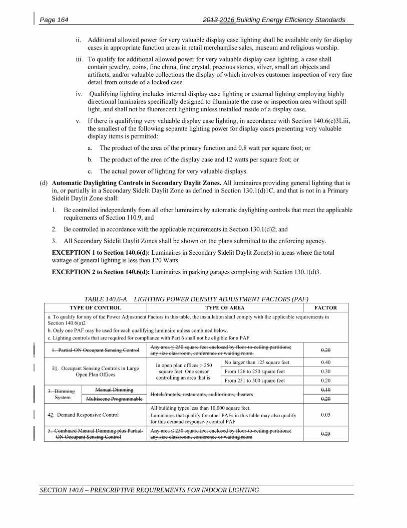
Page 164 2013 2016 Building Energy Efficiency Standards
SECTION 140.6 – PRESCRIPTIVE REQUIREMENTS FOR INDOOR LIGHTING
ii. Additional allowed power for very valuable display case lighting shall be available only for display cases in appropriate function areas in retail merchandise sales, museum and religious worship.
iii. To qualify for additional allowed power for very valuable display case lighting, a case shall contain jewelry, coins, fine china, fine crystal, precious stones, silver, small art objects and artifacts, and/or valuable collections the display of which involves customer inspection of very fine detail from outside of a locked case.
iv. Qualifying lighting includes internal display case lighting or external lighting employing highly directional luminaires specifically designed to illuminate the case or inspection area without spill light, and shall not be fluorescent lighting unless installed inside of a display case.
v. If there is qualifying very valuable display case lighting, in accordance with Section 140.6(c)3Liii, the smallest of the following separate lighting power for display cases presenting very valuable display items is permitted:
a. The product of the area of the primary function and 0.8 watt per square foot; or
b. The product of the area of the display case and 12 watts per square foot; or
c. The actual power of lighting for very valuable displays.
(d) Automatic Daylighting Controls in Secondary Daylit Zones. All luminaires providing general lighting that is in, or partially in a Secondary Sidelit Daylit Zone as defined in Section 130.1(d)1C, and that is not in a Primary Sidelit Daylit Zone shall:
1. Be controlled independently from all other luminaires by automatic daylighting controls that meet the applicable requirements of Section 110.9; and
2. Be controlled in accordance with the applicable requirements in Section 130.1(d)2; and
3. All Secondary Sidelit Daylit Zones shall be shown on the plans submitted to the enforcing agency.
EXCEPTION 1 to Section 140.6(d): Luminaires in Secondary Sidelit Daylit Zone(s) in areas where the total wattage of general lighting is less than 120 Watts.
EXCEPTION 2 to Section 140.6(d): Luminaires in parking garages complying with Section 130.1(d)3.
TABLE 140.6-A LIGHTING POWER DENSITY ADJUSTMENT FACTORS (PAF) TYPE OF CONTROL TYPE OF AREA FACTOR
a. To qualify for any of the Power Adjustment Factors in this table, the installation shall comply with the applicable requirements in Section 140.6(a)2 b. Only one PAF may be used for each qualifying luminaire unless combined below. c. Lighting controls that are required for compliance with Part 6 shall not be eligible for a PAF
1. Partial-ON Occupant Sensing Control Any area ≤ 250 square feet enclosed by floor-to-ceiling partitions; any size classroom, conference or waiting room. 0.20
21. Occupant Sensing Controls in Large Open Plan Offices
In open plan offices > 250 square feet: One sensor
controlling an area that is:
No larger than 125 square feet 0.40
From 126 to 250 square feet 0.30
From 251 to 500 square feet 0.20
3. Dimming System
Manual Dimming Hotels/motels, restaurants, auditoriums, theaters
0.10
Multiscene Programmable 0.20
42. Demand Responsive Control All building types less than 10,000 square feet. Luminaires that qualify for other PAFs in this table may also qualify for this demand responsive control PAF
0.05
5. Combined Manual Dimming plus Partial-ON Occupant Sensing Control
Any area ≤ 250 square feet enclosed by floor-to-ceiling partitions; any size classroom, conference or waiting room 0.25

2013 Building Energy Efficiency Standards Page 165
SECTION 140.6 – PRESCRIPTIVE REQUIREMENTS FOR INDOOR LIGHTING
TABLE 140.6-B COMPLETE BUILDING METHOD LIGHTING POWER DENSITY VALUES
TYPE OF BUILDING ALLOWED LIGHTING POWER DENSITY (WATTS PER SQUARE FOOT)
Auditorium Building 1.51.4
Classroom Building 1.1
Commercial and Industrial Storage Building 0.60
Convention Center Building 1.21.0
Financial Institution Building 1.11.0
General Commercial Building/Industrial Work Building 1.00
Grocery Store Building 1.50
Library Building 1.31.2
Medical Building/Clinic Building 1.11.0
Office Building 0.80
Parking Garage Building 0.20
Religious Facility Building 1.61.5
Restaurant Building 1.21.1
School Building 1.00.95
Theater Building 1.3
All others buildings 0.60.50
TABLE 140.6-C AREA CATEGORY METHOD - LIGHTING POWER DENSITY VALUES (WATTS/FT²)
PRIMARY FUNCTION AREA
ALLOWED LIGHTING
POWER (W/ft²)
PRIMARY FUNCTION AREA ALLOWED LIGHTING POWER (W/ft²)
Auditorium Area 1.51.40 3 Library Area
Reading areas 1.21.1 3
Auto Repair Area 0.90 2 Stack areas 1.5 3
Beauty Salon Area 1.7 Lobby Area
Hotel lobby 1.10.95 3
Civic Meeting Place Area 1.3 3 Main entry lobby 1.50.95 3
Classroom, Lecture, Training, Vocational Areas 1.2 5 Locker/Dressing Room 0.80.70
Commercial and Industrial Storage Areas (conditioned and unconditioned) 0.60 Lounge Area 1.10.90 3
Commercial and Industrial Storage Areas (refrigerated) 0.7 Malls and Atria 1.20.95 3
Convention, Conference, Multipurpose and Meeting Center Areas 1.4 1.2 3 Medical and Clinical Care Area 1.2
Corridor, Restroom, Stair, and Support Areas 0.60
Office Area > 250 square feet 0.75
Dining Area 1.11.0 3 ≤ 250 square feet 1.0
Electrical, Mechanical, Telephone Rooms 0.70.55 2
Parking Garage Area
Parking Area 10 0.14
Exercise Center, Gymnasium Areas 1.0 Dedicated Ramps 0.30
Exhibit, Museum Areas 2.01.8 Daylight Adaptation Zones 9 0.60
Financial Transaction Area 1.21.0 3 Religious Worship Area 1.5 3
General Commercial and Industrial Work Areas
Low bay 0.9 2 Retail Merchandise Sales, Wholesale Showroom Areas 1.2 6 and 7
High bay 1.0 2
Precision 1.2 4 Theater Area
Motion picture 0.90 3
Grocery Sales Area 1.2 6 and 7 Performance 1.4 3

Page 166 2013 2016 Building Energy Efficiency Standards
SECTION 140.6 – PRESCRIPTIVE REQUIREMENTS FOR INDOOR LIGHTING
CONTINUED: TABLE 140.6-C AREA CATEGORY METHOD - LIGHTING POWER DENSITY VALUES (WATTS/FT²)
Hotel Function Area 1.53 Transportation Function Area 1.2
Hotel Function Area 1.43
Transportation Function Area
Concourse & Baggage 0.50
Ticketing 1.0
Kitchen, Food Preparation Areas 1.61.2 Videoconferencing Studio 1.28
Laboratory Area, Scientific 1.41 Waiting Area 1.10.803
Laundry Area 0.90.70 All other areas 0.60.50
Footnotes for this table are listed below.
FOOTNOTES FOR TABLE 140.6-C: See Section 140.6(c)2 for an explanation of additional lighting power available for specialized task work, ornamental, precision, accent, display, decorative, and white boards and chalk boards, in accordance with the footnotes in this table. The smallest of the added lighting power listed in each footnote below, or the actual design wattage, may be added to the allowed lighting power only when using the Area Category Method of compliance.
Footnote number
Type of lighting system allowed Maximum allowed added lighting power. (W/ft2 of task area unless otherwise noted)
1 Specialized task work 0.20 W/ft2
2 Specialized task work 0.50 W/ft2
3 Ornamental lighting as defined in Section 100.1 and in accordance with Section 140.6.(c)2. 0.50 W/ft2
4 Precision commercial and industrial work 1.0 W/ft2
5 Per linear foot of white board or chalk board. 5.5 W per linear foot
6 Accent, display and feature lighting - luminaires shall be adjustable or directional 0.30 W/ft2
7 Decorative lighting - primary function shall be decorative and shall be in addition to general illumination. 0.20 W/ft2
8 Additional Videoconferencing Studio lighting complying with all of the requirements in Section 140.6(c)2Gvii. 1.5 W/ft2
9 Daylight Adaptation Zones shall be no longer than 66 feet from the entrance to the parking garage
10 Additional allowance for ATM locations in Parking Garages. Allowance per ATM.
200 watts for first ATM location. 50 watt for each additional ATM location in a group.
8 Additional Videoconferencing Studio lighting complying with all of the requirements in Section 140.6(c)2Gvii. 1.5 W/ft2
9 Daylight Adaptation Zones shall be no longer than 66 feet from the entrance to the parking garage
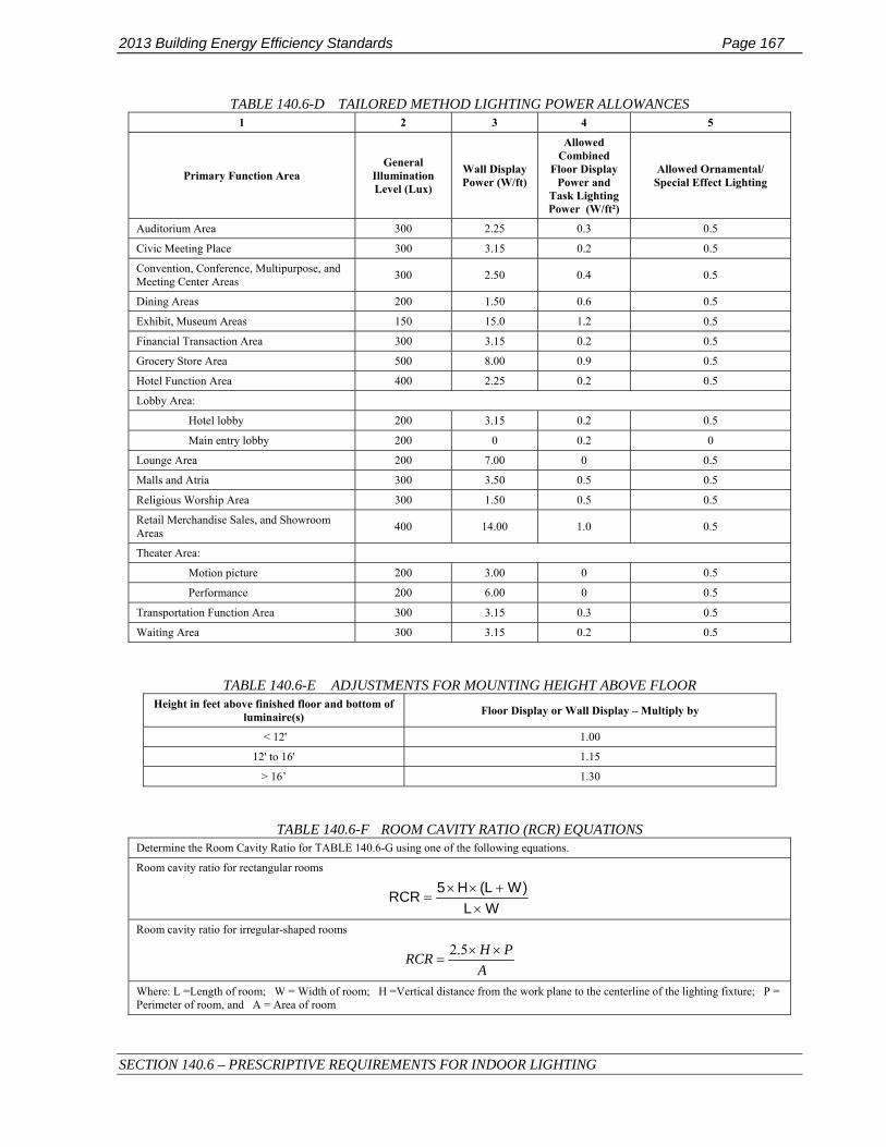
2013 Building Energy Efficiency Standards Page 167
SECTION 140.6 – PRESCRIPTIVE REQUIREMENTS FOR INDOOR LIGHTING
TABLE 140.6-D TAILORED METHOD LIGHTING POWER ALLOWANCES 1 2 3 4 5
Primary Function Area General
Illumination Level (Lux)
Wall Display Power (W/ft)
Allowed Combined
Floor Display Power and
Task Lighting Power (W/ft²)
Allowed Ornamental/ Special Effect Lighting
Auditorium Area 300 2.25 0.3 0.5
Civic Meeting Place 300 3.15 0.2 0.5
Convention, Conference, Multipurpose, and Meeting Center Areas 300 2.50 0.4 0.5
Dining Areas 200 1.50 0.6 0.5
Exhibit, Museum Areas 150 15.0 1.2 0.5
Financial Transaction Area 300 3.15 0.2 0.5
Grocery Store Area 500 8.00 0.9 0.5
Hotel Function Area 400 2.25 0.2 0.5
Lobby Area:
Hotel lobby 200 3.15 0.2 0.5
Main entry lobby 200 0 0.2 0
Lounge Area 200 7.00 0 0.5
Malls and Atria 300 3.50 0.5 0.5
Religious Worship Area 300 1.50 0.5 0.5
Retail Merchandise Sales, and Showroom Areas 400 14.00 1.0 0.5
Theater Area:
Motion picture 200 3.00 0 0.5
Performance 200 6.00 0 0.5
Transportation Function Area 300 3.15 0.3 0.5
Waiting Area 300 3.15 0.2 0.5
TABLE 140.6-E ADJUSTMENTS FOR MOUNTING HEIGHT ABOVE FLOOR Height in feet above finished floor and bottom of
luminaire(s) Floor Display or Wall Display – Multiply by
< 12' 1.00
12' to 16' 1.15
> 16’ 1.30
TABLE 140.6-F ROOM CAVITY RATIO (RCR) EQUATIONS Determine the Room Cavity Ratio for TABLE 140.6-G using one of the following equations.
Room cavity ratio for rectangular rooms
WL)WL(H5RCR
×+××
=
Room cavity ratio for irregular-shaped rooms
APHRCR ××
=5.2
Where: L =Length of room; W = Width of room; H =Vertical distance from the work plane to the centerline of the lighting fixture; P = Perimeter of room, and A = Area of room

Page 168 2013 2016 Building Energy Efficiency Standards
SECTION 140.6 – PRESCRIPTIVE REQUIREMENTS FOR INDOOR LIGHTING
TABLE 140.6-G ILLUMINANCE LEVEL (LUX) POWER DENSITY VALUES (WATTS/FT²)
Illuminance Level (Lux) RCR ≤ 2.0 RCR > 2.0 and ≤ 3.5 RCR > 3.5 and ≤ 7.0 RCR > 7.0
50 0.20.18 0.30.22 0.40.32 0.60.46
100 0.40.30 0.60.38 0.80.56 1.20.84
200 0.60.48 0.80.64 1.30.88 1.91.34
300 0.80.64 1.00.82 1.41.12 2.01.76
400 0.90.78 1.10.98 1.51.34 2.22.08
500 1.00.90 1.21.10 1.61.52 2.42.32
600 1.21.06 1.41.26 2.01.74 2.92.60
700 1.41.24 1.71.46 2.31.98 3.32.96
800 1.61.44 1.91.70 2.62.28 3.83.30
900 1.81.66 2.22.00 3.02.64 4.33.74
1000 1.91.84 2.42.20 3.32.90 4.84.06

2013 Building Energy Efficiency Standards Page 169
SECTION 140.7 – REQUIREMENTS FOR OUTDOOR LIGHTING
SECTION 140.7 – REQUIREMENTS FOR OUTDOOR LIGHTING
(a) An outdoor lighting installation complies with this section if it meets the requirements in Subsections (b) and (c), and the actual outdoor lighting power installed is no greater than the allowed outdoor lighting power calculated under Subsection (d). The allowed outdoor lighting shall be calculated according to Outdoor Lighting Zone in Title 24, Part 1, Section 10-114.
EXCEPTIONS to Section 140.7(a): When more than 50 percent of the light from a luminaire falls within one or more of the following applications, the lighting power for that luminaire shall be exempt from Section 140.7:
1. Temporary outdoor lighting.
2. Lighting required and regulated by the Federal Aviation Administration, and the Coast Guard.
3. Lighting for public streets, roadways, highways, and traffic signage lighting, including lighting for driveway entrances occurring in the public right-of-way.
4. Lighting for sports and athletic fields, and children’s playgrounds.
5. Lighting for industrial sites, including but not limited to, rail yards, maritime shipyards and docks, piers and marinas, chemical and petroleum processing plants, and aviation facilities.
6. Lighting specifically for Automated Teller Machines as required by California Financial Code Section 13040, or required by law through a local ordinance.
76. Lighting of public monuments.
87. Lighting of signs complying with the requirements of Sections 130.3 and 140.8.
98. Lighting of tunnels, bridges, stairs, wheelchair elevator lifts for American with Disabilities Act (ADA) compliance, and ramps that are other than parking garage ramps.
109. Landscape lighting.
1110. In theme parks: outdoor lighting only for themes and special effects.
1211. Lighting for outdoor theatrical and other outdoor live performances, provided that these lighting systems are additions to area lighting systems and are controlled by a multiscene or theatrical cross-fade control station accessible only to authorized operators.
1312. Outdoor lighting systems for qualified historic buildings, as defined in the California Historic Building Code (Title 24, Part 8), if they consist solely of historic lighting components or replicas of historic lighting components. If lighting systems for qualified historic buildings contain some historic lighting components or replicas of historic components, combined with other lighting components, only those historic or historic replica components are exempt. All other outdoor lighting systems for qualified historic buildings shall comply with Section 140.7.
(b) Outdoor Lighting Power Trade-offs. Outdoor lighting power trade-offs shall be determined as follows:
1. Allowed lighting power determined according to Section 140.7(d)1 for general hardscape lighting allowance may be traded to specific applications in Section 140.7(d)2, provided the hardscape area from which the lighting power is traded continues to be illuminated in accordance with Section 140.7(d)1A.
2. Allowed lighting power determined according to Section 140.7(d)2 for additional lighting power allowances for specific applications shall not be traded between specific applications, or to hardscape lighting in Section 140.7(d)1.
3. Trading off lighting power allowances between outdoor and indoor areas shall not be permitted.
(c) Calculation of Actual Lighting Power. The wattage of outdoor luminaires shall be determined in accordance with Section 130.0(c).
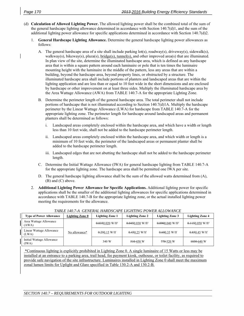
Page 170 2013 2016 Building Energy Efficiency Standards
SECTION 140.7 – REQUIREMENTS FOR OUTDOOR LIGHTING
(d) Calculation of Allowed Lighting Power. The allowed lighting power shall be the combined total of the sum of the general hardscape lighting allowance determined in accordance with Section 140.7(d)1, and the sum of the additional lighting power allowance for specific applications determined in accordance with Section 140.7(d)2.
1. General Hardscape Lighting Allowance. Determine the general hardscape lighting power allowances as follows:
A. The general hardscape area of a site shall include parking lot(s), roadway(s), driveway(s), sidewalk(s), walkway(s), bikeway(s), plaza(s), bridge(s), tunnel(s), and other improved area(s) that are illuminated. In plan view of the site, determine the illuminated hardscape area, which is defined as any hardscape area that is within a square pattern around each luminaire or pole that is ten times the luminaire mounting height with the luminaire in the middle of the pattern, less any areas that are within a building, beyond the hardscape area, beyond property lines, or obstructed by a structure. The illuminated hardscape area shall include portions of planters and landscaped areas that are within the lighting application and are less than or equal to 10 feet wide in the short dimensions and are enclosed by hardscape or other improvement on at least three sides. Multiply the illuminated hardscape area by the Area Wattage Allowance (AWA) from TABLE 140.7-A for the appropriate Lighting Zone.
B. Determine the perimeter length of the general hardscape area. The total perimeter shall not include portions of hardscape that is not illuminated according to Section 140.7(d)1A. Multiply the hardscape perimeter by the Linear Wattage Allowance (LWA) for hardscape from TABLE 140.7-A for the appropriate lighting zone. The perimeter length for hardscape around landscaped areas and permanent planters shall be determined as follows:
i. Landscaped areas completely enclosed within the hardscape area, and which have a width or length less than 10 feet wide, shall not be added to the hardscape perimeter length.
ii. Landscaped areas completely enclosed within the hardscape area, and which width or length is a minimum of 10 feet wide, the perimeter of the landscaped areas or permanent planter shall be added to the hardscape perimeter length.
iii. Landscaped edges that are not abutting the hardscape shall not be added to the hardscape perimeter length.
C. Determine the Initial Wattage Allowance (IWA) for general hardscape lighting from TABLE 140.7-A for the appropriate lighting zone. The hardscape area shall be permitted one IWA per site.
D. The general hardscape lighting allowance shall be the sum of the allowed watts determined from (A), (B) and (C) above.
2. Additional Lighting Power Allowance for Specific Applications. Additional lighting power for specific applications shall be the smaller of the additional lighting allowances for specific applications determined in accordance with TABLE 140.7-B for the appropriate lighting zone, or the actual installed lighting power meeting the requirements for the allowance.
TABLE 140.7-A GENERAL HARDSCAPE LIGHTING POWER ALLOWANCE Type of Power Allowance Lighting Zone 0 Lighting Zone 1 Lighting Zone 2 Lighting Zone 3 Lighting Zone 4
Area Wattage Allowance (AWA)
No allowance*
0.0350.020 W/ft² 0.0450.030 W/ft² 0.0900.040 W/ft² 0.1150.050 W/ft²
Linear Wattage Allowance (LWA) 0.250.15 W/lf 0.450.25 W/lf 0.600.35 W/lf 0.850.45 W/lf
Initial Wattage Allowance (IWA) 340 W 510 450 W 770 520 W 1030 640 W
*Continuous lighting is explicitly prohibited in Lighting Zone 0. A single luminaire of 15 Watts or less may be installed at an entrance to a parking area, trail head, fee payment kiosk, outhouse, or toilet facility, as required to provide safe navigation of the site infrastructure. Luminaires installed in Lighting Zone 0 shall meet the maximum zonal lumen limits for Uplight and Glare specified in Table 130.2-A and 130.2-B.

2013 Building Energy Efficiency Standards Page 171
SECTION 140.7 – REQUIREMENTS FOR OUTDOOR LIGHTING
TABLE 140.7-B ADDITIONAL LIGHTING POWER ALLOWANCE FOR SPECIFIC APPLICATIONS All area and distance measurements in plan view unless otherwise noted.
Lighting Application Lighting Zone 0
Lighting Zone 1
Lighting Zone 2
Lighting Zone 3
Lighting Zone 4
WATTAGE ALLOWANCE PER APPLICATION. Use all that apply as appropriate.
Building Entrances or Exits. Allowance per door. Luminaires qualifying for this allowance shall be within 20 feet of the door.
Not applicable
30 15 watts
60 25 watts
90 35 watts
90 45 watts
Primary Entrances to Senior Care Facilities, Police Stations, Hospitals, Fire Stations, and Emergency Vehicle Facilities. Allowance per primary entrance(s) only. Primary entrances shall provide access for the general public and shall not be used exclusively for staff or service personnel. This allowance shall be in addition to the building entrance or exit allowance above. Luminaires qualifying for this allowance shall be within 100 feet of the primary entrance.
Not applicable
45 20 watts
80 40 watts
120 60 watts
130 80 watts
Drive Up Windows. Allowance per customer service location. Luminaires qualifying for this allowance shall be within 2 mounting heights of the sill of the window.
Not applicable
40 30 watts
75 40 watts
125 60 watts
200 100 watts
Vehicle Service Station Uncovered Fuel Dispenser. Allowance per fueling dispenser. Luminaires qualifying for this allowance shall be within 2 mounting heights of the dispenser.
Not applicable
120 80 watts
175 100 watts
185 140 watts
330 160 watts
ATM Machine Lighting. Allowance per ATM machine. Luminaires qualifying for this allowance shall be within 50 feet of the dispenser.
Not applicable
250 watts for first ATM machine, 70 watts for each additional ATM machine.
WATTAGE ALLOWANCE PER UNIT LENGTH (w/linear ft). May be used for one or two frontage side(s) per site.
Outdoor Sales Frontage. Allowance for frontage immediately adjacent to the principal viewing location(s) and unobstructed for its viewing length. A corner sales lot may include two adjacent sides provided that a different principal viewing location exists for each side. Luminaires qualifying for this allowance shall be located between the principal viewing location and the frontage outdoor sales area.
Not applicable
No Allowance
22.515 W/linear ft
36 25 W/linear ft
45 30 W/linear ft
WATTAGE ALLOWANCE PER HARDSCAPE AREA (W/ft²). May be used for any illuminated hardscape area on the site.
Hardscape Ornamental Lighting. Allowance for the total site illuminated hardscape area. Luminaires qualifying for this allowance shall be rated for 100 watts or less as determined in accordance with Section 130.0(d), and shall be post-top luminaires, lanterns, pendant luminaires, or chandeliers.
Not applicable
No Allowance
0.020.015 W/ft²
0.040.03 W/ft²
0.060.045 W/ft²
WATTAGE ALLOWANCE PER SPECIFIC AREA (W/ft²). Use as appropriate provided that none of the following specific applications shall be used for the same area.
Building Facades. Only areas of building façade that are illuminated shall qualify for this allowance. Luminaires qualifying for this allowance shall be aimed at the façade and shall be capable of illuminating it without obstruction or interference by permanent building features or other objects.
Not applicable
No Allowance
0.180.15 W/ft²
0.350.25 W/ft²
0.500.35 W/ft²
Outdoor Sales Lots. Allowance for uncovered sales lots used exclusively for the display of vehicles or other merchandise for sale. Driveways, parking lots or other non sales areas shall be considered hardscape areas even if these areas are completely surrounded by sales lot on all sides. Luminaires qualifying for this allowance shall be within 5 mounting heights of the sales lot area.
Not applicable
0.1640.100 W/ft²
0.5550.250 W/ft²
0.7580.500 W/ft²
1.2851.000 W/ft²
Vehicle Service Station Hardscape. Allowance for the total illuminated hardscape area less area of buildings, under canopies, off property, or obstructed by signs or structures. Luminaires qualifying for this allowance shall be illuminating the hardscape area and shall not be within a building, below a canopy, beyond property lines, or obstructed by a sign or other structure.
Not applicable
0.0140.010 W/ft²
0.1550.100 W/ft²
0.3080.150 W/ft²
0.4850.200 W/ft²
Vehicle Service Station Canopies. Allowance for the total area within the drip line of the canopy. Luminaires qualifying for this allowance shall be located under the canopy.
Not applicable
0.5140.400 W/ft²
1.0050.700 W/ft²
1.3000.900 W/ft²
2.2001.200 W/ft²
Sales Canopies. Allowance for the total area within the drip line of the canopy. Luminaires qualifying for this allowance shall be located under the canopy.
Not applicable
No Allowance
0.6550.500 W/ft²
0.9080.800 W/ft²
1.1351.000 W/ft²
Non-sales Canopies and Tunnels. Allowance for the total area within the drip line of the canopy or inside the tunnel. Luminaires qualifying for this allowance shall be located under the canopy or tunnel.
Not applicable
0.0840.080 W/ft²
0.2050.160 W/ft²
0.4080.300 W/ft²
0.5850.400 W/ft²

Page 172 2013 2016 Building Energy Efficiency Standards
SECTION 140.7 – REQUIREMENTS FOR OUTDOOR LIGHTING
Guard Stations. Allowance up to 1,000 square feet per vehicle lane. Guard stations provide access to secure areas controlled by security personnel who stop and may inspect vehicles and vehicle occupants, including identification, documentation, vehicle license plates, and vehicle contents. Qualifying luminaires shall be within 2 mounting heights of a vehicle lane or the guardhouse.
Not applicable
0.1540.100 W/ft²
0.3550.300 W/ft²
0.7080.500 W/ft²
0.9850.750 W/ft²
CONTINUED: TABLE 140.7-B ADDITIONAL LIGHTING POWER ALLOWANCE FOR SPECIFIC APPLICATIONS
All area and distance measurements in plan view unless otherwise noted. Lighting Application Lighting
Zone 0 Lighting Zone 1
Lighting Zone 2
Lighting Zone 3
Lighting Zone 4
Student Pick-up/Drop-off zone. Allowance for the area of the student pick-up/drop-off zone, with or without canopy, for preschool through 12th grade school campuses. A student pick-up/drop off zone is a curbside, controlled traffic area on a school campus where students are picked-up and dropped off from vehicles. The allowed area shall be the smaller of the actual width or 25 feet, times the smaller of the actual length or 250 feet. Qualifying luminaires shall be within 2 mounting heights of the student pick-up/drop-off zone.
Not applicable
No Allowance
0.120.10 W/ft²
0.450.25 W/ft²
No Allowance
Outdoor Dining. Allowance for the total illuminated hardscape of outdoor dining. Outdoor dining areas are hardscape areas used to serve and consume food and beverages. Qualifying luminaires shall be within 2 mounting heights of the hardscape area of outdoor dining.
Not applicable
0.0140.010 W/ft²
0.1350.100 W/ft²
0.2400.150 W/ft²
0.4000.200 W/ft²
Special Security Lighting for Retail Parking and Pedestrian Hardscape. This additional allowance is for illuminated retail parking and pedestrian hardscape identified as having special security needs. This allowance shall be in addition to the building entrance or exit allowance.
Not applicable
0.0070.005 W/ft²
0.009 0.007W/ft²
0.0190.012 W/ft²
No Allowance

2013 Building Energy Efficiency Standards Page 173
SECTION 140.8 – REQUIREMENTS FOR SIGNS
SECTION 140.8 – REQUIREMENTS FOR SIGNS This section applies to all internally illuminated and externally illuminated signs, unfiltered light emitting diodes (LEDs), and unfiltered neon, both indoor and outdoor. Each sign shall comply with either Subsection (a) or (b), as applicable.
(a) Maximum Allowed Lighting Power.
1. For internally illuminated signs, the maximum allowed lighting power shall not exceed the product of the illuminated sign area and 12 watts per square foot. For double-faced signs, only the area of a single face shall be used to determine the allowed lighting power.
2. For externally illuminated signs, the maximum allowed lighting power shall not exceed the product of the illuminated sign area and 2.3 watts per square foot. Only areas of an externally lighted sign that are illuminated without obstruction or interference, by one or more luminaires, shall be used.
3. Lighting for unfiltered light emitting diodes (LEDs) and unfiltered neon shall comply with Section 140.8(b).
(b) Alternate Lighting Sources. The sign shall comply if it is equipped only with one or more of the following light sources:
1. High pressure sodium lamps; or
2. Metal halide lamps that are:
A. Pulse start or ceramic served by a ballast that has a minimum efficiency of 88 percent or greater; or
B. Pulse start that are 320 watts or smaller, are not 250 watt or 175 watt lamps, and are served by a ballast that has a minimum efficiency of 80 percent.
Ballast efficiency is the measured output wattage to the lamp divided by the measured operating input wattage when tested according to ANSI C82.6-2005.
3. Neon or cold cathode lamps with transformer or power supply efficiency greater than or equal to following:
A. A minimum efficiency of 75 percent when the transformer or power supply rated output current is less than 50 mA; or
B. A minimum efficiency of 68 percent when the transformer or power supply rated output current is 50 mA or greater.
The ratio of the output wattage to the input wattage is at 100 percent tubing load.
4. Fluorescent lighting systems meeting one of the following requirements:
A. Use only lamps with a minimum color rendering index (CRI) of 80; or
B. Use only electronic ballasts with a fundamental output frequency not less than 20 kHz.
5. Light emitting diodes (LEDs) with a power supply having an efficiency of 80 percent or greater; or
EXCEPTION to Section 140.8(b)5: Single voltage external power supplies that are designed to convert 120 volt AC input into lower voltage DC or AC output, and have a nameplate output power less than or equal to 250 watts, shall comply with the applicable requirements of the Appliance Efficiency Regulations (Title 20).
6. Compact fluorescent lamps that do not contain a medium screw base sockets (E24/E26).
EXCEPTION 1 to Section 140.8: Unfiltered incandescent lamps that are not part of an electronic message center (EMC), an internally illuminated sign, or an externally illuminated sign.
EXCEPTION 2 to Section 140.8: Exit signs. Exit signs shall meet the requirements of the Appliance Efficiency Regulations.
EXCEPTION 3 to Section 140.8: Traffic Signs. Traffic signs shall meet the requirements of the Appliance Efficiency Regulations.

Page 174 2013 2016 Building Energy Efficiency Standards
SECTION 140.9 – PRESCRIPTIVE REQUIREMENTS FOR COVERED PROCESSES
SECTION 140.9 – PRESCRIPTIVE REQUIREMENTS FOR COVERED PROCESSES (a) Prescriptive Requirements for Computer Rooms. A computer room complies with this section by being
designed with and having constructed and installed a cooling system that meets the requirements of Subsections 1 through 6.
1. Economizers. Each individual cooling system primarily serving computer room(s) shall include either:
A. An integrated air economizer capable of providing 100 percent of the expected system cooling load as calculated in accordance with a method approved by the Commission, at outside air temperatures of 55°F dry-bulb/50°F wet-bulb and below; or
B. An integrated water economizer capable of providing 100 percent of the expected system cooling load as calculated in accordance with a method approved by the Commission, at outside air temperatures of 40°F dry-bulb/35°F wet-bulb and below.
EXCEPTION 1 to Section 140.9(a)1: Individual computer rooms under 5 tons in a building that does not have any economizers.
EXCEPTION 2 to Section 140.9(a)1: New cooling systems serving an existing computer room in an existing building up to a total of 50 tons of new cooling equipment per building.
EXCEPTION 3 to Section 140.9(a)1: New cooling systems serving a new computer room in an existing building up to a total of 20 tons of new cooling equipment per building.
EXCEPTION 4 to Section 140.9(a)1: A computer room may be served by a fan system without an economizer if it is also served by a fan system with an economizer that also serves noncomputer room(s) provided that all of the following are met:
i. The economizer system is sized to meet the design cooling load of the computer room(s) when the noncomputer room(s) are at 50 percent of their design load; and
ii. The economizer system has the ability to serve only the computer room(s), e.g. shut off flow to noncomputer rooms when unoccupied; and
iii. The noneconomizer system does not operate when the outside air drybulb temperatures is below 60oF and, the cooling load of the noncomputer room(s) served by the economizer system is less than 50 percent of design load.
2. Reheat. Each computer room zone shall have controls that prevent reheating, recooling and simultaneous provisions of heating and cooling to the same zone, such as mixing or simultaneous supply of air that has been previously mechanically heated and air that has been previously cooled, either by cooling equipment or by economizer systems.
3. Humidification. Nonadiabatic humidification (e.g. steam, infrared) is prohibited. Only adiabatic humidification (e.g. direct evaporative, ultrasonic) is permitted.
4. Power Consumption of Fans. The total fan power at design conditions of each fan system shall not exceed 27 W/kBtu·h of net sensible cooling capacity.
5. Fan Control. Each unitary air conditioner with mechanical cooling capacity exceeding 60,000 Btu/hr and each chilled water fan system shall be designed to vary the airflow rate as a function of actual load and shall have controls and/or devices (such as two-speed or variable speed control) that will result in fan motor demand of no more than 50 percent of design wattage at 66 percent of design fan speed.
6. Containment. Computer rooms with air-cooled computers in racks and with a design load exceeding 175 kW/room shall include air barriers such that there is no significant air path for computer discharge air to recirculate back to computer inlets without passing through a cooling system.
EXCEPTION 1 to Section 140.9(a)6: Expansions of existing computer rooms.
EXCEPTION 2 to Section 140.9(a)6: Computer racks with a design load less than 1 kW/rack.

2013 Building Energy Efficiency Standards Page 175
SECTION 140.9 – PRESCRIPTIVE REQUIREMENTS FOR COVERED PROCESSES
EXCEPTION 3 to Section 140.9(a)6: Equivalent energy performance based on computational fluid dynamics or other analysis.
(b) Prescriptive Requirements for Commercial Kitchens.
1. Kitchen exhaust systems.
A. Replacement air introduced directly into the hood cavity of kitchen exhaust hoods shall not exceed 10percent of the hood exhaust airflow rate.
B. For kitchen/dining facilities having total Type I and Type II kitchen hood exhaust airflow rates greater than 5,000 cfm, each Type I hood shall have an exhaust rate that complies with TABLE 140.9-A. If a single hood or hood section is installed over appliances with different duty ratings, then the maximum allowable flow rate for the hood or hood section shall not exceed the TABLE 140.9-A values for the highest appliance duty rating under the hood or hood section. Refer to ASHRAE Standard 154-2011 for definitions of hood type, appliance duty and next exhaust flow rate.
EXCEPTION 1 to Section 140.9(b)1B: 75 percent of the total Type I and Type II exhaust replacement air is transfer air that would otherwise be exhausted.
EXCEPTION 2 to Section 140.9(b)1B: Existing hoods not being replaced as part of an addition or alteration.
TABLE 140.9-A MAXIMUM NET EXHAUST FLOW RATE, CFM PER LINEAR FOOT OF HOOD LENGTH Type of Hood Light Duty
Equipment Medium Duty
Equipment Heavy Duty Equipment
Extra Heavy Duty Equipment
Wall-mounted Canopy
140 210 280 385
Single Island 280 350 420 490
Double Island 175 210 280 385
Eyebrow 175 175 Not Allowed Not Allowed
Backshelf / Passover 210 210 280 Not Allowed
2. Kitchen ventilation.
A. Mechanically cooled or heated makeup air delivered to any space with a kitchen hood shall not exceed the greater of:
i. The supply flow required to meet the space heating and cooling load; or
ii. The hood exhaust flow minus the available transfer air from adjacent spaces. Available transfer air is that portion of outdoor ventilation air serving adjacent spaces not required to satisfy other exhaust needs, such as restrooms, not required to maintain pressurization of adjacent spaces, and that would otherwise be relieved from the building.
EXCEPTION to Section 140.9(b)2A: Existing kitchen makeup air units not being replaced as part of an addition or alteration.
B. A kitchen/dining facility having a total Type I and Type II kitchen hood exhaust airflow rate greater than 5,000 cfm shall have one of the following:
i. At least 50 percent of all replacement air is transfer air that would otherwise be exhausted; or
ii. Demand ventilation system(s) on at least 75 percent of the exhaust air. Such systems shall:
a. Include controls necessary to modulate airflow in response to appliance operation and to maintain full capture and containment of smoke, effluent and combustion products during cooking and idle; and
b. Include failsafe controls that result in full flow upon cooking sensor failure; and
c. Include an adjustable timed override to allow occupants the ability to temporarily override the system to full flow; and
d. Be capable of reducing exhaust and replacement air system airflow rates to the larger of:

Page 176 2013 2016 Building Energy Efficiency Standards
SECTION 140.9 – PRESCRIPTIVE REQUIREMENTS FOR COVERED PROCESSES
(i) 50 percent of the total design exhaust and replacement air system airflow rates; or
(ii) The ventilation rate required peras specified by Section 120.1.
iii. Listed energy recovery devices with a sensible heat recovery effectiveness of not less than 40 percent on at least 50 percent of the total exhaust airflow; and
iv. A minimum of 75 percent of makeup air volume that is:
a. Unheated or heated to no more than 60°F; and
b. Uncooled or cooled without the use of mechanical cooling.
EXCEPTION to Section 140.9(b)2B: Existing hoods not being replaced as part of an addition or alteration.
3. Kitchen Exhaust System Acceptance. Before an occupancy permit is granted for a commercial kitchen subject to Section 140.9(b), the following equipment and systems shall be certified as meeting the Acceptance Requirements for Code Compliance, as specified by the Reference Nonresidential Appendix NA7. A Certificate of Acceptance shall be submitted to the enforcement agency that certifies that the equipment and systems meet the acceptance requirements specified in NA7.11.
(c) Prescriptive Requirements for Laboratory exhaust systems. For buildings with laboratory exhaust systems where the minimum circulation rate to comply with code or accreditation standards is 10 ACH or less, the design exhaust airflow shall be capable of reducing zone exhaust and makeup airflow rates to the regulated minimum circulation rate, or the minimum required to maintain pressurization requirements, whichever is larger. Variable exhaust and makeup airflow shall be coordinated to achieve the required space pressurization at varied levels of demand and fan system capacity.
EXCEPTION 1 to Section 140.9(c): Laboratory exhaust systems serving zones where constant volume is required by the Authority Having Jurisdiction, facility Environmental Health & Safety department or other applicable code.
EXCEPTION 2 to Section 140.9(c): New zones on an existing constant volume exhaust system.
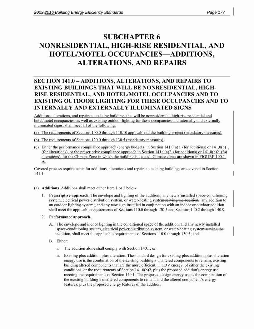
2013 2016 Building Energy Efficiency Standards Page 177
SUBCHAPTER 6 NONRESIDENTIAL, HIGH-RISE RESIDENTIAL, AND
HOTEL/MOTEL OCCUPANCIES—ADDITIONS, ALTERATIONS, AND REPAIRS
SECTION 141.0 – ADDITIONS, ALTERATIONS, AND REPAIRS TO EXISTING BUILDINGS THAT WILL BE NONRESIDENTIAL, HIGH-RISE RESIDENTIAL, AND HOTEL/MOTEL OCCUPANCIES AND TO EXISTING OUTDOOR LIGHTING FOR THESE OCCUPANCIES AND TO INTERNALLY AND EXTERNALLY ILLUMINATED SIGNS Additions, alterations, and repairs to existing buildings that will be nonresidential, high-rise residential and hotel/motel occupancies, as well as existing outdoor lighting for these occupancies and internally and externally illuminated signs, shall meet all of the following:
(a) The requirements of Sections 100.0 through 110.10 applicable to the building project (mandatory measures).
(b) The requirements of Sections 120.0 through 130.5 (mandatory measures).
(c) Either the performance compliance approach (energy budgets) in Section 141.0(a)1. (for additions) or 141.0(b)1. (for alterations), or the prescriptive compliance approach in Section 141.0(a)2. (for additions) or 141.0(b)2. (for alterations), for the Climate Zone in which the building is located. Climate zones are shown in FIGURE 100.1-A.
Covered process requirements for additions, alterations and repairs to existing buildings are covered in Section 141.1.
(a) Additions. Additions shall meet either Item 1 or 2 below.
1. Prescriptive approach. The envelope and lighting of the addition,; any newly installed space-conditioning system, electrical power distribution system, or water-heating system serving the addition,; any addition to an outdoor lighting system,; and any new sign installed in conjunction with an indoor or outdoor addition shall meet the applicable requirements of Sections 110.0 through 130.5 and Sections 140.2 through 140.9.
2. Performance approach.
A. The envelope and indoor lighting in the conditioned space of the addition, and any newly installed space-conditioning system, electrical power distribution system, or water-heating system serving the addition, shall meet the applicable requirements of Sections 110.0 through 130.5; and
B. Either:
i. The addition alone shall comply with Section 140.1; or
ii. Existing plus addition plus alteration. The standard design for existing plus addition, plus alteration energy use is the combination of the existing building’s unaltered components to remain, existing building altered components that are the more efficient, in TDV energy, of either the existing conditions, or the requirements of Section 141.0(b)2, plus the proposed addition's energy use meeting the requirements of Section 140.1. The proposed design energy use is the combination of the existing building’s unaltered components to remain and the altered component’s energy features, plus the proposed energy features of the addition.

Page 178 2013 2016 Building Energy Efficiency Standards
EXCEPTION 1 to Section 141.0(a): When heating, cooling, or service water heating to an addition are provided by expanding existing systems, the existing systems and equipment need not comply with Sections 110.0 through 120.9, or Sections 140.4 through 140.5.
EXCEPTION 2 to Section 141.0(a): Where an existing system with electric reheat is expanded by adding variable air volume (VAV) boxes to serve an addition, total electric reheat capacity may be expanded so that the total capacity does not exceed 150 percent of the existing installed electric heating capacity in any one permit, and the system need not comply with Section 140.4(g). Additional electric reheat capacity in excess of 150 percent of the existing installed electric heating capacity may be added subject to the requirements of the Section 140.4(g).
EXCEPTION 3 to Section 141.0(a): Duct Sealing. When ducts are extended from an existing duct system to serve the addition, the existing duct system and the extended ducts shall meet the applicable requirements specified in Section 141.0(b)2D.
EXCEPTION 4 to Section 141.0(a): Additions that increase the area of the roof by 2,000 square feet or less are exempt from the requirements of Section 110.10.
(b) Alterations. Alterations to existing nonresidential, high-rise residential, or hotel/motel buildings, relocatable public school buildings or alterations in conjunction with a change in building occupancy to a nonresidential, high-rise residential, or hotel/motel occupancy are not subject to Subsection (a) and shall meet item1, and either Item 2 or 3 below:
1. Mandatory Insulation Requirements for Roofs, Walls, and Floors. Altered components in a nonresidential, high-rise residential, or hotel/motel building shall meet the minimum requirements in this Section.
A. Roof/Ceiling Insulation. The opaque portions of the roof/ceiling that separate conditioned spaces from unconditioned spaces or ambient air shall meet the requirements of Section 141.0(b)2Biii.
B. Wall Insulation. For the altered opaque portion of walls separating conditioned spaces from unconditioned spaces or ambient air shall meet the applicable requirements of Items 1 through 4 below:
1. Metal Building. A minimum of R-13 insulation between framing members, or the weighted average U-factor of the wall assembly shall not exceed U-0.113.
2. Metal Framed. A minimum of R-13 insulation between framing members, or the weighted average U-factor of the wall assembly shall not exceed U-0.217.
3. Wood Framed and Others. A minimum of R-11 insulation between framing members, or the weighted average U-factor of the wall assembly shall not exceed U-0.110.
4. Spandrel Panels and Glass Curtain Walls. A minimum of R-4, or the weighted average U-factor of the wall assembly shall not exceed U-0.280.
EXCEPTION to Section 141.0(b)1B: Light and heavy mass walls.
C. Floor Insulation. For the altered portion of raised floors that separate conditioned spaces from unconditioned spaces or ambient air shall meet the applicable requirements of Items 1 through 3 below:
1. Raised Framed Floors. A minimum of R-11 insulation between framing members, or the weighted average U-factor of the floor assembly shall not exceed the U-factor of U-0.071.
2. Raised Mass Floors in High-rise Residential and Hotel/Motel Guest Rooms. A minimum of R-6 insulation, or the weighted average U-factor of the floor assembly shall not exceed the U-factor of U-0.111.
3. Raised Mass Floors in Other Occupancies. No minimum U-factor requirement.
2. Prescriptive approach. The altered components of the envelope, or space conditioning, lighting, electrical power distribution and water heating systems, and any newly installed equipment serving the alteration, shall meet the applicable requirements of Sections 110.0 through 110.9, Sections 120.0 through 120.6, and Sections 120.8 through 130.5; and
EXCEPTION to Section 141.0(b)2: The requirements of Section 120.2(i) shall not apply to alterations of space-conditioning systems or components.

2013 2016 Building Energy Efficiency Standards Page 179
A. Fenestration alterations other than repairs and those subject to Section 141.0(b)2 shall meet the applicable requirements below:
i. For all nonresidential, high-rise residential, and hotel/motel occupancies, when fenestration is altered or where there are alterations that do not increase the fenestration area, all altered fenestration shall meet the requirements of TABLE 141.0-A. When new fenestration area is added to alterations it shall meet the requirements of TABLE 140.3-B, C or D.
EXCEPTION to Section 141.0(b)2Ai: The RSHG and Visible Transmittance (VT) requirement of Table 141.0-A shall not apply when:
1. 150 square feet or less of an entire building's fenestration is replaced, or
2. 50 square feet or less of fenestration area is added, or
3. 50 square feet or less of skylight is added.
Table 141.0-A Altered Window Maximum U-Factor and Minimum RSHGC
B. Existing roofs being replaced, recovered or recoated, of a nonresidential, high-rise residential and hotels/motels shall meet the requirements of Section 110.8(i). Roofs with more than 50 percent of the roof area or more than 2,000 square feet of roof, whichever is less, is being altered the requirements of i through iii below apply:
i. Roofing Products. Nonresidential buildings:
a. Low-sloped roofs in Climate Zones 1 through16 shall have a minimum aged solar reflectance of 0.63 and a minimum thermal emittance of 0.75, or a minimum SRI of 75.
b. Steep-sloped roofs in Climate Zones 1 through16 shall have a minimum aged solar reflectance of 0.20 and a minimum thermal emittance of 0.75, or a minimum SRI of 16.
EXCEPTION to Section 141.0(b)2Bia: An aged solar reflectance less than 0.63 is allowed provided the maximum roof/ceiling U-factor in TABLE 141.0-B is not exceeded.
ii. Roofing Products. High-rise residential buildings and hotels and motels:
a. Low-sloped roofs in Climate Zones 10, 11, 13, 14 and 15 shall have a minimum aged solar reflectance of 0.55 and a minimum thermal emittance of 0.75, or a minimum SRI of 64.
b. Steep-sloped roofs Climate Zones 2 through 15 shall have a minimum aged solar reflectance of 0.20 and a minimum thermal emittance of 0.75, or a minimum SRI of 16.
EXCEPTION 1 to Section 141.0(b)2Bi and ii: Roof area covered by building integrated photovoltaic panels and building integrated solar thermal panels are not required to meet the minimum requirements for solar reflectance, thermal emittance, or SRI.
EXCEPTION 2 to Section 141.0(b)2Bi and ii: Roof constructions that have thermal mass over the roof membrane with a weight of at least 25 lb/ft² are not required to meet the minimum requirements for solar reflectance, thermal emittance, or SRI.
Climate Zone 1 2 3 4 5 6 7 8 9 10 11 12 13 14 15 16
U-factor 0.47 0.47 0.58 0.47 0.58 0.47 0.47 0.47 0.47 0.47 0.47 0.47 0.47 0.47 0.47 0.47
RSHGC 0.41 0.31 0.41 0.31 0.41 0.31 0.31 0.31 0.31 0.31 0.31 0.31 0.31 0.31 0.31 0.41
VT See TABLE 140.3-B, C, and D for all Climate Zones

Page 180 2013 2016 Building Energy Efficiency Standards
Table 141.0-B Roof/Ceiling Insulation Tradeoff for Aged Solar Reflectance
Aged Solar Reflectance
Climate Zone 1, 3‐9
U‐factor
Climate Zone 2, 10‐16
U‐factor
0.62‐ 0.60 0.075 0.052
0.59‐0.55 0.066 0.048
0.54‐0.50 0.060 0.044
0.49‐0.45 0.055 0.041
0.44‐0.40 0.051 0.039
0.39‐0.35 0.047 0.037
0.34‐0.30 0.044 0.035
0.29‐0.25 0.042 0.034
iii. For nonresidential buildings, high-rise residential buildings and hotels/motels, when roofs are exposed to the roof deck, or to the roof recover boards and meets Section 141.0(b)2Bia and iia the exposed area shall be insulated to the levels specified in TABLE 141.0-C.
EXCEPTION to Section 141.0(b)2Biii
a. Existing roofs that are insulated with at least R-7 insulation or that has a U-factor lower than 0.089 are not required to meet the R-value requirement of TABLE 141.0-C.
b. If mechanical equipment is located on the roof and will not be disconnected and lifted as part of the roof replacement, insulation added may be limited to the maximum insulation thickness that will allow a height of 8 inches (203 mm) from the roof membrane surface to the top of the base flashing.
c. If adding the required insulation will reduce the base flashing height to less than 8 inches (203 mm) at penthouse or parapet walls, the insulation added may be limited to the maximum insulation thickness that will allow a height of 8 inches (203 mm) from the roof membrane surface to the top of the base flashing, provided that the conditions in Subsections i through iv apply:
i. The penthouse or parapet walls are finished with an exterior cladding material other than the roofing covering membrane material; and
ii. The penthouse or parapet walls have exterior cladding material that must be removed to install the new roof covering membrane to maintain a base flashing height of 8 inches (203 mm); and
iii. For nonresidential buildings, the ratio of the replaced roof area to the linear dimension of affected penthouse or parapet walls shall be less than 25 square feet per linear foot for Climate Zones 2, and 10 through 16, and less than 100 square feet per linear foot for Climate Zones 1, and 3 though 9; and
iv. For high-rise residential buildings, hotels or motels, the ratio of the replaced roof area to the linear dimension of affected penthouse or parapet walls shall be less than 25 square feet per linear foot for all Climate Zones.

2013 2016 Building Energy Efficiency Standards Page 181
v. Tapered insulation may be used which has a thermal resistance less than that prescribed in TABLE 141.0-C at the drains and other low points, provided that the thickness of insulation is increased at the high points of the roof so that the average thermal resistance equals or exceeds the value that is specified in TABLE 141.0-C.
TABLE 141.0-C INSULATION REQUIREMENTS FOR ROOF ALTERATIONS
Nonresidential High-Rise Residential and Guest Rooms of Hotel/Motel Buildings
Climate Zone
Continuous Insulation
R-value
U-factor
Continuous Insulation
R-value
U-factor
1 R-8 0.082 R-14 0.055
2 R-14 0.055 R-14 0.055
3-9 R-8 0.082 R-14 0.055
10-16 R-14 0.055 R-14 0.055
C. New or Replacement Space-Conditioning Systems or Components other than new or replacement space-conditioning system ducts shall meet the requirements of Section 140.4 applicable to the systems or components being altered.
EXCEPTION 1 to Section 141.0(b)2C. Subsection (b)2C does not apply to replacements of equivalent or lower capacity electric resistance space heaters for high rise residential apartment units.
EXCEPTION 2 to Section 141.0(b)2C. Subsection (b)2C does not apply to replacement of electric reheat of equivalent or lower capacity electric resistance space heaters, when natural gas is not available.
D. Altered Duct Systems. When new or replacement space-conditioning system ducts are installed to serve an existing building, the new ducts shall meet the requirements of Section 120.4. If the space conditioning system meets the criteria of Sections 140.4(l)1, 2, and 3, the duct system shall be sealed as confirmed through field verification and diagnostic testing in accordance with the procedures for duct sealing of an existing duct system as specified in Reference Nonresidential Appendix NA2, to meet one of the following requirements:
i. If the new ducts form an entirely new or replacement duct system directly connected to the air handler, the measured duct leakage shall be equal to, or less than 6 percent of the system air handler airflow as confirmed by field verification and diagnostic testing utilizing the procedures in Reference Nonresidential Appendix Section NA2.1.4.2.1.
Entirely new or replacement duct systems installed as part of an alteration shall be constructed of at least 75 percent new duct material, and up to 25 percent may consist of reused parts from the building's existing duct system (e.g., registers, grilles, boots, air handler, coil, plenums, duct material) if the reused parts are accessible and can be sealed to prevent leakage.
ii. If the new ducts are an extension of an existing duct system, the combined new and existing duct system shall meet one of the following requirements:

Page 182 2013 2016 Building Energy Efficiency Standards
a. The measured duct leakage shall be equal to or less than 15 percent of the system air handler airflow as confirmed by field verification and diagnostic testing utilizing the procedures in Reference Nonresidential Appendix Section NA2.1.4.2.1; or
b. If it is not possible to comply with the duct leakage criterion in Subsection 141.0(b)2Diia, then all accessible leaks shall be sealed and verified through a visual inspection and a smoke test performed by a certified HERS Rater utilizing the methods specified in Reference Nonresidential Appendix NA2.1.4.2.2.
EXCEPTION to Section 141.0(b)2Dii: Duct Sealing. Existing duct systems that are extended, which are constructed, insulated or sealed with asbestos are exempt from the requirements of subsection 141.0(b)2Dii.
E. Altered Space-Conditioning Systems. When a space-conditioning system is altered by the installation or replacement of space-conditioning system equipment (including replacement of the air handler, outdoor condensing unit of a split system air conditioner or heat pump, or cooling or heating coil):
i. For all altered units where the existing thermostat does not comply with Reference Joint Appendix JA5, the existing thermostat shall be replaced with a thermostat that complies with Reference Joint Appendix JA5. All newly installed space-conditioning systems requiring a thermostat shall be equipped with a thermostat that complies with Reference Joint Appendix JA5; and
ii. The duct system that is connected to the new or replaced space-conditioning system equipment shall be sealed, if the duct system meets the criteria of Sections 140.4(l)1, 2 and 3, as confirmed through field verification and diagnostic testing, in accordance with the applicable procedures for duct sealing of altered existing duct systems as specified in Reference Nonresidential Appendix NA2, and conforming to the applicable leakage compliance criteria in Section 141.0(b)2D.
EXCEPTION 1 to Section 141.0(b)2Eii: Duct Sealing. Buildings altered so that the duct system no longer meets the criteria of Sections 144 (l)1, 2, and 3 are exempt from the requirements of Subsection 141.0(b)2Eii.
EXCEPTION 2 to Section 141.0(b)2Eii: Duct Sealing. Duct systems that are documented to have been previously sealed as confirmed through field verification and diagnostic testing in accordance with procedures in the Reference Nonresidential Appendix NA2 are exempt from the requirements of Subsection 141.0(b)2Eii.
EXCEPTION 3 to Section 141.0(b)2Eii: Duct Sealing. Existing duct systems constructed, insulated or sealed with asbestos are exempt from the requirements of Subsection 141.0(b)2Eii.
F. Spaces with lighting systems installed for the first time shall meet the requirements of Sections 110.9, 130.0, 130.1, 130.2, 130.4, 130.5, 140.3(c), 140.6, and 140.7.
G. When the requirements of Section 130.1(d) are triggered by the addition of skylights to an existing building and the lighting system is not recircuited, the daylighting control need not meet the multi-level requirements in Section 130.1(d).
H. New internally and externally illuminated signs shall meet the requirements of Sections 110.9, 130.3 and 140.8.
I. For each enclosed space, alterations to existing indoor lighting shall meet the following requirements:
i. Luminaire Classification and Power shall be determined in accordance with Section 130.0(c).
EXCEPTION to Section 141.0(b)2Ii: For only a Lighting System Alteration in accordance with Section 141.0(b)2Iii, or a Luminaire Modifications-in-Place in accordance with Section 141.0(b)2Iiii; an existing incandescent, fluorescent or HID luminaire may be modified and classified as a luminaire having a different number of, or type of light source(s), provided all of the following conditions are met:
a. The luminaire has been previously used and is in an existing installation; and,
b. The modified luminaire is listed with the different number or type of light source(s) under the installed conditions; and

2013 2016 Building Energy Efficiency Standards Page 183
c. The different light source(s) is not an LED lamp, integrated or nonintegrated type, as defined by ANI/IES RP-16-2010; and
d. The modified luminaire does not contain:
1. Unused fluorescent or HID ballast(s); or
2. Unused HID or fluorescent lamp sockets; or
3. Sockets used only for lamp support; or
4. Screw sockets of any kind or for any purpose; and
e. The wattage of the modified luminaire shall be published in the manufacturer’s catalog based on accredited testing lab reports.
ii. Lighting System Alterations shall meet the applicable requirements in TABLE 141.0-E and the following:
a. Lighting System Alterations include alterations where an existing lighting system is modified, luminaires are replaced, or luminaires are disconnected from the circuit, removed and reinstalled, whether in the same location or installed elsewhere.
EXCEPTION 1 to Section 141.0(b)2Iii: Alterations that qualify as a Luminaire Modification-in-Place.
EXCEPTION 2 to Section 141.0(b)2Iii: Portable luminaires, luminaires affixed to moveable partitions, and lighting excluded in accordance to Section 140.6(a)3.
iii. Luminaire Modifications-in-Place shall meet the applicable requirements in TABLE 141.0-F and the following:
a. To qualify as a Luminaire Modification-in-Place, luminaires shall only be modified by one or more of the following methods:
1. Replacing lamps and ballasts with like type or quantity in a manner that preserves the original luminaire listing.
2. Changing the number or type of light source in a luminaire including: socket renewal, removal or relocation of sockets or lampholders, and/or related wiring internal to the luminaire including the addition of safety disconnecting devices.
3. Changing the optical system of a luminaire in part or in whole.
4. Replacement of whole luminaires one for one in which the only electrical modification involves disconnecting the existing luminaire and reconnecting the replacement luminaire.
b. Luminaire Modifications-In-Place shall include only alterations to lighting system meeting the following conditions:
1. Luminaire Modifications-in-Place shall not be part of or the result of any general remodeling or renovation of the enclosed space in which they are located.
2. Luminaire Modifications-in-Place shall not cause, be the result of, or involve any changes to the panelboard or branch circuit wiring, including line voltage switches, relays, contactors, dimmers and other control devices providing power to the lighting system.
EXCEPTION to Section 141.0(b)2Iiii2. Circuit modifications strictly limited to the addition of occupancy or vacancy sensors and class two lighting controls are permitted for Luminaire Modifications-in-Place
iv. Lighting Wiring Alterations shall meet the applicable requirements in Sections 110.9, 130.1, and 130.4.
a. Lighting Wiring Alterations include the following:
1. Adding a circuit feeding luminaires.
2. Modifying or relocating wiring to provide power to new or relocated luminaires.
3. Replacing wiring between a switch or panelboard and luminaire(s).
4. Replacing or installing a new panelboard feeding lighting systems.

Page 184 2013 2016 Building Energy Efficiency Standards
EXCEPTION to Section 141.0(b)2Iiv. Lighting Wiring Alterations allowed for Luminaire Modifications-in-Place in accordance with Section 141.0(b)2Iiii.
v. Any lighting alteration that increases the installed lighting power in an enclosed space shall meet the requirements of Sections 110.9, 130.0, 130.1, 130.4, 140.3(c) and 140.6.
vi. Lighting Alterations and Luminaire Modifications-in-Place shall not exceed the lighting power allowance in Section 140.6.
vii. The following indoor lighting alterations are not required to comply with the lighting requirements in Title 24, Part 6:
a. Replacement in kind of parts of an existing luminaire that include only new lamps, lamp holders, or lenses, when replacement of those parts is not a Luminaire-Modification-in-Place in accordance with Section 141.0(b)2Iiii.
b. Lighting Alterations directly caused by the disturbance of asbestos.
EXCEPTION to Section 141.0(b)2Iviib: Lighting alterations made in conjunction with asbestos abatement shall comply with the applicable requirements in Section 141.0(b)2I.
I. For each enclosed space, the following lighting system alterations shall not exceed the lighting power allowance in Section 140.6 and shall meet the applicable requirements in TABLE 141.0-E:
i. Replacing luminaires;
ii. Removing and reinstalling luminaires whether in the same location or elsewhere; or
iii. Modifying 40 or more luminaires in any single floor of a building in one or more of the following ways:
a. Replacing the ballasts and associated lamps in the luminaire;
b. Changing the light source of the luminaire; or
c. Changing the optical reflector of the luminaire.
EXCEPTION to Section 141.0(b)2I. Alterations that would directly cause the disturbance of asbestos, unless the alterations are made in conjunction with asbestos abatement.
J. For each enclosed space, the following wiring alterations serving permanently installed lighting shall not exceed the lighting power allowance in Section 140.6 and shall meet the applicable requirements in Section 130.1(a) and (c):
i. Adding a circuit feeding luminaires;
ii. Modifying or relocating wiring to provide power to new or relocated luminaires;
iii. Replacing wiring between a switch or panelboard and luminaires; or
iv. Replacing lighting control panels, panelboards, or branch circuit wiring.
EXCEPTION 1 to Section 141.0(b)2J. Modifications strictly limited to the addition of occupant sensing controls.
EXCEPTION 2 to Section 141.0(b)2J. Alterations that would directly cause the disturbance of asbestos, unless the alterations are made in conjunction with asbestos abatement.
JK. Alterations to existing outdoor lighting systems shall meet the following requirements:
i. Alterations that increase the connected lighting load in a lighting application listed in TABLE 140.7-A or 140.7-B shall meet the applicable requirements of Sections 130.0, 130.2, 130.4, and 140.7; and
ii. In alterations that replace 10 percent or more of the luminaires in a lighting application listed in TABLE 140.7-A or 140.7-B, the altered luminaires shall meet the applicable requirements of Sections 130.0, 130.2 and 130.4; and
2013 2016 Building Energy Efficiency Standards Page 185
iii. In alterations that replace more than 50 percent of the luminaires in a lighting application listed in TABLE 140.7-A or 140.7-B, the lighting in that application shall meet the applicable requirements of Sections 130.0, 130.2, 130.4 and 140.7.
KL. Alterations to existing internally and externally illuminated signs that increase the connected lighting load, replace and rewire more than 50 percent of the ballasts, or relocate the sign to a different location on the same site or on a different site shall meet the requirements of Section 140.8
L. EXCEPTION to Section 141.0(b)2L. Replacement of parts of an existing sign, including replacing lamps, the sign face or ballasts, that do not require rewiring or that are done at a time other than when the sign is relocated, is not an alteration subject to the requirements of Section 141.0(b)2KL.
M. Service water-heating systems shall meet the requirements of Section 140.5, except for the solar water heating requirements.
N. A building shell for which interior walls or ceilings are installed for the first time shall meet the requirements of Section 140.3(c).
O. Electrical Power Distribution Systems. When adding, relocating, or replacing service equipment, circuits, or receptacles, the altered component of the electrical power distribution system shall meet the requirements of Section 130.5.
P. Demand Responsive Controls and Equipment. Alterations where the altered space is larger than 10,000 square feet shall meet the demand responsive control requirements of Section 130.1(e) and 130.5(e).
3. Performance approach.
A. The altered envelope, space–conditioning system, lighting and water heating components, and any newly installed equipment serving the alteration, shall meet the applicable requirements of Sections 110.0 through 110.9, Sections 120.0 through 120.6, and Sections 120.8 through 130.5.
EXCEPTION to Section 141.0(b)3A Window Films. Applied window films installed as part of an alteration complies with the U-factor, RSHGC and VT requirements of TABLE 141.0-D.
B. The standard design for an altered component shall be the higher efficiency of existing conditions or the requirements stated in TABLE 141.0-D. For components not being altered, the standard design shall be based on the existing conditions. When the third party verification option is specified, all components proposed for alteration must be verified. The Executive Director shall determine the qualifications required by the third party inspector.

Page 186 2013 2016 Building Energy Efficiency Standards
TABLE 141.0-D – The Standard Design For An Altered Component Altered Component Standard Design Without Third Party
Verification of Existing Conditions Shall be Based On
Standard Design With Third Party Verification of Existing Conditions Shall be Based On
Roof/Ceiling Insulation, Wall Insulation, and
Floor/Soffit Insulation The requirements of Section 141.0(b)1.
Fenestration The allowed glass area shall be the smaller of the a. or b. below:
a. The proposed glass area: or b. The larger of:
1.The existing glass area that remains; or
2.The area allowed in Section 140.3(a)5A.
The U-factor and RSHGC requirements of TABLE 141.0-A. The existing U-factor and RSHGC levels.
Space-Conditioning System Equipment and Ducts
The requirements of Sections 141.0(b)2C, 141.0(b)2Di or Section 141.0(b)2Dii, and Section 141.0(b)2E.
Window Film The U-factor of 0.40 and SHGC value of 0.35. The existing fenestration in the alteration shall be based on TABLE 110.6-A and Table 110.6-
B.
Service Water Heating Systems The requirements of Section 140.5 without solar water heating requirements.
Roofing Products The requirements of Section 141.0(b)2B.
Lighting System The requirements of Sections 141.0(b)2F, through 141.0(b)2K.
All Other Measures The proposed efficiency levels.
C. The proposed design shall be based on the actual values of the altered components.
NOTES TO SECTION 141.0(b)3:
1. If an existing component must be replaced with a new component, that component is considered an altered component for the purpose of determining the energy budget and must meet the requirements of Section 141.0(b)3.
2. The standard design shall assume the same geometry and orientation as the proposed design.
3. The “existing efficiency level’ modeling rules, including situations where nameplate data is not available, are described in the Nonresidential ACM Reference Manual.
EXCEPTION 1 to Section 141.0(b): When heating, cooling or service water heating for an alteration are provided by expanding existing systems, the existing systems and equipment need not comply with Sections 110.0 through 120.9 and Section 140.4 or 140.5.
EXCEPTION 2 to Section 141.0(b): When existing heating, cooling or service water heating systems or components are moved within a building, the existing systems or components need not comply with Sections 110.0 through 120.9 and Section 140.4 or 140.5.
EXCEPTION 3 to Section 141.0(b): Where an existing system with electric reheat is expanded when adding variable air volume (VAV) boxes to serve an alteration, total electric reheat capacity may be expanded not to exceed 20 percent of the existing installed electric capacity in any one permit and the system need not comply with Section 140.4(g). Additional electric reheat capacity in excess of 20 percent may be added subject to the requirements of the Section 140.4(g).
Relocation or moving of a relocatable public school building is not considered an alteration for the purposes of complying with Title 24, Part 6. If an alteration is made to envelope, space–conditioning system, lighting or water heating components of a relocatable public school building, the alteration is subject to Section 141.0(b).
(c) Repairs. Repairs shall not increase the preexisting energy consumption of the repaired component, system, or equipment.

2013 2016 Building Energy Efficiency Standards Page 187
(d) Alternate Method of Compliance. Any addition, alteration, or repair may comply with the requirements of Title 24, Part 6 by meeting the applicable requirements for the entire building.

Page 188 2013 2016 Building Energy Efficiency Standards
TABLE 141.0-E Requirements for Lighting Alterations
Mandatory control requirements that shall be met when 10% or more of existing luminaires are altered
Resulting lighting power, compared to the lighting power allowance specified in Section 140.6(c)2
Lighting power is ≤ 85% of allowance
Lighting power is > 85% to 100% of allowance
Section 130.1(a) Area Controls Yes Yes
Section 130.1(b) Multi-Level Lighting Controls
Minimum one step between 30-70 percent regardless
of luminaire type, or meet Table 130.1-A
Meet Table 130.1-A
Section 130.1(c) Shut-Off Controls Yes Yes
Section 130.1(d) Automatic Daylight Controls Not Required Yes - only for altered luminaires
Section 130.1(e) Demand Responsive Controls Not Required Yes - only for alterations > 10,000 ft2 in a single
building
TABLE 141.0-E Requirements for Luminaire Alterations Quantity of existing affected luminaires
per Enclosed Space 1 Resulting Lighting Power for
Each Enclosed Space
Applicable Mandatory Control Provisions for Each
Enclosed Space
Multi-level Lighting Control Requirements for Each Altered
Luminaire
Alterations that do not change the area of the enclosed space or the space type
Sum total < 10% of existing luminaires
Existing lighting power is permitted
Existing provisions are permitted Existing controls are permitted
Sum total ≥ 10% of existing luminaires
≤ 85% of allowed lighting power per Section 140.6 Area Category
Method
§130.1(a), (c)
Two level lighting control 2
or §130.1(b)
> 85% of allowed lighting power per Section 140.6 Area Category
Method
§130.1(a), (c), (d) 3
§130.1(b)
Alterations that change the area of the enclosed space or the space type or increase the lighting power in the enclosed space
Any number Comply with Section 140.6 §130.0(d) 3
§130.1(a), (c), (d) 3, (e) §130.1(b)
1. Affected luminaires include any luminaire that is changed, replaced, removed, relocated; or, connected to, altered or revised wiring, except as permitted by EXCEPTIONS 1 and 2 to Section 141.0(b)2Iii: 2. Two level lighting control shall have at least one control step between 30 percent and 70 percent of design lighting power in a manner providing reasonably uniform illuminations 3. Daylight controls in accordance with Section 130.0(d) are required only for luminaires that are altered.
TABLE 141.0-F Requirements for Luminaire Modifications-in-Place

2013 2016 Building Energy Efficiency Standards Page 189
For compliance with this Table, building space is defined as any of the following: 1. A complete single story building 2. A complete floor of a multifloor building 3. The entire space in a building of a single tenant under a single lease 4. All of the common, not leasable space in single building
Quantity of affected luminaires per Building
Space per annum
Resulting Lighting Power per Each Enclosed Space Where ≥ 10% of Existing Luminaires
are Luminaire Modifications-in-Place
Applicable mandatory control provisions for each enclosed space 1
Applicable multi-level lighting control requirements for each
modified luminaire 2
Sum total < 40 Luminaire Modifications-in-Place
Existing lighting power is permitted
Existing provisions are permitted Existing controls are permitted
Sum total ≥ 40 Luminaire Modifications-in-Place
≤ 85% of allowed lighting power per Section 140.6 Area Category
Method
§130.1(a), (c)
Two level lighting control 3
Or §130.1(b)
> 85% of allowed lighting power per Section 140.6 Area Category
Method
§130.0(d) 4
§130.1(a), (c), (d) 4
§130.1(b)
1. Control requirements only apply to enclosed spaces for which there are Luminaire Modifications-in-Place. 2. Multi-level controls are required only for luminaires for which there are Luminaire Modifications-in-Place. 3. Two level lighting control shall have at least one control step between 30 percent and 70 percent of design lighting power in a manner providing reasonably uniform illuminations. 4. Daylight controls in accordance with Section 130.0(d) are required only for luminaires that are modified-in-place.
SECTION 141.1 – REQUIREMENTS FOR COVERED PROCESSES IN ADDITIONS, ALTERATIONS TO EXISTING BUILDINGS THAT WILL BE NONRESIDENTIAL, HIGH-RISE RESIDENTIAL, AND HOTEL/MOTEL OCCUPANCIES Covered processes in additions or alterations to existing buildings that will be nonresidential, high-rise residential, and hotel/motel occupancies shall comply with the applicable subsections of section 120.6.
(a) Refrigerated Warehouses. A refrigerated warehouse complies with this section if it complies with the applicable requirements of Sections 120.6(a).
(b) Commercial Refrigeration. Commercial refrigeration systems comply with this section if they comply with the applicable requirements of Sections 120.6(b).
(c) Enclosed Parking Garages. An enclosed parking garage complies with this section if it complies with the applicable requirements of Sections 120.6(c).
(d) Process Boilers. A process boiler complies with this section if it complies with the applicable requirements of Sections 120.6(d).
(e) Compressed Air Systems. Compressed air systems comply with this section if they comply with the applicable requirements of Sections 120.6(e).

Page 190 2013 2016 Building Energy Efficiency Standards
(This page left intentionally blank)

2013 Building Energy Efficiency Standards Page 191
SUBCHAPTER 7 LOW-RISE RESIDENTIAL BUILDINGS – MANDATORY
FEATURES AND DEVICES
SECTION 150.0 – MANDATORY FEATURES AND DEVICES Any newly constructed low-rise residential building shall meet the requirements of this Section
(a) Ceiling and Rafter Roof Insulation. The opaque portions of ceilings and roofs separating conditioned spaces from unconditioned spaces or ambient air shall meet the requirements of Items 1 or 2through 3 below:
1. Ceilings and rafter roofs sShall be insulated to achieve a weighted average U-factor not exceeding U-0.031 or shall be insulated between wood-framing members with insulation resulting in an installed thermal resistance of R-30 or greater for the insulation alone; and. Attic access doors shall have permanently attached insulation using adhesive or mechanical fasteners. The attic access shall be gasketed to prevent air leakage.
EXCEPTION to Section 150.0(a)1: Insulation ofCeilings and rafter roofs in an alteration shall be insulated to achieve a weighted average U-factor not exceeding 0.054 or shall be insulated between wood-framing members with insulation resulting in an installed thermal resistance of R-19 or greater.
2. Attic access doors shall have permanently attached insulation using adhesive or mechanical fasteners. The attic access shall be gasketed to prevent air leakage; and.The weighted average U-factor shall not exceed 0.031 that would result from installing R-30 insulation between wood-framing members.
3. Insulation shall be installed in direct contact with a continuous roof or ceiling which is sealed to limit infiltration and exfiltration as specified in Section 110.7, including but not limited to placing insulation either above or below the roof deck or on top of a drywall ceiling; and
4. Insulation shall be installed below the roofing membrane or layer used to seal the roof from water penetration unless the insulation has a maximum water absorption of 0.3 percent by volume when tested according to ASTM Standard C272.
(b) Loose-fill Insulation. When loose-fill insulation is installed, the minimum installed weight per square foot shall conform with the insulation manufacturer's installed design weight per square foot at the manufacturer's labeled R-value.
(c) Wall Insulation. Insulation installed in oOpaque portions of above grade framed walls separating conditioned spaces from unconditioned spaces or ambient air shall meet the requirements of Items 1, 2 andor 3 below:
1. Walls of 2x4 inch framing shall shall have an overall assembly U-factor not exceeding U-0.102 or an installed R-value of 13 in a wood framed assembly.
be insulated between framing members with insulation having an installed thermal resistance of not less than R-13 in 2x4 inch framing, or the U-factor shall not exceed U-0.102 that results from installing R-13 in a 2x4 inch wood framed assembly; and
EXCEPTION to Section 150.0(c)1: Existing walls already insulated to an installed a U-factor not exceeding U-0.110 or already insulated between framing members with insulation having an installed thermal resistance of R-11 or greater.
2. Walls of 2x6 inch or greater framing shall have an overall assembly U-factor not exceeding U-0.074 or an installed R-value of 19 in a wood framed assembly.Walls shall be insulated between framing members with insulation having an installed thermal resistance of not less than R-19 in framing of 2x6 inch or greater, or the U-factor shall not exceed the U-0.074 that results from installing R-19 in a 2x6 inch or greater wood framed assembly.; and

Page 192 2013 2016 Building Energy Efficiency Standards
3. Bay or Bow Window roofs and floors shall be insulated to meet the wall insulation requirements of TABLE 150.1-A.
(d) Raised-floor Insulation. Raised floors separating conditioned space from unconditioned space or ambient air shall meet the requirements of 1 or 2 below:
1. Floors shall have an overall assembly U-factor not exceeding U-0.037 or an installed R-value of 19 or greater in a wood framed assembly.
be insulated between wood-framing members with insulation having an installed thermal resistance of R-19 or greater.
2. The weighted average U-factor of floor assemblies shall not exceed 0.037 that would result from installing R-19 insulation between wood-framing members and accounting for the effects of framing members.
EXCEPTION to Section 150.0(d): A building with a controlled ventilation or unvented crawlspace may omit raised floor insulation if all of the following are met:
A. The foundation walls are insulated to meet the wall insulation minimums as shown in TABLE 150.1-A; and
B. A Class I or Class II vapor retarder is placed over the entire floor of the crawlspace; and
C. Vents between the crawlspace and outside air are fitted with automatically operated louvers that are temperature actuated; and
D. The requirements in Reference Residential Appendix RA4.5.1.
(e) Installation of Fireplaces, Decorative Gas Appliances and Gas Logs
1. If a masonry or factory-built fireplace is installed, it shall have the following:
A. Closeable metal or glass doors covering the entire opening of the firebox; and
B. A combustion air intake to draw air from the outside of the building, which is at least 6 square inches in area and is equipped with a readily accessible, operable, and tight-fitting damper or combustion-air control device; and
EXCEPTION to Section 150.0(e)1B: An outside combustion-air intake is not required if the fireplace will be installed over concrete slab flooring and the fireplace will not be located on an exterior wall.
C. A flue damper with a readily accessible control.
EXCEPTION to Section 150.0(e)1C: When a gas log, log lighter, or decorative gas appliance is installed in a fireplace, the flue damper shall be blocked open if required by the CMC or the manufacturer's installation instructions.
2. Continuous burning pilot lights and the use of indoor air for cooling a firebox jacket, when that indoor air is vented to the outside of the building, are prohibited.
(f) Slab Edge Insulation. Material used for slab edge insulation shall meet the following minimum specifications:
1. Water absorption rate for the insulation material alone without facings no greater than 0.3 percent when tested in accordance with Test Method A – 24-Hour-Immersion of ASTM C272.
2. Water vapor permeance no greater than 2.0 perm/inch when tested in accordance with ASTM E96.
3. Concrete slab perimeter insulation shall be protected from physical damage and ultraviolet light deterioration.
4. Insulation for a heated slab floor shall meet the requirements of Section 110.8(g).
RESERVED
(g) Vapor Retarder
1. In Climate Zones 14 and 16 a Class I or Class II vapor retarder shall be installed on the conditioned space side of all insulation in all exterior walls, vented attics and unvented attics with air-permeable insulation; and

2013 Building Energy Efficiency Standards Page 193
2A. In Climate Zones 1-16 with unvented crawl spaces the earth floor of the crawl space shall be covered with a Class I or Class II vapor retarder; or
3B. In a building having a controlled ventilation crawl space, a Class I or Class II vapor retarder shall be placed over the earth floor of the crawl space to reduce moisture entry and protect insulation from condensation, as specified in the exception to Section 150.0(d).
(h) Space-Conditioning Equipment.
1. Building Cooling and Heating Loads. Building heating and cooling loads shall be determined using a method based on any one of the following:
A. The ASHRAE Handbook, Equipment Volume, Applications Volume, and Fundamentals Volume; or
B. The SMACNA Residential Comfort System Installation Standards Manual; or
C. The ACCA Manual J.
The cooling and heating loads are two of the criteria that shall be used for equipment sizing and selection.
NOTE: Heating systems are required to have a minimum heating capacity adequate to meet the minimum requirements of the CBC. The furnace output capacity and other specifications are published in the Commission's directory of certified equipment or other directories approved by the Commission.
2. Design conditions. For the purpose of sizing the space-conditioning (HVAC) system, the indoor design temperatures shall be 68°F for heating and 75°F for cooling. Outdoor design conditions shall be selected from Reference Joint Appendix JA2, which is based on data from the ASHRAE Climatic Data for Region X. The outdoor design temperatures for heating shall be no lower than the Heating Winter Median of Extremes values. The outdoor design temperatures for cooling shall be no greater than the 1.0 percent Cooling Dry Bulb and Mean Coincident Wet Bulb values.
3. Outdoor Condensing Units.
A. Clearances. Installed air conditioner and heat pump outdoor condensing units shall have a clearance of at least five (5) feet (1.5 meters) from the outlet of any dryer vent.
A.B. Liquid Line Drier. Installed air conditioner and heat pump systems shall be equipped with liquid line filter driers if required as specified by manufacturer’s instructions.
4. Central Forced-Air Heating Furnaces.
A. Temperature Rise. Central forced-air heating furnace installations shall be configured to operate in conformance with the furnace manufacturer's maximum inlet-to-outlet temperature rise specifications.
(i) Thermostats. Heating systems shall be equipped with thermostats that meet the requirements of Section 110.2(c).
(j) Water System Piping and Insulation for Piping, Tanks, and Cooling System Lines.
1. Storage tank insulation.
A. Storage gas water heaters with an energy factor equal to or less than the federal minimum standards shall be externally wrapped with insulation having an installed thermal resistance of R-12 or greater.
AB. Unfired hot water tanks, such as storage tanks and backup storage tanks for solar water-heating systems, shall be externally wrapped with insulation having an installed thermal resistance of R-12 or greater or have internal insulation of at least R-16 and a label on the exterior of the tank showing the insulation R-value.
2. Water piping and cooling system line insulation thickness and conductivity. Piping shall be insulated to the thicknesses as follows:
A. All domestic hot water system piping conditions listed below, whether buried or unburied, must be insulated and the insulation thickness shall be selected based on the conductivity range in TABLE 120.3-A and the insulation level shall be selected from the fluid temperature range based on the thickness requirements in TABLE 120.3-A:
i. The first 5 feet (1.5 meters) of hot and cold water pipes from the storage tank.

Page 194 2013 2016 Building Energy Efficiency Standards
ii. All piping with a nominal diameter of 3/4 inch (19 millimeter) or larger.
iii. All piping associated with a domestic hot water recirculation system regardless of the pipe diameter.
iv. Piping from the heating source to storage tank or between tanks.
v. Piping buried below grade..
vi. All hot water pipes from the heating source to the kitchen fixtures.
B. In addition to insulation requirements, all domestic hot water pipes that are buried below grade must be installed in a water proof and non-crushable casing or sleeve that allows for installation, removal, and replacement of the enclosed pipe and insulation.
C. Pipe for cooling system lines shall be insulated as specified in Subsection A. Piping for steam and hydronic heating systems or hot water systems with pressure above 15 psig (103 kPa) shall meet the requirements in TABLE 120.3-A.
EXCEPTION 1 to Section 150.0(j)2: Factory-installed piping within space-conditioning equipment certified under Section 110.1 or 110.2.
EXCEPTION 2 to Section 150.0(j)2: Piping that serves process loads, gas piping, cold domestic water piping, condensate drains, roof drains, vents, or waste piping.
EXCEPTION 3 to Section 150.0(j)2: Piping that penetrates framing members shall not be required to have pipe insulation for the distance of the framing penetration. Metal piping that penetrates metal framing shall use grommets, plugs, wrapping or other insulating material to assure that no contact is made with the metal framing. Insulation shall butt securely against all framing members.
EXCEPTION 4 to Section 150.0(j)2: Piping installed in interior or exterior walls shall not be required to have pipe insulation if all of the requirements are met for compliance with Quality Insulation Installation (QII) as specified in the Reference Residential Appendix RA3.5.
EXCEPTION 5 to Section 150.0(j)2: Piping installed in attics with a minimum of 4 inches (10 cm) of attic insulation on top of the piping shall not be required to have pipe insulation.
NOTE: Where the Executive Director approves a water heater calculation method for particular water heating recirculation systems, piping insulation requirements are those specified in the approved calculation method.
3. Insulation Protection. Insulation outside conditioned space shall be protected from damage, including that due to sunlight, moisture, equipment maintenance, and wind. Protection includes but is not limited to the following:
A. Insulation exposed to weather shall either be rated for outdoor use or installed with a cover suitable for outdoor service; e.g., protected by aluminum, sheet metal, painted canvas, or plastic cover. Cellular foam insulation shall be protected as above or painted with a coating that is water retardant and provides shielding from solar radiation that can cause degradation of the material.
B. Insulation covering chilled water piping and refrigerant suction piping located outside the conditioned space shall have a Class I or Class II vapor retarding facing, or the insulation shall be installed at the thickness that qualifies as a Class I or Class II vapor retarder.
(k) Residential Lighting.
1. Luminaire Requirements
A. Luminaire Efficacy: Installed All installed luminaires shall be classified as high-efficacy or low-efficacy for compliance with Section 150.0(k) in accordance with TABLE 150.0-A or TABLE 150.0-B, as applicable.
B. Hybrid Luminaires: When a high efficacy and low efficacy lighting system are combined together in a single luminaire, the high efficacy and low efficacy lighting systems shall separately comply with the applicable provisions of Section 150.0(k)Blank Electrical Boxes. .The number of electrical boxes that are more than 5 feet above the finished floor and do not contain a luminaire or other device shall be no

2013 Building Energy Efficiency Standards Page 195
greater than the number of bedrooms. These electrical boxes must be served by a dimmer or vacancy sensor control.
C. Luminaire Wattage and Classification. The Wattage and Classification of permanently installed luminaires in residential kitchens shall be determined in accordance with Section 130.0(c). In residential kitchens, the wattage of electrical boxes finished with a blank cover or where no electrical equipment has been installed, and where the electrical box can be used for a luminaire or a surface mounted ceiling fan, shall be calculated as 180 watts of low efficacy lighting per electrical box.Recessed Luminaires in Ceilings. Luminaires recessed into ceilings shall meet all of the following requirements:
i. Be listed, as defined in Section 100.1, for zero clearance insulation contact (IC) by Underwriters Laboratories or other nationally recognized testing/rating laboratory; and
ii. Have a label that certifies the luminaire is airtight with air leakage less than 2.0 CFM at 75 Pascals when tested in accordance with ASTM E283. An exhaust fan housing shall not be required to be certified airtight; and
iii. Be sealed with a gasket or caulk between the luminaire housing and ceiling, and shall have all air leak paths between conditioned and unconditioned spaces sealed with a gasket or caulk; and
iv. For luminaires with hardwired ballasts or drivers, allow ballast or driver maintenance and replacement to be readily accessible to building occupants from below the ceiling without requiring the cutting of holes in the ceiling; and
v. Shall not contain screw based lamps; and
i.vi. Shall contain light sources that comply with Reference Joint Appendix JA8, including the elevated temperature requirements of JA8.10, and shall not contain light sources that are labeled “not for use in enclosed fixtures” or “not for use in recessed fixtures.”
D. Electronic Ballasts. Ballasts for fluorescent lamps rated 13 watts or greater shall be electronic and shall have an output frequency no less than 20 kHz.
E. Night Lights. Permanently installed night lights and night lights integral to installed luminaires or exhaust fans shall be rated to consume no more than five watts of power per luminaire or exhaust fan as determined in accordance with Section 130.0(c). Night lights shall not be required to be controlled by vacancy sensors.
F. Lighting Integral to Exhaust Fans. Lighting integral to exhaust fans shall meet the applicable requirements of Section 150.0(k).
EXCEPTION to Section 150.0(k)1F: Lighting installed by the manufacturer in kitchen exhaust hoods.
G. Screw based luminaires. Screw based luminaires shall meet all of the following requirements:
i. The luminaires shall not be recessed luminaires; and
ii. The luminaires shall contain lamps that comply with Reference Joint Appendix JA8; and
iii. The installed lamps shall be labeled as compliant with JA8.
EXCEPTION to Section 150.1(k)1G: Lurminaires with hard-wired ballasts for high intensity discharge lamps.
2. Interior Lighting Switching Devices and Controls.
A. High efficacy luminaires shall be switched separately from low efficacy luminairesAll phase cut dimmers shall comply with NEMA SSL 7A.
B. Exhaust fans shall be switched separately from lighting systems.
EXCEPTION to Section 150.0(k)2B: Lighting integral to an exhaust fan may be on the same switch as the fan provided the lighting can be switched OFF in accordance with the applicable provisions in Section 150.0(k)2 while allowing the fan to continue to operate for an extended period of time.

Page 196 2013 2016 Building Energy Efficiency Standards
C. Luminaires shall be switched with readily accessible controls that permit the luminaires to be manually switched ON and OFF.
D. Lighting controls and equipment shall be installed in accordance with the manufacturer's instructions.
E. No controls shall bypass a dimmer or vacancy sensor function where that dimmer or vacancy sensor has been installed to comply with Section 150.0(k).
F. Lighting controls shall comply with the applicable requirements of Section 110.9.
G. An Energy Management Control System (EMCS) may be used to comply with dimmer requirements in Section 150.0(k) if at a minimum it provides the functionality of a dimmer in accordance with Section 110.9, meets the installation certificate requirements in Section 130.4, the EMCS requirements in Section 130.5, and complies with all other applicable requirements in Section 150.0(k)2.
H. An Energy Management Control System (EMCS) may be used to comply with vacancy sensor requirements in Section 150.0(k) if at a minimum it provides the functionality of a vacancy sensor in accordance with Section 110.9, meets the installation certificate requirements in Section 130.4, the EMCS requirements in Section 130.5, and complies with all other applicable requirements in Section 150.0(k)2.
I. A multiscene programmable controller may be used to comply with dimmer requirements in Section 150.0(k) if at a minimum it provides the functionality of a dimmer in accordance with Section 110.9, and complies with all other applicable requirements in Section 150.0(k)2.
J. In Bathrooms, Garages, Laundry Rooms, and Utility Rooms, at least one luminaire in each of these spaces shall be controlled by a vacancy sensor.
K. Dimmers or vacancy sensors shall control all luminaires required to have light sources compliant with Reference Joint Appendix JA8.
EXCEPTION 1 to Section 150.0(k)2K: Luminaires in closets less than 70 square feet.
EXCEPTION 2 to Section 150.0(k)2K: Luminaires in hallways.
3. Lighting in Kitchens.
A. A minimum of 50 percent of the total rated wattage of permanently installed lighting in kitchens shall be high efficacy.
B. For the purpose of compliance with Section 150.0(k), kitchen lighting includes all permanently installed lighting in the kitchen except for lighting that is internal to cabinets for the purpose of illuminating only the inside of the cabinets. Lighting in areas adjacent to the kitchen, including but not limited to dining and nook areas, are considered kitchen lighting if they are not separately switched from kitchen lighting.
EXCEPTION to Section 150.0(k)3: Up to 50 watts for dwelling units less than or equal to 2,500 ft² or 100 watts for dwelling units larger than 2,500 ft² may be exempt from the 50 percent high efficacy requirement when all lighting in the kitchen is controlled in accordance with the applicable provisions in Section 150.0(k)2, and is also controlled by vacancy sensors or dimmers.
4. Lighting Internal to Cabinets. Permanently installed lighting that is internal to cabinets shall use no more than 20 watts of power per linear foot of illuminated cabinet. The length of an illuminated cabinet shall be determined using one of the following measurements, regardless of the number of shelves or the number of doors per cabinet section:
A. One horizontal length of illuminated cabinet; or
B. One vertical length, per illuminated cabinet section; or
C. No more than one vertical length per every 40 horizontal inches of illuminated cabinet.
5. Lighting in Bathrooms. Lighting installed in bathrooms shall meet the following requirements:
A. A minimum of one high efficacy luminaire shall be installed in each bathroom; and
B. All other lighting installed in each bathroom shall be high efficacy or controlled by vacancy sensors.

2013 Building Energy Efficiency Standards Page 197
6. Lighting in Garages, Laundry Rooms, and Utility Rooms. Lighting installed in attached and detached garages, laundry rooms, and utility rooms shall be high efficacy luminaires and controlled by vacancy sensors.
7. Lighting other than in Kitchens, Bathrooms, Garages, Laundry Rooms, and Utility Rooms. Lighting installed in rooms or areas other than in kitchens, bathrooms, garages, laundry rooms, and utility rooms shall be high efficacy, or shall be controlled by either dimmers or vacancy sensors.
EXCEPTION 1 to Section 150.0(k)7: Luminaires in closets less than 70 square feet.
EXCEPTION 2 to Section 150.0(k)7: Lighting in detached storage buildings less than 1,000 square feet located on a residential site.
8. Recessed Luminaires in Ceilings. Luminaires recessed into ceilings shall meet all of the following requirements:
A. Be Listed, as defined in Section 100.1, for zero clearance insulation contact (IC) by Underwriters Laboratories or other nationally recognized testing/rating laboratory; and
B. Have a label that certifies that the luminaire is airtight with air leakage less than 2.0 CFM at 75 Pascals when tested in accordance with ASTM E283. An exhaust fan housing shall not be required to be certified airtight; and
C. Be sealed with a gasket or caulk between the luminaire housing and ceiling, and shall have all air leak paths between conditioned and unconditioned spaces sealed with a gasket or caulk; and
D. For recessed compact fluorescent luminaires with ballasts to qualify as high efficacy for compliance with Section 150.0(k), the ballasts shall be certified to the Commission to comply with the applicable requirements in Section 110.9; and
E. Allow ballast maintenance and replacement to be readily accessible to building occupants from below the ceiling without requiring the cutting of holes in the ceiling.
9. 3. Residential Outdoor Lighting. In addition to meeting the requirements of Section 150.0(k)1A, Luminaires luminaires providing residential outdoor lighting shall meet the following requirements, as applicable:
A. For single-family residential buildings, outdoor lighting permanently mounted to a residential building or other buildings on the same lot shall be high efficacy, or may be low efficacy if it meets all of the following requirements in item i and the requirements in either item ii or item iii:
i. Controlled by a manual ON and OFF switch that does not override to ON the automatic actions of Items ii or iii below; and
ii. Controlled by a photocell and motion sensor. Controls that override to ON shall not be allowed unless the override not having an override or bypass switch that disables the motion sensor, or controlled by a motion sensor having a temporary override switch which temporarily bypasses the motion sensing function and automatically reactivates the motion sensor within 6 hours; or
iii. Controlled by one of the following methods:
a. Photocontrol not having an override or bypass switch that disables the photocontrolPhotocontrol and automatic time switch control. Controls that override to ON shall not be allowed unless the override shall automatically return the photocontrol and automatic time switch control to its normal operation within 6 hours.; or
b. Astronomical time clock. not having an override or bypass switch that disables the astronomical time clock, and Controls that override to ON shall not be allowed unless the override shall automatically return the astronomical to its normal operation within 6 hours and which is programmed to automatically turn the outdoor lighting OFF during daylight hours; or
c. Energy management control system which meets all of the following requirements:
At a minimum provides the functionality of an astronomical time clock in accordance with Section 110.9; meets the Installation Certification requirements in Section 130.4; meets the requirements for an EMCS in Section 130.5; does not have an override or bypass switch that

Page 198 2013 2016 Building Energy Efficiency Standards
allows the luminaire to be always ON; and, is programmed to automatically turn the outdoor lighting OFF during daylight hours.
B. For low-rise multifamily residential buildings, outdoor lighting for private patios, entrances, balconies, and porches; and outdoor lighting for residential parking lots and residential carports with less than eight vehicles per site shall comply with one of the following requirements:
i. Shall comply with Section 150.0(k)9A3A; or
ii. Shall comply with the applicable requirements in Sections 110.9, 130.0, 130.2, 130.4, 140.7 and 141.0.
C. For low-rise residential buildings with four or more dwelling units, outdoor lighting not regulated by Section 150.0(k)9B 3B or 150.0(k)9D 3D shall comply with the applicable requirements in Sections 110.9, 130.0, 130.2, 130.4, 140.7 and 141.0.
D. Outdoor lighting for residential parking lots and residential carports with a total of eight or more vehicles per site shall comply with the applicable requirements in Sections 110.9, 130.0, 130.2, 130.4, 140.7 and 141.0.
10. Internally illuminated address signs. Internally illuminated address signs shall:
A. Comply with Section 140.8; or
B. Shall consume no more than 5 watts of power as determined according to Section 130.0(c).
11. Residential Garages for Eight or More Vehicles. Lighting for residential parking garages for eight or more vehicles shall comply with the applicable requirements for nonresidential garages in Sections 110.9, 130.0, 130.1, 130.4, 140.6, and 141.0.
12. Interior Common Areas of Low-rise Multi-Family Residential Buildings.
A. In a low-rise multifamily residential building where the total interior common area in a single building equals 20 percent or less of the floor area, permanently installed lighting for the interior common areas in that building shall be high efficacy luminaires or controlled by an occupant sensor.
B. In a low-rise multifamily residential building where the total interior common area in a single building equals more than 20 percent of the floor area, permanently installed lighting in that building shall:
i. Comply with the applicable requirements in Sections 110.9, 130.0, 130.1, 140.6 and 141.0; and
ii. Lighting installed in corridors and stairwells shall be controlled by occupant sensors that reduce the lighting power in each space by at least 50 percent. The occupant sensors shall be capable of turning the light fully On and Off from all designed paths of ingress and egress.
(l) RESERVEDSlab Edge Insulation. Material used for slab edge insulation shall meet the following minimum specifications:
1. Water absorption rate for the insulation material alone without facings no greater than 0.3 percent when tested in accordance with Test Method A – 24-Hour-Immersion of ASTM C272.
2. Water vapor permeance no greater than 2.0 perm/inch when tested in accordance with ASTM E96.
3. Concrete slab perimeter insulation shall be protected from physical damage and ultraviolet light deterioration.
4. Insulation for a heated slab floor shall meet the requirements of Section 110.8(g).
(m) Air-Distribution and Ventilation System Ducts, Plenums, and Fans.
1. CMC Compliance. All air-distribution system ducts and plenums, including, but not limited to, mechanical closets and air-handler boxes, shall be installed, sealed and insulated to meet the requirements of the CMC Sections 601.0, 602.0, 603.0, 604.0, 605.0 and ANSI/SMACNA-006-2006 HVAC Duct Construction Standards Metal and Flexible 3rd Edition, incorporated herein by reference. Portions of supply-air and return-air ducts and plenums of a space heating or cooling system shall either be insulated to a minimum installed level of R-6.0 (or any higher level required by CMC Section 605.0) or be enclosed entirely in directly conditioned space as confirmed through field verification and diagnostic testing in accordance with the requirements of Reference Residential Appendix RA3.1.4.3.8. Connections of metal ducts and the inner

2013 Building Energy Efficiency Standards Page 199
core of flexible ducts shall be mechanically fastened. Openings shall be sealed with mastic, tape, or other duct-closure system that meets the applicable requirements of UL 181, UL 181A or UL 181B or aerosol sealant that meets the requirements of UL 723. If mastic or tape is used to seal openings greater than 1/4 inch, the combination of mastic and either mesh or tape shall be used.
Building cavities, support platforms for air handlers, and plenums defined or constructed with materials other than sealed sheet metal, duct board or flexible duct shall not be used for conveying conditioned air. Building cavities and support platforms may contain ducts. Ducts installed in cavities and support platforms shall not be compressed to cause reductions in the cross-sectional area of the ducts.
EXCEPTION to Section 150.0(m)1: Ducts and fans integral to a wood heater or fireplace.
2. Factory-Fabricated Duct Systems.
A. All factory-fabricated duct systems shall comply with UL 181 for ducts and closure systems, including collars, connections, and splices, and be labeled as complying with UL 181. UL 181 testing may be performed by UL laboratories or a laboratory approved by the Executive Director.
B. All pressure-sensitive tapes, heat-activated tapes, and mastics used in the manufacture of rigid fiberglass ducts shall comply with UL 181 and UL 181A.
C. All pressure-sensitive tapes and mastics used with flexible ducts shall comply with UL 181 and UL 181B.
D. Joints and seams of duct systems and their components shall not be sealed with cloth back rubber adhesive duct tapes unless such tape is used in combination with mastic and drawbands.
3. Field-Fabricated Duct Systems.
A. Factory-made rigid fiberglass and flexible ducts for field-fabricated duct systems shall comply with UL 181. All pressure-sensitive tapes, mastics, aerosol sealants, or other closure systems used for installing field-fabricated duct systems shall meet the applicable requirements of UL 181, UL 181A, and UL 181B.
B. Mastic sealants and mesh.
i. Sealants shall comply with the applicable requirements of UL 181, UL 181A, and UL 181B, and be nontoxic and water resistant.
ii. Sealants for interior applications shall be tested in accordance with ASTM C731 and D2202, incorporated herein by reference.
iii. Sealants for exterior applications shall be tested in accordance with ASTM C731, C732, and D2202, incorporated herein by reference.
iv. Sealants and meshes shall be rated for exterior use.
C. Pressure-sensitive tape. Pressure-sensitive tapes shall comply with the applicable requirements of UL 181, UL 181A, and UL 181B.
D. Joints and seams of duct systems and their components shall not be sealed with cloth back rubber adhesive duct tapes unless such tape is used in combination with mastic and drawbands.
E. Drawbands used with flexible duct.
i. Drawbands shall be either stainless-steel worm-drive hose clamps or UV-resistant nylon duct ties.
ii. Drawbands shall have a minimum tensile strength rating of 150 pounds.
iii. Drawbands shall be tightened as recommended by the manufacturer with an adjustable tensioning tool.
F. Aerosol-sealant closures.
i. Aerosol sealants shall meet the requirements of UL 723 and be applied according to manufacturer specifications.

Page 200 2013 2016 Building Energy Efficiency Standards
ii. Tapes or mastics used in combination with aerosol sealing shall meet the requirements of this section.
4. Duct Insulation R-value Ratings. All duct insulation product R-values shall be based on insulation only (excluding air films, vapor retarder, or other duct components) and tested C-values at 75°F mean temperature at the installed thickness, in accordance with ASTM C518 or ASTM C177, incorporated herein by reference, and certified pursuant to Section 110.8.
5. Duct Insulation Thickness. The installed thickness of duct insulation used to determine its R-value shall be determined as follows:
A. For duct board, duct liner, and factory-made rigid ducts not normally subjected to compression, the nominal insulation thickness shall be used.
B. For duct wrap, installed thickness shall be assumed to be 75 percent (25 percent compression) of nominal thickness.
C. For factory-made flexible air ducts, the installed thickness shall be determined by dividing the difference between the actual outside diameter and nominal inside diameter by two.
6. Duct Labeling. Insulated flexible duct products installed to meet this requirement shall include labels, in maximum intervals of 3 feet, showing the thermal performance R-value for the duct insulation itself (excluding air films, vapor retarder, or other duct components), based on the tests in Section 150.0(m)4 and the installed thickness determined by Section 150.0(m)5C.
7. Backdraft Dampers. All fan systems, regardless of volumetric capacity, that exchange air between the building conditioned space and the outside of the building shall be provided with backdraft or automatic dampers to prevent unintended air leakage through the fan system when the fan system is not operating.
8. Gravity Ventilation Dampers. All gravity ventilating systems that serve conditioned space shall be provided with either automatic or readily accessible, manually operated dampers in all openings to the outside except combustion inlet and outlet air openings and elevator shaft vents.
9. Protection of Insulation. Insulation shall be protected from damage, including that due to sunlight, moisture, equipment maintenance, and wind but not limited to the following: Insulation exposed to weather shall be suitable for outdoor service e.g., protected by aluminum, sheet metal, painted canvas, or plastic cover. Cellular foam insulation shall be protected as above or painted with a coating that is water retardant and provides shielding from solar radiation that can cause degradation of the material.
10. Porous Inner Core Flex Duct. Flexible ducts having porous inner cores shall not be used.
11. Duct System Sealing and Leakage Testing. When space conditioning systems utilize forced air duct systems to supply conditioned air to an occupiable space, the ducts shall be sealed, as confirmed through field verification and diagnostic testing, in accordance with all applicable procedures specified in Reference Residential Appendix RA3.1, and the leakage compliance criteria specified in Reference Residential Appendix TABLE RA3.1-2, and conforming to one of the following Subsections A, B, or C as applicable:
A. For single family dwellings and townhouses with the air-handling unit installed and the ducts connected directly to the air handler, the total leakage of the duct system shall not exceed 6 5 percent of the nominal system air handler airflow as determined utilizing the procedures in Reference Residential Appendix Section RA3.1.4.3.1.
B. For single family dwellings and townhouses at the rough-in stage of construction prior to installation of the dwelling's interior finishing:
i. Air-handling unit installed.
If the air-handling unit is installed and the ducts are connected directly to the air handler, the total leakage of the duct system shall not exceed 65 percent of the nominal system air handler airflow as determined utilizing the procedures in Reference Residential Appendix Sections RA3.1.4.3.2, RA3.1.4.3.2.1 and RA3.1.4.3.3.
ii. Air-handling unit not yet installed.

2013 Building Energy Efficiency Standards Page 201
If the air-handling unit is not yet installed, the total leakage of the duct system shall not exceed 4 percent of the nominal system air handler airflow as determined utilizing the procedures in Reference Residential Appendix Sections RA3.1.4.3.2, RA3.1.4.3.2.2 and RA3.1.4.3.3.
C. For multifamily dwellings with the air-handling unit installed and the ducts connected directly to the air handler, regardless of duct system location,
i. The total leakage of the duct system shall not exceed 12 percent of the nominal system air handler airflow as determined utilizing the procedures in Reference Residential Appendix Section RA3.1.4.3.1, or
ii. The duct system leakage to outside shall not exceed 6 percent of the nominal system air handler airflow as determined utilizing the procedures in Reference Residential Appendix Section RA3.1.4.3.4.
12. Air Filtration. Mechanical systems that supply air to an occupiable space through ductwork exceeding 10 ft (3 m) in length and through a thermal conditioning component, except evaporative coolers, shall be provided with air filter devices in accordance with the following:
A. System Design and Installation.
i. The system shall be designed to ensure that all recirculated air and all outdoor air supplied to the occupiable space is filtered before passing through the system's thermal conditioning components.
ii. The system shall be designed to accommodate the clean-filter pressure drop imposed by the system air filter device(s). The design airflow rate and maximum allowable clean-filter pressure drop at the design airflow rate applicable to each air filter device shall be determined.
iii. All system air filter devices shall be located and installed in such a manner as to allow access and regular service by the system owner.
iv. All system air filter device locations shall be labeled to disclose the applicable design airflow rate and the maximum allowable clean-filter pressure drop as determined according to subsection ii above. The labels shall be permanently affixed to the air filter device readily legible, and visible to a person replacing the air filter media.
B. Air Filter Media Efficiency. The system shall be provided with air filter media having a designated efficiency equal to or greater than MERV 6 when tested in accordance with ASHRAE Standard 52.2, or a particle size efficiency rating equal to or greater than 50percent in the 3.0–10 μm range when tested in accordance with AHRI Standard 680.
C. Air Filter Media Pressure Drop. The system shall be provided with air filter media that conforms to the maximum allowable clean-filter pressure drop determined according to Section 150.0(m)12Aii, as rated using AHRI Standard 680, for the applicable design airflow rate(s) for the system air filter device(s). If the alternative to 150.0(m)13B is utilized for compliance, the design clean-filter pressure drop for the system air filter media shall conform to the requirements given in TABLE 150.0-C or 150.0-D.
D. Air Filter Media Product Labeling. The system shall be provided with air filter media that has been labeled by the manufacturer to disclose the efficiency and pressure drop ratings that demonstrate conformance with Sections 150.0(m)12B and 150.0(m)12C
13. Duct System Sizing and Air Filter Grille Sizing. Space conditioning systems that utilize forced air ducts to supply cooling to an occupiable space shall:
A. Have a hole for the placement of a static pressure probe (HSPP), or a permanently installed static pressure probe (PSPP) in the supply plenum downstream of the air conditioning evaporator coil. The size, location, and labeling of the HSPP or PSPP shall conform to the requirements specified in Reference Residential Appendix RA3.3.1.1 as confirmed by field verification and diagnostic testing; and
EXCEPTION to 150.0(m)13A: Systems that cannot conform to the specifications for hole location in Reference Residential Appendix Figure RA3.3-1 shall not be required to provide holes as described in Figure RA3.3-1.

Page 202 2013 2016 Building Energy Efficiency Standards
B. Demonstrate, in every control mode, airflow greater than or equal to 350 CFM per ton of nominal cooling capacity through the return grilles, and an air-handling unit fan efficacy less than or equal to 0.58 W/CFM as confirmed by field verification and diagnostic testing in accordance with the procedures given in Reference Residential Appendix RA3.3.
ALTERNATIVE to Section 150.0(m)13B: Standard ducted systems (systems without zoning dampers) may comply by meeting the applicable requirements in TABLE 150.0-C or 150.0-D as confirmed by field verification and diagnostic testing in accordance with the procedures in Reference Residential Appendix Sections RA3.1.4.4 and RA3.1.4.5. The design clean-filter pressure drop requirements of Section 150.0(m)12C for the system air filter device(s) shall conform to the requirements given in TABLES 150.0-C and 150.0-D.
EXCEPTION to Section 150.0(m)13B: Multispeed compressor systems or variable speed compressor systems shall verify air flow (cfm/ton) and fan efficacy (Watt/cfm) for system operation at the maximum compressor speed and the maximum air handler fan speed.
14. RESERVED
15. Zonally Controlled Central Forced Air Systems. Zonally controlled central forced air cooling systems shall be capable of simultaneously delivering, in every zonal control mode, an airflow from the dwelling, through the air handler fan and delivered to the dwelling, of greater than or equal to 350 CFM per ton of nominal cooling capacity, and operating at an air-handling unit fan efficacy of less than or equal to 0.58 W/CFM as confirmed by field verification and diagnostic testing in accordance with the applicable procedures specified in Reference Residential Appendix RA3.3.
EXCEPTION to Section 150.0(m)15: Multispeed compressor systems or variable speed compressor systems, or single speed compressor systems that utilize the performance compliance approach set forth in Section 150.1(b) shall demonstrate compliance for airflow (cfm/ton) and fan efficacy (Watt/cfm) by operating the system at maximum compressor capacity and maximum system fan speed and with all zones calling for conditioning.
(n) Water Heating System.
1. Systems using gas or propane water heaters to serve individual dwelling units shall include the following components:
A. A 120V electrical receptacle that is within 3 feet from the water heater and accessible to the water heater with no obstructions; and
B. A Category III or IV vent, or a Type B vent with straight pipe between the outside termination and the space where the water heater is installed; and
C. A condensate drain that is no more than 2 inches higher than the base of the installed water heater, and allows natural draining without pump assistance, and
D. A gas supply line with a capacity of at least 200,000 Btu/hr.
2. Water heating recirculation loops serving multiple dwelling units shall meet the requirements of Section 110.3(c)5.
3. Solar water-heating systems and collectors shall be certified and rated by the Solar Rating and Certification Corporation (SRCC) or by a testing agency approved by the Executive Director.
4. Instantaneous water heaters with an input rating greater than 6.8 kBTU/hr (2kW) shall meet the requirements of Section 110.3(c)7.
(o) Ventilation for Indoor Air Quality. All dwelling units shall meet the requirements of ASHRAE Standard 62.2, Ventilation and Acceptable Indoor Air Quality in Low-Rise Residential Buildings. Window operation is not a permissible method of providing the Whole-Building Ventilation airflow required in Section 4 of ASHRAE Standard 62.2. Continuous operation of central forced air system air handlers used in central fan integrated ventilation systems is not a permissible method of providing the whole-building ventilation airflow required in Section 4 of ASHRAE Standard 62.2. Additionally, all dwelling units shall meet the following requirements:
1. Field Verification and Diagnostic Testing.

2013 Building Energy Efficiency Standards Page 203
A. Airflow Performance. The Whole-Building Ventilation airflow required by Section 4 of ASHRAE Standard 62.2 shall be confirmed through field verification and diagnostic testing in accordance with the applicable procedures specified in Reference Residential Appendix RA3.7.
(p) Pool Systems and Equipment Installation. Any residential pool system or equipment installed shall comply with the applicable requirements of Section 110.4, as well as the requirements listed in this section.
1. Pump sizing and flow rate.
A. All pumps and pump motors installed shall be listed in the Commission’s directory of certified equipment and shall comply with the Appliance Efficiency Regulations.
B. All pump flow rates shall be calculated using the following system equation:
2FCH ×=
WHERE:
H is the total system head in feet of water.
F is the flow rate in gallons per minute (gpm).
C is a coefficient based on the volume of the pool:
0.0167 for pools less than or equal to 17,000 gallons.
0.0082 for pools greater than 17,000 gallons.
C. Filtration pumps shall be sized, or if programmable, shall be programmed, so that the filtration flow rate is not greater than the rate needed to turn over the pool water volume in 6 hours or 36 gpm, whichever is greater; and
D. Pump motors used for filtration with a capacity of 1 hp or more shall be multi-speed; and
E. Each auxiliary pool load shall be served by either separate pumps or the system shall be served by a multi-speed pump; and
EXCEPTION to Section 150.0(p)1E: Pumps less than 1 hp may be single speed.
F. Multi-speed pumps shall have controls which default to the filtration flow rate when no auxiliary pool loads are operating; and
G. For multi-speed pumps, the controls shall default to the filtration flow rate setting within 24 hours and shall have an override capability for servicing.
2. System piping.
A. A length of straight pipe that is greater than or equal to at least 4 pipe diameters shall be installed before the pump; and
B. Pool piping shall be sized so that the velocity of the water at maximum flow for auxiliary pool loads does not exceed 8 feet per second in the return line and 6 feet per second in the suction line; and
C. All elbows shall be sweep elbows or of an elbow-type that has a pressure drop of less than the pressure drop of straight pipe with a length of 30 pipe diameters.
3. Filters. Filters shall be at least the size specified in NSF/ANSI 50 for public pool intended applications.
4. Valves. Minimum diameter of backwash valves shall be 2 inches or the diameter of the return pipe, whichever is greater.
(q) Fenestration Products. Fenestration separating conditioned space from unconditioned space or outdoors shall meet the requirements of either Item 1 or 2 below:
1. Fenestration, including skylight products, must have a maximum U-factor of 0.58.
2. The weighted average U-factor of all fenestration, including skylight products, shall not exceed 0.58.
EXCEPTION to Section 150.0(q)1: Up to 10 square feet of fenestration area or 0.5 percent of the Conditioned Floor Area, whichever is greater, is exempt from the maximum U-factor requirement.

Page 204 2013 2016 Building Energy Efficiency Standards
(r) Solar Ready Buildings. Shall meet the requirements of Section 110.10 applicable to the building project.

2013 Building Energy Efficiency Standards Page 205
TABLE 150.0-A CLASSIFICATION OF HIGH EFFICACY AND LOW EFFICACY LIGHT SOURCES
High Efficacy Light Sources
Luminaires installed with only the lighting technologies in this table shall be classified as high efficacy
High Efficacy Light Sources
Luminaires manufactured, designed and rated for use with only lighting technologies in this column shall be classified as high efficacy:Light sources in this column other than those installed in recessed luminaries are classified as high efficacy and are not required to comply with Reference Joint Appendix JA8
Low Efficacy Light Sources
Luminaires manufactured, designed or rated for use with any of the lighting technologies in this column shall be classified as low efficacy.Light sources in this column shall be certified to the Commission as High Efficacy Light Sources in accordance with Reference Joint Appendix JA8 and be marked as meeting JA8.
1. Pin-based linear or compact linear or compact fluorescent lamps light sources with using electronic ballasts. Compact fluorescent lamps ≥ 13 watts shall have 4 pins for compliance with the electronic ballast requirements in Section 150.0(k)1D.
2. Pulse-start metal halide lamps.
3. High pressure sodium lamps.
4. GU-24 sockets rated for LED lampscontaining light sources other than LEDs. a,b
5. GU-24 sockets rated for compact fluorescent lampsLuminaires with hardwired high frequency generator and induction lamp.
6. Luminaires using LED light sources which have been certified to the Commission as high efficacy in accordance with Reference Joint Appendix JA8.
7. Luminaire housings rated by the manufacturer for use with only LED light engines.
8. Induction lamps.
Note: Adaptors which convert an incandescent lamp holder to a high-efficacy luminaire shall not be used to classify a luminaire as high efficacy.
11. Line-voltage lamp holders (sockets) capable of operating incandescent lamps of any type
126. All Low-voltage lamp holders capable of operating incandescent lamps of any typelight sources in recessed luminaires. Note that recessed luminaires shall not have screw bases regardless of lamp type as described in Section 150.0(k)1C.
7. GU-24 sockets containing LED light sources.
138. High efficacy lamps installed in low-efficacy luminaires, including screw base compact fluorescent and screw base LED lampsAllAny light source not otherwise listed in this table and certified to the Commission as complying with Joint Appendix 8.
3. Mercury vapor lamps.
4. Track lighting or other flexible lighting system which allows the addition or relocation of luminaires without altering the wiring of the system.
6. Luminaires using LED light sources which have not been certified to the Commission as high efficacy.
7. Lighting systems that have modular components that allow conversion between high-efficacy and low-efficacy lighting without changing the luminaires’ housing or wiring.
8. Electrical boxes finished with a blank cover or where no electrical equipment has been installed, and where the electrical box can be used for a luminaire or a surface mounted ceiling fan.
Notes:
a. GU-24 sockets containing light sources such as compact fluorescent lamps and induction lamps.
b. California Title 20 Section 1605(k)3 does not allow incandescent sources to have a GU-24 base.

Page 206 2013 2016 Building Energy Efficiency Standards
TABLE 150.0-B MINIMUM REQUIREMENTS FOR OTHER LIGHT SOURCES TO QUALIFY AS HIGH EFFICACY
Use this table to determine luminaire efficacy only for lighting systems not listed in TABLE 150.0-A
Luminaire Power Rating Minimum Luminaire Efficacy to Qualify as High Efficacy
5 watts or less 30 lumens per watt
over 5 watts to 15 watts 45 lumens per watt
over 15 watts to 40 watts 60 lumens per watt
over 40 watts 90 lumens per watt
Note: Determine minimum luminaire efficacy using the system initial rated lumens divided by the luminaire total rated system input power.

2013 Building Energy Efficiency Standards Page 207
TABLE 150.0-BC: Return Duct Sizing for Single Return Duct Systems
TABLE 150.0-CD: Return Duct Sizing for Multiple Return Duct Systems
Return duct length shall not exceed 30 feet and shall contain no more than 180 degrees of bend. If the total bending exceeds 90 degrees, one bend shall be a metal elbow. Return grille devices shall be labeled in accordance with the requirements in Section 150.0(m)12A to disclose the grille's design airflow rate and a maximum allowable clean-filter pressure drop of 12.5 Pa (0.05 inches water) for the air filter media as rated in accordance with AHRI Standard 680 for the design airflow rate for the return grille.
System Nominal Cooling Capacity (Ton)*
Minimum Return Duct Diameter (inch)
Minimum Total Return Filter Grille Gross Area
(inch2)
1.5 16 500
2.0 18 600
2.5 20 800
*Not applicable to systems with nominal cooling capacity greater than 2.5 tons or less than 1.5 ton
Each return duct length shall not exceed 30 feet and shall contain no more than 180 degrees of bend. If the total bending exceeds 90 degrees, one bend shall be a metal elbow. Return grille devices shall be labeled in accordance with the requirements in Section 150.0(m)12A to disclose the grille's design airflow rate and a maximum allowable clean-filter pressure drop of 12.5 Pa (0.05 inches water) for the air filter media as rated in accordance with AHRI Standard 680 for the design airflow rate for the return grille.
System Nominal Cooling Capacity
(Ton)*
Return Duct 1 Minimum Diameter
(inch)
Return Duct 2 Minimum Diameter
(inch)
Minimum Total Return Filter Grille Gross Area
(inch2)
1.5 12 10 500
2.0 14 12 600
2.5 14 14 800
3.0 16 14 900
3.5 16 16 1000
4 .0 18 18 1200
5 .0 20 20 1500
*Not applicable to systems with nominal cooling capacity greater than 5.0 tons or less than 1.5 tons.

Page 208 2013 2016 Building Energy Efficiency Standards
(This page left intentionally blank)

2013 2016 Building Energy Efficiency Standards Page 209
SECTION 150.1 – PERFORMANCE AND PRESCRIPTIVE COMPLIANCE APPROACHES FOR NEWLY CONSTRUCTED RESIDENTIAL BUILDINGS
SUBCHAPTER 8 LOW-RISE RESIDENTIAL BUILDINGS -
PERFORMANCE AND PRESCRIPTIVE COMPLIANCE APPROACHES FOR NEWLY CONSTRUCTED
RESIDENTIAL BUILDINGS
SECTION 150.1 – PERFORMANCE AND PRESCRIPTIVE COMPLIANCE APPROACHES FOR NEWLY CONSTRUCTED RESIDENTIAL BUILDINGS (a) Basic Requirements. New low-rise residential buildings shall meet all of the following:
1. The requirements of Sections 110.0 through 110.10. are applicable to new residential buildings.
2. The requirements of Section 150.0 (mandatory features).
3. Either the performance standards or the prescriptive standards set forth in this section for the Climate Zone in which the building will bise located. Climate zones are shown in Reference Joint Appendix JA2 –Weather /Climate Data.
EXCEPTION to Section 150.1(a)3: If a single contiguous subdivision or tract falls in more than one Climate Zone, all buildings in the subdivision or tract may be designed to meet the performance or prescriptive standards for the Climate Zone that contains 50 percent or more of the dwelling units.
NOTE: The Commission periodically updates, publishes, and makes available to interested persons and local enforcement agencies precise descriptions of the Climate Zones, which is available in Reference Joint Appendix JA2 –Weather/Climate Data.
4. For other provisions applicable to new low-rise residential buildings, refer to Section 100.0.
(b) Performance Standards. A building complies with the performance standard if the energy budget calculated for the Proposed Design Building under Subsection 2 is no greater than the energy budget calculated for the Standard Design Building under Subsection 1.
1. Energy Budget for the Standard Design Building. The energy budget for a Standard Design Building is determined by applying the mandatory and prescriptive requirements to the Proposed Design Building. The energy budget is the sum of the TDV energy for space conditioning, mechanical ventilation and water heating.
2. Energy Budget for the Proposed Design Building. The energy budget for a Proposed Design Building is determined by calculating the TDV energy for the Proposed Design Building. The energy budget is the sum of the TDV energy for space-conditioning, mechanical ventilation and water heating. The energy budget for the Proposed Design Building is reduced if on-site renewable energy generation is installed, according to methods established by the Commission in the Residential ACM Reference Manual.
3. Calculation of Energy Budget. The TDV energy for both the Standard Design Building and the Proposed Design Building shall be computed by Compliance Software certified for this use by the Commission. The processes for Compliance Software approval are documented in the Residential ACM Approval Manual.
4. Compliance Demonstration Requirements for Performance Standards.
A. Certificate of Compliance and Application for a Building Permit. The application for a building permit shall include documentation pursuant to Sections 10-103(a)1 and 10-103(a)2 which demonstrates, using an approved calculation method, that the building has been designed so that its TDV energy use from

Page 210 2013 2016 Building Energy Efficiency Standards
SECTION 150.1 – PERFORMANCE AND PRESCRIPTIVE COMPLIANCE APPROACHES FOR NEWLY CONSTRUCTED RESIDENTIAL BUILDINGS
depletable energy sources does not exceed the combined water-heating and space-conditioning energy budgets for the applicable Climate Zone.
EXCEPTION to Section 150.1(b)4A: Multiple Orientation: A permit applicant may demonstrate compliance with the energy budget requirements of Section 150.1(a) and (b) for any orientation of the same building model if the documentation demonstrates that the building model with its proposed designs and features would comply in each of the four cardinal orientations.
B. Field verification of installed features, materials, components, manufactured devices and system performance shall be documented on applicable Certificates of Installation pursuant to Section 10-103(a)3, and applicable Certificates of Verification pursuant to Section 10-103(a)5, in accordance with the following requirements when applicable:
i. SEER Rating. When performance compliance requires installation of space a conditioning system with a SEER rating that is greater than the minimum SEER rating required by TABLE 150.1-A, the installed system shall be field verified in accordance with the procedures specified in Reference Residential Appendix RA3.4.4.1.
ii. EER Rating. When performance compliance requires installation of a space conditioning system that meets or exceeds a specified EER rating, the installed system shall be field verified in accordance with the procedures specified in Reference Residential Appendix RA3.4.4.1.
iii. Low Leakage Air Handler. When performance compliance requires installation of a low leakage air-handling unit that meets the qualifications in Reference Joint Appendix JA9, the installed air handling unit shall be field verified in accordance with the procedures specified in Reference Residential Appendix RA3.1.4.3.9.
(c) Prescriptive Standards/Component Package. Buildings that comply with the prescriptive standards shall be designed, constructed, and equipped to meet all of the requirements for the appropriate Climate Zone shown in TABLE 150.1-A. In TABLE 150.1-A, a NA (not allowed) means that feature is not permitted in a particular Climate Zone and a NR (no requirement) means that there is no prescriptive requirement for that feature in a particular Climate Zone. Installed components shall meet the following requirements:
1. Insulation.
A. Roof and Ceiling insulation shall be installed in a ventilated attic with an R-value equal to or greater than that shown in Table 150.1-A: meeting options i through iii below. i. Option A: A minimum R-value of continuous insulation installed above the roof rafters in contact
with the roof deck and an additional layer of ceiling insulation located between the attic and the conditioned space when meeting Section 150.1(c)9A; or
ii. Option B: A minimum R-value of insulation installed between the roof rafters in contact with the roof deck and an additional layer of ceiling insulation located between the attic and the conditioned space when meeting Section 150.1(c)9A; or
iii. Option C: A minimum R-value of ceiling insulation located between the attic and the conditioned space when meeting Section 150.1(c)9B.
Roof/Ceiling insulation shall be installed with U-factor equal to or less than, or a U-factor equal to or less than, or R-value equal to or greater than shown in TABLE 150.1-A. The maximum U-factors or the minimum R-values shown are for insulation installed between wood-framing members.
B. Wall (including heated basements and crawl spaces) insulation shall be installed that has a U-factor equal to or less than, or R-value equal to or greater than shown in TABLE 150.1-A shall be installed. The maximum U-factors or minimum opaque wall R-values shown are for insulation installed between wood-framing members. Above grade mass walls and below grade walls shall have insulation installed resulting in a wall assembly U-factor equal to or less than shown in TABLE 150.1-A.
i. Walls less than a 2x6 framed wall shall meet the equivalent U-factor indicated in TABLE 150.1-A.
ii. Walls greater than or equal to a 2x6 framed wall shall meet the equivalent U-factor indicated in TABLE 150.1-A.

2013 2016 Building Energy Efficiency Standards Page 211
SECTION 150.1 – PERFORMANCE AND PRESCRIPTIVE COMPLIANCE APPROACHES FOR NEWLY CONSTRUCTED RESIDENTIAL BUILDINGS
C. Raised-floor insulation shall be installed with a U-factor equal to or less than, or an R-value equal to or greater than shown in TABLE 150.1-A. The maximum U-factors or minimum R-values shown are for insulation installed between wood-framing members.
EXCEPTION to Section 150.1(c)1C: Raised-floor insulation may be omitted if the foundation walls are insulated to meet the wall insulation minimums shown in TABLE 150.1-A, and a vapor retarder is placed over the entire floor of the crawl space, and the vents are fitted with automatically operated louvers, and the requirements of Reference Residential Appendix RA4.5.1 are met.
D. Slab floor perimeter insulation shall be installed with a U-factor equal to or less than or R-value equal to or greater than shown in TABLE 150.1-A. The minimum depth of concrete-slab floor perimeter insulation shall be 16 inches or the depth of the footing of the building, whichever is less.
EXCEPTION to Section 150.1(c)1: The insulation requirements of TABLE 150.1-A may also be met by ceiling, roof deck, wall, or floor assemblies that meet equivalent maximum U-factors or minimum R-values that consider the effects of all elements of the assembly, using a calculation method approved by the Executive Director.
2. Radiant Barrier. A radiant barrier required in TABLE 150.1-A shall meet the requirements specified in Section 110.8(j), and shall meet the installation criteria specified in the Reference Residential Appendix RA4.
3. Fenestration.
A. Installed fenestration products shall have an area weighted average U-factor and SHGC no greater than the applicable value in TABLE 150.1-A and shall be determined in accordance with Sections 110.6(a)2 and 110.6(a)3.
EXCEPTION 1 to Section 150.1(c)3A: For each dwelling unit, up to 3 square feet of new glazing area installed indoorsin doors and up to 3 square feet of new tubular skylights area with dual-pane diffusers shall not be required to meet the U-factor and SHGC requirements of TABLE 150.1-A.
EXCEPTION 2 to Section 150.1(c)3A: For each dwelling unit up, to 16 square feet of new skylight area with a maximum U-factor of 0.55 and a maximum SHGC of 0.30.
EXCEPTION 3 to Section 150.1(c)3A For fenestration containing chromogenic type glazing:
i. the lower-rated labeled U-factor and SHGC shall be used with automatic controls to modulate the amount of solar gain and light transmitted into the space in multiple steps in response to daylight levels or solar intensity;
ii. chromogenic glazing shall be considered separately from other fenestration; and
iii. area-weighted averaging with other fenestration that is not chromatic shall not be permitted and shall be determined in accordance with Section 110.6(a).
EXCEPTION 4 to Section 150.1(c)3A: For dwelling units containing unrated site-built fenestration only and meeting the maximum area restriction, the U-factor and SHGC can be determined in accordance with the Nonresidential Reference Appendix NA6 or use default values in TABLE 110.6-A and TABLE 110.6-B.
B. The maximum total fenestration area shall not exceed the percentage of conditioned floor area, CFA, as indicated in TABLE 150.1-A. Total fenestration includes skylights and west-facing glazing.
C. The maximum west-facing fenestration area shall not exceed the percentage of conditioned floor area as indicated in TABLE 150.1-A. West-facing fenestration area includes skylights tilted in any direction when the pitch is less than 1:12.
4. Shading. Where TABLE 150.1-A requires a Maximum Solar Heat Gain Coefficient (SHGC), the requirements shall be met by one of the following:
A. Complying with the required SHGC pursuant to Section 150.1(c)3A; or
B. An exterior operable shading louver or other exterior shading device that meets the required SHGC; or
C. A combination of Items A and B to achieve the same performance as achieved in Section 150.1(c)3A.

Page 212 2013 2016 Building Energy Efficiency Standards
SECTION 150.1 – PERFORMANCE AND PRESCRIPTIVE COMPLIANCE APPROACHES FOR NEWLY CONSTRUCTED RESIDENTIAL BUILDINGS
D. For south-facing glazing only, optimal overhangs shall be installed so that the south-facing glazing is fully shaded at solar noon on August 21 and substantially exposed to direct sunlight at solar noon on December 21.
E. Exterior shading devices must be permanently secured with attachments or fasteners that are not intended for removal.
EXCEPTION to Section 150.1(c)4E: Where the California Building Code (CBC) requires emergency egress or where compliance would conflict with Health and Safety regulations.
5. RESERVED
6. Heating System Type. Heating system types shall be installed as required in TABLE 150.1-A.
EXCEPTION to Section 150.1(c)6: A supplemental heating unit may be installed in a space served directly or indirectly by a primary heating system, provided that the unit thermal capacity does not exceed 2 kW or 7,000 Btu/hr and is controlled by a time-limiting device not exceeding 30 minutes.
7. Space Heating and Space Cooling. All space heating and space cooling equipment shall comply with minimum Appliance Efficiency Regulations as specified in Sections 110.0 through 110.2 and meet all applicable requirements of Sections 150.0 and 150.1(c)7
Additionally, all systems shall comply with the following requirements, as applicable:
A. Refrigerant Charge. When refrigerant charge verification or charge fault indicator display is shown as required by TABLE 150.1-A,
i air-cooled air conditioners and air-source heat pumps (including but not limited to ducted split systems, ducted packaged systems, and mini-split systems)shall shall comply with the following requirements if the procedures are applicable to the system:
a. Have measurement access holes (MAH) installed according to the specifications in the Reference Residential Appendix RA3.2.2.3 as verified by field verification and diagnostic testing; and correct refrigerant charge shall be confirmed through field verification and diagnostic testing in accordance with applicable procedures specified in Reference Residential Appendix Section RA3.2.2, and RA3.2.4, or RA1; or
b. Be equipped with a charge fault indicator display (CIDFID) device that provides a clearly visible indication to the occupant when the air conditioner fails to meet the required system operating parameters specified in the applicable section of Reference Joint Appendix JA6 for the installed CIDFID technology. The CIDFID indication shall be constantly visible and within one foot of the air conditioner’s thermostat. CIDFID installations shall be confirmed by field verification and diagnostic testing utilizing the procedures specified in Reference Residential Appendix RA3.4.2.
EXCEPTION to Section 150.1(c)7Aia: Systems that cannot conform to the specifications for hole location in Reference Residential Appendix Figure RA3.2-1, shall not be required to provide holes as described in Figure RA3.2-1.
EXCEPTION to Section 150.1(c)7Ai : When the outdoor temperature is less than 55 degrees F and the installer utilizes the weigh-in charging procedure in Reference Residential Appendix Section RA3.2.3.1 to verify the refrigerant charge, the installer may elect to utilize the HERS Rater verification procedure in Reference Residential Appendix Section RA3.2.3.2. If the HERS Rater verification procedure in Section RA3.2.3.2 is used for compliance, the system's thermostat shall conform to the specifications in Reference Joint Appendix JA5 and shall be capable of receiving and responding to Demand Response Signals prior to final approval of the building permit by the enforcing agency.
ii. Air-cooled air conditioners or air-source heat pumps (including but not limited to packaged systems and mini split systems) that cannot comply with the requirements of Section 150.1(c)7Aia or 150.1(c)7Aib shall conform to the following requirement:
a. Correct refrigerant charge shall be confirmed by the system installer utilizing the weigh-in charging procedure specified in Reference Residential Appendix RA3.2.3.1, as confirmed

2013 2016 Building Energy Efficiency Standards Page 213
SECTION 150.1 – PERFORMANCE AND PRESCRIPTIVE COMPLIANCE APPROACHES FOR NEWLY CONSTRUCTED RESIDENTIAL BUILDINGS
through field verification by a HERS Rater according to the procedure specified in Reference Residential Appendix RA3.2.3.2 and RA3.2.4.
EXCEPTION to Section 150.1(c)7A: Packaged systems for which the manufacturer has verified correct system refrigerant charge prior to shipment from the factory are not required to confirm refrigerant charge through field verification and diagnostic testing. The installer of these packaged systems shall submit Certificate of Installation documentation that certifies the system is a packaged system for which the correct refrigerant charge has been verified by the system manufacturer prior to shipment from the factory.
8. Domestic Water-Heating Systems. Water-heating systems shall meet the requirements of either A or , B., C, or D.
A. For systems serving individual dwelling units, a single gas or propane storage type water heater with an input of 75,000 Btu per hour or less, and that meets the tank insulation requirements of Section 150.0(j) and the requirements of Sections 110.1 and 110.3 shall be installed. For recirculation distribution systems, only Demand Recirculation Systems with manual control pumps shall be used.
A For systems serving individual dwelling unit, the water heating system shall meet the requirement of either i or ii:
i. For systems serving individual dwelling units, aA single gas or propane instantaneous water heater with an input of 200,000 Btu per hour or less and no storage tank, and that meets the requirements of Sections 110.1 and 110.3 shall be installed. For recirculation distribution systems, only Demand Recirculation Systems with manual control pumps shall be used.
ii. A single gas or propane storage type water heater with an input of 105,000 Btu per hour or less, and that meets the requirements of Sections 110.1 and 110.3. For recirculation distribution systems, only Demand Recirculation Systems with manual control pumps shall be used. The dwelling unit shall meet all of the requirements for Quality Insulation Installation (QII) as specified in the Reference Appendix RA3.5, and in addition one of the following shall be installed:
a. A compact hot water distribution system that is field verified as specified in the Reference Appendix RA4.4.16; or
b. All domestic hot water piping shall be insulated and field verified as specified in the Reference Appendix RA4.4.1, RA4.4.3 and RA4.4.14.
B. For systems serving multiple dwelling units, a central water-heating system that includes the following components shall be installed:
i. Gas or propane water heaters, boilers or other water heating equipment that meet the minimum efficiency requirements of Sections 110.1 and 110.3; and
ii. A water heating recirculation loop that meets the requirements of Sections 110.3(c)2 and 110.3(c)5 and is equipped with an automatic control system that controls the recirculation pump operation based on measurement of hot water demand and hot water return temperature and has two recirculation loops each serving half of the building; and
EXCEPTION to Section 150.1(c)8Cii: Buildings with eight or fewer dwelling units are exempt from the requirement for two recirculation loops.
iii. A solar water-heating system meeting the installation criteria specified in Reference Residential Appendix RA4 and with a minimum solar savings fraction of 0.20 in Climate Zones 1 through 9 or a minimum solar savings fraction of 0.35 in Climate Zones 10 through 16. The solar savings fraction shall be determined using a calculation method approved by the Commission.
D. For systems serving individual dwelling units, an electric-resistance storage or instantaneous water heater may be installed as the main water heating source only if natural gas is unavailable, the water heater is located within the building envelope, and a solar water-heating system meeting the installation criteria specified in the Reference Residential Appendix RA4 and with a minimum solar savings fraction of 0.50 is installed. The solar savings fraction shall be determined using a calculation method approved by the Commission. Recirculation pumps shall not be used.

Page 214 2013 2016 Building Energy Efficiency Standards
SECTION 150.1 – PERFORMANCE AND PRESCRIPTIVE COMPLIANCE APPROACHES FOR NEWLY CONSTRUCTED RESIDENTIAL BUILDINGS
9. Space Cconditioning ductsDistribution Systems.. All ducts shall either be in directly conditioned space as confirmed by field verification and diagnostic testing in accordance with Reference Residential Appendix RA3.1.4.3.8 or be insulated to a minimum installed level as specified by TABLE 150.1-A. All ducts shall meet all applicable mandatory requirements of Section 150.0(m). All space conditioning systems shall meet all applicable requirements of A or B below:
NOTE: Requirements for duct insulation in TABLE 150.1-A do not apply to buildings with space conditioning systems that do not have ducts.
A. High performance attics. Air handlers or ducts are allowed to be in ventilated attic spaces when the roof and ceiling insulation levels meet Option A or B in TABLE 150.1-A. Duct insulation levels shall meet the requirements in TABLE 150.1-A.
B. Duct and air handlers located in conditioned space. Duct systems and air handlers of HVAC systems shall be located in basement, crawl Space, other unconditioned space or conditioned space. Air handler containings a combustion component shall be Direct-Vent, and shall not use air from conditioned space as combustion air. All ducts shall be located in directly conditioned space and confirmed by field verification and diagnostic testing in accordance with Reference Residential Appendix RA3.1.4.3.8. All ducts shall meet all applicable mandatory requirements of Section 150.0(m).
EXCEPTION to Section 150.1(c)9B: Ductless HVAC systems including but not limited to: ductless mini-split systems, hydronic heating and cooling systems, packaged terminal heat pumps, packaged terminal air conditioners with hydronic heating or sealed gas heating, and sealed combustion wall furnaces.
10. Central Fan Integrated Ventilation Systems. Central forced air system fans used in central fan integrated ventilation systems shall demonstrate, in Air Distribution Mode, an air-handling unit fan efficacy less than or equal to 0.58 W/CFM as confirmed through field verification and diagnostic testing in accordance with all applicable procedures specified in Reference Residential Appendix RA3.3.
11. Roofing products. All roofing products shall meet the requirements of Section 110.8 and the applicable requirements of Subsection A or B:
A. Low-rise residential buildings with steep-sloped roofs, in Climate Zones 10 through 15 shall have a minimum aged solar reflectance of 0.20 and a minimum thermal emittance of 0.75, or a minimum SRI of 16.
B. Low-rise residential buildings with low-sloped roofs; in Climate Zones 13 and 15 shall have a minimum aged solar reflectance of 0.63 and a minimum thermal emittance of 0.75 or a minimum SRI of 75.
EXCEPTION 1 to Section 150.1(c)11: Building integrated photovoltaic panels and building integrated solar thermal panels are exempt from the minimum requirements for solar reflectance and thermal emittance or SRI.
EXCEPTION 2 to Section 150.1(c)11: Roof constructions that have thermal mass over the roof membrane with a weight of at least 25 lb/ft² are exempt from the minimum requirements for solar reflectance and thermal emittance or SRI.
12. Ventilation Cooling. Single family homes shall comply with the Whole House Fan (WHF) requirements shown in TABLE 150.1-A. When a WHF is required, comply with Subsections A.i through C.iii below:
A. Have installed one or more WHFs whose total Air Flow CFM as listed in the CEC Directory is at least 2 CFM/ft2 of conditioned floor area; and
B. Have at least 1 square foot of attic vent free area for each 375 CFM of rated whole house fan Air Flow CFM; and
C. Provide homeowners who have WHFs with a one page “How to operate your whole house fan” informational sheet.
13. HVAC System Bypass Ducts. Unless otherwise specified on the Certificate of Compliance, bypass ducts that deliver conditioned supply air directly to the space conditioning system return duct airflow shall not be used. All zonally controlled forced air systems shall be verified by a HERS Rater utilizing the procedure in Reference Residential Appendix Section RA3.1.4.6 to confirm compliance with 150.1(c)13.

Page 215 2013 2016 Building Energy Efficiency Standards
SECTION 150.1 – PERFORMANCE AND PRESCRIPTIVE COMPLIANCE APPROACHES FOR NEWLY CONSTRUCTED RESIDENTIAL BUILDINGS
TABLE 150.1-A COMPONENT PACKAGE-A Standard Building Design Climate Zone
1 2 3 4 5 6 7 8 9 10 11 12 13 14 15 16
Bui
ldin
g E
nvel
ope
Insu
latio
n
1
Opt
ion
A
(mee
ts §
150.
1(c)
9A)
AC
ontin
uous
bov
e R
oof D
eckR
afte
r In
sula
tion
2 A
bove
R
oof R
afte
r
Roo
fing
Type
No
Air
Spac
e2
1 R 8R 6 or
U 0.12
R 8R 6 or
U 0.12 NRNR
R 8R 6 or
U 0.12 NRNR NRNR NRNR
R 8R 6 or
U 0.12
R 8R 6 or
U 0.12
R 8R or
U 0.126
R 8R 6 or
U 0.12
R 8R 6 or
U 0.12
R 8R 6 or
U 0.12
R 8R 6 or
U 0.12
R 8R 6 or
U 0.12
R 8R 6 or
U 0.12
with
Air
Spac
e32
R 6 R 6 NR R 6 NR NR NR R 6 R 6 R 6 R 6 R 6 R 6 R 6 R 6 R 6
Cei
ling
Insu
latio
n
R 38 R 3808 R 30 R 38 R 30 R 30 R 30 R 38 R 38 R 38 R 38 R 38 R 38 R 38 R 38 R 38
Rad
iant
B
arrie
r
NR REQ REQ REQ REQ REQ REQ REQ REQ REQ REQ REQ REQ REQ REQ NR
Opt
ion
B
(mee
ts §
150.
1(c)
9A)O
ptio
n A
(m
eets
§15
0.1(
c)9A
) B
elow
Roo
f Dec
k In
sula
tion3 In
sula
tion
43
Roo
fing
Type
No
Air
Spac
e R18R 13
R18R 13 NANA R 18R
13 NANA NANA NANA R 18R 13 R 18R 13
R 18R 13
R 18R 13
R 18R 13
R 18R 13 R 18R 13 R 18R
13 R 18R
13
3/4
in
with
Air
Spac
e
R 13 R 13 NA R 13 NA NA NA R 13 R 13 R 13 R 13 R 13 R 13 R 13 R 13 R 13
Cei
ling
Insu
latio
n
R 38 R 38308 R 30 R 38 R 30 R 30 R 30 R 38 R 38 R 38 R 38 R 38 R 38 R 38 R 38 R 38
Rad
iant
B
arrie
r
NR NR REQNR NR NRREQ
REQNR
REQNR NR NR NR NR NR NR NR NR NR
Opt
ion
BC
(mee
ts
§150
.1(c
)9B
) Roo
f /
Cei
ling
Insu
latio
n
U 0.025 R 38
U 0.031 R 30
U 0.031 R 30
U 0.031 R 30
U 0.031 R 30
U 0.031 R 30
U 0.031 R 30
U 0.031 R 30
U 0.031 R 30
R 30U
0.031 R 30
R 38U
0.025 R 38
R 38U
0.025 R 38
U 0.025 R 38
U 0.025 R 38
U 0.025 R 38
U 0.025 R 38
Rad
iant
B
arrie
r
NR REQ REQ REQ REQ REQ REQ REQ REQ REQ REQ REQ REQ REQ REQ NR

Page 216 2013 2016 Building Energy Efficiency Standards
SECTION 150.1 – PERFORMANCE AND PRESCRIPTIVE COMPLIANCE APPROACHES FOR NEWLY CONSTRUCTED RESIDENTIAL BUILDINGS
TABLE 150.1-A COMPONENT PACKAGE-A Standard Building Design (continue) Climate Zone
1 2 3 4 5 6 7 8 9 10 11 12 13 14 15 16
Bui
ldin
g E
nvel
ope
Insu
latio
n
Wal
ls1
Abo
ve G
rade
2x4 W
ood
Fram
ed2 Fr
amed
454 U 0.046
R 21 + 6U
0.065 R 15+4
or R
13+5U 0.05
U 0.05U 0.046 R 21 +
6U 0.065
R 15+4 or
R 13+5
U 0.05U 0.046 R 21 +
6U 0.065 R15+4
or R 13+5
U 0.05U 0.046 R 21 +
6U 0.065
R 15+4 or
R 13+5
U 0.05U 0.046 R 21 +
6U 0.065
R 15+4 or
R 13+5
U 0.05U 0.046 R 21 +
6U 0.065
R 15+4 or
R 13+5
U 0.0655U
0.046 R 21 +
6U 0.065
R 15+4 or
R13+5
U 0.05U 0.046 R 21 +
6U 0.065
R 15+4 or
R 13+5
U 0.05U 0.046 R 21 +
6U 0.065
R 15+4 or
R 13+5
U 0.05U 0.046 R 21 +
6U 0.065
R 15+4 or
R 13+5
U 0.05U 0.046
R 21 + 6U 0.065 R 15+4
or R 13+5
U 0.05U 0.046 R 21 +
6U 0.065
R 15+4 or
R 13+5
U 0.05U 0.046 R 21 +
6U 0.065
R 15+4 or
R 13+5
U 0.05U 0.046
R 21 + 6U 0.065
R 15+4 or
R 13+5
U 0.05U 0.046 R 21 +
6U 0.065
R 15+4 or
R 13+5
U 0.05U 0.046 R 21 +
6U 0.065
R 15+4 or
R 13+5
Mas
s W
all
Inte
rior35
65
U 0.070
R 13R 13
U 0.070
R 13R 13
U 0.070
R 13R 13
U 0.070
R 13R 13
U 0.070
R 13R 13
U 0.070
R 13R 13
U 0.070
R 13R 13
U 0.070
R 13R 13
U 0.070
R 13R 13
U 0.070
R 13R 13
U 0.070
R 13R 13
U 0.070 R 13 R 13
U 0.070
R 13R 13
U 0.070
R 13R 13
U 0.070
R 13R 13
U 0.059
R 17R 17
Mas
s W
all
Exte
rior5
36
U 0.125
R 8.0R 8.0
U 0.125
R 8.0R 8.
U 0.125 R 8.0
U 0.125 R 8.0
U 0.125 R 8.0
U 0.125 R 8.0
U 0.125 R 8.0
U 0.125 R 8.0
U 0.125 R 8.0
U 0.125 R 8.0
U 0.125 R 8.0
U 0.125 R 8.0
U 0.125 R 8.0
U 0.1025 R 8.0
U 0.125 R 8.0
U 0.070 R 13
Bel
ow G
rade
Bel
ow
Gra
de
Inte
rior35
67
U 0.070 R 13
U 0.070 R 13
U 0.070 R 13
U 0.070 R 13
U 0.070 R 13
U 0.070 R 13
U 0.070 R 13
U 0.070 R 13
U 0.070 R 13
U 0.070 R 13
U 0.070 R 13
U 0.070 R 13
U 0.070 R 13
U 0.070 R 13
U 0.070 R 13
U 0.066 R 15
Bel
ow
Gra
de
Exte
rior56
83 U 0.200
R 5.0 U 0.200
R 5.0 U 0.200
R 5.0 U 0.200
R 5.0 U 0.200
R 5.0 U 0.200
R 5.0 U 0.200
R 5.0 U 0.200
R 5.0 U 0.200
R 5.0 U 0.200
R 5.0 U 0.200
R 5.0 U 0.200
R 5.0 U 0.200
R 5.0 U 0.100
R 10 U 0.100
R 10 U 0.053
R 19
Floors
Slab Perimeter NR NR NR NR NR NR NR NR NR NR NR NR NR NR NR U 0.58 R 7.0
Raised U 0.037 R 19
U 0.037 R 19
U 0.037 R 19
U 0.037 R 19
U 0.037 R 19
U 0.037 R 19
U 0.037 R 19
U 0.037 R 19
U 0.037 R 19
U 0.037 R 19
U 0.037 R 19
U 0.037 R 19
U 0.037 R 19
U 0.037 R 19
U 0.037 R 19
U 0.037 R 19
Concrete Raised U 0.092 R 8.0
U 0.092 R 8.0
U 0.269 R 0
U 0.269 R 0
U0.269 R 0
U 0.269 R 0
U 0.269 R 0
U 0.269 R 0
U 0.269 R 0
U 0.269 R 0
U 0.092 R 8.0
U 0.138 R 4.0
U 0.092 R 8.0
U 0.092 R 8.0
U 0.138 R 4.0
U 0.092 R 8.0
Radiant Barrier NR REQ REQ REQ REQ REQ REQ REQ REQ REQ REQ REQ REQ REQ REQ NR
ing
Prod Low-sloped Aged Solar
Reflectance NR NR NR NR NR NR NR NR NR NR NR NR 0.63 NR 0.63 NR

Page 217 2013 2016 Building Energy Efficiency Standards
SECTION 150.1 – PERFORMANCE AND PRESCRIPTIVE COMPLIANCE APPROACHES FOR NEWLY CONSTRUCTED RESIDENTIAL BUILDINGS
Floors Radiant Barrier
Slab Perimeter NR NR NR NR NR NR NR NR NR NR NR NR NR NR NR U 0.58 R 7.0
Raised U 0.037 R 19
U 0.037 R 19
U 0.037 R 19
U 0.037 R 19
U 0.037 R 19
U 0.037 R 19
U 0.037 R 19
U 0.037 R 19
U 0.037 R 19
U 0.037 R 19
U 0.037 R 19
U 0.037 R 19
U 0.037 R 19
U 0.037 R 19
U 0.037 R 19
U 0.037 R 19
Concrete Raised U 0.092
R 8.0 NR
U 0.092 R 8.0 REQ
U 0.269 R 0
REQ
U 0.269 R 0
REQ
U0.269 R 0
REQ
U 0.269 R 0
REQ
U 0.269 R 0
REQ
U 0.269 R 0
REQ
U 0.269 R 0
REQ
U 0.269 R 0
REQ
U 0.092 R 8.0 REQ
U 0.138 R 4.0 REQ
U 0.092 R 8.0 REQ
U 0.092 R 8.0 REQ
U 0.138 R 4.0 REQ
U 0.092 R 8.0 NR
Bui
ldin
g E
nvel
ope
Roo
fing
Prod
ucts
Low-sloped
Aged Solar Reflectance NR NR NR NR NR NR NR NR NR NR NR NR 0.63 NR 0.63 NR
Thermal Emittance NR NR NR NR NR NR NR NR NR NR NR NR 0.75 NR 0.75 NR
Steep
Sloped
Aged Solar Reflectance NR NR NR NR NR NR NR NR NR 0.20 0.20 0.20 0.20 0.20 0.20 NR
Thermal Emittance NR NR NR NR NR NR NR NR NR 0. 75 0.75 0.75 0.75 0.75 0.75 NR
Bui
ldin
g E
nvel
ope
Fene
stra
tion
Maximum U-factor4facto7r6 0.32 0.32 0.32 0.32 0.32 0.32 0.32 0.32 0.32 0.32 0.32 0.32 0.32 0.32 0.32 0.32
Maximum SHGC5SHGC78 NR 0.25 NR 0.25 NR 0.25 0.25 0.25 0.25 0.25 0.25 0.25 0.25 0.25 0.25 0.25
Maximum Total Area 20% 20% 20% 20% 20% 20% 20% 20% 20% 20% 20% 20% 20% 20% 20% 20%
Maximum West Facing Area NR 5% NR 5% NR 5% 5% 5% 5% 5% 5% 5% 5% 5% 5% 5%

Page 218 2013 2016 Building Energy Efficiency Standards
SECTION 150.1 – PERFORMANCE AND PRESCRIPTIVE COMPLIANCE APPROACHES FOR NEWLY CONSTRUCTED RESIDENTIAL BUILDINGS
CONTINUED: TABLE 150.1-A COMPONENT PACKAGE-A Standard Building Design (continue) Climate Zone
1 2 3 4 5 6 7 8 9 10 11 12 13 14 15 16
HV
AC
SY
STE
M
Spac
e H
eatin
g8 He
atin
g1011
Electric-Resistance Allowed No No No No No No No No No No No No No No No No
If gas, AFUE MIN MIN MIN MIN MIN MIN MIN MIN MIN MIN MIN MIN MIN MIN MIN MIN
If Heat Pump, HSPF6HSPF89 MIN MIN MIN MIN MIN MIN MIN MIN MIN MIN MIN MIN MIN MIN MIN MIN
Spac
e c
oolin
g
SEER MIN MIN MIN MIN MIN MIN MIN MIN MIN MIN MIN MIN MIN MIN MIN MIN
Refrigerant Charge Verification or Charge Fault
Indicator Display NR REQ NR NR NR NR NR REQ REQ REQ REQ REQ REQ REQ REQ NR
Whole House Fan9107 NR NR NR NR NR NR NR REQ REQ REQ REQ REQ REQ REQ NR NR
Cen
tral
Sy
stem
A
ir
Han
dler
s
Central Fan Integrated Ventilation System Fan
Efficacy REQ REQ REQ REQ REQ REQ REQ REQ REQ REQ REQ REQ REQ REQ REQ REQ
Duc
ts
Duc
ts11
2 Opt
ion
A (m
eets
§1
50.1
(c)9
A)
Roo
f/Cei
ling
Opt
ions
A &
B Duct Insulation
Options A & B (meets
§150.1(c)9A)
R-6
R-8NA
R-6
R-8NA
R-6
R-8NA
R-6
R-8NA
R-6
R-8NA
R-6
R-8NA
R-6
R-8NA
R-6
R-8NA
R-6
R-8NA
R-6
R-8NA
R-8
R-8NA
R-6
R-8NA
R-6
R-8NA
R-8
R-8NA
R-8
R-8NA
R-8
R-8NA
§150.1(c)9A NA NA NA NA NA NA NA NA NA NA NA NA NA NA NA NA
Roo
f/Cei
ling
Opt
ion
C
Duct Insulation Option C (meets
§150.1(c)9B)
R-6REQ
9
R-6REQ
9
R-6REQ9
R-6REQ
9
R-6REQ
9
R-6REQ
9
R-6REQ
9
R-6REQ
9
R-6REQ
9
R-6REQ
9
R-8REQ
9
R-6REQ
9
R-6REQ
9
R-8REQ
9
R-8REQ
9
R-8REQ
9
§150.1(c)9B REQ REQ REQ REQ REQ REQ REQ REQ REQ REQ REQ REQ REQ REQ REQ REQ
Wat
er
Hea
ting
All Buildings System Shall meet Section 150.1(c)8

2013 Building Energy Efficiency Standards Page 219
SECTION 150.1 – PERFORMANCE AND PRESCRIPTIVE COMPLIANCE APPROACHES FOR NEWLY CONSTRUCTED RESIDENTIAL BUILDINGS
Footnote requirements to TABLE 150.1-A:
1. Install the specified R-value with no air space present between the roofing and the roof deck. The U-factors/R-values shown for ceiling, wall and raised floor insulation are for wood-frame construction with insulation installed between the framing members. For alternative construction assemblies, see Section 150.1(c)1A, B and C.
2. Install the specified R-value with an air space present between the roofing and the roof deck. Such as standard installation of concrete or clay tile.
3. R-values shown for below roof deck insulation are for wood-frame construction with insulation installed between the framing members.
4. U-factors can be met by cavity insulation alone or with continuous insulation alone, or with both cavity and continuous insulation that results in a U-factor equal to or less than the U-factor shown. Use Reference Joint Appendices JA4 Table 4.3.1 to determine alternative insulation products to meet these U-factors.
5. Mass wall has a thermal heat capacity greater than or equal to 7.0 Btu/h-ft2. “Interior” denotes insulation installed on the inside surface of the wall.
6. Mass wall has a thermal heat capacity greater than or equal to 7.0 Btu/h-ft2. “Exterior” denotes insulation installed on the exterior surface of the wall.
7. Below grade “interior” denotes insulation installed on the inside surface of the wall.
8. Below grade “exterior” denotes insulation installed on the outside surface of the wall.
1. “R-15+4” means R-15 cavity insulation plus R-4 continuous insulation sheathing. Any combination of cavity insulation and/or continuous insulation that results in a U-factor equal to or less than 0.065 is allowed, such as R-13+5.
3. Mass wall has a thermal heat capacity greater than or equal to 7.0 Btu/h-ft2. Below grade “interior” denotes insulation installed on the inside surface of the wall. Below grade “exterior” denotes insulation installed on the outside surface of the wall.
4. The installed fenestration products shall meet the requirements of Section 150.1(c)3.
5. The installed fenestration products shall meet the requirements of Section 150.1(c)4.
69. HSPF means "heating seasonal performance factor."
710. When whole house fans are required (REQ), only those whole house fans that are listed in the Appliance Efficiency Directory may be installed. Compliance requires installation of one or more WHFs whose total airflow CFM is capable of meeting or exceeding a minimum 2 cfm/square foot of conditioned floor area as specified byper Section 150.1(c)12.
811. A supplemental heating unit may be installed in a space served directly or indirectly by a primary heating system, provided that the unit thermal capacity does not exceed 2 kilowatts or 7,000 Btu/hr and is controlled by a time-limiting device not exceeding 30 minutes.
12. For duct and air handler location: REQ denotes location in conditioned space. When the table indicates ducts and air handlers are in conditioned space, a HERS verification is required as specified by Reference Residential Appendix RA3.1.4.3.8

Page 220 2013 2016 Building Energy Efficiency Standards
SECTION 150.1 – PERFORMANCE AND PRESCRIPTIVE COMPLIANCE APPROACHES FOR NEWLY CONSTRUCTED RESIDENTIAL BUILDINGS
(This page left intentionally blank)

2013 2016 Building Energy Efficiency Standards Page 221
SECTION 150.2 – ENERGY EFFICIENCY STANDARDS FOR ADDITIONS AND ALTERATIONS IN EXISTING BUILDINGS THAT WILL BE LOW-RISE RESIDENTIAL OCCUPANCIES
SUBCHAPTER 9 LOW-RISE RESIDENTIAL BUILDINGS - ADDITIONS
AND ALTERATIONS IN EXISTING LOW-RISE RESIDENTIAL BUILDINGS
SECTION 150.2 – ENERGY EFFICIENCY STANDARDS FOR ADDITIONS AND ALTERATIONS IN EXISTING BUILDINGS THAT WILL BE LOW-RISE RESIDENTIAL OCCUPANCIES (a) Additions. Additions to existing residential buildings shall meet the requirements of Sections 110.0 through
110.9 and Section 150.0(a) through (q), and either Section 150.2(a)1 or 2.
EXCEPTION 1 to Section 150.2(a): Additions 1,000 square feet or less are exempt from the ASHRAE Standard 62.2 Section 4 requirements to provide whole-building ventilation airflow as referenced by Section 150.0(o), however all other applicable requirements of ASHRAE Standard 62.2 as referenced by Section 150.0(o) shall be met by the addition.
EXCEPTION 2 to Section 150.2(a): Additions of 300 square feet or less are exempt from the roofing requirements of Section 150.1(c)11
EXCEPTION 3 to Section 150.2(a): Existing inaccessible piping shall not require insulation as defined under Section 150.0(j)2Aiii.
EXCEPTION 4 to Section 150.2(a): Space-Conditioning System. When heating or cooling will be extended to an addition from the existing system(s), the existing heating and cooling equipment need not comply with Part 6. The heating system capacity must be adequate to meet the minimum requirements of CBC Section 1204.1.
EXCEPTION 5 to Section 150.2(a): Space-Conditioning System Ducts. When ducts are extended from an existing duct system to serve the addition, the existing duct system and the extended ducts shall meet the applicable requirements specified in Section 150.2(b)1D.
EXCEPTION 6 to Section 150.2(a): Additions 1,000 square feet or less are exempt from the Ventilation Cooling requirements of Section 150.1(c)12.
1. Prescriptive approach. Additions to existing buildings shall meet the following additional requirements:
A. Additions that are greater than 700 square feet shall meet the prescriptive requirements of Section 150.1(c), except:
i. Extensions of existing wood framed walls may retain the dimensions of the existing walls and shall install cavity insulation of R-15 in a 2x4 and R-19 for a 2x6 framing.
i.ii. T that the maximum allowed fenestration area shall be the greater of 175 square feet or 20 percent of the addition floor area, and the maximum allowed west-facing fenestration area shall be the greater of 70 square feet or the requirements of Section 150.1(c).
B. Additions that are 700 square feet or less shall meet all the requirements of Section 150.1(c) except:
i. Extensions of existing wood framed walls may retain the dimensions of the existing walls and shall install cavity insulation of R-15 in a 2x4 and R-19 for a 2x6 framing.
ii. No roof deck insulation shall be required.
i.iii. that the wall insulation value need not exceed R-13. In Climate Zones 2, 4 and 6-16; the maximum allowed west-facing fenestration area shall not be greater than 60 square feet; and shall also comply with either i a or ii b below:

Page 222 2013 2016 Building Energy Efficiency Standards
SECTION 150.2 – ENERGY EFFICIENCY STANDARDS FOR ADDITIONS AND ALTERATIONS IN EXISTING BUILDINGS THAT WILL BE LOW-RISE RESIDENTIAL OCCUPANCIES
a. i. For additions that are 700 square feet or less but greater than 400 square feet, the maximum allowed fenestration area limit is the greater of 120 square feet or 25 percent of the conditioned floor area of the addition; or
b. ii. For additions that are 400 square feet or less, the maximum allowed fenestration area is the greater of 75 square feet or 30 percent of the conditioned floor area of the addition.
C. Additions larger than 1,000 square feet shall meet the ASHRAE Standard 62.2 Section 4 requirement to provide whole-building ventilation airflow. The whole-building ventilation airflow rate shall be based on the conditioned floor area of the entire dwelling unit comprised of the existing dwelling conditioned floor area plus the addition conditioned floor area.
D. Water Heater. When a second water heater is installed as part of the addition, one of the following types of water heaters shall be installed and assumed to comply:
i. A natural gas or propane water-heating system that meets the requirements of Section150.1(c)8; or
ii. If no natural gas is connected to the building, an electric water heater that has an energy factor equal to or greater than required under the Appliance Efficiency Regulations. Recirculation pumps shall not be usedFor recirculation distribution systems, only Demand Recirculation Systems with manual control pumps shall be used; or
iii. A water-heating system determined by the Executive Director to use no more energy than the one specified in Item 1 above; or if no natural gas is connected to the building, a water-heating system determined by the Executive Director to use no more energy than the one specified in Item 2 above; or.
iv. Using the existing building plus addition compliance or addition alone compliance as defined in Section 150.2(a)2 demonstrate that the proposed water heating system uses no more energy than the system defined in Item 1 above regardless of the type or number of water heaters installed.
2. Performance approach. Performance calculations shall meet the requirements of Section 150.1(a) through (c), pursuant to the applicable requirements in Items A, B, and C below.
A. For additions alone. The addition complies if the addition alone meets the energy budgets as specified in Section 150.1(b).
B. Existing plus alteration plus addition. The standard design for existing plus alteration plus addition energy use is the combination of the existing building’s unaltered components to remain; existing building altered components that are the more efficient, in TDV energy, of either the existing conditions or the requirements of Section 150.2(b)2; plus the proposed addition's energy use meeting the requirements of Section 150.2(a)1. The proposed design energy use is the combination of the existing building’s unaltered components to remain and the altered components’ energy features, plus the proposed energy features of the addition.
EXCEPTION to Section 150.2(a)2B: Existing structures with a minimum R-11 insulation in framed walls showing compliance with Section150.2(a)2 are exempt from showing compliance with Section 150.0(c).
C. Additions larger than 1,000 square feet shall meet the ASHRAE Standard 62.2 Section 4 requirement to provide whole-building ventilation airflow. The whole-building ventilation airflow rate shall be based on the conditioned floor area of the entire dwelling unit comprised of the existing dwelling conditioned floor area plus the addition conditioned floor area.
(b) Alterations. Alterations to existing residential buildings or alterations in conjunction with a change in building occupancy to a low-rise residential occupancy shall meet either Item 1 or 2 below.
1. Prescriptive approach. The altered component and any newly installed equipment serving the alteration shall meet the applicable requirements of Sections 110.0 through 110.9 and all applicable requirements of Section 150.0(a) through (qm), Section 150.0(o) through (q); and
A. Fenestration. Alterations that add vertical fenestration and skylight area shall meet the total fenestration area and west facing fenestration area, U-factor, and Solar Heat Gain Coefficient requirements of Section 150.1(c) and TABLE 150.1-A .

2013 2016 Building Energy Efficiency Standards Page 223
SECTION 150.2 – ENERGY EFFICIENCY STANDARDS FOR ADDITIONS AND ALTERATIONS IN EXISTING BUILDINGS THAT WILL BE LOW-RISE RESIDENTIAL OCCUPANCIES
EXCEPTION 1 to Section 150.2(b)1A: Alterations that add fenestration area of up to 75 square feet shall not be required to meet the total fenestration area and west-facing fenestration area requirements of Sections 150.1(c)3B and C.
EXCEPTION 2 to Section 150.2(b)1A: Alterations that add up to 16 square feet of new skylight area with a maximum U-factor of 0.55 and a maximum SHGC of 0.30 area shall not be required to meet the total fenestration area and west-facing fenestration area requirements of Sections 150.1(c)3B and C.
B. Replacement Fenestration. Replacement of fenestration, where existing fenestration area in an existing wall or roof is replaced with a new manufactured fenestration product and up to the total fenestration area removed in the existing wall or roof, the replaced fenestration shall meet the U-factor and Solar Heat Gain Coefficient requirements of Sections 150.1(c)3A, and 150.1(c)4.
EXCEPTION 1 to Section 150.2(b)1B: Replacement of vertical fenestration no greater than 75 square feet with a U-factor no greater than 0.40 in Climate Zones 1-16, and a SHGC value no greater than 0.35 in Climate Zones 2, 4, and 6-16.
EXCEPTION 2 to Section 150.2(b)1B: Replaced skylights must meet a U-factor no greater than 0.55, and a SHGC value no greater than 0.30.
NOTE: Glass replaced in an existing sash and frame or replacement of sashes in an existing frame are considered repairs.
C. Entirely New or Complete Replacement Space-Conditioning Systems installed as part of an alteration, shall include all the system heating or cooling equipment (e.g. condensing unit and cooling or heating coil for split systems; or complete replacement of a package unit); plus entirely new or replacement duct system (Section 150.2(b)1Diia); plus a new or replacement air handler.
Entirely New or complete replacement space-conditioning systems shall:
i. Meet the requirements of Sections 150.0(h), 150.0(i), 150.0(j)2, 150.0(j)3, 150.0(m)1 through, 150.0(m)11, 150.1(c)6, 150.1(c)7, 150.1(c)9, and 150.1(c)10 and Table 150.2-A; and
ii. Be limited to natural gas, liquefied petroleum gas, or the existing fuel type unless it can be demonstrated that the TDV energy use of the new system is more efficient than the existing system.
D. Altered Duct Systems - Duct Sealing: In all Climate Zones when more than 40 feet of new or replacement space-conditioning system ducts are installed in unconditioned space or indirectly conditioned space:
i. the new ducts shall meet the applicable requirements of Sections 150.0(m)1 through 150.0(m)11, and the duct insulation requirements of TABLE 150.12-A, and
TABLE 150.2-BA DUCT INSULATION R-VALUE Climate Zone
Climate Zone
1 through 10, 12&131 2 3 4 5 6 7 8 9 10 11 12 13
11, 14 through 15 16
16
Duct R-Value R-6 R-8
ii. the altered duct system shall be sealed as confirmed through field verification and diagnostic testing in accordance with all applicable procedures for duct sealing of altered existing duct systems as specified in the Reference Residential Appendix RA3.1, utilizing the leakage compliance criteria specified in Reference Residential Appendix TABLE RA3.1-2, and conforming to either Subsection a or b below:

Page 224 2013 2016 Building Energy Efficiency Standards
SECTION 150.2 – ENERGY EFFICIENCY STANDARDS FOR ADDITIONS AND ALTERATIONS IN EXISTING BUILDINGS THAT WILL BE LOW-RISE RESIDENTIAL OCCUPANCIES
a. Entirely New or Complete Replacement Duct System. If the new ducts form an entirely new or replacement duct system directly connected to the air handler, the measured duct leakage shall be equal to or less than 6 percent of the system air handler airflow as confirmed by field verification and diagnostic testing utilizing the procedures in Reference Residential Appendix Section RA3.1.4.3.1.
Entirely new or complete replacement duct systems installed as part of an alteration shall be constructed of at least 75 percent new duct material, and up to 25 percent may consist of reused parts from the dwelling unit's existing duct system (e.g., registers, grilles, boots, air handler, coil, plenums, duct material) if the reused parts are accessible and can be sealed to prevent leakage.
Entirely new or complete replacement duct systems shall also conform to the requirements of Section 150.0(m)12 and 150.0(m)13
b. Extension of an Existing Duct System. If the new ducts are an extension of an existing duct system, the combined new and existing duct system shall meet one of the following requirements:
1. The measured duct leakage shall be equal to or less than 15 percent of nominal system air handler airflow as confirmed by field verification and diagnostic testing utilizing the procedures in Reference Residential Appendix Section RA3.1.4.3.1; or
2. The measured duct leakage to outside shall be equal to or less than 10 percent of nominal system air handler airflow as confirmed by field verification and diagnostic testing utilizing the procedures in Reference Residential Appendix Section RA3.1.4.3.4; or
3. If it is not possible to meet the duct sealing requirements of either Section150.2(b)1Diib1, or 150.2(b)1Diib2, then all accessible leaks shall be sealed and verified through a visual inspection and a smoke test by a certified HERS Rater utilizing the methods specified in Reference Residential Appendix RA3.1.4.3.5.
EXCEPTION to Section 150.2(b)1Diib: Duct Sealing. Existing duct systems that are extended, which are constructed, insulated or sealed with asbestos.
E. Altered Space-Conditioning System - Duct Sealing: In all Climate Zones, when a space-conditioning system is altered by the installation or replacement of space-conditioning system equipment (including replacement of the air handler, outdoor condensing unit of a split system air conditioner or heat pump, or cooling or heating coil) the duct system that is connected to the altered space-conditioning system equipment shall be sealed, as confirmed through field verification and diagnostic testing in accordance with the applicable procedures for duct sealing of altered existing duct systems as specified in Reference Residential Appendix RA3.1 and the leakage compliance criteria specified in Reference Residential Appendix Table RA3.1-2, conforming to one of the following requirements:
i. The measured duct leakage shall be equal to or less than 15 percent of system air handler airflow as determined utilizing the procedures in Reference Residential Appendix Section RA3.1.4.3.1; or
ii. The measured duct leakage to outside shall be equal to or less than 10 percent of system air handler airflow as determined utilizing the procedures in Reference Residential Appendix Section RA3.1.4.3.4; or
iii. If it is not possible to meet the duct sealing requirements of either Section 150.2(b)1Ei or Section 150.2(b)1Eii, then, all accessible leaks shall be sealed and verified through a visual inspection and a smoke test by a certified HERS Rater utilizing the methods specified in Reference Residential Appendix RA3.1.4.3.5.
EXCEPTION 1 to Section 150.2(b)1E: Duct Sealing. Duct systems that are documented to have been previously sealed as confirmed through field verification and diagnostic testing in accordance with procedures in the Reference Residential Appendix RA3.1.
EXCEPTION 2 to Section 150.2(b)1E: Duct Sealing. Duct systems with less than 40 linear feet in unconditioned spaces as determined by visual inspection.

2013 2016 Building Energy Efficiency Standards Page 225
SECTION 150.2 – ENERGY EFFICIENCY STANDARDS FOR ADDITIONS AND ALTERATIONS IN EXISTING BUILDINGS THAT WILL BE LOW-RISE RESIDENTIAL OCCUPANCIES
EXCEPTION 3 to Section 150.2(b)1E: Duct Sealing. Existing duct systems constructed, insulated or sealed with asbestos.
F. Altered Space-Conditioning System - Mechanical Cooling: When a space-conditioning system is an air conditioner or heat pump that is altered by the installation or replacement of refrigerant-containing system components such as the compressor, condensing coil, evaporator coil, refrigerant metering device or refrigerant piping, then any nonsetback thermostats associated with the system shall be replaced with thermostats meeting the requirements of Section 110.2(c).
Additionally, these systems shall comply with the following requirements as applicable:
i. In Climate Zones 2, 8, 9, 10, 11, 12, 13, 14, and 15, air-cooled air conditioners and air-source heat pumps (including but not limited to ducted split systems, ducted package systems, and minisplit systems)shall have proper refrigerant charge field verified in accordance with all applicable procedures specified in Reference Residential Appendix Section RA3.2.2, or Reference Residential Appendix RA1 if the procedures in Section RA3.2.2, or RA1 are applicable to the system, or be equipped with a CID FID that meets the requirements in Section150.1(c)7Aib if the CID FID is applicable to the system.
a. Systems that do not comply with the minimum 300 cfm per ton airflow requirement as specified in Reference Residential Appendix Section RA3.2.2.7.2 shall comply with the procedures in Section RA3.2.2.7.3; and the system's thermostat shall conform to the specifications in Reference Joint Appendix JA5 and shall be capable of receiving and responding to Demand Response Signals prior to final approval of the building permit by the enforcing agency.
EXCEPTION to Section 150.2(b)1Fi: When the outdoor temperature is less than 55 degrees F and the installer utilizes the weigh-in charging procedure in Reference Residential Appendix Section RA3.2.3.1 to verify the refrigerant charge, the installer may elect to utilize the HERS Rater verification procedure in Reference Residential Appendix Section RA3.2.3.2. If the HERS Rater verification procedure in Section RA3.2.3.2 is used for compliance, the system's thermostat shall conform to the specifications in Reference Joint Appendix JA5 and shall be capable of receiving and responding to Demand Response Signals prior to final approval of the building permit by the enforcing agency.
ii. In climate Zones 2, 8, 9, 10, 11, 12, 13, 14, and 15, air-cooled air conditioners or air-source heat pumps (including but not limited to packaged systems and mini-split systems) that cannot comply with the requirements of Reference Residential Appendix Sections RA3.2.2, or RA1 shall conform to the following requirement:
a. Correct refrigerant charge shall be confirmed by the system installer utilizing the weigh-in charging procedure specified in Reference Residential Appendix RA3.2.3.1, as confirmed through field verification by a HERS Rater according to the procedure specified in Reference Residential Appendix RA3.2.3.2.
EXCEPTION to Section 150.2(b)1F: Altered Space-Conditioning System. Packaged systems for which the manufacturer has verified correct system refrigerant charge prior to shipment from the factory are not required to confirm refrigerant charge through field verification and diagnostic testing. The installer of these packaged systems shall submit Certificate of Installation documentation that certifies the system is a packaged system for which the correct refrigerant charge has been verified by the system manufacturer prior to shipment from the factory.
G. Water-Heating System. Replacement service water-heating systems or components shall:
Meet the requirements of Section 150.0(j)2 and either be:
i. A natural gas or propane water-heating system that meets the requirements of 150.1(c)8. Section 110.1 and 110.3. No recirculation system shall be installedFor recirculation distribution systems, only Demand Recirculation System with manual control pumps shall be used; or
ii. If no natural gas is connected to the building, an electric water heater that has an energy factor equal to or greater than requiredmeets the requirements of under the Appliance Efficiency

Page 226 2013 2016 Building Energy Efficiency Standards
SECTION 150.2 – ENERGY EFFICIENCY STANDARDS FOR ADDITIONS AND ALTERATIONS IN EXISTING BUILDINGS THAT WILL BE LOW-RISE RESIDENTIAL OCCUPANCIES
RegulationsSection 110.1 and 110.3. For electric resistance storage type water heaters, the capacity shall not exceed 60 gallons. No recirculation system shall be installedFor recirculation distribution systems, only Demand Recirculation System with manual control pumps shall be used; or
iii. A water-heating system determined by the executive director to use no more energy than the one specified in Item 1 above; or if no natural gas is connected to the building, a water-heating system determined by the executive director to use no more energy than the one specified in Item 2 above; or
iv. Using the existing building plus addition compliance approach as defined in Section 150.2(b)2 demonstrate that the proposed water heating system uses no more energy than the system defined in Item 1 above regardless of the type or number of water heaters installed
EXCEPTION to Section 150.2(b): Existing inaccessible piping shall not require insulation as defined under 150.0(j)2A iii.
H. Roofs. Replacements of the exterior surface of existing roofs shall meet the requirements of Section 110.8 and the applicable requirements of Subsections i and ii where more than 50 percent of the roof is being replaced:
i. When the entire roof deck of the dwelling is replaced, applicable requirements of Section 150.1(c)1A shall be complied with.
ii. Low-rise residential buildings with steep-sloped roofs, in Climate Zones 10 through 15 shall have a minimum aged solar reflectance of 0.20 and a minimum thermal emittance of 0.75, or a minimum SRI of 16.
EXCEPTION TO 150.2(b)1Hii: The following shall be considered equivalent to Subsection ii:
a. Air-space of 1.0 inch (25 mm) is provided between the top of the roof deck to the bottom of the roofing product; or
b. The installed roofing product has a profile ratio of rise to width of 1 to 5 for 50 percent or greater of the width of the roofing product; or
c. Existing ducts in the attic are insulated and sealed according to Section 150.1(c)9; or
d. Buildings with at least R-38 ceiling insulation; or
e. Buildings with a radiant barrier in the attic meeting the requirements of Section 150.1(c)2; or
f. Buildings that have no ducts in the attic; or
g. In Climate Zones 10-15, R-4 6 or greater insulation above the roof deck.
iii. Low-sloped roofs in Climate Zones 13 and 15 shall have a 3-year aged solar reflectance equal or greater than 0.63 and a thermal emittance equal or greater than 0.75, or a minimum SRI of 75.
EXCEPTION 1 to Section 150.2(b)1Hiii: Buildings with no ducts in the attic.
EXCEPTION 2 to Section 150.2(b)1Hiii: The aged solar reflectance can be met by using insulation at the roof deck specified in TABLE 150.2-AB.
I. Lighting. The altered lighting system shall meet the lighting requirements of Section 150.0(k). The altered luminaires shall meet the luminaire efficacy requirements of Section 150.0(k) and TABLE 150.0-A. Luminaire power and luminaire classification shall be determined in accordance with Section 130.0(c)
EXCEPTION to Section 150.2(b)1I: For only residential lighting alterations, Light Emitting Diode (LED) modules may be hardwired into luminaire housings manufactured for use with incandescent lamps, provided all of the following conditions are met:
a. The luminaire has been previously used and is in an existing installation; and,

2013 2016 Building Energy Efficiency Standards Page 227
SECTION 150.2 – ENERGY EFFICIENCY STANDARDS FOR ADDITIONS AND ALTERATIONS IN EXISTING BUILDINGS THAT WILL BE LOW-RISE RESIDENTIAL OCCUPANCIES
b. The LED modules are not LED lamps, integrated or non integrated type, as defined by ANI/IES RP-16-2010; and;
c. The LED modules comply with all other requirements in Section 130.0(c); and
d. The LED modules are certified as high efficacy to the Commission in accordance with Section 110.9; and
e. The LED modules are not connected using screw-based sockets or screw-base adaptors.
2. Performance approach. This performance approach shall only be used for projects that include tradeoffs between two or more altered components that are listed in TABLE 150.2-BC.
A. The altered components shall meet the applicable requirements of Sections 110.0 through 110.9 and Section 150.0(a) through (q); and
B. The standard design for an altered component shall be the higher efficiency of existing conditions or the requirements stated in TABLE 150.2-BC. For components not being altered, the standard design shall be based on the existing conditions. When the third party verification option is specified as a requirement, all components proposed for alteration must be verified.
TABLE 150.2-A B AGED SOLAR REFLECTANCE INSULATION TRADE OFF TABLE
Aged Solar Reflectance Roof Deck Insulation R-value
Aged Solar Reflectance Roof Deck Insulation
R-value
0.62-0.60 2 0.44-0.40 12
0.59-0.55 4 0.39-0.35 16
0.54-0.50 6 0.34-0.30 20
0.49-0.45 8 0.29-0.25 24

Page 228 2013 2016 Building Energy Efficiency Standards
SECTION 150.2 – ENERGY EFFICIENCY STANDARDS FOR ADDITIONS AND ALTERATIONS IN EXISTING BUILDINGS THAT WILL BE LOW-RISE RESIDENTIAL OCCUPANCIES
TABLE 150.2-B C STANDARD DESIGN FOR AN ALTERED COMPONENT
Altered Component
Standard Design Without Third Party Verification of
Existing Conditions Shall be Based On
Standard Design With Third Party Verification of Existing Conditions Shall
be Based On
Ceiling Insulation, Wall Insulation, and
Raised-floor Insulation
The requirements of Sections 150.0(a), (c), and (d) The existing insulation R-value
Fenestration The U-factor of 0.40 and SHGC value of
0.35. The glass area shall be the glass area of the existing building.
If the proposed U-factor is ≤ 0.40 and SHGC value is ≤ 0.35, the standard design shall be based on the existing U-factor and SHGC values as verified. Otherwise, the standard design shall be based on the U-factor of 0.40 and SHGC value of 0.35. The glass area shall be the
glass area of the existing building.
Window Film The U-factor of 0.40 and SHGC value of 0.35.
The existing fenestration in the alteration shall be based on Table 110.6-A and Table 110.6-B.
Space-Heating and Space-Cooling Equipment
The requirements of TABLE 150.1-A.
The existing efficiency levels.
Air Distribution System – Duct Sealing
The requirements of Section 150.2(b)1D.
Air Distribution System – Duct Insulation
The proposed efficiency levels. The existing efficiency levels.
Water Heating Systems The requirements of Section 150.1(b)1
without the solar water heating requirements.
The existing efficiency energy factor.
Roofing Products The requirements of Section 150.2(b)1H.
All Other Measures The proposed efficiency levels. The existing efficiency levels.
C. The proposed design shall be based on the actual values of the altered components.
NOTES TO SECTION 150.2(b)2:
1. If an existing component must be replaced with a new component, that component is considered an altered component for the purpose of determining the standard design altered component energy budget and must meet the requirements of Section 150.2(b)2B.
2. The standard design shall assume the same geometry and orientation as the proposed design.
3. The “existing efficiency level” modeling rules, including situations where nameplate data is not available, are described in the Residential ACM Approval Manual
EXCEPTION 1 to Section 150.2(b): Any dual-glazed greenhouse or garden window installed as part of an alteration complies with the U-factor requirements in Section 150.1(c)3.
EXCEPTION 2 to Section 150.2(b): Where the space in the attic or rafter area is not large enough to accommodate the required R-value, the entire space shall be filled with insulation provided such installation does not violate Section 1203.2 of Title 24, Part 2.
EXCEPTION 3 to Section 150.2(b): Space-Conditioning System Ducts. The requirements of Section150.0(m)12, 150.0(m)13, 150.0(m)14 and 150.0(m)15 do not apply to altered existing duct systemsare not applicable to Section 150.2(b) unless otherwise specified as requirements in subsections of 150.2(b).
(c) Whole Building. Any addition or alteration may comply with the requirements of Title 24, Part 6 by meeting the requirements for the entire building.

2013 2016 Building Energy Efficiency Standards Page 229
2010 CALIFORNIA MECHANICAL CODE, CALIFORNIA CODE OF REGULATIONS, TITLE 24, PART 4 CHAPTER 6, DUCT SYSTEMS
2010 CALIFORNIA MECHANICAL CODE, CALIFORNIA CODE OF REGULATIONS, TITLE 24, PART 4 CHAPTER 6, DUCT SYSTEMS
TABLE P4-A ADOPTION TABLE CODE SECTION CEC
Entire 2010 CMC as noted in this table 1
601.0 X
602.0 X
604.0 X
605.0 X 1 Adopted by reference for Occupancies A, B, E, F, H, M, R and S; see Sections 110.8(d)3, 120.4 and 150.0(m).

Page 230 2013 2016 Building Energy Efficiency Standards
APPENDIX 1-A STANDARDS AND DOCUMENTS REFERENCED IN THE ENERGY EFFICIENCY REGULATIONS
APPENDIX 1-A STANDARDS AND DOCUMENTS REFERENCED IN THE ENERGY EFFICIENCY REGULATIONS AIR-CONDITIONING, HEATING AND REFRIGERATION INSTITUTE AHRI 210/240-2008 Performance Rating of Unitary Air Conditioning and Air-Source Heat Pump Equipment
(2008 with Addendum 1)
ANSI/AHRI/CSA 310/380-2004
Standard for Packaged Terminal Air-Conditioners and Heat Pumps (2004)
AHRI 320-98 Water-Source Heat Pumps
AHRI 325-98 Ground Water-Source Heat Pumps (1998)
ANSI/AHRI 340/360-2007 Performance Rating of Commercial and Industrial Unitary Air-Conditioning and Heat Pump Equipment (2007 with Addenda 1 and 2)
ANSI/AHRI 365-2009 Commercial and Industrial Unitary Air-Conditioning Condensing Units (2009)
ANSI/AHRI 460-2005 Performance Rating of Remote Mechanical-Draft Air-Cooled Refrigerant Condensers (2005)
AHRI 550/590-2011 Performance Rating of Water-Chilling Packages Using the Vapor Compression Cycle (2011)
ANSI/AHRI 560-2000 Absorption Water Chilling and Water Heating Packages (2000)
AHRI 680
Available from:
Performance Rating of Residential Air Filter Equipment (2009)
Air-Conditioning and Refrigeration Institute
4301 North Fairfax Drive, Suite 425
Arlington, Virginia 22203
(703) 524-8800
AIR CONDITIONING CONTRACTORS OF AMERICA Manual J – Residential Load Calculation, Eighth Edition (2003)
Available from: Air Conditioning Contractors of America, Inc.
2800 Shirlington Road, Suite 300
Arlington, VA 22206
www.acca.org
(703) 575-4477
2013 2016 Building Energy Efficiency Standards Page 231
APPENDIX 1-A STANDARDS AND DOCUMENTS REFERENCED IN THE ENERGY EFFICIENCY REGULATIONS
AMERICAN NATIONAL STANDARDS INSTITUTE ANSI Z21.10.3-2001 Gas Water Heaters, Volume 1, Storage Water Heaters with Input Ratings above 75,000
Btu/h (2001)
ANSI Z21.13-2000 Gas-Fired Low Pressure Steam and Hot Water Boilers (2000)
ANSI Z21.40.4-1996 Performance Testing and Rating of Gas-Fired, Air-Conditioning and Heat Pump Appliances (1996)
ANSI Z21.47-2001 Gas-Fired Central Furnaces (2001)
ANSI Z83.8-2002 Gas Unit Heaters and Gas-Fired Duct Furnaces (2002)
Available from: American National Standards Institute
25 West 43rd Street, 4th Floor
New York, NY 10036
(212) 642-4900
ANSI/NSPI-5 2003 Residential Inground Swimming Pools (2003)ANSI C82.6-2005
Ballasts for High-Intensity Discharge Lamps - Methods of Measurement
Available from: Association of Pool & Spas Professionals
2111 Eisenhower Ave.
Alexandria, VA 22314
(703) 838-0083
AMERICAN SOCIETY OF HEATING, REFRIGERATING, AND AIR-CONDITIONING ENGINEERS (NATIONAL PUBLICATIONS) ASHRAE Standard 55-2004 Thermal Environment Conditions for Human Occupancy
ASHRAE Standard 62.2-2007
Ventilation and Acceptable Indoor Air Quality in Low-Rise Residential Buildings
ASHRAE Handbook
Applications Volume, Heating, Ventilating and Air-Conditioning Applications (2011)
Equipment Volume, Heating, Ventilating and Air-Conditioning Systems and Equipment (2008)
Fundamentals Volume, Fundamentals (2009)
Available from: ASHRAE
1791 Tullie Circle N.E.
Atlanta, Georgia 30329-2305
www.ashrae.org

Page 232 2013 2016 Building Energy Efficiency Standards
APPENDIX 1-A STANDARDS AND DOCUMENTS REFERENCED IN THE ENERGY EFFICIENCY REGULATIONS
AMERICAN SOCIETY OF HEATING, REFRIGERATING, AND AIR-CONDITIONING ENGINEERS (REGIONAL PUBLICATION) ASHRAE Climatic Data for Region X Arizona, California, Hawaii, Nevada, Publication SPCDX, 1982, ISBN #20002196 and Supplement, 1994, ISBN #20002596
Available from: Order Desk
Building News
10801 National Boulevard
Los Angeles, CA 90064
(800) 873-6397 or (310) 474-7771
http://www.bnibooks.com/
AMERICAN SOCIETY OF MECHANICAL ENGINEERS ASME A112.18.1-2011/CSA B125.1-11
Plumbing Supply Fittings
Available from: ASME
Three Park Avenue
New York, NY 10016-5990
(800) 843-2763
http://www.asme.org/
AMERICAN SOCIETY FOR TESTING AND MATERIALS ASTM C55-01 Standard Specification for Concrete Brick (2001)
ASTM C177-97 Standard Test Method for Steady-State Heat Flux Measurements and Thermal Transmission Properties by Means of the Guarded Hot Plate Apparatus (1997)
ASTM C272-01 Standard Test Method for Water Absorption of Core Materials for Structural Sandwich Constructions (2001)
ASTM C335-95 Standard Test Method for Steady State Heat Transfer Properties of Horizontal Pipe Insulation (1995)
ASTM C518-02 Standard Test Method for Steady-State Thermal Transmission Properties by Means of the Heat Flow Meter Apparatus (2002)
ASTM C731-00 Standard Test Method for Extrudability, After Package Aging, of Latex Sealants (2000)
ASTM C 732-01 Standard Test Method for Aging Effects of Artificial Weathering on Latex Sealants (2001)
ASTM C 1167-96 Standard Specification for Clay Roof Tiles
ASTM C1371-98 Standard Test Method for Determination of Emittance of Materials Near Room Temperature Using Portable Emissometers (1998)
ASTM D822-01 Standard Practice for Filtered Open-Flame Carbon-Arc Exposures of Paint and Related Coatings (2001)
ASTM D1003-00 Standard Test Method for Haze and Luminous Transmittance of Transparent Plastics (2000)
ASTM D2824-02 Standard Specification for Aluminum-Pigmented Asphalt Roof Coatings, Nonfibered, Asbestos Fibered, and Fibered without Asbestos, 2002
ASTM D3805-97 Standard Guide for Application of Aluminum-Pigmented Asphalt Roof Coatings, 1997 (reapproved 2009)
ASTM D4798-01 Standard Test Method Accelerated Weathering Test Conditions and Procedures for Bituminours Materials (Xenon-Arc Method) (2001)
2013 2016 Building Energy Efficiency Standards Page 233
APPENDIX 1-A STANDARDS AND DOCUMENTS REFERENCED IN THE ENERGY EFFICIENCY REGULATIONS
ASTM E96-00 Standard Test Methods for Water Vapor Transmission of Materials
ASTM E 283-91 (1999) Standard Test Method for Determining the Rate of Air Leakage Through Exterior Windows, Curtain Walls, and Doors Under Specified Pressure Differences Across the Specimen
ASTM E408-71(2008) Standard Test Methods for Total Normal Emittance of Surfaces Using Inspection-Meter Techniques (2008)
ASTM E972 - 96(2007) Standard Test Method for Solar Photometric Transmittance of Sheet Materials Using Sunlight.
ASTM E1980 – 01 Standard Practice for Calculating Solar Reflectance Index of Horizontal and Low-Sloped opaque Surfaces
ASTM E2178-03 Standard Test Method for Air Permeance of Building Materials
ASTM E2357-05 Standard Test Method for Determining Air Leakage of Air Barrier Assemblies
ASTM E779-03 Standard Test Method for Determining Air Leakage Rate by Fan Pressurization
ASTM E1677-95 (2000) Standard Specification for an Air Retarder (AR) Material or System for Low-Rise Framed Building Walls
ASTM C836-05 Standard Specification for High Solids Content, Cold Liquid-Applied Elastomeric Waterproofing Membrane for Use with Separate Wearing Course (2005)
ASTM C1583-04 Standard Test Method for Tensile Strength of Concrete Surfaces and the Bond Strength or Tensile Strength of Concrete Repair and Overlay Materials by Direct Tension (Pull-off Method) (2004)
ASTM D522-93a (2001) Standard Test Methods for Mandrel Bend Test of Attached Organic Coatings (2001)
ASTM D1653-03 Standard Test Methods for Water Vapor Transmission of Organic Coating Films (2003)
ASTM D2370-98 (2002) Standard Test Method for Tensile Properties of Organic Coatings (2002)
ASTM D3468-99 Standard Specification for Liquid-Applied Neoprene and Chlorosulfonated Polyethylene Used in Roofing and Waterproofing (1999)
ASTM D5870-95 (2003) Standard Practice for Calculating Property Retention Index of Plastics (2003)
ASTM D6083-05e1 Standard Specification for Liquid Applied Acrylic Coating Used in Roofing (2005)
ASTM D6694-01 Standard Specification for Liquid-Applied Silicone Coating Used in Spray Polyurethane Foam Roofing (2001)
Available from: American Society for Testing and Materials
100 Barr Harbor Drive
West Conshohocken, Pennsylvania 19428-2959
(800) 262-1373 or (610) 832-9585
CALIFORNIA BUILDING STANDARDS COMMISSION 2010 California Electrical Code
2010 California Plumbing Code
2010 California Mechanical Code
2010 California Building Code
Available from: California Building Standards Commission
2525 Natomas Park Drive, Suite 130
Sacramento, CA 95833-2936
(916) 263-0916
www.bsc.ca.gov

Page 234 2013 2016 Building Energy Efficiency Standards
APPENDIX 1-A STANDARDS AND DOCUMENTS REFERENCED IN THE ENERGY EFFICIENCY REGULATIONS
CALIFORNIA ENERGY COMMISSION Appliance Efficiency Regulations
Building Energy Efficiency Standards for Residential and Nonresidential Buildings
Reference Appendices for the Building Energy Efficiency Standards for Residential and Nonresidential Buildings
Nonresidential Alternative Calculation Method (ACM) Approval Manual
Nonresidential Alternative Calculation Method (ACM) Reference Manual
Nonresidential Compliance Manual
Residential Alternative Calculation Method (ACM) Approval Manual
Residential Alternative Calculation Method (ACM) Reference Manual
Residential Compliance Manual
New Solar Homes Partnership Guidebook, currently adopted by the Energy Commission.
Available from: California Energy Commission/Publications
1516 Ninth Street
Sacramento, CA 95814
(916) 654-5200
www.energy.ca.gov/title24.
CALIFORNIA DEPARTMENT OF CONSUMER AFFAIRS Standards for Insulating Material
Available from: California Department of Consumer Affairs
Bureau of Electronic and Appliance ,Home Furnishings and Thermal Insulation
3485 Orange Grove Ave4244 South Market Court, Suite D
Sacramento, California 95834-1243North Highlands, CA 95660
(916) 574-2041999-2041
COOLING TECHNOLOGY INSTITUTE CTI ATC-105-00 Acceptance Test Code for Water Cooling Towers (2000)
CTI STD-201-04 Standard for the Certification of Water-Cooling Tower Thermal Performance (2004)
Available from: Cooling Technology Institute
2611 FM 1960 West, Suite A-101
Houston, Texas 77068-3730
PO Box 73383
Houston, Texas 77273-3383
(281) 583-4087

2013 2016 Building Energy Efficiency Standards Page 235
APPENDIX 1-A STANDARDS AND DOCUMENTS REFERENCED IN THE ENERGY EFFICIENCY REGULATIONS
COOL ROOF RATING COUNCIL CRRC-1 Product Rating Program Manual (2007)
Available from: Cool Roof Rating Council
1610 Harrison Street449 15th Street, Suite 400
Oakland, CA 94612
(866) 465-2523
www.coolroofs.org
HYDRONICS INSTITUTE HI Heating Boiler Standard 86, 6th Edition, (1989)
Available from: Hydronics Institute
35 Russo Place, P.O. Box 218
Berkeley Heights, New Jersey 07922
(908) 464-8200
ILLUMINATING ENGINEERING SOCIETY OF NORTH AMERICA The IESNA Lighting Handbook, Ninth Edition (2000)
Available from: IESNA
120 Wall Street, 17th Floor
New York, New York 10005-4001
(212) 248-5000
Email: [email protected]
INTERNATIONAL ASSOCIATION OF PLUMBING AND MECHANICAL OFFICIALS 2007 California Mechanical Code
Available from: International Association of Plumbing and Mechanical Officials
2001 E. Walnut Drive South
Walnut, California 91789-2825
800 85-IAPMO (854-2766)
www.iapmo.org
INTERNATIONAL CONFERENCE OF BUILDING OFFICIALS 2007 California Building Code
Available from: International Conference of Building Officials
International Code Council Los Angeles District Office
5360 South Workman Mill Road
Whittier, California 90601-2298
(800) 284-4406
www.icbo.org

Page 236 2013 2016 Building Energy Efficiency Standards
APPENDIX 1-A STANDARDS AND DOCUMENTS REFERENCED IN THE ENERGY EFFICIENCY REGULATIONS
INTERNATIONAL ORGANIZATION FOR STANDARDIZATION ISO-13256-1 Water-Source Heat Pumps - Testing and Rating for Performance - Part 1: Water-to-Air
and Brine-to-Air Heat Pumps (1998)
Available from: ISO
1, rue de Varembe
Case postale 56
CH-1211
Geneve 20, Switzerland
NATIONAL ELECTRICAL MANUFACTURERS ASSOCIATION NEMA SSL 7A-2013 “Phase Cut Dimming for Solid State Lighting: Basic Compatibility
Available from: 1300 North 17th Street, Suite 1752
Rosslyn, VA 22209
703-841-3200
www.nema.org
NATIONAL FENESTRATION RATING COUNCIL NFRC 100 Procedures for Determining Fenestration Product U-factors (2011)
NFRC 200 Procedures for Determining Fenestration Product Solar Heat Gain Coefficients and Visible Transmittance at Normal Incidence (2011)
NFRC 202 Procedure for Determining Translucent Fenestration Product Visible Transmittance at Normal Incidence (2011)
Note: This Technical document has yet not been fully approved by NFRC. If this document is not approved before the Building Energy Standards effective date it will be removed.
NFRC 203 Procedure for Determining Visible Transmittance of Tubular Daylighting Devices (2012)
Note: This Technical document has yet not been fully approved by NFRC. If this document is not approved before the Building Energy Standards effective date it will be removed.
NFRC 400 Procedures for Determining Fenestration Product Air Leakage (2010)
Available from: National Fenestration Rating Council
8484 Georgia Ave.
Silver Spring, MD 20910
(301) 589-1776
WWW.NFRC.org and Email: [email protected]
NSF INTERNATIONAL (FORMERLY NATIONAL SANITATION FOUNDATION) NSF/ANSI 50 2005 Circulation System Components and Related Materials for Swimming Pools, Spas/Hot
Tubs (2005)
Available from: NSF International
PO Box 130140
Ann Arbor, MI 48113
(734) 769-8010
SHEET METAL AND AIR CONDITIONING CONTRACTORS NATIONAL ASSOCIATION

2013 2016 Building Energy Efficiency Standards Page 237
APPENDIX 1-A STANDARDS AND DOCUMENTS REFERENCED IN THE ENERGY EFFICIENCY REGULATIONS
Residential Comfort System Installation Standards Manual (1998)
Available from: Sheet Metal And Air Conditioning Contractors National Association (SMACNA)
4201 Lafayette Center Drive
Chantilly, VA 20151-1209
(703) 803-2980
www.smacna.org
UNDERWRITERS LABORATORIES UL 181 Standard for Safety for Factory-made Air Ducts and Connectors (1996)
UL 181A Standard for Safety for Closure Systems for Use with Rigid Air Ducts and Air Connectors (1994)
UL 181B Standard for Safety for Closure Systems for Use with Flexible Air Ducts and Air Connectors (1995)
UL 723 Standard for Test for Surface Burning Characteristics of Building Materials (1996)
UL 727 Standard for Oil-Fired Central Furnaces (1994)
UL 731 Standard for Oil-Fired Unit Heaters (1995)
UL 1574 Track Lighting Systems (2000)
UL 1598 Standard for Luminaires (2000)
UL 2108 Low Voltage Lighting Systems (2008)
Available from: Underwriters Laboratories
333 Pfingsten Road
Northbrook, Illinois 60062-2096
(847) 272-8800


