Efficient generation and control ofdifferent-order orbital angular
momentum states for communication links
Sergei Slussarenko,1 Ebrahim Karimi,1,4 Bruno Piccirillo,1,2 Lorenzo Marrucci,1,3 and Enrico Santamato1,2,5
1Dipartimento di Scienze Fisiche, Università di Napoli “Federico II,”Complesso Universitario di Monte S. Angelo, 80126 Napoli, Italy
2Consorzio Nazionale Interuniversitario per le Scienze Fisiche della Materia, Napoli, Italy3CNR-SPIN, Complesso Universitario di Monte S. Angelo, 80126 Napoli, Italy
1. INTRODUCTIONMorse code, the first alphabet for electromagnetic communi-cation to be introduced, was based on three symbols: dots,dashes, and spaces. Modern digital communication is insteadlargely based on binary codes, using only two states of thecarrier electromagnetic wave. Different technologies vary,though, for the specific degree of freedom that is modulatedfor defining such states, such as the wave intensity (or photonnumber) or its frequency. In the optical domain, the polariza-tion, associated to the vectorial property of the optical fieldand defining the “spin angular momentum” (SAM) content ofa photon, is often considered as a good candidate for free-space telecommunication and quantum communication proto-cols [1]. The photon SAM is inherently binary, so only 1 bit (inthe quantum regime, one qubit) can be encoded in a singlephoton. Recently, an additional optical degree of freedom as-sociated to the beam phase front, known as the light orbitalangular momentum (OAM), received a great deal of attentionfor various applications in classical and quantum optics [2,3].Each photon of the beam whose state has an azimuthal phasedependence expðimφÞ (m integer) carries a definite amountof OAM equal to mℏ per photon. In contrast to SAM, OAM ishence inherently multidimensional, and much more informa-tion can be encoded into the OAM of a single photon. Suchhigher-dimension space can hence be used for expandingthe alphabet used in classical and quantum communication[4], as in the Morse code. In the quantum regime, such high-order qubits are generally called “qudits,” and their use forquantum information purposes has been shown to have sev-eral possible advantages (see, e.g., [5–10]). Photonic quditshave been so far mainly implemented using multiphoton sys-
tems or multipath encoding, and the alternative of using OAMencoding has been investigated only very recently. Up to now,single-photon OAM qudits with dimension d ¼ 3 (“qutrits”)and d ¼ 4 (“ququarts”) have been generated and employed,e.g., in quantum communication, quantum bit commitment,and quantum key distribution [11–14]. Combined SAM–OAMququarts have been also recently demonstrated [15]. However,the difficulty and low efficiency of OAM manipulation has sofar represented a serious limitation. In particular, currentsources of optical OAM are either very rigid (only one OAMvalue is generated, with no switching or modulation capabil-ity) or very inefficient (typically less than 40% of the inputphotons is converted into the desired OAM modes) and fairlyexpensive; electro-optical fast manipulation of OAM is vir-tually nonexistent, while the OAM control flexibility currentlyprovided by spatial light modulators (SLMs) comes at the ex-pense of a slow response (∼1 kHz) and a high cost.
In this paper, we propose a fast, reliable, and inexpensivedevice to encode classical (or quantum) information into dif-ferent OAM states of a light beam. The switching among theOAM states can be realized by electro-optical devices, thusensuring very fast commutation rates. The beam polarizationstate is not affected and can be further manipulated to storemore information. If the SAM is also considered, our devicemay encode three classical (or quantum qu-)bits of informa-tion into a single photon.
2. OPTICAL LOOP DEVICEThe heart of our device is a q plate, a novel optical elementmade of birefringent liquid crystal spatially oriented in thetransverse plane so that it can transfer a well-defined value
Slussarenko et al. Vol. 28, No. 1 / January 2011 / J. Opt. Soc. Am. A 61
of topological charge into the output beam depending on thepolarization state of the input beam [16,17]. The q plate is char-acterizedby its topological chargeq that defines theorientationpattern of the optical axis and its phase retardation δ. Whenδ ¼ π, the q plate is said to be tuned. After tuning, the main ef-fect of the q plate is to convert the SAM of the incident photonsinto OAM, a process called spin-to-orbital angular momentumconversion [16]. The action of the tuned q plate on the incidentphoton state is described by [18,19]
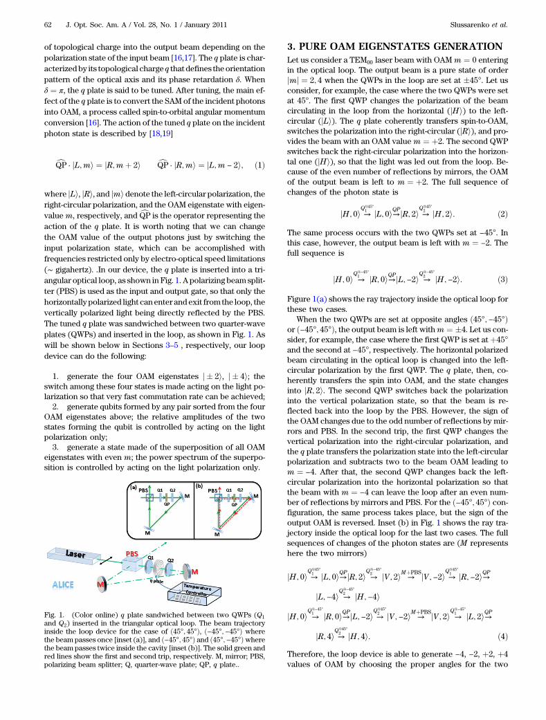
where jLi, jRi, and jmi denote the left-circular polarization, theright-circular polarization, and the OAM eigenstate with eigen-valuem, respectively, and cQP is the operator representing theaction of the q plate. It is worth noting that we can changethe OAM value of the output photons just by switching theinput polarization state, which can be accomplished withfrequencies restricted only by electro-optical speed limitations(∼ gigahertz). .In our device, the q plate is inserted into a tri-angular optical loop, as shown in Fig. 1. A polarizing beamsplit-ter (PBS) is used as the input and output gate, so that only thehorizontally polarized light canenter andexit from the loop, thevertically polarized light being directly reflected by the PBS.The tuned q plate was sandwiched between two quarter-waveplates (QWPs) and inserted in the loop, as shown in Fig. 1. Aswill be shown below in Sections 3–5 , respectively, our loopdevice can do the following:
1. generate the four OAM eigenstates j � 2i, j � 4i; theswitch among these four states is made acting on the light po-larization so that very fast commutation rate can be achieved;
2. generate qubits formed by any pair sorted from the fourOAM eigenstates above; the relative amplitudes of the twostates forming the qubit is controlled by acting on the lightpolarization only;
3. generate a state made of the superposition of all OAMeigenstates with even m; the power spectrum of the superpo-sition is controlled by acting on the light polarization only.
3. PURE OAM EIGENSTATES GENERATIONLet us consider a TEM00 laser beam with OAMm ¼ 0 enteringin the optical loop. The output beam is a pure state of orderjmj ¼ 2; 4 when the QWPs in the loop are set at �45°. Let usconsider, for example, the case where the two QWPs were setat 45°. The first QWP changes the polarization of the beamcirculating in the loop from the horizontal (jHi) to the left-circular (jLi). The q plate coherently transfers spin-to-OAM,switches the polarization into the right-circular (jRi), and pro-vides the beam with an OAM valuem ¼ þ2. The second QWPswitches back the right-circular polarization into the horizon-tal one (jHi), so that the light was led out from the loop. Be-cause of the even number of reflections by mirrors, the OAMof the output beam is left to m ¼ þ2. The full sequence ofchanges of the photon state is
jH; 0i →Q@45°1 jL; 0i→QPjR; 2i →Q
@45°2 jH; 2i: ð2Þ
The same process occurs with the two QWPs set at −45°. Inthis case, however, the output beam is left with m ¼ −2. Thefull sequence is
jH; 0i →
Q@−45°1 jR; 0i→QPjL;−2i →
Q@−45°2 jH;−2i: ð3Þ
Figure 1(a) shows the ray trajectory inside the optical loop forthese two cases.
When the two QWPs are set at opposite angles ð45°;−45°Þor ð−45°; 45°Þ, the output beam is left withm ¼ �4. Let us con-sider, for example, the case where the first QWP is set at þ45°and the second at −45°, respectively. The horizontal polarizedbeam circulating in the optical loop is changed into the left-circular polarization by the first QWP. The q plate, then, co-herently transfers the spin into OAM, and the state changesinto jR; 2i. The second QWP switches back the polarizationinto the vertical polarization state, so that the beam is re-flected back into the loop by the PBS. However, the sign ofthe OAM changes due to the odd number of reflections by mir-rors and PBS. In the second trip, the first QWP changes thevertical polarization into the right-circular polarization, andthe q plate transfers the polarization state into the left-circularpolarization and subtracts two to the beam OAM leading tom ¼ −4. After that, the second QWP changes back the left-circular polarization into the horizontal polarization so thatthe beam with m ¼ −4 can leave the loop after an even num-ber of reflections by mirrors and PBS. For the ð−45°; 45°Þ con-figuration, the same process takes place, but the sign of theoutput OAM is reversed. Inset (b) in Fig. 1 shows the ray tra-jectory inside the optical loop for the last two cases. The fullsequences of changes of the photon states are (M representshere the two mirrors)
jH; 0i →Q@45°1 jL; 0i→QPjR; 2i →
Q@−45°2 jV; 2i →
MþPBSjV;−2i →Q@45°1 jR;−2i→QP
jL;−4i →
Q@−45°2 jH;−4i
jH; 0i →
Q@−45°1 jR; 0i→QPjL;−2i →Q
@45°2 jV;−2i →
MþPBSjV; 2i →
Q@−45°1 jL; 2i→QP
jR; 4i →Q@45°2 jH; 4i: ð4Þ
Therefore, the loop device is able to generate −4, −2, þ2, þ4values of OAM by choosing the proper angles for the two
Fig. 1. (Color online) q plate sandwiched between two QWPs (Q1and Q2) inserted in the triangular optical loop. The beam trajectoryinside the loop device for the case of ð45°; 45°Þ, ð−45°;−45°Þ wherethe beam passes once [inset (a)], and ð−45°; 45°Þ and ð45°;−45°Þwherethe beam passes twice inside the cavity [inset (b)]. The solid green andred lines show the first and second trip, respectively. M, mirror; PBS,polarizing beam splitter; Q, quarter-wave plate; QP, q plate..
62 J. Opt. Soc. Am. A / Vol. 28, No. 1 / January 2011 Slussarenko et al.
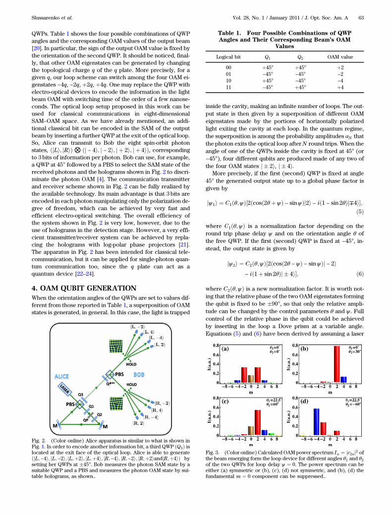
QWPs. Table 1 shows the four possible combinations of QWPangles and the corresponding OAM values of the output beam[20]. In particular, the sign of the output OAM value is fixed bythe orientation of the second QWP. It should be noticed, final-ly, that other OAM eigenstates can be generated by changingthe topological charge q of the q plate. More precisely, for agiven q, our loop scheme can switch among the four OAM ei-genstates −4q, −2q, þ2q, þ4q. One may replace the QWP withelectro-optical devices to encode the information in the lightbeam OAM with switching time of the order of a few nanose-conds. The optical loop setup proposed in this work can beused for classical communications in eight-dimensionalSAM–OAM space. As we have already mentioned, an addi-tional classical bit can be encoded in the SAM of the outputbeam by inserting a further QWP at the exit of the optical loop.So, Alice can transmit to Bob the eight spin-orbit photonstates, ðjLi; jRiÞ ⊗ ðj − 4i; j − 2i; j þ 2i; j þ 4iÞ, correspondingto 3 bits of information per photon. Bob can use, for example,a QWP at 45° followed by a PBS to select the SAM state of thereceived photons and the holograms shown in Fig. 2 to discri-minate the photon OAM [4]. The communication transmitterand receiver scheme shown in Fig. 2 can be fully realized bythe available technology. Its main advantage is that 3 bits areencoded in each photonmanipulating only the polarization de-gree of freedom, which can be achieved by very fast andefficient electro-optical switching. The overall efficiency ofthe system shown in Fig. 2 is very low, however, due to theuse of holograms in the detection stage. However, a very effi-cient transmitter/receiver system can be achieved by repla-cing the holograms with log-polar phase projectors [21].The apparatus in Fig. 2 has been intended for classical tele-communication, but it can be applied for single-photon quan-tum communication too, since the q plate can act as aquantum device [22–24].
4. OAM QUBIT GENERATIONWhen the orientation angles of the QWPs are set to values dif-ferent from those reported in Table 1, a superposition of OAMstates is generated, in general. In this case, the light is trapped
inside the cavity, making an infinite number of loops. The out-put state is then given by a superposition of different OAMeigenstates made by the portions of horizontally polarizedlight exiting the cavity at each loop. In the quantum regime,the superposition is among the probability amplitudes αN thatthe photon exits the optical loop afterN round trips. When theangle of one of the QWPs inside the cavity is fixed at 45° (or−45°), four different qubits are produced made of any two ofthe four OAM states j � 2i, j � 4i.
More precisely, if the first (second) QWP is fixed at angle45° the generated output state up to a global phase factor isgiven by
where C1ðθ;ψÞ is a normalization factor depending on theround trip phase delay ψ and on the orientation angle θ ofthe free QWP. If the first (second) QWP is fixed at −45°, in-stead, the output state is given by
where C2ðθ;ψÞ is a new normalization factor. It is worth not-ing that the relative phase of the two OAM eigenstates formingthe qubit is fixed to be �90°, so that only the relative ampli-tude can be changed by the control parameters θ and ψ . Fullcontrol of the relative phase in the qubit could be achievedby inserting in the loop a Dove prism at a variable angle.Equations (5) and (6) have been derived by assuming a laser
Fig. 2. (Color online) Alice apparatus is similar to what is shown inFig. 1. In order to encode another information bit, a third QWP ðQ3Þ islocated at the exit face of the optical loop. Alice is able to generateðjL;−4i; jL;−2i; jL;þ2i; jL;þ4i; jR;−4i; jR;−2i; jR;þ2iandjR;þ4iÞ bysetting her QWPs at �45°. Bob measures the photon SAM state by asuitable QWP and a PBS and measures the photon OAM state by sui-table holograms, as shown..
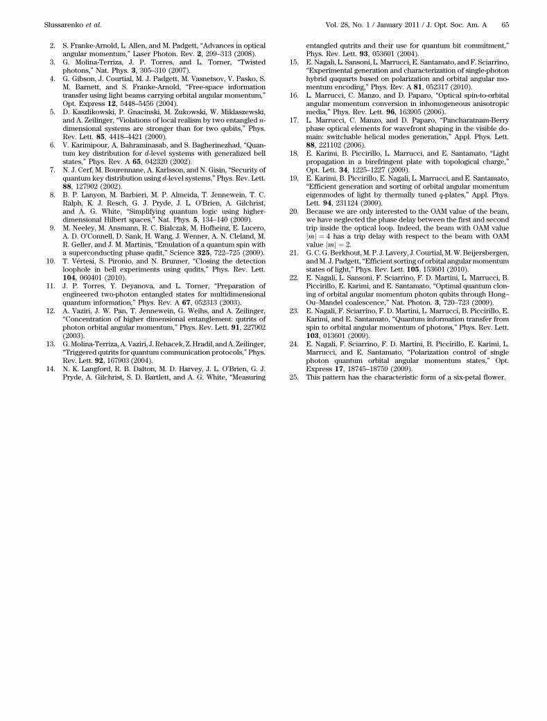
Fig. 3. (Color online) Calculated OAM power spectrum In ¼ jc2nj2 ofthe beam emerging form the loop device for different angles θ1 and θ2of the two QWPs for loop delay ψ ¼ 0. The power spectrum can beeither (a) symmetric or (b), (c), (d) not symmetric, and (b), (d) thefundamental m ¼ 0 component can be suppressed..
Slussarenko et al. Vol. 28, No. 1 / January 2011 / J. Opt. Soc. Am. A 63
coherence length much longer than the loop optical path. Thebehavior of our loop system with partially coherent light andin the single-photon regime will be the object of future study.However, we think that the possibility of exploiting the photonpolarization to control qubits formed by two OAM eigenstateswith different m may be useful for quantum computing orother quantum applications.
5. MULTIPLE OAM GENERATIONWhen both the angles of the QWPs are different from �45°, acomplex superposition of even OAM eigenstates is generated,having the general form
Pþ∞n¼−∞ c2nj2ni, where c2n depend on
the angles θ1 and θ2 of the two QWPs and on the loop delay ψ .Figure 3 shows some examples of infinite OAM state super-position obtained for different orientations θ1 and θ2 of thetwo QWPs and for ψ ¼ 0. Notice how the symmetry of theOAM power spectrum of the output beam is strongly affectedby θ1 and θ2. The odd OAM components are missing becausewe used a q ¼ 1 q plate. A full OAM spectrum can be gener-ated by using a q ¼ 1=2 q plate, but even in this case the OAMspectrum control is limited, because only a two-parametersubfamily of OAM spectra can be obtained. The possibilityof exploiting the light polarization to control full spectra of
OAM eigenstates may be useful for future, yet not identified,applications.
6. EXPERIMENTIn our first experiment, we used a cwTEM00 laser source at λ ¼532nm and measured the output beam phase front by makingan interferencewith a planelike phase front of same frequency.We used an azimuthally oriented liquid crystal homemade qplate. The optical retardation of the q plate was tuned by tem-perature controller [18] in such a way that it acted as a half-wave plate (δ ¼ π). Figure 4 shows the recorded interferencepattern of the beam exiting the optical loop for different anglesof the QWPs. The absolute value of the OAM is deduced fromthe number of prongs of the interference fork and the sign fromthe prongs up or down direction. In our second experiment, wefixed the first QWP at 45° and rotated the second one to gen-erate the qubit formed by the OAM eigenstates 2 and −4 as de-scribed before. The alignment of the loop was adjusted bymoving the two mirrors to obtain a good symmetric interfer-ence pattern [25]. For each angle θ of the secondQWP,wemea-sured the power flow associated to the m ¼ 2 and m ¼ −4components of the beam exiting the loop device by suitablecomputer-generated fork holograms displayed onto an SLM.Beyond the hologram, the m ¼ 0 component was selectedby a pinhole posed in the focal plane of a convergent lens.Finally, the measured power flows were normalized to unitymaximum value, and then the normalized power fraction car-ried by the two modes were compared with the square moduliof the coefficients in Eq. (5). The result is shown in Fig. 5. .Thefull curve is from Eq. (6). To fit the data, we used the loopretardation ψ as best fit parameter.
7. CONCLUSIONSWe presented a loop device based on a q plate to generate andencode 2 bits of information into the OAM of a single photon.The encoding process is very efficient (nominal efficiency is100%) and very fast, because it can be fully implemented byelectro-optical devices. The encoded information can be readwith a computer-generated hologram properly designed to de-tect all four OAM states simultaneously [4]. The generationprocess is deterministic, and the setup is suitable for bothclassical and quantum regimes of light. Furthermore, the op-tical loop can be easily modified to encode 3 bits of informa-tion in a single photon by adding an additional polarization bit.The same setup allows also the generation of qubits made oftwo different OAM orders or qudits with infinite number ofOAM eigenstates. The generation process of single OAM ei-genstates, OAM qubits, and OAM qudits with d ¼ ∞ is deter-ministic, has nominal 100% efficiency, and the output OAMstate can be switched by very fast electro-optical devices.
ACKNOWLEDGMENTSThe project PHORBITECH (Toolbox for Orbital AngularMomentum Technology) acknowledges the financial supportof the Future and Emerging Technologies (FET) programwithin the Seventh Framework Programme for Research ofthe European Commission, under FET-Open grant 255914..
REFERENCES AND NOTES1. A. V. Sergienko,QuantumCommunications and Cryptography
(Taylor & Francis, 2006).
Fig. 4. The interference of the output beam from the loop device andTEM00 beam for the four QWP angles shown in Table 1.
Fig. 5. (Color online) The normalized powers of the m ¼ 2 (blue)and m ¼ −4 (red) components of the loop output beam as functionsof the orientation angle θ of the second QWP. The first QWP was heldfixed at 45°. The continuous curve is the fit to the square moduli of thecoefficients of modes m ¼ 2 and m ¼ −4 in Eq. (5). The optical retar-dation ψ of the loop was used as fitting parameter. In this case , wefound a best-fit value ψ ¼ 0..
64 J. Opt. Soc. Am. A / Vol. 28, No. 1 / January 2011 Slussarenko et al.
2. S. Franke-Arnold, L. Allen, and M. Padgett, “Advances in opticalangular momentum,” Laser Photon. Rev. 2, 299–313 (2008).
3. G. Molina-Terriza, J. P. Torres, and L. Torner, “Twistedphotons,” Nat. Phys. 3, 305–310 (2007).
4. G. Gibson, J. Courtial, M. J. Padgett, M. Vasnetsov, V. Pasko, S.M. Barnett, and S. Franke-Arnold, “Free-space informationtransfer using light beams carrying orbital angular momentum,”Opt. Express 12, 5448–5456 (2004).
5. D. Kaszlikowski, P. Gnacinski, M. Zukowski, W. Miklaszewski,and A. Zeilinger, “Violations of local realism by two entangled n-dimensional systems are stronger than for two qubits,” Phys.Rev. Lett. 85, 4418–4421 (2000).
6. V. Karimipour, A. Bahraminasab, and S. Bagherinezhad, “Quan-tum key distribution for d-level systems with generalized bellstates,” Phys. Rev. A 65, 042320 (2002).
7. N. J. Cerf, M. Bourennane, A. Karlsson, and N. Gisin, “Security ofquantum key distribution using d-level systems,” Phys. Rev. Lett.88, 127902 (2002).
8. B. P. Lanyon, M. Barbieri, M. P. Almeida, T. Jennewein, T. C.Ralph, K. J. Resch, G. J. Pryde, J. L. O’Brien, A. Gilchrist,and A. G. White, “Simplifying quantum logic using higher-dimensional Hilbert spaces,” Nat. Phys. 5, 134–140 (2009).
9. M. Neeley, M. Ansmann, R. C. Bialczak, M. Hofheinz, E. Lucero,A. D. O’Connell, D. Sank, H. Wang, J. Wenner, A. N. Cleland, M.R. Geller, and J. M. Martinis, “Emulation of a quantum spin witha superconducting phase qudit,” Science 325, 722–725 (2009).
10. T. Vértesi, S. Pironio, and N. Brunner, “Closing the detectionloophole in bell experiments using qudits,” Phys. Rev. Lett.104, 060401 (2010).
11. J. P. Torres, Y. Deyanova, and L. Torner, “Preparation ofengineered two-photon entangled states for multidimensionalquantum information,” Phys. Rev. A 67, 052313 (2003).
12. A. Vaziri, J. W. Pan, T. Jennewein, G. Weihs, and A. Zeilinger,“Concentration of higher dimensional entanglement: qutrits ofphoton orbital angular momentum,” Phys. Rev. Lett. 91, 227902(2003).
13. G.Molina-Terriza,A.Vaziri, J.Rehacek,Z.Hradil, andA.Zeilinger,“Triggered qutrits for quantum communication protocols,” Phys.Rev. Lett. 92, 167903 (2004).
14. N. K. Langford, R. B. Dalton, M. D. Harvey, J. L. O’Brien, G. J.Pryde, A. Gilchrist, S. D. Bartlett, and A. G. White, “Measuring
entangled qutrits and their use for quantum bit commitment,”Phys. Rev. Lett. 93, 053601 (2004).
15. E. Nagali, L. Sansoni, L. Marrucci, E. Santamato, andF. Sciarrino,“Experimental generation and characterization of single-photonhybrid ququarts based on polarization and orbital angular mo-mentum encoding,” Phys. Rev. A 81, 052317 (2010).
16. L. Marrucci, C. Manzo, and D. Paparo, “Optical spin-to-orbitalangular momentum conversion in inhomogeneous anisotropicmedia,” Phys. Rev. Lett. 96, 163905 (2006).
17. L. Marrucci, C. Manzo, and D. Paparo, “Pancharatnam-Berryphase optical elements for wavefront shaping in the visible do-main: switchable helical modes generation,” Appl. Phys. Lett.88, 221102 (2006).
18. E. Karimi, B. Piccirillo, L. Marrucci, and E. Santamato, “Lightpropagation in a birefringent plate with topological charge,”Opt. Lett. 34, 1225–1227 (2009).
19. E. Karimi, B. Piccirillo, E. Nagali, L. Marrucci, and E. Santamato,“Efficient generation and sorting of orbital angular momentumeigenmodes of light by thermally tuned q-plates,” Appl. Phys.Lett. 94, 231124 (2009).
20. Because we are only interested to the OAM value of the beam,we have neglected the phase delay between the first and secondtrip inside the optical loop. Indeed, the beam with OAM valuejmj ¼ 4 has a trip delay with respect to the beam with OAMvalue jmj ¼ 2.
21. G.C.G.Berkhout,M.P. J. Lavery, J.Courtial,M.W.Beijersbergen,andM. J. Padgett, “Efficient sorting of orbital angularmomentumstates of light,” Phys. Rev. Lett. 105, 153601 (2010).
22. E. Nagali, L. Sansoni, F. Sciarrino, F. D. Martini, L. Marrucci, B.Piccirillo, E. Karimi, and E. Santamato, “Optimal quantum clon-ing of orbital angular momentum photon qubits through Hong–Ou–Mandel coalescence,” Nat. Photon. 3, 720–723 (2009).
23. E. Nagali, F. Sciarrino, F. D. Martini, L. Marrucci, B. Piccirillo, E.Karimi, and E. Santamato, “Quantum information transfer fromspin to orbital angular momentum of photons,” Phys. Rev. Lett.103, 013601 (2009).
24. E. Nagali, F. Sciarrino, F. D. Martini, B. Piccirillo, E. Karimi, L.Marrucci, and E. Santamato, “Polarization control of singlephoton quantum orbital angular momentum states,” Opt.Express 17, 18745–18759 (2009).
25. This pattern has the characteristic form of a six-petal flower.
Slussarenko et al. Vol. 28, No. 1 / January 2011 / J. Opt. Soc. Am. A 65