Published in IET Communications Received on 9th April 2012 Revised on 6th October 2012 Accepted on 3rd November 2012 doi: 10.1049/iet-com.2012.0188 ISSN 1751-8628 Efficient narrowband interference cancellation in ultra-wide-band rake receivers Omid Abedi, Mustapha C.E. Yagoub School of Electrical Engineering and Computer Science, University of Ottawa, Ottawa, ON K1N6N5, Canada E-mail: [email protected]Abstract: In this study, different pulse modulation parameters, such as symbol error rate (SER), power loss and bandwidth were investigated to highlight the most suitable parameter for narrowband interference cancellation in ultra-wide-band (UWB) Rake receivers. Thus, the performance of transmitter pulse was evaluated at the UWB Rake receiver. Finally, comparison of various filter bank receivers in terms of number of filters and SER was achieved by using a new accurate indoor UWB IEEE model channel with different propagation scenarios. 1 Introduction Ultra-wide-band (UWB) systems have been extensively studied in the recent few years because of their wide potential applications, particularly in short-range access wireless communication. However, some key UWB receiver parameters, such as narrowband interference (NBI), still need more investigation for optimum performance, especially in the presence of colour noise. In fact, NBI plays a crucial role in UWB receiver performance since it reduces the receiver signal-to-noise ratio (SNR), thus directly affecting the probability of error and consequently, the system capacity [1]. Although UWB pulses propagating through obstacles can be scattered, creating multipath pulses that remove energy from the primary pulse, UWB technology allows separation of the direct pulse [2, 3]. One of the solutions for increasing the receiver SNR is to use a Rake receiver, which takes the advantage of UWB selective frequency fading to combine energy from multipath pulses. However, in case of extreme non-line-of-sight (ENLOS) and channel delay, the Rake receiver requires more correlators, thus leading to higher circuit complexity [4]. An ideal Rake receiver (IRake), expected to capture all multipath energy, can be used as reference; however, partial Rake (PRake) [5] or selective Rake (SRake) receivers are more suitable and practical [6]. In this paper, a simple PRake receiver structure is proposed to reduce circuit complexity. It combines the number of partial paths (LP) and the first arrival path out of the total multipath (LI) components [7, 8]. To reach such a target, we analysed the performance of PRake while optimising the number of fingers of the filter bank, its stepped impedance resonator (SIR) and the symbol error rate (SER) [7]. We also assumed a causal, statistical channel including interference noise (colour noise), tones and narrowband noise. In terms of pulse modulation, because of its smooth power spectrum density (PSD), limited number of discrete components and relatively low noise sensitivity, SER and power consumption, the 4-pulse position modulation (4-PPM) was retained, along with the fifth derivative of a Gaussian pulse as pulse shape [1, 2]. We also introduced a modified indoor UWB IEEE channel model [9, 10], which considers statistical path loss for ENLOS and the effects of pulse shape and distribution in different environments to efficiently predict the overall performance of UWB systems. 2 Proposed indoor UWB channel model Accurate channel characterisation allows correct evaluation of key parameters like frequency spectrum and transmitted power [11, 12]. In narrowband systems, multipath propagation leads to multipath fading, whereas in UWB systems, monocycles commonly do not overlap because the pulse width is smaller than the channel propagation delay. However, only limited work has been achieved on UWB channel modelling [13]. Parameters to be involved in such models include signal characteristics, delay distribution and pulse shape distortion distribution [14]. 2.1 IEEE 802.15.3a UWB indoor channel model Several works have been carried out to model indoor/outdoor LOS/NLOS scenarios [15, 16]. However, in case of extremely NLOS environments (ENLOS), the above parameters have to be carefully evaluated. Therefore we introduced a modified expression for the impulse response in an IEEE 802.15.3a UWB indoor channel model as h(t )= G N n=1 K k =1 a nk d(t − T n − t nk ) (1) www.ietdl.org IET Commun., 2013, Vol. 7, Iss. 1, pp. 57–64 57 doi: 10.1049/iet-com.2012.0188 & The Institution of Engineering and Technology 2013
Transcript
Published in IET CommunicationsReceived on 9th April 2012Revised on 6th October 2012Accepted on 3rd November 2012doi: 10.1049/iet-com.2012.0188
Abstract: In this study, different pulse modulation parameters, such as symbol error rate (SER), power loss and bandwidth wereinvestigated to highlight the most suitable parameter for narrowband interference cancellation in ultra-wide-band (UWB) Rakereceivers. Thus, the performance of transmitter pulse was evaluated at the UWB Rake receiver. Finally, comparison ofvarious filter bank receivers in terms of number of filters and SER was achieved by using a new accurate indoor UWB IEEEmodel channel with different propagation scenarios.
1 Introduction
Ultra-wide-band (UWB) systems have been extensivelystudied in the recent few years because of their widepotential applications, particularly in short-range accesswireless communication. However, some key UWB receiverparameters, such as narrowband interference (NBI), stillneed more investigation for optimum performance,especially in the presence of colour noise. In fact, NBIplays a crucial role in UWB receiver performance since itreduces the receiver signal-to-noise ratio (SNR), thusdirectly affecting the probability of error and consequently,the system capacity [1].Although UWB pulses propagating through obstacles can
be scattered, creating multipath pulses that remove energyfrom the primary pulse, UWB technology allows separationof the direct pulse [2, 3]. One of the solutions forincreasing the receiver SNR is to use a Rake receiver,which takes the advantage of UWB selective frequencyfading to combine energy from multipath pulses. However,in case of extreme non-line-of-sight (ENLOS) and channeldelay, the Rake receiver requires more correlators, thusleading to higher circuit complexity [4]. An ideal Rakereceiver (IRake), expected to capture all multipath energy,can be used as reference; however, partial Rake (PRake) [5]or selective Rake (SRake) receivers are more suitable andpractical [6].In this paper, a simple PRake receiver structure is proposed
to reduce circuit complexity. It combines the number ofpartial paths (LP) and the first arrival path out of the totalmultipath (LI) components [7, 8]. To reach such a target,we analysed the performance of PRake while optimising thenumber of fingers of the filter bank, its stepped impedanceresonator (SIR) and the symbol error rate (SER) [7]. Wealso assumed a causal, statistical channel includinginterference noise (colour noise), tones and narrowbandnoise.
IET Commun., 2013, Vol. 7, Iss. 1, pp. 57–64doi: 10.1049/iet-com.2012.0188
In terms of pulse modulation, because of its smooth powerspectrum density (PSD), limited number of discretecomponents and relatively low noise sensitivity, SER andpower consumption, the 4-pulse position modulation(4-PPM) was retained, along with the fifth derivative of aGaussian pulse as pulse shape [1, 2]. We also introduced amodified indoor UWB IEEE channel model [9, 10], whichconsiders statistical path loss for ENLOS and the effects ofpulse shape and distribution in different environments toefficiently predict the overall performance of UWB systems.
2 Proposed indoor UWB channel model
Accurate channel characterisation allows correct evaluation ofkey parameters like frequency spectrum and transmittedpower [11, 12]. In narrowband systems, multipathpropagation leads to multipath fading, whereas in UWBsystems, monocycles commonly do not overlap because thepulse width is smaller than the channel propagation delay.However, only limited work has been achieved on UWBchannel modelling [13]. Parameters to be involved in suchmodels include signal characteristics, delay distribution andpulse shape distortion distribution [14].
2.1 IEEE 802.15.3a UWB indoor channel model
Several works have been carried out to model indoor/outdoorLOS/NLOS scenarios [15, 16]. However, in case of extremelyNLOS environments (ENLOS), the above parameters have tobe carefully evaluated. Therefore we introduced a modifiedexpression for the impulse response in an IEEE 802.15.3aUWB indoor channel model as
h(t) = G∑Nn=1
∑Kk=1
ankd(t − Tn − tnk) (1)
57& The Institution of Engineering and Technology 2013
www.ietdl.org
where G is a log-normal random variable representing themagnitude of the channel gain; N is the number of clustersand K the number of multi-paths for a particular cluster.ank = bnke
−unk is the number of multi-path complexrandom variables per cluster, βnk is a statisticallyindependent random variable with Raleigh distribution, andθnk a statistically independent random variable with uniformdistribution representing the pulse multi-path inversion. Tnis the time arrival for nth cluster and τnk the multi-pathdelay, for a particular cluster distribution.Thus, the average cluster delay can be defined as
trms =
���������������������������������∑Nn=1
t2na2n/G −
∑Nn=1
tna2n/G
( )2√√√√ (2)
The proposed expression covers not only the pulse amplitudedistortion per cluster but also the pulse shape/phase distortionas well. However, the above IEEE model assumes that allchannel parameters are time-dependent. This generalapproach is accurate but not practical, especially for indoorchannels. We have then to propose a simpler model whichcan significantly reduce the simulation time.
2.2 Random channel
The proposed random channel impulse response can beexpressed as [17]
h(t) =∑Nn=1
and t − n tn( ) (3)
In this equation, there is no assumption for pulse shapedistortion or channel propagation. Therefore it presents amajor drawback when applied to impulse ratio techniquesand does not account for pulse shape variation because ofreflection or penetrations through material. Also, the angleof pulse arrival distribution is neglected, the gainattenuation distribution is uniform and the attenuation decayhas the same rate, implying low complexity receiver designand thus, a higher probability of error. Note that thissimplicity was not achieved at the expense of accuracy.This point will be validated in Section 6.
3 UWB noise modelling
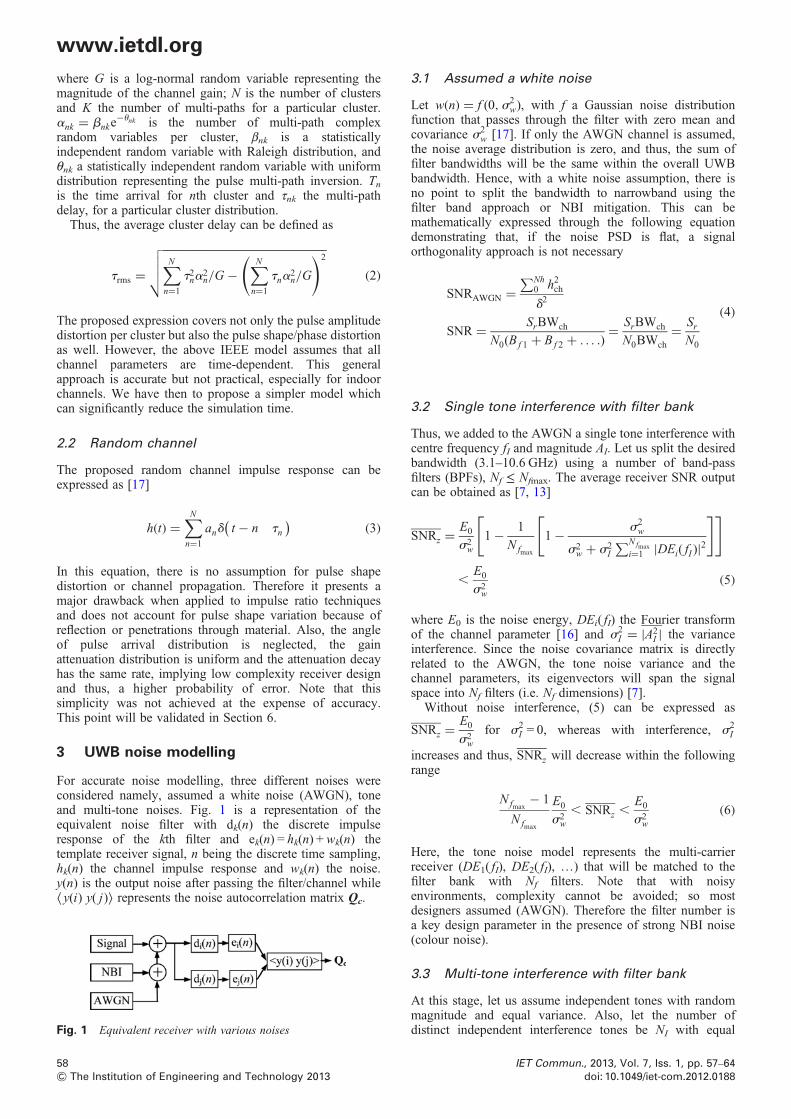
For accurate noise modelling, three different noises wereconsidered namely, assumed a white noise (AWGN), toneand multi-tone noises. Fig. 1 is a representation of theequivalent noise filter with dk(n) the discrete impulseresponse of the kth filter and ek(n) = hk(n) +wk(n) thetemplate receiver signal, n being the discrete time sampling,hk(n) the channel impulse response and wk(n) the noise.y(n) is the output noise after passing the filter/channel while⟨y(i) y( j)⟩ represents the noise autocorrelation matrix Qc.
Fig. 1 Equivalent receiver with various noises
58& The Institution of Engineering and Technology 2013
3.1 Assumed a white noise
Let w(n) = f (0,s2w), with f a Gaussian noise distribution
function that passes through the filter with zero mean andcovariance s2
w [17]. If only the AWGN channel is assumed,the noise average distribution is zero, and thus, the sum offilter bandwidths will be the same within the overall UWBbandwidth. Hence, with a white noise assumption, there isno point to split the bandwidth to narrowband using thefilter band approach or NBI mitigation. This can bemathematically expressed through the following equationdemonstrating that, if the noise PSD is flat, a signalorthogonality approach is not necessary
SNRAWGN =∑Nh
0 h2chd2
SNR = SrBWch
N0(Bf 1 + Bf 2 + . . . .)= SrBWch
N0BWch
= SrN0
(4)
3.2 Single tone interference with filter bank
Thus, we added to the AWGN a single tone interference withcentre frequency fI and magnitude AI. Let us split the desiredbandwidth (3.1–10.6 GHz) using a number of band-passfilters (BPFs), Nf ≤ Nfmax. The average receiver SNR outputcan be obtained as [7, 13]
SNRz =E0
s2w
1− 1
Nfmax
1− s2w
s2w + s2
I
∑N fmax
i=1 |DEi( fI )|2
[ ][ ]
,E0
s2w
(5)
where E0 is the noise energy, DEi( fI) the Fourier transformof the channel parameter [16] and s2
I = |A2I | the variance
interference. Since the noise covariance matrix is directlyrelated to the AWGN, the tone noise variance and thechannel parameters, its eigenvectors will span the signalspace into Nf filters (i.e. Nf dimensions) [7].Without noise interference, (5) can be expressed as
SNRz =E0
s2w
for s2I = 0, whereas with interference, s2
I
increases and thus, SNRz will decrease within the followingrange
Nfmax− 1
Nfmax
E0
s2w, SNRz ,
E0
s2w
(6)
Here, the tone noise model represents the multi-carrierreceiver (DE1( fI), DE2( fI), …) that will be matched to thefilter bank with Nf filters. Note that with noisyenvironments, complexity cannot be avoided; so mostdesigners assumed (AWGN). Therefore the filter number isa key design parameter in the presence of strong NBI noise(colour noise).
3.3 Multi-tone interference with filter bank
At this stage, let us assume independent tones with randommagnitude and equal variance. Also, let the number ofdistinct independent interference tones be NI with equal
IET Commun., 2013, Vol. 7, Iss. 1, pp. 57–64doi: 10.1049/iet-com.2012.0188
www.ietdl.org
variance. The average output SNR can be thus obtained as[13]
kSNRZl =E0
s2w
Nf − NI
Nf
+ E0
Nf
∑NI
i=1
1
s2w + s2
i
∑Nf
k=1 |DEk( fI )|(7)
Nf − NI
Nf
E0
s2w, kSNRZl ,
E0
s2w
(8)
It is clear that compared with a single tone, multi-tone SNR isworse since it is reduced by a factor of {−10 log [(Nf −NI)/Nf]}. Hence, the solution will be to increase Nf.Investigations demonstrated that an optimal correlator canbe set to Nfmax = 10 for which the BER is very low.Therefore an optimal filter number of 10 will make theinterference noise negligible.
4 Theory and performance of various Rakereceivers
A received multi-path signal r(t) consists of the superpositionof several attenuated, delayed and eventually distortedreplicas of a transmitted waveform [1]. There are differentstrategies for exploiting diversity that can be adopted suchas selection diversity, equal gain combining and maximalratio combining (MRC) methods [18]. In MRC, thedifferent contributions are weighted and the weights aredetermined to maximise the SNR before the decisionprocesses. Also, note that if the channel is assumed flat inthe LOS case, the pulse period th will be less than thechannel delay and thus, multi-path weighting techniquessuch as GMF are not necessary [7].The optimal receiver matched to a single waveform
corresponds to the first correlator. In the Rake receiver case,the optimum correlator must include additional correlatorsassociated with different replicas of the transmittedwaveform [19, 20].The Rake receiver performance was then evaluated
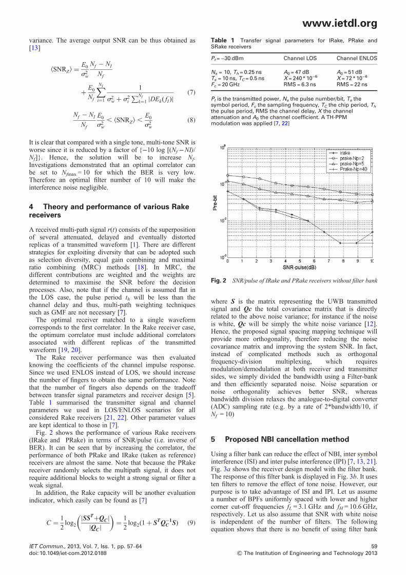
knowing the coefficients of the channel impulse response.Since we used ENLOS instead of LOS, we should increasethe number of fingers to obtain the same performance. Notethat the number of fingers also depends on the tradeoffbetween transfer signal parameters and receiver design [5].Table 1 summarised the transmitter signal and channelparameters we used in LOS/ENLOS scenarios for allconsidered Rake receivers [21, 22]. Other parameter valuesare kept identical to those in [7].Fig. 2 shows the performance of various Rake receivers
(IRake and PRake) in terms of SNR/pulse (i.e. inverse ofBER). It can be seen that by increasing the correlator, theperformance of both PRake and IRake (taken as reference)receivers are almost the same. Note that because the PRakereceiver randomly selects the multipath signal, it does notrequire additional blocks to weight a strong signal or filter aweak signal.In addition, the Rake capacity will be another evaluation
indicator, which easily can be found as [7]
C = 1
2log2
|SST+QC||QC|
( )= 1
2log2(1+ STQ−1
C S) (9)
IET Commun., 2013, Vol. 7, Iss. 1, pp. 57–64doi: 10.1049/iet-com.2012.0188
where S is the matrix representing the UWB transmittedsignal and Qc the total covariance matrix that is directlyrelated to the above noise variance; for instance if the noiseis white, Qc will be simply the white noise variance [12].Hence, the proposed signal spacing mapping technique willprovide more orthogonality, therefore reducing the noisecovariance matrix and improving the system SNR. In fact,instead of complicated methods such as orthogonalfrequency-division multiplexing, which requiresmodulation/demodulation at both receiver and transmittersides, we simply divided the bandwidth using a Filter-bankand then efficiently separated noise. Noise separation ornoise orthogonality achieves better SNR, whereasbandwidth division relaxes the analogue-to-digital converter(ADC) sampling rate (e.g. by a rate of 2*bandwidth/10, ifNf = 10)
5 Proposed NBI cancellation method
Using a filter bank can reduce the effect of NBI, inter symbolinterference (ISI) and inter pulse interference (IPI) [7, 13, 21].Fig. 3a shows the receiver design model with the filter bank.The response of this filter bank is displayed in Fig. 3b. It usesten filters to remove the effect of tone noise. However, ourpurpose is to take advantage of ISI and IPI. Let us assumea number of BPFs uniformly spaced with lower and highercorner cut-off frequencies fL = 3.1 GHz and fH = 10.6 GHz,respectively. Let us also assume that SNR with white noiseis independent of the number of filters. The followingequation shows that there is no benefit of using filter bank
Fig. 2 SNR/pulse of IRake and PRake receivers without filter bank
Table 1 Transfer signal parameters for IRake, PRake andSRake receivers
Pt =−30 dBm Channel LOS Channel ENLOS
Ns = 10, Th = 0.25 ns A0 = 47 dB A0 = 51 dBTs = 10 ns, TC = 0.5 ns X = 240*10−6 X = 72*10−6
Fc = 20GHz RMS= 6.3 ns RMS= 22 ns
Pt is the transmitted power, Ns the pulse number/bit, Ts thesymbol period, Fc the sampling frequency, TC the chip period, Th
the pulse period, RMS the channel delay, X the channelattenuation and A0 the channel coefficient. A TH-PPMmodulation was applied [7, 22]
59& The Institution of Engineering and Technology 2013
www.ietdl.org
Fig. 3 Receiver design model with the filter bank and the response of this filter bank is displayed
a Receiver with the filter bank diagram (from [13])b Second-order Butterworth filter with ten filters
if the noise is assumed white [7]
SNRAWGN =∑Nh
0 h2ch∫B fn
B f1
(PSDAWGN)df︸����������︷︷����������︸N0
SNR = SrBWch
N0(Bf 1 + Bf 2 + . . . .)= SrBWch
N0BWch
= SrN0
(10)
with hch the channel impulse response, Sr the receiver signal,BWch the desired bandwidth and No the noise power. Bfn
is thebandwidth of the nth BPF filter. By adding the tone noise, thescenario becomes different. In fact, even with only two filters,the capacity and BER become strongly dependent on theinterference because of leakage of the second filter(Fig. 4b). As illustrated in Fig. 4a, the BER is improved byapplying a filter bank. This is due to the dimensionality ofthe noise subspace being reduced to a single dimension,while the filter bank is dependent on the number of filters(FN).
5.1 Filter bank specifications
The second order biquad section is modelled with qualityfactor Q and centre frequency wc [7]
60& The Institution of Engineering and Technology 2013
H(s) = (wc/Q)ss2 + (wc/Q)s+ wc2
Q =�������1− B
B
√Awc
|wc2 − A2|A = wc+ pB fn
B = (wc/Q)A−A2 + j(wc/Q)A+ wc2
∣∣∣∣∣∣∣∣2
= ((wc/Q)A)2(wc2 − A2)2 + (wc2A2)/Q2
(11)
Note that the energy per channel filter can be expressed as
Echj =∑length(hch)
i=1
|hchj i|2 (12)
This energy varies significantly for each channel impulseresponse hch(n) that is randomly determined. The signaloutputs have to be generated for each band-pass filter. Ineach case, we correlated the output of each filter with thematched filter weights applied to the correlator followingeach of the BPFs in a Rake receiver. The outputs of the Nf
Rakes are then combined according to the GMF weightingalgorithm [18]. The weighting coefficients are determinedby W= Q−1
C S and the related noise covariance matrix is
Fig. 4 BER comparison without filter bank and capacity for various filter numbers
a BER comparison without filter bank and for various filter numbers (low receiver SNR)b Capacity for various filter numbers (low receiver SNR)
IET Commun., 2013, Vol. 7, Iss. 1, pp. 57–64doi: 10.1049/iet-com.2012.0188
www.ietdl.org
defined by
QCij= k(hei∗w)(hej∗w)l
QCij= kyiyjl=
∑1k=0
∑1k′=0
hei (t)hej (t′)Rw(t − t′)
(13)
Here, Rw is the autocorrelation of the IRake weightingcoefficients. Finally, the SNR output decision variable wascalculated using the model shown in Fig. 3a
s2Z = kZ2l− kZl2 = STQ−1
C S, SNRZ = STQ−1C S (14)
With low receiver SNR, Fig. 4a shows a BER comparisonwithout filter bank and for various filter numbers, whileFig. 4b shows the capacity performance against the filternumber. As illustrated, by using filter banks, both BER andcapacity have been improved even with strong interference.It also shows that with higher SIR (lower interference), theperformance with a lower number of filters number issimilar to that with a higher number. Therefore a maximumnumber can be practically set as Nfmax
, 6.
5.2 Channel estimation
Note that we assumed that the proposed channel model isstationary since the channel variable rate is much smallerthan the pulse rate. In case of ENLOS, the effect of the
IET Commun., 2013, Vol. 7, Iss. 1, pp. 57–64doi: 10.1049/iet-com.2012.0188
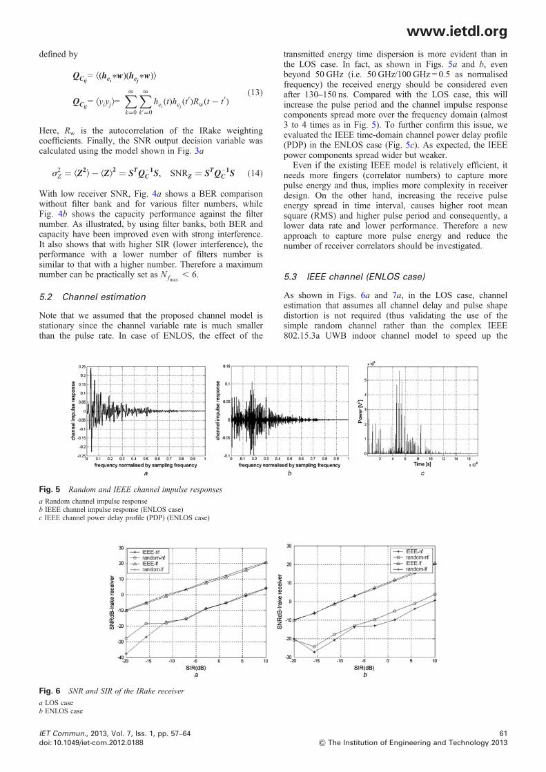
transmitted energy time dispersion is more evident than inthe LOS case. In fact, as shown in Figs. 5a and b, evenbeyond 50 GHz (i.e. 50 GHz/100 GHz = 0.5 as normalisedfrequency) the received energy should be considered evenafter 130–150 ns. Compared with the LOS case, this willincrease the pulse period and the channel impulse responsecomponents spread more over the frequency domain (almost3 to 4 times as in Fig. 5). To further confirm this issue, weevaluated the IEEE time-domain channel power delay profile(PDP) in the ENLOS case (Fig. 5c). As expected, the IEEEpower components spread wider but weaker.Even if the existing IEEE model is relatively efficient, it
needs more fingers (correlator numbers) to capture morepulse energy and thus, implies more complexity in receiverdesign. On the other hand, increasing the receive pulseenergy spread in time interval, causes higher root meansquare (RMS) and higher pulse period and consequently, alower data rate and lower performance. Therefore a newapproach to capture more pulse energy and reduce thenumber of receiver correlators should be investigated.
5.3 IEEE channel (ENLOS case)
As shown in Figs. 6a and 7a, in the LOS case, channelestimation that assumes all channel delay and pulse shapedistortion is not required (thus validating the use of thesimple random channel rather than the complex IEEE802.15.3a UWB indoor channel model to speed up the
Fig. 5 Random and IEEE channel impulse responses
a Random channel impulse responseb IEEE channel impulse response (ENLOS case)c IEEE channel power delay profile (PDP) (ENLOS case)
Fig. 6 SNR and SIR of the IRake receiver
a LOS caseb ENLOS case
61& The Institution of Engineering and Technology 2013
www.ietdl.org
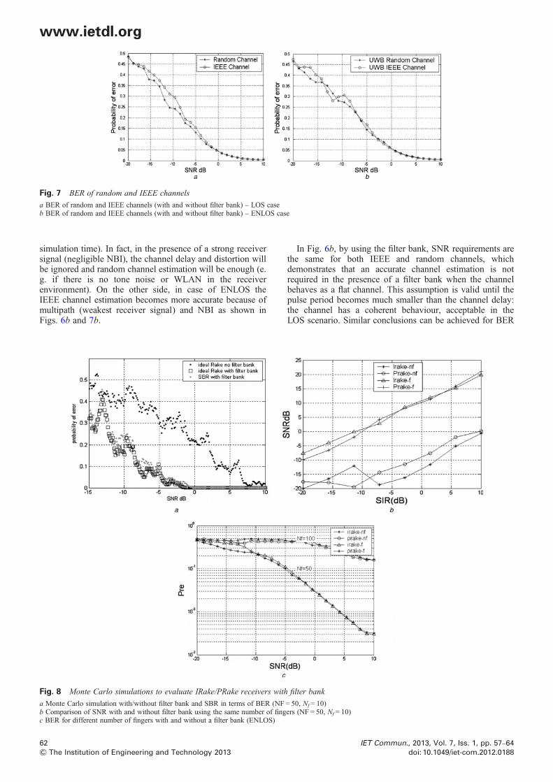
Fig. 7 BER of random and IEEE channels
a BER of random and IEEE channels (with and without filter bank) – LOS caseb BER of random and IEEE channels (with and without filter bank) – ENLOS case
simulation time). In fact, in the presence of a strong receiversignal (negligible NBI), the channel delay and distortion willbe ignored and random channel estimation will be enough (e.g. if there is no tone noise or WLAN in the receiverenvironment). On the other side, in case of ENLOS theIEEE channel estimation becomes more accurate because ofmultipath (weakest receiver signal) and NBI as shown inFigs. 6b and 7b.
62& The Institution of Engineering and Technology 2013
In Fig. 6b, by using the filter bank, SNR requirements arethe same for both IEEE and random channels, whichdemonstrates that an accurate channel estimation is notrequired in the presence of a filter bank when the channelbehaves as a flat channel. This assumption is valid until thepulse period becomes much smaller than the channel delay:the channel has a coherent behaviour, acceptable in theLOS scenario. Similar conclusions can be achieved for BER
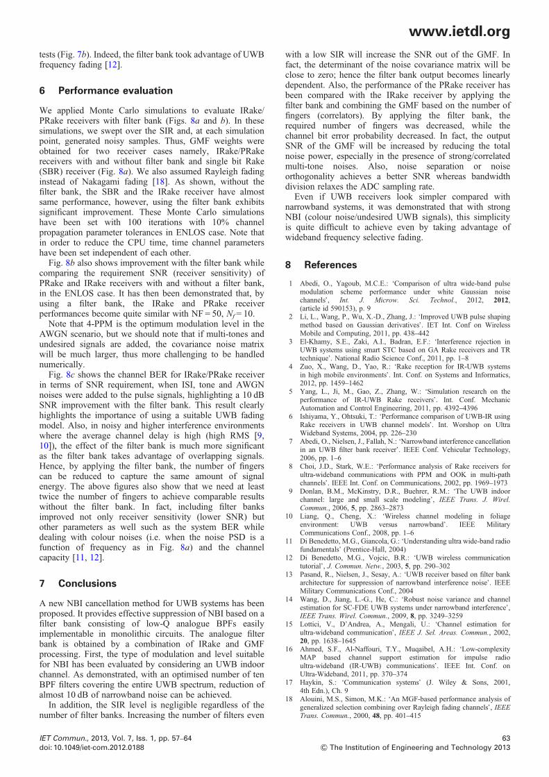
Fig. 8 Monte Carlo simulations to evaluate IRake/PRake receivers with filter bank
a Monte Carlo simulation with/without filter bank and SBR in terms of BER (NF = 50, Nf = 10)b Comparison of SNR with and without filter bank using the same number of fingers (NF = 50, Nf = 10)c BER for different number of fingers with and without a filter bank (ENLOS)
IET Commun., 2013, Vol. 7, Iss. 1, pp. 57–64doi: 10.1049/iet-com.2012.0188
www.ietdl.org
tests (Fig. 7b). Indeed, the filter bank took advantage of UWBfrequency fading [12].
6 Performance evaluation
We applied Monte Carlo simulations to evaluate IRake/PRake receivers with filter bank (Figs. 8a and b). In thesesimulations, we swept over the SIR and, at each simulationpoint, generated noisy samples. Thus, GMF weights wereobtained for two receiver cases namely, IRake/PRakereceivers with and without filter bank and single bit Rake(SBR) receiver (Fig. 8a). We also assumed Rayleigh fadinginstead of Nakagami fading [18]. As shown, without thefilter bank, the SBR and the IRake receiver have almostsame performance, however, using the filter bank exhibitssignificant improvement. These Monte Carlo simulationshave been set with 100 iterations with 10% channelpropagation parameter tolerances in ENLOS case. Note thatin order to reduce the CPU time, time channel parametershave been set independent of each other.Fig. 8b also shows improvement with the filter bank while
comparing the requirement SNR (receiver sensitivity) ofPRake and IRake receivers with and without a filter bank,in the ENLOS case. It has then been demonstrated that, byusing a filter bank, the IRake and PRake receiverperformances become quite similar with NF = 50, Nf = 10.Note that 4-PPM is the optimum modulation level in the
AWGN scenario, but we should note that if multi-tones andundesired signals are added, the covariance noise matrixwill be much larger, thus more challenging to be handlednumerically.Fig. 8c shows the channel BER for IRake/PRake receiver
in terms of SNR requirement, when ISI, tone and AWGNnoises were added to the pulse signals, highlighting a 10 dBSNR improvement with the filter bank. This result clearlyhighlights the importance of using a suitable UWB fadingmodel. Also, in noisy and higher interference environmentswhere the average channel delay is high (high RMS [9,10]), the effect of the filter bank is much more significantas the filter bank takes advantage of overlapping signals.Hence, by applying the filter bank, the number of fingerscan be reduced to capture the same amount of signalenergy. The above figures also show that we need at leasttwice the number of fingers to achieve comparable resultswithout the filter bank. In fact, including filter banksimproved not only receiver sensitivity (lower SNR) butother parameters as well such as the system BER whiledealing with colour noises (i.e. when the noise PSD is afunction of frequency as in Fig. 8a) and the channelcapacity [11, 12].
7 Conclusions
A new NBI cancellation method for UWB systems has beenproposed. It provides effective suppression of NBI based on afilter bank consisting of low-Q analogue BPFs easilyimplementable in monolithic circuits. The analogue filterbank is obtained by a combination of IRake and GMFprocessing. First, the type of modulation and level suitablefor NBI has been evaluated by considering an UWB indoorchannel. As demonstrated, with an optimised number of tenBPF filters covering the entire UWB spectrum, reduction ofalmost 10 dB of narrowband noise can be achieved.In addition, the SIR level is negligible regardless of the
number of filter banks. Increasing the number of filters even
IET Commun., 2013, Vol. 7, Iss. 1, pp. 57–64doi: 10.1049/iet-com.2012.0188
with a low SIR will increase the SNR out of the GMF. Infact, the determinant of the noise covariance matrix will beclose to zero; hence the filter bank output becomes linearlydependent. Also, the performance of the PRake receiver hasbeen compared with the IRake receiver by applying thefilter bank and combining the GMF based on the number offingers (correlators). By applying the filter bank, therequired number of fingers was decreased, while thechannel bit error probability decreased. In fact, the outputSNR of the GMF will be increased by reducing the totalnoise power, especially in the presence of strong/correlatedmulti-tone noises. Also, noise separation or noiseorthogonality achieves a better SNR whereas bandwidthdivision relaxes the ADC sampling rate.Even if UWB receivers look simpler compared with
narrowband systems, it was demonstrated that with strongNBI (colour noise/undesired UWB signals), this simplicityis quite difficult to achieve even by taking advantage ofwideband frequency selective fading.
8 References
1 Abedi, O., Yagoub, M.C.E.: ‘Comparison of ultra wide-band pulsemodulation scheme performance under white Gaussian noisechannels’, Int. J. Microw. Sci. Technol., 2012, 2012,(article id 590153), p. 9
2 Li, L., Wang, P., Wu, X.-D., Zhang, J.: ‘Improved UWB pulse shapingmethod based on Gaussian derivatives’. IET Int. Conf on WirelessMobile and Computing, 2011, pp. 438–442
3 El-Khamy, S.E., Zaki, A.I., Badran, E.F.: ‘Interference rejection inUWB systems using smart STC based on GA Rake receivers and TRtechnique’. National Radio Science Conf., 2011, pp. 1–8
4 Zuo, X., Wang, D., Yao, R.: ‘Rake reception for IR-UWB systemsin high mobile environments’. Int. Conf. on Systems and Informatics,2012, pp. 1459–1462
5 Yang, L., Ji, M., Gao, Z., Zhang, W.: ‘Simulation research on theperformance of IR-UWB Rake receivers’. Int. Conf. MechanicAutomation and Control Engineering, 2011, pp. 4392–4396
6 Ishiyama, Y., Ohtsuki, T.: ‘Performance comparison of UWB-IR usingRake receivers in UWB channel models’. Int. Worshop on UltraWideband Systems, 2004, pp. 226–230
7 Abedi, O., Nielsen, J., Fallah, N.: ‘Narrowband interference cancellationin an UWB filter bank receiver’. IEEE Conf. Vehicular Technology,2006, pp. 1–6
8 Choi, J.D., Stark, W.E.: ‘Performance analysis of Rake receivers forultra-wideband communications with PPM and OOK in multi-pathchannels’. IEEE Int. Conf. on Communications, 2002, pp. 1969–1973
9 Donlan, B.M., McKinstry, D.R., Buehrer, R.M.: ‘The UWB indoorchannel: large and small scale modeling’, IEEE Trans. J. Wirel.Commun., 2006, 5, pp. 2863–2873
10 Liang, Q., Cheng, X.: ‘Wireless channel modeling in foliageenvironment: UWB versus narrowband’. IEEE MilitaryCommunications Conf., 2008, pp. 1–6
12 Di Benedetto, M.G., Vojcic, B.R.: ‘UWB wireless communicationtutorial’, J. Commun. Netw., 2003, 5, pp. 290–302
13 Pasand, R., Nielsen, J., Sesay, A.: ‘UWB receiver based on filter bankarchitecture for suppression of narrowband interference noise’. IEEEMilitary Communications Conf., 2004
14 Wang, D., Jiang, L.-G., He, C.: ‘Robust noise variance and channelestimation for SC-FDE UWB systems under narrowband interference’,IEEE Trans. Wirel. Commun., 2009, 8, pp. 3249–3259
15 Lottici, V., D’Andrea, A., Mengali, U.: ‘Channel estimation forultra-wideband communication’, IEEE J. Sel. Areas. Commun., 2002,20, pp. 1638–1645
16 Ahmed, S.F., Al-Naffouri, T.Y., Muqaibel, A.H.: ‘Low-complexityMAP based channel support estimation for impulse radioultra-wideband (IR-UWB) communications’. IEEE Int. Conf. onUltra-Wideband, 2011, pp. 370–374
with imperfect tap weights’. Int. Conf. on Acoustics, Speech, andSignal Processing, 2003
20 Cassioli, D., Win, M.Z., Vatalaro, F., Molisch, A.F.: ‘Performance oflow-complexity Rake reception in a Realistic UWB channel’. IEEEInt. Conf. on Communication, 2002, pp. 763–767
64& The Institution of Engineering and Technology 2013
21 Vaidyanathan, P.P.: ‘Multi-rate systems and filter bank’ (Prentice-Hall,1993), Ch. 10
22 Abedi, O., Nielsen, J.: ‘UWB data and channel capacity in modulationschemes’. IEEE Canadian Conf. on Electrical and ComputerEngineering, 2006, pp. 1809–1816
IET Commun., 2013, Vol. 7, Iss. 1, pp. 57–64doi: 10.1049/iet-com.2012.0188