electronics Article Efficient QC-LDPC Encoder for 5G New Radio Tram Thi Bao Nguyen and Tuy NguyenTan and Hanho Lee * Department of Information and Communication Engineering, Inha University, Incheon 22212, Korea; [email protected] (T.T.B.N.); [email protected] (T.N.T.) * Correspondence: [email protected]; Tel.: +82-32-860-7449 Received: 22 May 2019; Accepted: 11 June 2019; Published: 13 June 2019 Abstract: This paper presents a novel efficient encoding method and a high-throughput low-complexity encoder architecture for quasi-cyclic low-density parity-check (QC-LDPC) codes for the 5th-generation (5G) New Radio (NR) standard. By storing the quantized value of the permutation information for each submatrix instead of the whole parity check matrix, the required memory storage size is considerably reduced. In addition, sharing techniques are employed to reduce the hardware complexity. The encoding complexity of the proposed method was analyzed, and indicated a substantial reduction in the required area as well as memory storage when compared with existing state-of-the-art encoding approaches. The proposed method requires only 61% gate area, and 11% ROM storage when compared with a similar LDPC encoder using the Richardson–Urbanke method. Synthesis results on TSMC 65-nm complementary metal-oxide semiconductor (CMOS) technology with different submatrix sizes were carried out, which confirmed that the design methodology is flexible and can be adapted for multiple submatrix sizes. For all the considered submatrix sizes, the throughput ranged from 22.1–202.4 Gbps, which sufficiently meets the throughput requirement for the 5G NR standard. Keywords: quasi-cyclic LDPC code; channel codes; 5G New Radio; encoding 1. Introduction Low-density parity-check (LDPC) codes [1], which were first proposed by Gallager in the early 1960s and rediscovered by MacKay and Neal [2] in 1996, have attracted widespread attention thanks to their remarkable error correction capabilities near the Shannon limit, with advancements in very large-scale integration (VLSI). Moreover, LDPC codes are among the most widely used types of forward error correction (FEC) codes in several communications standards such as the wireless local area network (WLAN, IEEE 802.11n), wireless radio access network (WRAN, IEEE 802.22), digital video broadcast (DVB), and the Advanced Television System Committee (ATSC). Recently, the fifth generation (5G) communication has been a hotspot of research and development [3]. More specially, LDPC codes play an important role in 5G communication and have been selected as the coding scheme for the 5G enhanced Mobile Broad Band (eMBB) data channel [4]. To support compatible rate and scalable data transmission, 3rd Generation Partnership Project (3GPP) has agreed to consider two rate-compatible base graphs, BG1 and BG2, for the channel coding [5]. Accordingly, several studies have been conducted on the 5G LDPC codes. In [6], a low-cost and flexible demonstration platform is designed and implemented to evaluate the real-time performance of LDPC over the air interface as defined by 5G New Radio (NR) specifications. An algebra-assisted method for constructing 5G LDPC codes is presented in [7]. Over recent years, research on LDPC codes has been focused on structured LDPC codes known as quasi-cyclic low-density parity-check (QC-LDPC) codes [8–12], which exhibit advantages over other types of LDPC codes with respect to the hardware implementations of encoding and decoding using Electronics 2019, 8, 668; doi:10.3390/electronics8060668 www.mdpi.com/journal/electronics
Transcript
electronics
Article
Efficient QC-LDPC Encoder for 5G New Radio
Tram Thi Bao Nguyen and Tuy Nguyen Tan and Hanho Lee *
Department of Information and Communication Engineering, Inha University, Incheon 22212, Korea;[email protected] (T.T.B.N.); [email protected] (T.N.T.)* Correspondence: [email protected]; Tel.: +82-32-860-7449
Received: 22 May 2019; Accepted: 11 June 2019; Published: 13 June 2019�����������������
Abstract: This paper presents a novel efficient encoding method and a high-throughputlow-complexity encoder architecture for quasi-cyclic low-density parity-check (QC-LDPC) codes forthe 5th-generation (5G) New Radio (NR) standard. By storing the quantized value of the permutationinformation for each submatrix instead of the whole parity check matrix, the required memorystorage size is considerably reduced. In addition, sharing techniques are employed to reduce thehardware complexity. The encoding complexity of the proposed method was analyzed, and indicateda substantial reduction in the required area as well as memory storage when compared with existingstate-of-the-art encoding approaches. The proposed method requires only 61% gate area, and 11%ROM storage when compared with a similar LDPC encoder using the Richardson–Urbanke method.Synthesis results on TSMC 65-nm complementary metal-oxide semiconductor (CMOS) technologywith different submatrix sizes were carried out, which confirmed that the design methodology isflexible and can be adapted for multiple submatrix sizes. For all the considered submatrix sizes,the throughput ranged from 22.1–202.4 Gbps, which sufficiently meets the throughput requirementfor the 5G NR standard.
Keywords: quasi-cyclic LDPC code; channel codes; 5G New Radio; encoding
1. Introduction
Low-density parity-check (LDPC) codes [1], which were first proposed by Gallager in the early1960s and rediscovered by MacKay and Neal [2] in 1996, have attracted widespread attention thanksto their remarkable error correction capabilities near the Shannon limit, with advancements in verylarge-scale integration (VLSI). Moreover, LDPC codes are among the most widely used types offorward error correction (FEC) codes in several communications standards such as the wireless localarea network (WLAN, IEEE 802.11n), wireless radio access network (WRAN, IEEE 802.22), digitalvideo broadcast (DVB), and the Advanced Television System Committee (ATSC). Recently, the fifthgeneration (5G) communication has been a hotspot of research and development [3]. More specially,LDPC codes play an important role in 5G communication and have been selected as the codingscheme for the 5G enhanced Mobile Broad Band (eMBB) data channel [4]. To support compatible rateand scalable data transmission, 3rd Generation Partnership Project (3GPP) has agreed to considertwo rate-compatible base graphs, BG1 and BG2, for the channel coding [5]. Accordingly, several studieshave been conducted on the 5G LDPC codes. In [6], a low-cost and flexible demonstration platform isdesigned and implemented to evaluate the real-time performance of LDPC over the air interface asdefined by 5G New Radio (NR) specifications. An algebra-assisted method for constructing 5G LDPCcodes is presented in [7].
Over recent years, research on LDPC codes has been focused on structured LDPC codes known asquasi-cyclic low-density parity-check (QC-LDPC) codes [8–12], which exhibit advantages over othertypes of LDPC codes with respect to the hardware implementations of encoding and decoding using
simple shift registers and logic circuits. A low-complexity encoder can be realized by using QC-LDPCcodes, due to the sparseness of the parity check matrix. However, it is not straightforward to encodewith low complexity as LDPC codes are defined by their parity check matrix, and the generator matrixis generally unknown. Various approaches have been suggested to improve the hardware complexity ofLDPC encoders [13–21]. One of the most conventional approaches is systematic encoding, in which thegenerator matrix is derived from the parity check matrix by exploiting Gaussian elimination. The maindrawback related to this method is that the storage overhead is dramatically increased for large blocksizes, which limits its practical applicability. The Richardson–Urbanke (RU) algorithm is a widely-usedLDPC codes encoding scheme developed by Richardson and Urbanke [13]. The underlying principleof the method is the transformation of the parity check matrix into an approximate lower triangular(ALT) form by using only row and column permutations, which preserves the sparseness of the matrix.This method suffers from a long critical path, which could make the LDPC encoder unsuitable forhigh throughput applications. To overcome the limitations of the previous approaches, the designproposed in this paper, which is referred to as a low-complexity high-throughput LDPC encoderarchitecture for the 5G standard, requires significantly less area and memory storage while maintaininga high throughput.
This paper targets the design of low-complexity high-throughput QC-LDPC encoders for the5G NR standard. In LDPC encoders, the memory and interconnecting blocks are considered asthe major influencing factors of the overall area, delay, and power performance of the hardwaredesign. Hence, the size of the read only memory (ROM) was decreased by storing the quantizedvalue of the permutation information for each submatrix instead of the entire parity check matrix H.The proposed architecture requires less matrix multiplications than the RU method, by exploitingthe characteristics of the 5G NR base matrix. In addition, the proposed algorithm does not requirethe inverse of the component matrix, which presents a primary advantage over the RU method.Moreover, block-memories are not required to store the generator matrix G, and the number ofrequired components is reduced. The ROM size of the proposed method is 98.2% and 88.9% lowerthan those of the G matrix method and RU method, respectively.
To assess the benefits of the proposed encoding approach, we further implement and synthesizeseveral QC-LDPC encoder architectures with different submatrix sizes Z = 30, 64, 96, 144, and 352.The application specific integrated circuit (ASIC) post synthesis implementation results on TSMC65-nm complementary metal-oxide semiconductor (CMOS) technology revealed an area efficiency upto 597 Gbps/mm2 when the proposed encoding method was implemented. Hence, it can be concludedthat a promising encoding architecture design for 5G NR LDPC codes was developed in this study.
The remainder of this paper is organized as follows. Section 2 gives a brief overview of thecharacteristics of 5G NR QC-LDPC codes. In Section 3, two conventional LDPC encoding algorithmsfrom the literature are outlined. A novel 5G NR QC-LDPC encoding approach and a low-complexityhigh-throughput QC-LDPC encoder architecture are described in Section 4. Section 5 presents theimplementation and comparison results, followed by the conclusions in Section 6.
2. 5G NR QC-LDPC Codes
The NR access technology marks a transition in FEC coding for the 3GPP of cellulartechnologies [22]. In this section, the QC-LDPC codes are reviewed, and the characteristics of standard5G QC-LDPC codes are summarized. In addition, procedures are presented for the construction of theparity check matrix of the target LDPC codes.
2.1. Preliminary
Let Z be the size of a circulant permutation matrix and Pi,j be the shift value. For any integervalue Pi,j, 0 ≤ Pi,j ≤ Z, a Z× Z circulant permutation matrix shifts the Z× Z identity matrix I to theright by Pi,j times for the (i, j)-th non-zero element in a base matrix. This binary circulant permutationmatrix is denoted as Q(Pi,j). Considering Q(1) as an example,
Electronics 2019, 8, 668 3 of 15
Q(1) =
0 1 0 · · · 00 0 1 · · · 0...
.... . .
...0 0 0 · · · 11 0 0 · · · 0
. (1)
For simple notation, Q(−1) denotes the null matrix (all elements equal to zero) of the same size.
2.2. Introduction to QC-LDPC Codes
A binary QC-LDPC code can be characterized by the null space of an array of sparse circulantsof the same size [7,23,24]. Taking into account the implementation, the parity-check matrix H ofa QC-LDPC code can be defined by its base graph and shift coefficients (Pi,j). Elements 1s and 0s in thebase graph are replaced by a circulant permutation matrix and a zero matrix of size Z× Z, respectively.For two positive integers mb and nb, with mb ≤ nb, consider the QC-LDPC code expressed by thefollowing mb × nb array of Z× Z circulants over GF(2):
H =
Q(P1,1) Q(P1,2) · · · Q(P1,nb)
Q(P2,1) Q(P2,2) · · · Q(P2,nb)...
.... . .
...Q(Pmb ,1) Q(Pmb ,2) · · · Q(Pmb ,nb)
. (2)
The exponent matrix of H, which is E(H), has the following form:
E(H) =
P1,1 P1,2 · · · P1,nb
P2,1 P2,2 · · · P2,nb...
.... . .
...Pmb ,1 Pmb ,2 · · · Pmb ,nb
. (3)
Each entry in the matrix E is referred to as a shift value. It should be noted that the paritycheck matrix H in Equation (2) can be constructed by expanding the mb × nb exponent matrix E(H).This procedure is referred to as protograph construction [25].
2.3. 5G NR QC-LDPC Characteristics
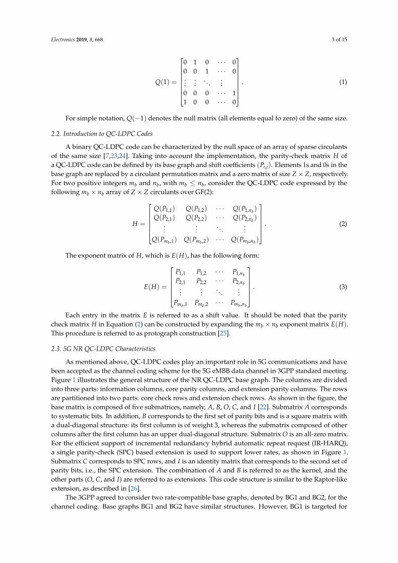
As mentioned above, QC-LDPC codes play an important role in 5G communications and havebeen accepted as the channel coding scheme for the 5G eMBB data channel in 3GPP standard meeting.Figure 1 illustrates the general structure of the NR QC-LDPC base graph. The columns are dividedinto three parts: information columns, core parity columns, and extension parity columns. The rowsare partitioned into two parts: core check rows and extension check rows. As shown in the figure, thebase matrix is composed of five submatrices, namely, A, B, O, C, and I [22]. Submatrix A correspondsto systematic bits. In addition, B corresponds to the first set of parity bits and is a square matrix witha dual-diagonal structure: its first column is of weight 3, whereas the submatrix composed of othercolumns after the first column has an upper dual-diagonal structure. Submatrix O is an all-zero matrix.For the efficient support of incremental redundancy hybrid automatic repeat request (IR-HARQ),a single parity-check (SPC) based extension is used to support lower rates, as shown in Figure 1.Submatrix C corresponds to SPC rows, and I is an identity matrix that corresponds to the second set ofparity bits, i.e., the SPC extension. The combination of A and B is referred to as the kernel, and theother parts (O, C, and I) are referred to as extensions. This code structure is similar to the Raptor-likeextension, as described in [26].
The 3GPP agreed to consider two rate-compatible base graphs, denoted by BG1 and BG2, for thechannel coding. Base graphs BG1 and BG2 have similar structures. However, BG1 is targeted for
Electronics 2019, 8, 668 4 of 15
larger block lengths (500 ≤ K ≤ 8448) and higher rates (1/3 ≤ R ≤ 8/9), whereas BG2 is targeted forsmaller block lengths (40 ≤ K ≤ 2560) and lower rates (1/5 ≤ R ≤ 2/3). The actual base graph usageand the definition of the two matrices are detailed in the NR standard specification TS 38.212 [27].The base graph that supports Kmax should support the following set of shift sizes Z, where Z = a× 2j
for a ∈ {2, 3, 5, 7, 9, 11, 13, 15} and 0 ≤ j ≤ 7.
Figure 1. Sketch of base parity check structure for the 5G NR QC-LDPC codes.
For base graphs BG1 and BG2, the number of shift coefficient designs is 8. All lift sizes are dividedinto eight sets based on parameter a, where a is used for the definition of the lifting-size a× 2j. The setof shift coefficients are listed in Table 1.
Table 1. Relationship between exponent matrices and sets of lifting size.
The shift value Pi,j can be calculated using the function Pi,j = f (Vij, Z), where Vi,j is the shiftcoefficient of the (i, j)-th element in the corresponding shift design. The function f is defined asEquation (4), in which mod denotes the modulo arithmetic:
Pi,j = f (Vi,j, z) =
{−1, if Vi,j = −1,
mod(Vi,j, z), else.(4)
The following procedures are the steps of constructing the parity check matrix of the target (N, K)QC-LDPC code with a given information block size K and code rate R = K/N. For a base graph, kbdenotes the number of information circulant columns; thus, if the lifting size is Z, K = Z× kb nominally.
Electronics 2019, 8, 668 5 of 15
Step 1: Obtain the base graph BG1 or BG2 and determine the value of kb for the given K and R.
– For BG1: kb = 22.
– For BG2: kb = 10 if K > 640; kb = 9 if 560 < K ≤ 640; kb = 8 if 192 < K ≤ 560;and kb = 6 elsewhere.
Step 2: Determine Z by selecting the minimum Z value in Table 2, such that kb × Z ≥ K.Step 3: After the lifting size Z is determined, the corresponding shift coefficient matrix is then selected
from Table 1 {Set 1, Set 2,. . . , Set 8} according to set Z.Step 4: Calculate the shifting coefficient value Pi,j by the modular Z operation, as discussed
in Equation (4).Step 5: Replace each entry in the final exponent matrix with the corresponding circulant permutation
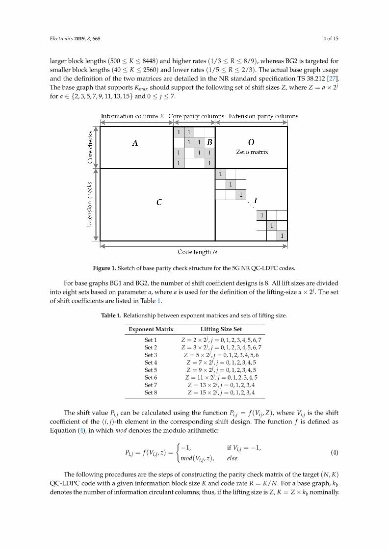
matrix or zero matrix of size Z × Z. The QC-LDPC code construction is completed anda parity check matrix H of size mbZ× nbZ is obtained. In 5G QC-LDPC codes, shorteningand puncturing is carried out to obtain the desired information lengths and rate adaption.Figure 2 presents an illustration of the encoding process of these codes
Table 2. Lifting size Z supported by standard 5G QC-LDPC codes.
Figure 2. Shortening by zero padding and puncturing of standard 5G QC-LDPC codes.
3. LDPC Encoding Algorithms
Given a parity check matrix H, the objective of LDPC encoding is to solve parity equations:
HCT = 0T , (5)
Electronics 2019, 8, 668 6 of 15
where C is the systematic codeword, which consists of the information bit vector S and paritycode vector P.
This section presents a review on two generic encoding methodologies for the implementation ofthe LDPC encoder: the Gaussian elimination method and the RU method.
3.1. LDPC Encoding with Gaussian Elinination
The Gaussian elimination is the most conventional method of encoding LDPC codes, which iscarried out by the multiplication of the generator matrix G, and contains a complexity quadratic in theblock length [19]. The unknown generator matrix G can be derived from the parity check matrix H.A generator matrix for code with a parity check matrix H can be obtained by carrying out Gauss–Jordanelimination on H in the following form:
H =[
A IN−K
], (6)
where A is an (N − K) × K binary matrix and IN−K is the identity matrix of order (N − K).The generator matrix is as follows:
G =[
IK AT]
. (7)
The codeword C is then obtained by multiplying the generator matrix G by the systematic bits Sas follows:
C = SG. (8)
The sequential LDPC encoder based on the multiplication of the G matrix requires a ROM to storethe generator matrix used to compute the codeword C. The main drawback of this approach is that,unlike parity check matrix H, the corresponding generator matrix G will most likely not be sparse.The complexity of this straightforward encoding algorithm is O(N2), where N is the number of bitsin a codeword. Therefore, the implementation of the matrix multiplication at the encoder results ina very high complexity. For an arbitrary parity check matrix, the construction of G should be avoidedand encoding should be carried out using back substitution with H.
3.2. LDPC Encoding with the RU Method
Instead of determining a generator matrix for H, an LDPC code can be directly encoded using theparity check matrix by transforming it into a lower triangular form and applying back substitution.The RU encoding method, which was proposed by Richardson and Urbanke [13], is a linear timeencoding method for sparse parity check matrices. The underlying principle is transformation usingonly row and column permutations, to reformulate a parity check matrix H into a sparse matrix.Therefore, this approach can reduce the complexity more than the G matrix multiplication method.The RU algorithm consists of two steps: a pre-processing step and actual encoding step.
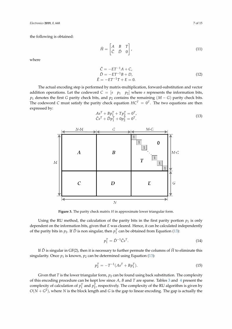
First, in the pre-processing step, the parity check matrix H is converted into the approximate lowertriangular (ALT) form, as shown in Figure 3. The parity check matrix H is given by the M× N matrix,where N is the block length of the code and M is the number of parity check equations. Given thatthe matrix transformation is realized solely by row and column permutations, the H matrix remainsa sparse matrix:
HT =
[A B TC D E
]. (9)
Here, the matrix T has a lower triangular form with 1s along the diagonal, and all the entriesabove the diagonal are 0s. By multiplying H from the left by[
I 0−ET−1 I
], (10)
Electronics 2019, 8, 668 7 of 15
the following is obtained:
H =
[A B TC D 0
], (11)
where
C = −ET−1 A + C,D = −ET−1B + D,
E = −ET−1T + E = 0.(12)
The actual encoding step is performed by matrix-multiplication, forward-substitution and vectoraddition operations. Let the codeword C = [s p1 p2] where s represents the information bits,p1 denotes the first G parity check bits, and p2 contains the remaining (M − G) parity check bits.The codeword C must satisfy the parity check equation HCT = 0T . The two equations are thenexpressed by:
AsT + BpT1 + TpT
2 = 0T ,CsT + DpT
1 + 0pT2 = 0T .
(13)
Figure 3. The parity check matrix H in approximate lower triangular form.
Using the RU method, the calculation of the parity bits in the first parity portion p1 is onlydependent on the information bits, given that E was cleared. Hence, it can be calculated independentlyof the parity bits in p2. If D is non singular, then pT
1 can be obtained from Equation (13):
pT1 = D−1CsT . (14)
If D is singular in GF(2), then it is necessary to further permute the columns of H to eliminate thissingularity. Once p1 is known, p2 can be determined using Equation (13):
pT2 = −T−1(AsT + BpT
1 ). (15)
Given that T is the lower triangular form, p2 can be found using back substitution. The complexityof this encoding procedure can be kept low since A, B and T are sparse. Tables 3 and 4 present thecomplexity of calculation of pT
1 and pT2 , respectively. The complexity of the RU algorithm is given by
O(N + G2), where N is the block length and G is the gap to linear encoding. The gap is actually the
Electronics 2019, 8, 668 8 of 15
number of rows of the parity check matrix that cannot be set into a triangular form using only row andcolumn permutations. With a small gap G, the lower encoding complexity for the code is achieved.
Table 3. Complexity analysis of pT1 calculation.
Operation Comment Complexity
AsT Multiplication by sparse matrix O(N)T−1 AsT Back substitution, T is lower triangular matrix O(N)
−ET−1[AsT ] Multiplication by sparse matrix O(N)CsT Multiplication by sparse matrix O(N)
C = −ET−1[AsT ] + CsT Addition O(N)−D−1CsT Multiplication by G× G matrix O(G2)
Table 4. Complexity analysis of pT2 calculation.
Operation Comment Complexity
AsT Multiplication by sparse matrix O(N)BpT
1 Multiplication by sparse matrix O(N)[AsT ] + [BpT
1 ] Addition O(N)−T−1(AsT + BpT
1 ) Back substitution, T is lower triangular O(N)
The disadvantage of encoding using the RU method is that there is no exact programmablestep-by-step algorithm. The multiple matrix calculations in this algorithm significantly limit thedevelopment of a rapid flexible encoder [28]. In addition, the RU method is subjected to a long criticalpath and odd constraints, which could render the LDPC encoder non-systematic [19].
4. Proposed 5G NR QC-LDPC Encoder Design
4.1. Proposed QC-LDPC Encoding Algorithm
This section presents an efficient scheme developed in this study for the construction of efficientencoders for 5G NR QC-LDPC codes. The proposed encoding method is based on the specialcharacteristics of 5G NR QC-LDPC codes, which are presented in Figure 1. The proposed architecturestarget low-complexity, while ensuring high-throughput. As reported in the literature review, basegraphs BG1 and BG2 have similar structures. In this paper, we focus our description on BG1 witha size of mb × nb (mb = 46, and nb = 68), which is the main 5G NR high rate base graph.
Let the codeword C = [s pa pc], where s denotes the systematic portion, which is divided into22 groups of Z bits, since the base graph BG1 has kb = nb−mb = 22 information bit columns. Moreover,s = [s1, s2, . . . , skb
], where each element of s is a vector of length Z. The information messages receivedby the encoder are stored in registers that are organized by kb blocks, denoted by si (i = 1, 2, . . . , kb),which correspond to the systematic blocks, where each consists of Z bits. Given that the encoder wasdesigned to read Z bits per clock cycle, it requires kb cycles to store all the information blocks. Moreover,the parity sequence can be grouped into sets of Z bits. Suppose that the parity portion of each messagep is split into two sub-components as follows: the first g = 4 parity bits pa = [pa1 , pa2 , . . . , pag ], and theremaining (mb − g) = 42 parity bits pc = [pc1 , pc2 , . . . , pcmb−g ] . More precisely, the encoded codewordcan be expressed as:
The parity check matrix H of 5G NR QC-LDPC codes can be partitioned into six matrices andpresented in the following form:
H =
[A B 0C1 C2 I
], (17)
Electronics 2019, 8, 668 9 of 15
where A is g× kb, B is g× g, C1 is (mb − g)× kb, and C2 is (mb − g)× g. Moreover, I is an identitymatrix with dimensions of (mb − g)× (mb − g). The encoding of LDPC codes is carried out using thefollowing defining equation:
HCT = 0T . (18)
Equation (18) can also be expressed as:
[A B 0C1 C2 I
] spa
pc
= 0T . (19)
Equation (19) is then naturally split into two equations, as follows:
ATs + BpT
a + 0pTc = 0T , (20)
C1sT + C2 pTa IpT
c = 0T . (21)
The proposed algorithm is performed in two steps. In the initial step, the parity bits in the firstportion pa are computed by solving Equation (20). The second step in the encoding process includesthe computation of the pc parity portions using Equation (21).
The first step in the encoder implementation is the determination of the pa part. Initially,Equation (20) is re-written in block form as follows:
a1,1 a1,2 · · · a1,kb
a2,1 a2,2 · · · a2,kb
a3,1 a3,2. . . a3,kb
a4,1 a4,2 · · · a4,kb
s1
s2...
skb
+
1 0 −1 −10 0 0 −1−1 −1 0 01 −1 −1 0
pa1
pa2
pa3
pa4
= 0. (22)
This can then be expanded into the following set of equations:
kb
∑j=1
a1,jsj + p(1)a1 + pa2 = 0, (23)
kb
∑j=1
a2,jsj + pa1 + pa2 + pa3 = 0, (24)
kb
∑j=1
a3,jsj + pa3 + pa4 = 0, (25)
kb
∑j=1
a4,jsj + p(1)a1 + pa4 = 0, (26)
where p(α)a1 denotes the αth (right) cyclic shifted version of pa1 for 0 ≤ α ≤ Z. By adding up all theabove equations, the following is obtained:
pa1 =4
∑i=1
kb
∑j=1
ai,jsj. (27)
It should be noted that a straightforward implementation of ai,jsj can be done with the use ofZ-bit cyclic shifters. Since ai,jsj is a circular right shift of sj with the shift coefficient defined by ai,j,the hardware complexity is trivial. Based on the definition below,
Electronics 2019, 8, 668 10 of 15
λi =kb
∑j=0
ai,jsj for i = 1, 2, 3, 4, (28)
the following can be obtained:
pa1 =4
∑i=1
λi, (29)
pa2 = λ1 + p(1)a1 , (30)
pa3 = λ3 + pa4 , (31)
pa4 = λ4 + p(1)a1 . (32)
From Equation (28), each λi value is computed by accumulating all the ai,jsj values. In Modulo 2,λi is obtained by carrying out XOR operations on all the elements of ai,jsj. The λi values can beestimated per clock cycle in g = 4 cycles. The first block of the parity bits pa1 is then calculated byaccumulating all the λi values. The remaining parity bits pai can be obtained using a method that canbe easily derived from Equations (30)–(32). This process can be done in two clock cycles since there isdependency between pa3 and pa4 . All the parity bits pa in the first parity portion are stored in registers.
In a second step, the pc portion can be easily determined based on Equation (21), where matricesC1 and C2 are given by
Upon the application of Equation (21), the elements of pc can be computed using thefollowing equations:
pc1 =kb
∑j=1
c1,jsj +g
∑j=1
c1,kb+j paj ,
pc2 =kb
∑j=1
c2,jsj +g
∑j=1
c2,kb+j paj ,
...
pcmb−g =kb
∑j=1
cmb−g,jsj +g
∑j=1
cmb−g,kb+j paj .
(34)
Similarly, ci,jsj represents a circular shift of sj with the shift coefficient defined by ci,j, and ci,kb+j paj
represents a circular shift of paj with the shift coefficient defined by ci,kb+j. As soon as ci,jsj and ci,kb+j paj
have been obtained, they can be used to determine the value of the corresponding parity bits in thesecond parity portion pc. This step can be performed in a single clock cycle. Hence, all the pc paritybits can be acquired in (mb − g) clock cycles. The encoded codeword is then a combination of theoriginal message s and the two calculated parity portions pa and pc.
4.2. Proposed QC-LDPC Encoder Architecture
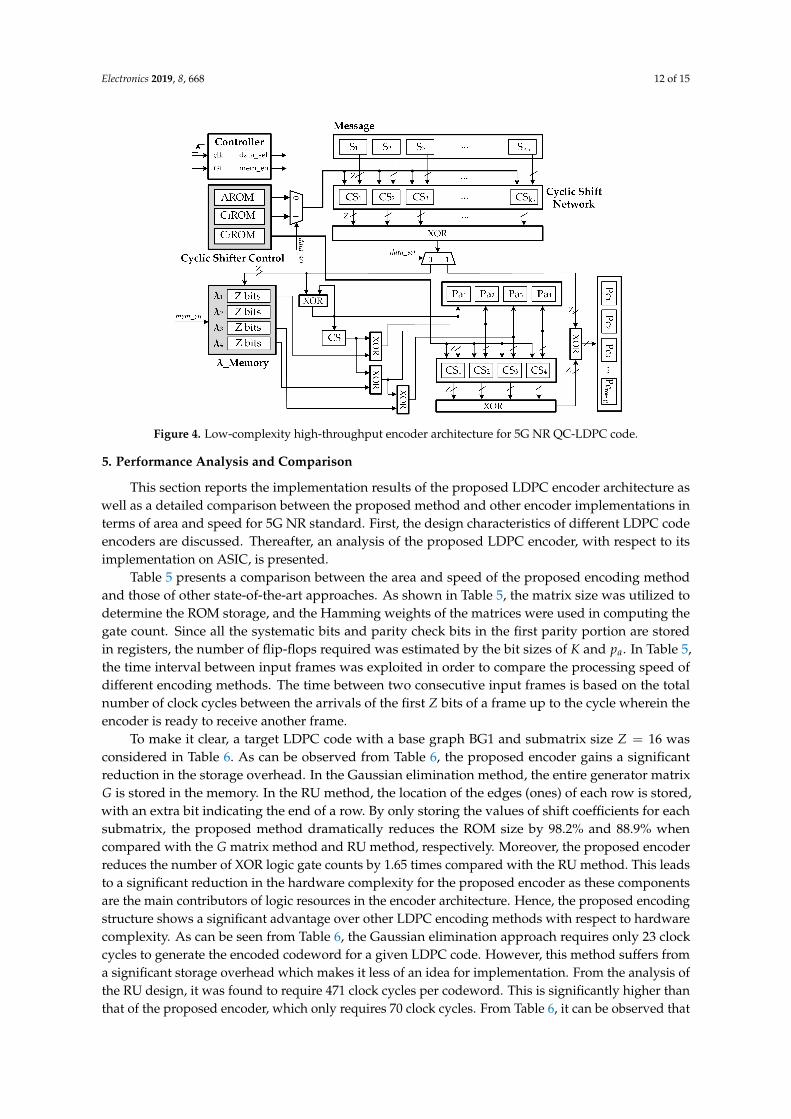
Figure 4 details the overall block diagram for the proposed low complexity 5G NR QC-LDPCcode encoder. The hardware architectures were designed to conduct the encoding process throughsteps defined in Equations (29)–(32) and (34). In the first step, the computation of the parity bits inthe first portion pa is carried out. From Equation (28), each λi value is computed by accumulatingall the cyclic shift results of sj. Since the information message s consists of kb blocks of Z bits, a totalof kb = 22 barrel shifters of size Z, which are denoted by CSj, j = 1, 2, ..., kb, are required for the
Electronics 2019, 8, 668 11 of 15
circular shift process. The vector addition of all the λi components is then carried out by the XOR trees.Each intermediate λi value corresponding to Equation (28) can be estimated per clock cycle and storedin the λ_memory to be used later. Thus, the value of pa1 can be obtained in g = 4 clock cycles when allλi values are obtained and stored in memory. The remaining parity bits of pa can be obtained in 2 clockcycles with the use of XOR gates.The objective of the second step is the calculation of the parity bits inthe second portion pc. According to (34), the parity blocks pci can be achieved by the vector addition ofci,jsj and ci,kb+j paj . The value of ci,jsj is also computed by accumulating all the cyclic shift results ofsj. In this step, the overall hardware complexity can be further decreased by exploiting the sharingtechnique. More specifically, the barrel shifters and XOR trees are reused for the computation of pc inthis step. Control signals are generated by the controller block. The value of ci,kb+j paj is estimated byaccumulating all the cyclic shift results of paj . The required number of Z–bit barrel shifters is g = 4.The main blocks of the proposed architecture can be described as follows.
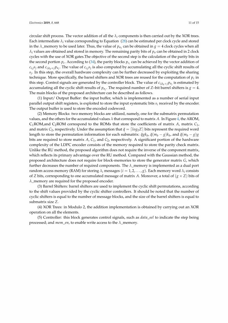
(1) Input/ Output Buffer: the input buffer, which is implemented as a number of serial inputparallel output shift registers, is exploited to store the input systematic bits si received by the encoder.The output buffer is used to store the encoded codeword.
(2) Memory Blocks: two memory blocks are utilized, namely, one for the submatrix permutationvalues, and the others for the accumulated values λ that correspond to matrix A. In Figure 4, the AROM,C1ROM,and C2ROM correspond to the ROMs that store the coefficients of matrix A, matrix C1,and matrix C2, respectively. Under the assumption that q = dlog2Ze bits represent the required wordlength to store the permutation information for each submatrix: qgkb, q(mb − g)kb, and q(mb − g)gbits are required to store matrix A, C1, and C2, respectively. A significant portion of the hardwarecomplexity of the LDPC encoder consists of the memory required to store the parity check matrix.Unlike the RU method, the proposed algorithm does not require the inverse of the component matrix,which reflects its primary advantage over the RU method. Compared with the Gaussian method, theproposed architecture does not require for block-memories to store the generator matrix G, whichfurther decreases the number of required components. The λ_memory is implemented as a dual portrandom access memory (RAM) for storing λi messages (i = 1, 2, . . . , g). Each memory word λi consistsof Z bits, corresponding to one accumulated message of matrix A. Moreover, a total of (g× Z) bits ofλ_memory are required for the proposed encoder.
(3) Barrel Shifters: barrel shifters are used to implement the cyclic shift permutations, accordingto the shift values provided by the cyclic shifter controllers. It should be noted that the number ofcyclic shifters is equal to the number of message blocks, and the size of the barrel shifters is equal tosubmatrix size Z.
(4) XOR Trees: in Modulo 2, the addition implementation is obtained by carrying out an XORoperation on all the elements.
(5) Controller: this block generates control signals, such as data_sel to indicate the step beingprocessed; and mem_en, to enable write access to the λ_memory.
Electronics 2019, 8, 668 12 of 15
Figure 4. Low-complexity high-throughput encoder architecture for 5G NR QC-LDPC code.
5. Performance Analysis and Comparison
This section reports the implementation results of the proposed LDPC encoder architecture aswell as a detailed comparison between the proposed method and other encoder implementations interms of area and speed for 5G NR standard. First, the design characteristics of different LDPC codeencoders are discussed. Thereafter, an analysis of the proposed LDPC encoder, with respect to itsimplementation on ASIC, is presented.
Table 5 presents a comparison between the area and speed of the proposed encoding methodand those of other state-of-the-art approaches. As shown in Table 5, the matrix size was utilized todetermine the ROM storage, and the Hamming weights of the matrices were used in computing thegate count. Since all the systematic bits and parity check bits in the first parity portion are storedin registers, the number of flip-flops required was estimated by the bit sizes of K and pa. In Table 5,the time interval between input frames was exploited in order to compare the processing speed ofdifferent encoding methods. The time between two consecutive input frames is based on the totalnumber of clock cycles between the arrivals of the first Z bits of a frame up to the cycle wherein theencoder is ready to receive another frame.
To make it clear, a target LDPC code with a base graph BG1 and submatrix size Z = 16 wasconsidered in Table 6. As can be observed from Table 6, the proposed encoder gains a significantreduction in the storage overhead. In the Gaussian elimination method, the entire generator matrixG is stored in the memory. In the RU method, the location of the edges (ones) of each row is stored,with an extra bit indicating the end of a row. By only storing the values of shift coefficients for eachsubmatrix, the proposed method dramatically reduces the ROM size by 98.2% and 88.9% whencompared with the G matrix method and RU method, respectively. Moreover, the proposed encoderreduces the number of XOR logic gate counts by 1.65 times compared with the RU method. This leadsto a significant reduction in the hardware complexity for the proposed encoder as these componentsare the main contributors of logic resources in the encoder architecture. Hence, the proposed encodingstructure shows a significant advantage over other LDPC encoding methods with respect to hardwarecomplexity. As can be seen from Table 6, the Gaussian elimination approach requires only 23 clockcycles to generate the encoded codeword for a given LDPC code. However, this method suffers froma significant storage overhead which makes it less of an idea for implementation. From the analysis ofthe RU design, it was found to require 471 clock cycles per codeword. This is significantly higher thanthat of the proposed encoder, which only requires 70 clock cycles. From Table 6, it can be observed that
Electronics 2019, 8, 668 13 of 15
the number of clock cycles required per codeword for the encoding of the proposed encoder designdecreased to 14.8% of that of RU method.
Table 5. Comparison between Gaussian method, RU method, and proposed method.
Memory (bits) ROM = kbmbZ2 ROM = (245x + 29y + 274)Z ROM = q[mb(kb + g)− g2]λ_mem = gZ
Speed (clock cycles) kb + 1 28Z + kb + 1 nb + 2
Where q = dlog2Ze; x = dlog2(kbZ)e; y = dlog2(gZ)e.
Table 6. Comparison between Gaussian method, RU method, and proposed method for submatrix sizeZ = 16.
Gaussian RU Proposed
Area
Flip-flops 352 416 416
XOR gates 258,336 764 464
AND gates 259,072 – –
Barrel shifter (Z bits) – – 27
Memory (bits) ROM = 259,072 ROM = 42,488ROM = 4720λ_mem = 64
Speed (clock cycles) 23 471 70
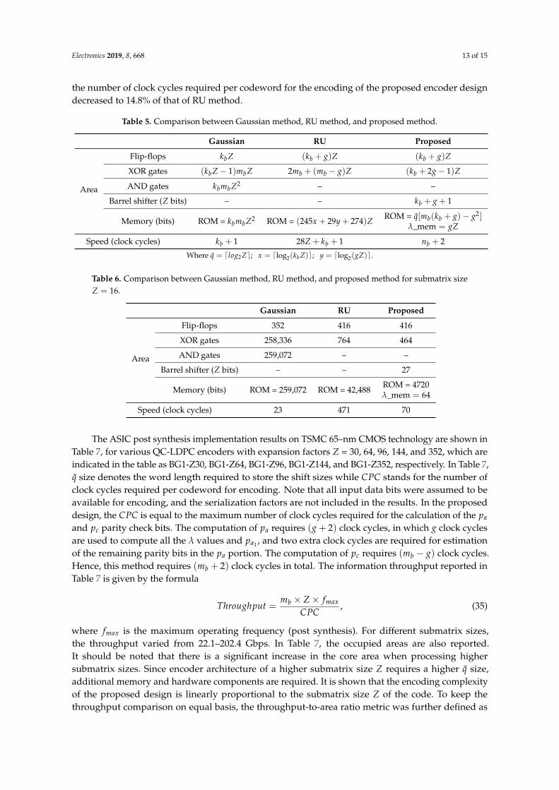
The ASIC post synthesis implementation results on TSMC 65–nm CMOS technology are shown inTable 7, for various QC-LDPC encoders with expansion factors Z = 30, 64, 96, 144, and 352, which areindicated in the table as BG1-Z30, BG1-Z64, BG1-Z96, BG1-Z144, and BG1-Z352, respectively. In Table 7,q size denotes the word length required to store the shift sizes while CPC stands for the number ofclock cycles required per codeword for encoding. Note that all input data bits were assumed to beavailable for encoding, and the serialization factors are not included in the results. In the proposeddesign, the CPC is equal to the maximum number of clock cycles required for the calculation of the pa
and pc parity check bits. The computation of pa requires (g + 2) clock cycles, in which g clock cyclesare used to compute all the λ values and pa1 , and two extra clock cycles are required for estimationof the remaining parity bits in the pa portion. The computation of pc requires (mb − g) clock cycles.Hence, this method requires (mb + 2) clock cycles in total. The information throughput reported inTable 7 is given by the formula
Throughput =mb × Z× fmax
CPC, (35)
where fmax is the maximum operating frequency (post synthesis). For different submatrix sizes,the throughput varied from 22.1–202.4 Gbps. In Table 7, the occupied areas are also reported.It should be noted that there is a significant increase in the core area when processing highersubmatrix sizes. Since encoder architecture of a higher submatrix size Z requires a higher q size,additional memory and hardware components are required. It is shown that the encoding complexityof the proposed design is linearly proportional to the submatrix size Z of the code. To keep thethroughput comparison on equal basis, the throughput-to-area ratio metric was further defined as
Electronics 2019, 8, 668 14 of 15
TAR = Throughput/Area (Gbps/mm2). For all the considered submatrix sizes in Table 7, the TARranged from 520–597 Gbps/mm2.
Based on the implementation results presented above, it is clear that the design methodologyis applicable to different submatrix sizes and offers a significantly high area efficiency and highinformation throughput, which is more than enough to satisfy the throughput requirement for the 5GNR standard.
Table 7. ASIC implementation results of LDPC encoders for different lifting sizes Z = 30, 64, 96, 144,and 352.
Area (mm2) 0.037 0.077 0.117 0.171 0.389Gate counts 45.9 K 96 K 146.3 K 214 K 486.4 K
TAR † (Gbps/mm2) 597 569 525 520 520† TAR = Throughput/Area.
6. Conclusions
In this paper, a novel low-complexity high-throughput encoder approach for the 5G NR standardis proposed. Based on the proposed encoding algorithm, five encoder architectures with differentsubmatrix sizes were implemented. The derived architecture exhibited a significantly lower hardwarecomplexity, as it decreased the memory and logic component requirements. The proposed designdemonstrates a superior performance to the alternative methods. Moreover, the synthesis resultsrevealed that the proposed design is appropriate for the high throughput 5G standard.
Author Contributions: T.T.B.N. conceptualized the idea of this research, conducted experiments, collected data,and prepared the original version. T.N.T. reviewed, analyzed data, and updated the manuscript. H.L. supervised,validated, reviewed, and supported the research with funding.
Funding: This work was supported by the INHA UNIVERSITY Research Grant.
Conflicts of Interest: The authors declare no conflict of interest.
References
1. Gallager, R.G. Low-Density Parity-Check Codes; MIT Press: Cambridge, MA, USA, 1963.2. MacKay, D.J.C.; Neal, R.M. Near Shannon Limit Performance of Low-Density Parity-Check Codes.
Electron. Lett. 1996, 32, 1645–1646. [CrossRef]3. Huo, Y.; Dong, X.; Xu, W. 5G Cellular User Equipment: From Theory to Practical Hardware Design.
IEEE Access 2017, 5, 13992–14010. [CrossRef]4. Session Chairman (Nokia). Chairman’s Notes of Agenda Item 7.1.5 Channel Coding and Modulation, 3GPP
TSG RAN WG1 Meeting No. 87, R1-1613710 (2016). Available Online: https://portal.3gpp.org/ngppapp/CreateTdoc.aspx?mode=view&contributionId=752413 (accessed on 22 May 2019).
5. Richardson, T.; Kudekar, S. Design of Low-Density Parity Check Codes for 5G New Radio. IEEE Commun. Mag.2018, 56, 28–34. [CrossRef]
6. Ji, W.; Wu, Z.; Zheng, K.; Zhao, L.; Liu, Y. Design and Implementation of a 5G NR System Based on LDPC inOpen Source SDR. In Proceedings of the 2018 IEEE Globecom Workshops (GC Wkshps), Abu Dhabi, UAE,9–13 December 2018; pp. 1–6.
7. Tang, H.; Xu, J.; Kou, Y.; Lin, S.; Abdel-Ghaffar, K. On Algebraic Construction of Gallager and CirculantLow-Density Parity-Check Codes. IEEE Trans. Inf. Theory 2004, 50, 1269–1279. [CrossRef]
9. Nguyen, T.T.B; Lee, H. Low-Complexity Multi-mode Multi-way Split-row Layered LDPC Decoder for GigabitWireless Communications. Integration 2018. [CrossRef]
10. Ajaz, S.; Lee, H. Efficient multi-Gb/s multi-mode LDPC decoder architecture for IEEE 802.11ad applications.Integration 2015, 51, 21–36. [CrossRef]
11. Ajaz, S.; Lee, H. An efficient radix-4 Quasi-cyclic shift network for QC-LDPC decoders. IEICE Electron. Express2014, 11, 1–6. [CrossRef]
12. Ajaz, S.; Lee, H. Reduced-complexity Local Switch Based Multi-mode QC-LDPC Decoder Architecture forGigabit Wireless Communications. IET Electron. Lett. 2013, 49, 1246–1248. [CrossRef]
17. Ilani, I. Designing and Encoding QC-LDPC Codes Using Matrices over Commutative Rings. In Proceedingsof the 2016 IEEE International Conference on the Science of Electrical Engineering (ICSEE), Eilat, Israel, 16–18November 2016; pp. 1–5.
18. Jung, Y.; Chung, C.; Jung, Y.; Kim, J. 7.7 Gbps Encoder Design for IEEE 802.11ac QC-LDPC Codes. J. Semicond.Technol. Sci. 2014, 14, 419–425. [CrossRef]
19. Cohen, A.E.; Parhi, K.K. A Low-Complexity Hybrid LDPC Code Encoder for IEEE 802.3an (10GBase-T)Ethernet. IEEE Trans. Signal Process. 2009, 57, 4085–4094. [CrossRef]
20. Zhang, P.; Liu, C.; Jiang, L. Efficient Encoding of QC-LDPC Codes Based on Rotate-left-accumulator Circuits.Electron. Lett. 2013, 49, 810–812. [CrossRef]
21. Jung, Y.; Kim, J. Memory-efficient and High-speed LDPC Encoder. Electron. Lett. 2010, 46, 1035–1036.[CrossRef]
22. Li, H.; Bai, B.; Mu, X.; Zhang, J.; Xu, H. Algebra-Assisted Construction of Quasi-Cyclic LDPC Codes for 5GNew Radio. IEEE Access 2018, 6, 50229–50244. [CrossRef]
24. Chen, L.; Lan, L.; Djurdjevic, I.; Lin, S.; Abdel-Ghaffar, K. An Algebraic Method for Constructing Quasi-cyclicLDPC Codes. In Proceedings of the International Symposium on Information Theory and Its Applications,Parma, Italy, 10–13 October 2004; pp. 535–539.
25. Li, J.; Lin, S.; Abdel-Ghaffar, K.; Ryan, W.; Costello, D.J., Jr. LDPC Code Designs, Constructions, and Unification;Cambridge University Press: Cambridge, UK, 2017.
27. Ad-Hoc chair (Nokia). Chairman’s Notes of Agenda Item 7.1.4. Channel Coding, 3GPP TSG RAN WG1Meeting AH 2, R1-1711982 (2017). Available Online: https://portal.3gpp.org/ngppapp/CreateTdoc.aspx?mode=view&contributionId=805088 (accessed on 22 May 2019).
28. Yasotharan, H.; Carusone, A.C. A Flexible Hardware Encoder for Systematic Low-density Parity-check Codes.In Proceedings of the 52nd IEEE International Midwest Symposium on Circuits and Systems, Cancun, Mexico,2–5 August 2009; pp. 54–57.


![A Massively Parallel Implementation of QC-LDPC Decoder ...gw2/pdf/sasp2011_gpu_ldpc_long.pdfQuasi-Cyclic LDPC (QC-LDPC) codes [1] have been widely used in many practical systems, such](https://static.documents.pub/doc/80x56/608577e15da5786347664f4c/a-massively-parallel-implementation-of-qc-ldpc-decoder-gw2pdfsasp2011gpuldpclongpdf.jpg)


![Design LDPC Cyclepeng/itw07.pdfoptimized binary LDPC code in [5] by 0.38 dB. Due to its highly irregular degree sequence, the encoding complexity of the optimized binary LDPC code](https://static.documents.pub/doc/80x56/5e6fbb682ffa9d6ab8128325/design-ldpc-cycle-pengitw07pdf-optimized-binary-ldpc-code-in-5-by-038-db-due.jpg)
