Efficient trimmed NURBS tessellation Ákos Balázs [email protected]Michael Guthe University of Bonn Institute of Computer Science II Römerstraße 164 D-53117 Bonn, Germany [email protected]Reinhard Klein [email protected]ABSTRACT Interactive rendering of trimmed NURBS models is of great importance for CAD systems. For this the model needs to be transformed into a polygonal representation. This transformation can be either performed in a preprocessing step, at the cost of losing the capability to edit the surfaces, or on the fly during rendering. Since the number of frames per second is usually critical, efficient on the fly tessellation of trimmed NURBS surfaces is very important for interactive rendering and editing of such models. In this paper we present an efficient – with respect to both runtime and to the number of generated triangles – tessellation algorithm for trimmed NURBS surfaces that is capable of guaranteeing a specified geometric approximation error. When affordable by the subsequent steps in the pipeline, an approximate error of the tessellation can also be used leading to fewer triangles. Keywords Trimmed NURBS rendering, trimmed NURBS real-time tessellation 1. INTRODUCTION In industry the design of models for prototyping and production is performed with CAD systems that are usually based on trimmed NURBS surfaces. They have the advantage to describe almost every shape conveniently. Since even today’s advanced graphics hardware is unable to directly render trimmed NURBS models, they need to be transformed into a renderable (e.g. polygonal) representation. This process is usually referred to as “tessellation.” Since complex models may consist of several thousand trimmed NURBS patches a fast, but nevertheless triangle sparing tessellation algorithm is required. Main Contribution The main contribution of this paper is an efficient trimmed NURBS tessellation algorithm that is suitable for interactive editing and rendering, and it usually produces much fewer triangles than previous methods. Furthermore, our algorithm is able to either guarantee a specified approximation error which is required e.g. when the patches are stitched together for rendering and/or further processing, or to generate a mesh with approximately the specified error for rendering only that consists of even less triangles. 2. PREVIOUS WORK The rendering of trimmed NURBS surfaces has received a lot of attention from researchers over the last decade due to its industrial relevance. Different approaches emerged for visualization, e.g. ray- tracing the surfaces (e.g. [Nis90]), pixel level subdivision (e.g. [Sha88]) or polygon tessellation (e.g. [For90, Kle95]), of which the triangle based methods are generally much faster due to recent advances in graphics hardware. E.g. Baxter et al. [Bax02] developed a parallelized system for interactive walkthroughs of huge triangulated models (e.g. generated from trimmed NURBS models), but it requires a multiprocessor system and massive amounts of memory for storing the static hierarchical levels of detail. Additionally they have developed out-of-core techniques [Ali99] to handle complex models on a cluster of standard PCs. Another approach for rendering trimmed NURBS models is tessellating the patches during runtime. These methods can be divided into two categories: adaptive uniform and fully adaptive subdivision. Permission to make digital or hard copies of all or part of this work for personal or classroom use is granted without fee provided that copies are not made or distributed for profit or commercial advantage and that copies bear this notice and the full citation on the first page. To copy otherwise, or republish, to post on servers or to redistribute to lists, requires prior specific permission and/or a fee. Journal of WSCG, Vol.12, No.1-3, ISSN 1213-6972 WSCG’2004, February 2-6, 2004, Plzen, Czech Republic. Copyright UNION Agency – Science Press
ABSTRACT Interactive rendering of trimmed NURBS models is of great importance for CAD systems. For this the model needs to be transformed into a polygonal representation. This transformation can be either performed in a preprocessing step, at the cost of losing the capability to edit the surfaces, or on the fly during rendering. Since the number of frames per second is usually critical, efficient on the fly tessellation of trimmed NURBS surfaces is very important for interactive rendering and editing of such models. In this paper we present an efficient – with respect to both runtime and to the number of generated triangles – tessellation algorithm for trimmed NURBS surfaces that is capable of guaranteeing a specified geometric approximation error. When affordable by the subsequent steps in the pipeline, an approximate error of the tessellation can also be used leading to fewer triangles.
1. INTRODUCTION In industry the design of models for prototyping and production is performed with CAD systems that are usually based on trimmed NURBS surfaces. They have the advantage to describe almost every shape conveniently. Since even today’s advanced graphics hardware is unable to directly render trimmed NURBS models, they need to be transformed into a renderable (e.g. polygonal) representation. This process is usually referred to as “tessellation.” Since complex models may consist of several thousand trimmed NURBS patches a fast, but nevertheless triangle sparing tessellation algorithm is required.
Main Contribution The main contribution of this paper is an efficient trimmed NURBS tessellation algorithm that is suitable for interactive editing and rendering, and it usually produces much fewer triangles than previous methods. Furthermore, our algorithm is able to either
guarantee a specified approximation error which is required e.g. when the patches are stitched together for rendering and/or further processing, or to generate a mesh with approximately the specified error for rendering only that consists of even less triangles.
2. PREVIOUS WORK The rendering of trimmed NURBS surfaces has received a lot of attention from researchers over the last decade due to its industrial relevance. Different approaches emerged for visualization, e.g. ray-tracing the surfaces (e.g. [Nis90]), pixel level subdivision (e.g. [Sha88]) or polygon tessellation (e.g. [For90, Kle95]), of which the triangle based methods are generally much faster due to recent advances in graphics hardware. E.g. Baxter et al. [Bax02] developed a parallelized system for interactive walkthroughs of huge triangulated models (e.g. generated from trimmed NURBS models), but it requires a multiprocessor system and massive amounts of memory for storing the static hierarchical levels of detail. Additionally they have developed out-of-core techniques [Ali99] to handle complex models on a cluster of standard PCs.
Another approach for rendering trimmed NURBS models is tessellating the patches during runtime. These methods can be divided into two categories: adaptive uniform and fully adaptive subdivision.
Permission to make digital or hard copies of all or part of this work for personal or classroom use is granted without fee provided that copies are not made or distributed for profit or commercial advantage and that copies bear this notice and the full citation on the first page. To copy otherwise, or republish, to post on servers or to redistribute to lists, requires prior specific permission and/or a fee. Journal of WSCG, Vol.12, No.1-3, ISSN 1213-6972 WSCG’2004, February 2-6, 2004, Plzen, Czech Republic. Copyright UNION Agency – Science Press
For the uniform subdivision [Rok89, Sán03], the surface is tessellated using a regular grid in parameter space. The fully adaptive subdivision was first used by Forsey et al. [For90]. Kumar et al. [Kum97] introduced the notion of super-surfaces to close cracks between adaptively tessellated patches. A drawback of this method is that a priori connectivity information is required. This information is generated by clustering sets of trimmed NURBS patches into so-called super-surfaces that need to be sewn at run-time. The stitching was improved by Guthe et al. [Gut02] introducing the Seam-Graph data structure. Recently Balázs et al. [Bal03] developed a method to use programmable graphics hardware to fill cracks between adjacent patches and therefore supporting the visualization of animated NURBS models. All these methods have in common, that they require knowledge of the exact approximation error along the trimming curves. An approximation error over the surface is not required for these algorithms to work, but it may be required in a subsequent step of the pipeline. Therefore, our algorithm is able to guarantee a specific approximation error for both trimming and surface or to use an approximate error for the surface.
Independently of the actual algorithm used for tessellation, the surface itself has to be evaluated at the vertices of the generated mesh. A complete survey on different NURBS surface evaluation methods can be found in [Sán03]. Since the conclusion of this survey is that direct evaluation is the fastest of all methods we chose this approach.
3. ALGORITHM OVERVIEW The overall algorithm to tessellate a NURBS surface works as follows: • Convert trimming curves into sequences of 3d
4. CONVERSION OF TRIMMING In order to be able to guarantee an error in Euclidean space we have to measure the Hausdorff distance [Kle96] between the 3d trimming curve and the current approximation. To provide a tighter upper bound for the approximation error of the trimming curve by line segments than Kahlesz et al. [Kah02]
we elevate the trimming curves into Euclidian space. We achieve this by first converting the trimming curves into their Bézier form which is then degree reduced by the following algorithm from [Far96]: • Calculate new control points with:
( )0 0
1 1
1
1
1 1
2 01
i ii
n n
i ii
P PnP n i P
P ; i , ,ni
P PnP iP
P ; i n , ,n
+ +
−
−
=
− −= = −
=
−= = −
−
…
…
• If i iP P≈ for all 0 i n≤ ≤ then the curve was losslessly degree reducible and the process is repeated with the new control points
( )1i i i i iP P Pλ λ= + − with 0iλ = for 2ni < ,
12iλ = for 2
ni = and 1iλ = for 2ni > .
Since the blossom [Far96] of a Bézier curve results in a 3d Bézier curve only if it lies completely on a Bézier tensor product surface, the Bézier trimming loops are cut at the spans of the NURBS surface in order to restrict them to one Bézier surface patch. The degree of a 3d Bézier curve which is constructed by elevating a 2d Bézier curve of degree 2dd by a NURBS patch can be at most ( )3 2d d u vd d d d= + , where ud and vd are the degrees of the surface in the u and v -direction. Since a Bézier curve of degree n can be represented as three polynomes of degree n, it is defined uniquely by 1n + arbitrary points on the curve. For numerical stability we therefore construct it by evaluating 3 1dd + equally
distributed parameter values ( 3
3 3 3
11 20 1d
d d d
dd d d, , , , ,−… ) on
the trimming curve and then calculating the 3d Bézier curve defined by these points. This leads to a linear system of equations with a nonsingular matrix [Pie97]:
( ) ( )
( ) ( )
( )
( )
0 0 00 0
0
nn n n
n n nn nn n n
B B P C
B B P C
=
,
where iB are the basis functions, iP the unknown control points of the 3d Bézier curve, and ( )C i are the evaluated points of the curve sampled at the regularly distributed parameter values. In order to have numerical stability we use singular value decomposition [Pre92]. Since the complexity of the SVD for an n n× matrix is 2( )O n log n , a maximum degree (e.g. 20) can be used.
Finally the resulting 3d Bézier curve is degree reduced using the above described algorithm and stored along with its corresponding (cut) 2d trimming curve. To guarantee lossless degree reduction we only allow a very small epsilon when checking the control points of the reduced curve with i iP P≈ for all 0 i n≤ ≤ . Note, that the generated 3d Bézier curves exactly match the original trimming curves – except for numerical inaccuracy – and are not an approximation.
5. APPROXIMATION As we calculated the 3d trimming curves (see section 4) this allows the independent approximation of the trimming curves and the untrimmed surface. This dual approximation technique reduces the total number of triangles generated for a given error bound.
Trimming Loops Since each trimming curve segment is restricted to one surface span, subsequent curve segments (or curves) may be collinear in Euclidean space. In order to avoid redundant vertices we apply a standard line simplification algorithm – guaranteeing a given Hausdorff distance between the original and the simplified line segments – to each approximated trimming loop. Since this introduces an additional error, we approximate the trimming curves with fixed portion (γ ) of the desired error and then simplify each complete trimming loop with (1 )γ− of the error as maximum Hausdorff distance. A good tradeoff between runtime and number of edges is
34γ = , which we used for our tests.
For the approximation we use the convex hull property of the 3d Bézier curve which leads to the following error bound:
( ) ( )( )
( )( )
11 0 02
0 02
0
112
0 1
nline i i nn
i n
n
max P P P P
P P P Pmax ,min ,
P P
ε λ
λ
−=−
≤ − − − −
− − =
−
If an approximation by a line is not sufficient we can either use the control point jP that has the largest distance to the linear approximation and subdivide at
isubdiv nt = or apply a midpoint subdivision.
Theoretically using arbitrary subdivision should reduce the number of points required to approximate the trimming curve (see Fig.1), but as it turned out during our tests (see Section 9), the midpoint subdivision produces slightly less trimming edges.
This is due to the fact that subdivision at control points only is not fine grained enough.
Although in theory trimming curves should never intersect, in practice due to modeling or other errors they often do. To handle such models we must add a correction step for the trimming loops. The algorithm works similarly to the line sweep algorithm [Ben79]. At each intersection an intermediate point is inserted and then intersection free trimming loops are built.
NURBS Surfaces Traditional runtime tessellation algorithms either use a grid or a quadtree to subdivide the surface for approximation. Since even the quadtree is not completely adaptive, we have developed a new approximation algorithm based on kd-tree subdivision. The approximation error for the current subdivision can be calculated using the distance between the control points and the bilinear surface approximation. Since the two triangles that would be generated for this tree node cannot resemble a bilinear quad patch an additional approximation error needs to be taken into account which leads to the following estimated error [Kah02]:
100 0 04 , withconservative bilin m n mnP P P Pε ε≤ + − − +
( )0 0
wherei m, j n
jibilin ij m ni , j
max P S , ,ε≤ ≤
= =≤ −
( ) ( ) ( )( )
( )( )00 0
0
1 1
1n
m mn
S a,b b a P aP
b a P aP
= − − + +
− +
Since this error measure is still a (sometimes significant) overestimation, an approximate error measure can also be used if the approximation inside a patch has not to be guaranteed. In order to calculate this approximate error we still use the above equations, but replace the control point ijP with
( )i jS ,α β , where iα and jβ are the parameter
values corresponding to the control point ijP .
Figure 1. Curve approximation with midpoint (top) and arbitrary (bottom) subdivision.
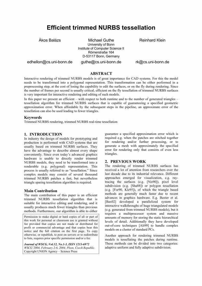
If the estimated approximation error exceeds the desired error for the NURBS surface the tree node needs to be subdivided. If a quadtree is used, the node is split at the midpoint in the parameter domain. On surfaces with high curvature in one direction of the parameter domain and low curvature in the other direction (e.g. a cylindrical surface) this leads to an unnecessary high subdivision in the low curvature direction. As shown in Fig.2, using a binary subdivision solves this problem, but it still suffers from the problem that unnecessary subdivisions are applied if the curvature of the surface is highly variant.
This can be solved by using arbitrary subdivision of the surface. Since a NURBS surface can only be subdivided either in the u or in the v direction, this leads to a kd-tree subdivision. We subdivide at ( )k l
m n, for which the following holds:
( ) ( ) ( )0 0
wherei m, j n
jk l k l iijm n m n m ni , j
S , S , max P S , ,≤ ≤
= =− = −
0 , 0k m l n≤ ≤ ≤ ≤ and S is the bilinear approximation of S. For the direction of the subdivision we choose the one for which the line subdividing the kd-tree node is closer to ( )k l
m nS , (see Fig.3).
Since we already have the appropriate approximation for the trimming loops of the surface, we can reduce the number of unnecessary subdivisions by restricting the parameter domain to the bounding box of the trimming loop approximation in parameter space.
6. TRIMMING To perform the actual trimming we use an extended version of the trimming algorithm developed by Kahlesz et al. [Kah02]. By inserting the approximation of trimming curves into the mesh as (directed) half-edges (the orientation is the same as the direction of the trimming curve) and replacing all faces from the mesh with appropriate new faces we essentially create a directed graph of half-edges. This graph spans the whole parameter space of the surface, and has directed edges exactly where the trimming curves are in the parameter space. The trimming is performed by traveling along the half-edges. The pseudo-code of the traversal is: findDirectedEdge() while there are directed edges left while we have a valid edge store start node handleEdge() getNextEdge() if we are back at the start node handleEdge() triangulate() getOutGoingEdge() findDirectedEdge() The functions used in the pseudo code are the following: • findDirectedEdge() Find an arbitrary directed
edge in the graph. • handleEdge() If this edge was directed, delete it
from the graph. Otherwise, make it a directed edge, with the orientation being the opposite of the one in which we traversed this edge.
• triangulate() Given a sequence of nodes defining a polygon, triangulate it. (See Section 7.)
• getNextEdge() Given a node and an edge, find the leftmost edge which is not equal to the given edge.
• getOutGoingEdge() Given a node, find the outgoing edge: that is, an edge which is directed and is pointing out of this node. Note that the construction of the graph guarantees that there can be at most one such edge.
Whenever the graph traversal algorithm finds a closed polygon, we have to triangulate it. Note that the polygon may not be convex if a trimming curve is part of it. This algorithm has the problem that it cannot handle holes inside a mesh face. Therefore, each clockwise trimming loop is checked if it is contained completely inside a face. If this is the case two additional half-edge pairs are inserted to connect the
Figure 2. Quadtree and binary subdivision on a cylindrical surface.
Figure 3. Finding the subdivision direction and parameter for the kd-tree.
worst point
approximations
upper left and lower right vertices of the face to their nearest vertex of the trimming loop.
7. TRIANGULATION As the constrained triangulation of point clouds is a non-trivial problem, practically all NURBS tessellation algorithms generate the final triangulation in the parameter domain of the surface. This is reasonable as long as the surface does not deform the polygon too much, which using our algorithm cannot happen due to the error control. Since polygons created from kd-tree or octree cells are always convex (they are essentially rectangles with additional points inserted along the edges), we are able to use a simple linear time triangulation algorithm: • Find the upper left vertex of the polygon and
build a triangle with the left and right neighboring vertices.
• Iteratively take the current edge and build a triangle with the upper left of the two adjacent vertices.
Since polygons containing trimming curves may be non-convex, we must check if this condition holds. Since a polygon is non-convex if at least one angle is greater than 180 degrees, we can perform a simple check that has the complexity of ( )O n . If the polygon is convex the above algorithm can be applied. If this is not the case, we use the ( )O nlog n algorithm developed by Garey et al. [Gar78] to triangulate the polygon. To decide if a polygon contains a part of the trimming curve, we mark all trimming half-edges in the directed edge graph during construction and during triangulation we just have to check if the current polygon contains at least one marked edge and thus may be non-convex.
8. EVALUATION As shown by Sánchez [Sán03] direct evaluation of the NURBS surface is faster than any other evaluation method.
( ) ( ) ( )( )
( )
( )
( ) 1 1u u v v
u v
span a d span b d
u ,i v , j i , ji span a j span b
S a,b B a B b P+ + + +
= =
= ∑ ∑ (1)
The direct evaluation algorithm can be further improved by exploiting the coherence between mesh vertices. If a vertex to be evaluated has the same u or v coordinate as the previous, the corresponding basis function does not have to be recalculated. If the v coordinate does not change and the u coordinate lies in the same span as for the previous vertex all inner sums in (1) can be reused. All together this reduces
the complexity from ( )2 2u vO d d+ to ( )2
u u vO d d d+ ⋅
if the v basis functions can be reused and to ( )2uO d
if additionally the u span does not change and therefore, the u sums can be reused. Since the vertices are already lexicographically sorted in (v,u) no additional overhead occurs. If u vd d> the surface is reparameterized by substituting u v′ = and v u′ = − . Note that this optimization also works for regular grid tessellations with even better results since v sums can be reused more often.
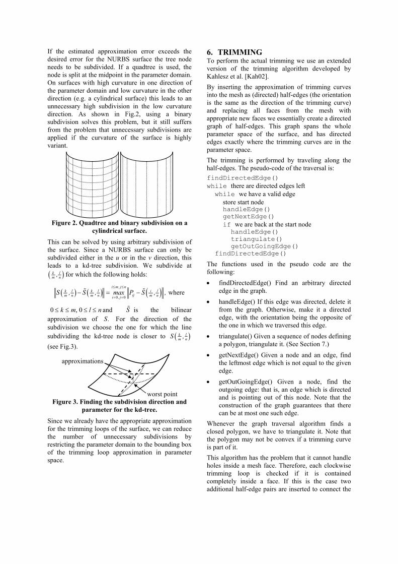
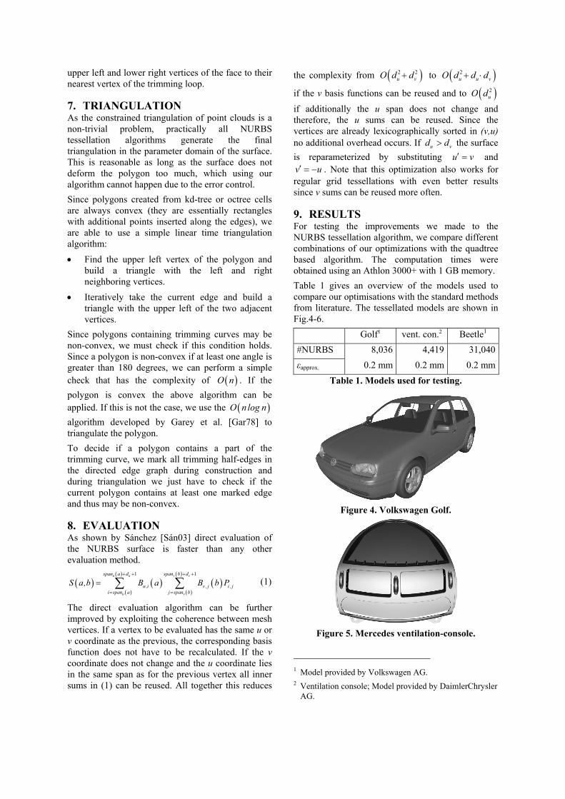
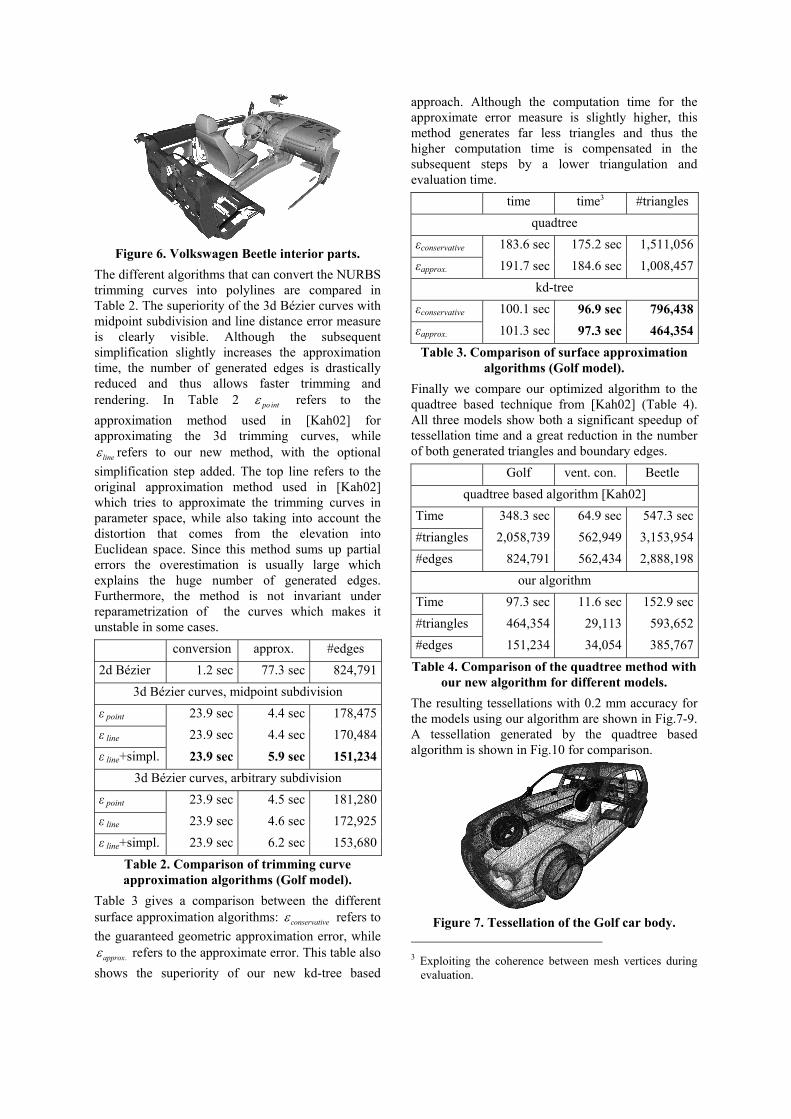
9. RESULTS For testing the improvements we made to the NURBS tessellation algorithm, we compare different combinations of our optimizations with the quadtree based algorithm. The computation times were obtained using an Athlon 3000+ with 1 GB memory. Table 1 gives an overview of the models used to compare our optimisations with the standard methods from literature. The tessellated models are shown in Fig.4-6.
Golf1 vent. con.2 Beetle1
#NURBS 8,036 4,419 31,040εapprox. 0.2 mm 0.2 mm 0.2 mm
Table 1. Models used for testing.
Figure 4. Volkswagen Golf.
Figure 5. Mercedes ventilation-console.
1 Model provided by Volkswagen AG. 2 Ventilation console; Model provided by DaimlerChrysler
AG.
Figure 6. Volkswagen Beetle interior parts.
The different algorithms that can convert the NURBS trimming curves into polylines are compared in Table 2. The superiority of the 3d Bézier curves with midpoint subdivision and line distance error measure is clearly visible. Although the subsequent simplification slightly increases the approximation time, the number of generated edges is drastically reduced and thus allows faster trimming and rendering. In Table 2 po intε refers to the approximation method used in [Kah02] for approximating the 3d trimming curves, while
lineε refers to our new method, with the optional simplification step added. The top line refers to the original approximation method used in [Kah02] which tries to approximate the trimming curves in parameter space, while also taking into account the distortion that comes from the elevation into Euclidean space. Since this method sums up partial errors the overestimation is usually large which explains the huge number of generated edges. Furthermore, the method is not invariant under reparametrization of the curves which makes it unstable in some cases. conversion approx. #edges 2d Bézier 1.2 sec 77.3 sec 824,791
3d Bézier curves, midpoint subdivision ε point 23.9 sec 4.4 sec 178,475ε line 23.9 sec 4.4 sec 170,484ε line+simpl. 23.9 sec 5.9 sec 151,234
3d Bézier curves, arbitrary subdivision ε point 23.9 sec 4.5 sec 181,280ε line 23.9 sec 4.6 sec 172,925ε line+simpl. 23.9 sec 6.2 sec 153,680
Table 2. Comparison of trimming curve approximation algorithms (Golf model).
Table 3 gives a comparison between the different surface approximation algorithms: conservativeε refers to the guaranteed geometric approximation error, while
approx.ε refers to the approximate error. This table also shows the superiority of our new kd-tree based
approach. Although the computation time for the approximate error measure is slightly higher, this method generates far less triangles and thus the higher computation time is compensated in the subsequent steps by a lower triangulation and evaluation time. time time3 #triangles
algorithms (Golf model). Finally we compare our optimized algorithm to the quadtree based technique from [Kah02] (Table 4). All three models show both a significant speedup of tessellation time and a great reduction in the number of both generated triangles and boundary edges. Golf vent. con. Beetle
quadtree based algorithm [Kah02] Time 348.3 sec 64.9 sec 547.3 sec#triangles 2,058,739 562,949 3,153,954#edges 824,791 562,434 2,888,198
Table 4. Comparison of the quadtree method with our new algorithm for different models.
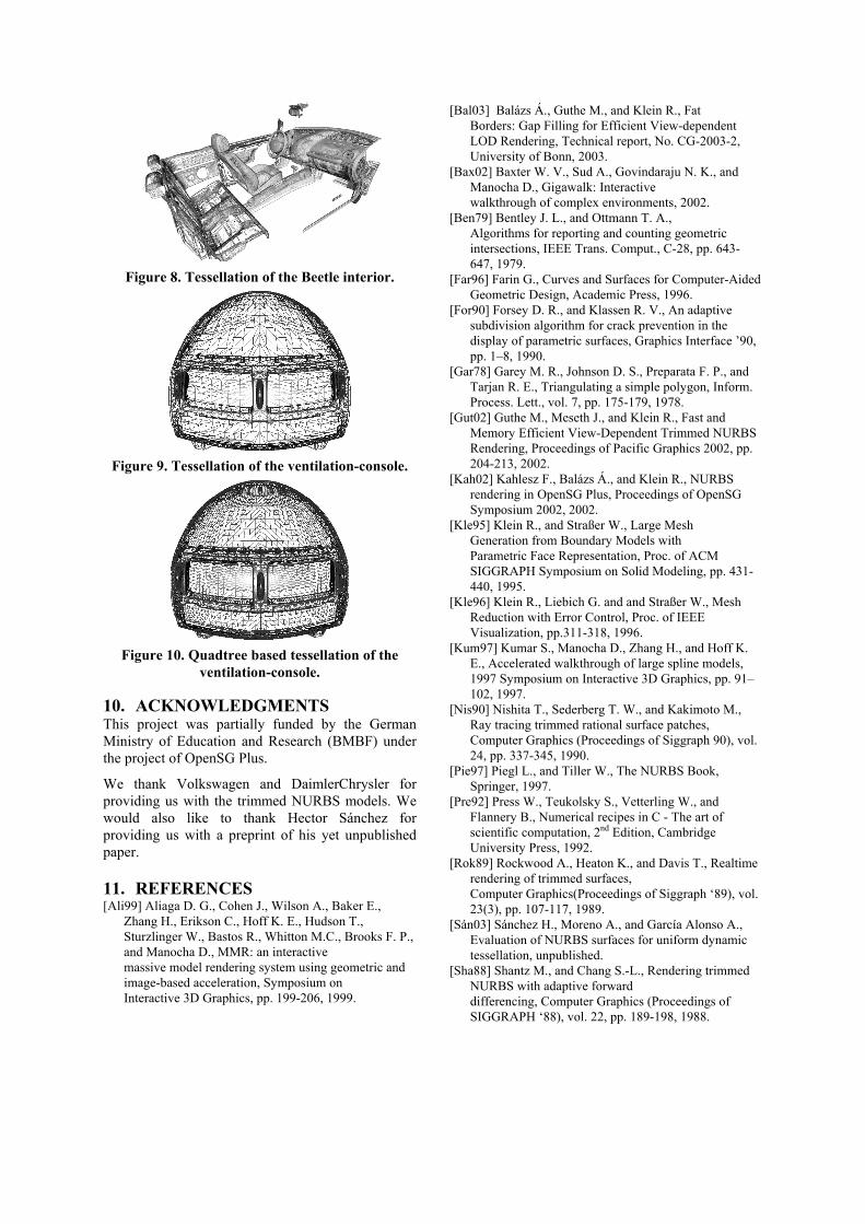
The resulting tessellations with 0.2 mm accuracy for the models using our algorithm are shown in Fig.7-9. A tessellation generated by the quadtree based algorithm is shown in Fig.10 for comparison.
Figure 7. Tessellation of the Golf car body.
3 Exploiting the coherence between mesh vertices during
evaluation.
Figure 8. Tessellation of the Beetle interior.
Figure 9. Tessellation of the ventilation-console.
Figure 10. Quadtree based tessellation of the
ventilation-console.
10. ACKNOWLEDGMENTS This project was partially funded by the German Ministry of Education and Research (BMBF) under the project of OpenSG Plus.
We thank Volkswagen and DaimlerChrysler for providing us with the trimmed NURBS models. We would also like to thank Hector Sánchez for providing us with a preprint of his yet unpublished paper.
11. REFERENCES [Ali99] Aliaga D. G., Cohen J., Wilson A., Baker E.,
Zhang H., Erikson C., Hoff K. E., Hudson T., Sturzlinger W., Bastos R., Whitton M.C., Brooks F. P., and Manocha D., MMR: an interactive massive model rendering system using geometric and image-based acceleration, Symposium on Interactive 3D Graphics, pp. 199-206, 1999.
[Bal03] Balázs Á., Guthe M., and Klein R., Fat Borders: Gap Filling for Efficient View-dependent LOD Rendering, Technical report, No. CG-2003-2, University of Bonn, 2003.
[Bax02] Baxter W. V., Sud A., Govindaraju N. K., and Manocha D., Gigawalk: Interactive walkthrough of complex environments, 2002.
[Ben79] Bentley J. L., and Ottmann T. A., Algorithms for reporting and counting geometric intersections, IEEE Trans. Comput., C-28, pp. 643-647, 1979.
[Far96] Farin G., Curves and Surfaces for Computer-Aided Geometric Design, Academic Press, 1996.
[For90] Forsey D. R., and Klassen R. V., An adaptive subdivision algorithm for crack prevention in the display of parametric surfaces, Graphics Interface ’90, pp. 1–8, 1990.
[Gar78] Garey M. R., Johnson D. S., Preparata F. P., and Tarjan R. E., Triangulating a simple polygon, Inform. Process. Lett., vol. 7, pp. 175-179, 1978.
[Gut02] Guthe M., Meseth J., and Klein R., Fast and Memory Efficient View-Dependent Trimmed NURBS Rendering, Proceedings of Pacific Graphics 2002, pp. 204-213, 2002.
[Kah02] Kahlesz F., Balázs Á., and Klein R., NURBS rendering in OpenSG Plus, Proceedings of OpenSG Symposium 2002, 2002.
[Kle95] Klein R., and Straßer W., Large Mesh Generation from Boundary Models with Parametric Face Representation, Proc. of ACM SIGGRAPH Symposium on Solid Modeling, pp. 431-440, 1995.
[Kle96] Klein R., Liebich G. and and Straßer W., Mesh Reduction with Error Control, Proc. of IEEE Visualization, pp.311-318, 1996.
[Kum97] Kumar S., Manocha D., Zhang H., and Hoff K. E., Accelerated walkthrough of large spline models, 1997 Symposium on Interactive 3D Graphics, pp. 91–102, 1997.
[Nis90] Nishita T., Sederberg T. W., and Kakimoto M., Ray tracing trimmed rational surface patches, Computer Graphics (Proceedings of Siggraph 90), vol. 24, pp. 337-345, 1990.
[Pie97] Piegl L., and Tiller W., The NURBS Book, Springer, 1997.
[Pre92] Press W., Teukolsky S., Vetterling W., and Flannery B., Numerical recipes in C - The art of scientific computation, 2nd Edition, Cambridge University Press, 1992.
[Rok89] Rockwood A., Heaton K., and Davis T., Realtime rendering of trimmed surfaces, Computer Graphics(Proceedings of Siggraph ‘89), vol. 23(3), pp. 107-117, 1989.
[Sán03] Sánchez H., Moreno A., and García Alonso A., Evaluation of NURBS surfaces for uniform dynamic tessellation, unpublished.
[Sha88] Shantz M., and Chang S.-L., Rendering trimmed NURBS with adaptive forward differencing, Computer Graphics (Proceedings of SIGGRAPH ‘88), vol. 22, pp. 189-198, 1988.