30
EFM104HR Wireless Modem Module User’s Manual Hardware revision 1.0

EFM104HRWireless Modem Module
User’s Manual
Hardware revision 1.0

User’s Manual
EFM104HR 2 RTD Finland Oy
EFM104HR56 kbaud Data/Fax Modem Module
User’s Manual
REAL TIME DEVICES FINLAND OYLEPOLANTIE 14
FIN-00660 HELSINKIFINLAND
Phone: (+358) 9 346 4538FAX: (+358) 9 346 4539
Websiteshttp://www.rtdfinland.fi/http://www.rtdusa.com/

User’s Manual
EFM104HR 3 RTD Finland Oy
WARNING
LIFE SUPPORT APPLICATIONS
This product is not designed for use in life support appliances, devices or systemswhere malfunctioning of these products can reasonably be expected to result inpersonal injury. RTD customers using or selling this product for use in theseapplications do so at their own risk and fully agree to indemnify RTD for anydamages resulting from such improper use or sale.
Revision History
13/08/2001 HW Release 1.0, Preliminary version, released
Notice: We have attempted to verify all information in this manual as ofthe publication date. Information in this manual may change without priornotice from RTD Finland Oy.
Published by:Real Time Devices Finland Oy
Lepolantie 14FIN-00660 Helsinki
Finland
Copyright 2001 Real Time Devices Finland OyAll rights reservedPrinted in Finland
PC/XT, PC/AT are registered trademarks of IBM Corporation.PC/104 is a registered trademark of the PC/104 Consortium.
The Real Time Devices Logo is a registered trademark of Real Time Devices.utilityModule is a trademark of Real Time Devices.
MultiModem is a trademark of Multi-Tech Systems Inc.All other trademarks appearing in this document are the property of their respective owners.

User’s Manual
EFM104HR 4 RTD Finland Oy
Table of Contents
List of illustrations and tables ................................5
Chapter 1 Introduction ............................................6Features .................................................................................................. 6Data/Fax modem..................................................................................... 616C550 compatible UART....................................................................... 7I/O interfaces........................................................................................... 7Mechanical description............................................................................ 7Connector description ............................................................................. 7What comes with your board................................................................... 7Using this manual.................................................................................... 8When you need help ............................................................................... 8
Chapter 2 Board settings ........................................9Factory configured jumper settings ....................................................... 10Base address jumpers........................................................................... 11Host interrupt......................................................................................... 13
Chapter 3 Board installation ................................. 14Board installation................................................................................... 14General purpose digital I/O .................................................................. 15
Chapter 4 Hardware description ........................... 17The 56K flex modem module................................................................. 18Phone line connection........................................................................... 18Status LED’s.......................................................................................... 18UART channel ....................................................................................... 19Digital I/O .............................................................................................. 19
Chapter 5 Board operation and programming..... 20Defining the memory map .................................................................... 20BASE+400h Digital I/O.......................................................................... 21BASE+402h EFM104HR status register................................................ 21Interrupts ............................................................................................... 22

User’s Manual
EFM104HR 5 RTD Finland Oy
Chapter 6 EFM104HR Specifications.................... 28
Chapter 7 Return policy and warranty.................. 29
List of illustrations and tables
Fig. 2-1 EFM104HR Board layout showing jumper locations
Fig. 2-2 Base address jumpers illustrating address 3F8h
Fig. 2-3 Interrupt jumpers from left to right: IRQ 2,5,6,7,10,11,12,15 and G
Fig. 3-1 EFM104HR integrated in a RTD PC/104 cpuModule stacktogether with CMM series cpuModule and dataModule
Fig. 3-2 Digital I/O connector layout of the EFM104HR
Fig. 4-1 Block diagram of the EFM104HR
Table 2-1 Factory configured jumper settings
Table 2-2 Base address jumper settings EFM104HR
Table 3-1 Pin outs of the EFM104HR digital I/O interface connector
Table 5-1 General I/O map of the EFM104HR

User’s Manual
EFM104HR 6 RTD Finland Oy
Chapter 1 - INTRODUCTION
This user’s manual describes the operation of the RTD EFM104HR embeddedmodem module designed for industrial, telemetry and security applications.
Features
Some of the key features of the EFM104HR include:
• Low power MT5634SMI-ITP 56K Data/Fax modem• UL 1950, FCC part 68, CS03 and EN60950 approved• 14.4K Class 1 and 2 fax services• Industry standard AT-style commands• 16C550 UART interface to host computer• Supports COM1,COM2,COM3,COM4 or COMx• Available IRQ’s 2,5,6,7,10,11,12,14,15• Status LED’s for DTR,CTS, TXD and RXD• 16 TTL I/O’s 8 outputs, 8 inputs with 10K pull down• +5V only operation, 1W power consumption• Wide operating temperature range –40 to + 85C• Fully PC/104 compliant, IDAN versions available
The following paragraphs briefly describe the major features of the EFM104HR.A more detailed discussion is included in Chapter 4 (Hardware description) Theboards installation is described in Chapter 2 (Board Installation).
Data/Fax modem
The Real Time Devices EFM104HR embedded data and fax modemprovides a direct and reliable connection to proprietary or public wiredtelephone systems for data and/or data connunication. The MTModemModule complies with telecom requirements in the areas of US,Canada and the EU.
The EFM104HR uses the Multi-Tech MT5635SMI-ITP industrialtemperature range modem module. This includes a Lucent Venuscontroller + DSP and the Lucent 1034CSP codec. It also includes a 4MFlash and 32Kx16 SRAM for V.90/K56flex modem operation and V.17Class 1 and Class 2 Fax.
User’s Manual
EFM104HR 7 RTD Finland Oy
16C550 compatible UART
Communication to the ModemModule is performed through a standardUART channel. This onboard serial port leaves the other system serialports free for the user. All operating systems will recognize and supportthis 16C550 standard UART, and therefore no special communicationdrivers are needed to receive data from your modem. Commercial K56flexmodem drivers will work correctly. The address and interrupt of your serialchannel can be changed with the onboard jumpers.
I/O interfaces
The EFM104HR can be controlled and monitored from the softwarethrough two dedicated I/O registers. A special I/O connector is availablefor the user to connect to the general-purpose TTL level digital I/O. Thecontrol registers are located in a I/O area of BASE+400h.
Mechanical description
The EFM104HR is designed on a PC/104 form factor. An easymechanical interface to both PC/104 and RTD IDAN systems can beachieved. Stack your EFM104HR directly on a PC/104 compatible CPUmodule using the onboard mounting holes and standoffs.
Connector description
The Line interface uses a RJ11 standard modem jack interface. Connectyour phone cable directly to this connector, or use a short cable insideyour enclosure to connect to a feed through connector to allow connectionof the antenna to the wall of your enclosure. All general digital I/Oconnections are made using header type terminals.
What comes with your board
Your EFM104HR package contains the following items:
• EFM104HR board• User's manual
Note: Device drivers and example software available on the internet
If any item is missing or damaged, please send an EMAIL to Real TimeDevices Finland sales service department at Internet address:<[email protected]>.
User’s Manual
EFM104HR 8 RTD Finland Oy
Using this manual
This manual is intended to help you install your new EFM104HR moduleand get it working quickly, while also providing enough detail about theboard and it's functions so that you can enjoy maximum use of it's featureseven in the most demanding applications.
When you need help This manual and all the example programs will provide you with enoughinformation to fully utilize all the features on this board. If you have anyproblems installing or using this board, contact our Technical supportdepartment at <[email protected]>. When sending us an Emailrequest please include the following information: Your company's nameand address, your name, your telephone number, and a brief descriptionof the problem.
User’s Manual
EFM104HR 9 RTD Finland Oy
Chapter 2 - BOARD SETTINGS
The EFM104HR board has jumper settings, which can be changed to suityour application and host computer configuration. The factory settings arelisted and shown in the diagram at the beginning of this chapter. Makesure you completely study and understand this chapter before makingchanges to these settings.

User’s Manual
EFM104HR 10 RTD Finland Oy
Factory-Configured Jumper Settings
Table 2-1 below illustrates the factory jumper setting for the EFM104HR.Figure 2-1 shows the board layout of the EFM104HR and the locations ofthe jumpers. The following paragraphs explain how to change the factoryjumper settings to suit your specific application.
Table 2-1 Factory configured jumper settings (Please see figure 2-1 belowfor more detailed locations)
JUMPER NAME DESCRIPTION NUMBER OF JUMPERS FACTORY SETTINGBASE Base Address 6 2E8 / 6E8IRQ Host interrupt 11+1 5, G – jumper closed
Fig. 2-1 EFM104HR Board layout showing jumper locations

User’s Manual
EFM104HR 11 RTD Finland Oy
Base address jumpers (Factory setting: 2E8h, 6E8h)
The EFM104HR is I/O mapped into the memory space of your hostXT/AT. The board occupies a consecutive memory window of 8 bytesstarting from the base address for UART communication and 4consecutive bytes starting from BASE+400h for the board control andstatus registers. As an example if your base address is set to be 2E8h forthe serial port, the onboard control registers will start from 6E8h.
The most common cause of failure when you are first setting up yourmodule is address contention: some of your computers I/O space isalready occupied by other devices and memory resident programs. Whenthe EFM104HR attempts to use it's own reserved memory addresses(which are being already used by another peripheral device) erraticperformance can occur and the data read from the board may becorrupted.
To avoid this problem make sure you set up the base address by usingthe six jumpers on the right side of the board, this allows you to choosefrom a number of different addresses in your host computer’s I/O map.Should the factory installed setting of 38fh be incompatible to your systemconfiguration, you may change this setting to another using the optionsillustrated in Table 2-2 (overleaf). The table shows the jumper settingsand their corresponding values in hexadecimal form. Ensure that youverify the correct location of the base address jumpers. When the jumperis removed it corresponds to a logical "0", connecting the jumper to a "1".When you set the base address of the module, record the setting insidethe back cover of this manual.
User’s Manual
EFM104HR 12 RTD Finland Oy
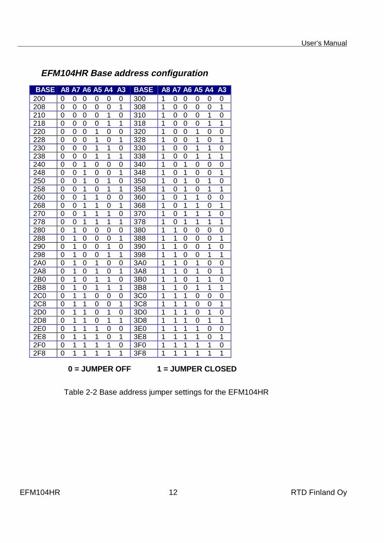
EFM104HR Base address configuration
BASE A8 A7 A6 A5 A4 A3 BASE A8 A7 A6 A5 A4 A3200 0 0 0 0 0 0 300 1 0 0 0 0 0208 0 0 0 0 0 1 308 1 0 0 0 0 1210 0 0 0 0 1 0 310 1 0 0 0 1 0218 0 0 0 0 1 1 318 1 0 0 0 1 1220 0 0 0 1 0 0 320 1 0 0 1 0 0228 0 0 0 1 0 1 328 1 0 0 1 0 1230 0 0 0 1 1 0 330 1 0 0 1 1 0238 0 0 0 1 1 1 338 1 0 0 1 1 1240 0 0 1 0 0 0 340 1 0 1 0 0 0248 0 0 1 0 0 1 348 1 0 1 0 0 1250 0 0 1 0 1 0 350 1 0 1 0 1 0258 0 0 1 0 1 1 358 1 0 1 0 1 1260 0 0 1 1 0 0 360 1 0 1 1 0 0268 0 0 1 1 0 1 368 1 0 1 1 0 1270 0 0 1 1 1 0 370 1 0 1 1 1 0278 0 0 1 1 1 1 378 1 0 1 1 1 1280 0 1 0 0 0 0 380 1 1 0 0 0 0288 0 1 0 0 0 1 388 1 1 0 0 0 1290 0 1 0 0 1 0 390 1 1 0 0 1 0298 0 1 0 0 1 1 398 1 1 0 0 1 12A0 0 1 0 1 0 0 3A0 1 1 0 1 0 02A8 0 1 0 1 0 1 3A8 1 1 0 1 0 12B0 0 1 0 1 1 0 3B0 1 1 0 1 1 02B8 0 1 0 1 1 1 3B8 1 1 0 1 1 12C0 0 1 1 0 0 0 3C0 1 1 1 0 0 02C8 0 1 1 0 0 1 3C8 1 1 1 0 0 12D0 0 1 1 0 1 0 3D0 1 1 1 0 1 02D8 0 1 1 0 1 1 3D8 1 1 1 0 1 12E0 0 1 1 1 0 0 3E0 1 1 1 1 0 02E8 0 1 1 1 0 1 3E8 1 1 1 1 0 12F0 0 1 1 1 1 0 3F0 1 1 1 1 1 02F8 0 1 1 1 1 1 3F8 1 1 1 1 1 1
0 = JUMPER OFF 1 = JUMPER CLOSED
Table 2-2 Base address jumper settings for the EFM104HR

User’s Manual
EFM104HR 13 RTD Finland Oy
Fig. 2-2 Base address jumpers illustrating address 3F8h, A8 is to thebottom, A3 is located to the top of the jumper block
Host interrupt (Factory setting: IRQ5, G closed)
The header connector, shown in Figure 2-3 below, lets you connect theonboard control logic interrupt outputs to one of the interrupt channelsavailable on the host computer XT/AT bus.
Fig. 2-3 Interrupt jumpers from left to right IRQ2,5,6,7,10,11,12,14,15 and G
Note: The EFM104HR hardware supports interrupt sharing! Jumper G must beclosed on one module per used interrupt. For example if two boards shareinterrupt number 7 only one board may have the G jumper closed. The Gjumper connects a 1KOhm resistor to ground while the shared interruptsare 3-stated pulling the line to an inactive level.

User’s Manual
EFM104HR 14 RTD Finland Oy
Chapter 3 BOARD INSTALLATION
The EFM104HR GSM modem module is designed to directly mount on topor under your RTD PC/104 cpuModule stack. This chapter tells you step-by-step how to install your EFM104HR into your system.
Board installation
Keep your board in its antistatic bag until you are ready to install it to yoursystem! When removing it from the bag, hold the board at the edges anddo not touch the components or connectors. Please handle the board inan antistatic environment and use a grounded workbench for testing andhandling of your hardware. Before installing the board in your computer,check the power cabling. Failure to do so may cause the power supplyunit to malfunction or even cause permanent damage.
General installation guidelines:
• Touch the grounded metal housing of your computer to discharge anyantistatic buildup and then remove the board from its antistatic bag.
• Hold the board by the edges and install it in an enclosure or place it onthe table on an antistatic surface
• Install your board in your system, and wire the power supply correctly.Failure to do so may cause the power supply unit to malfunction oreven cause permanent damage to the device.
• Check all wiring connections once and then once more again.• Connect the phone line jack to the RJ11 connector on the EFM104HR
modem.• Apply power to your system.

User’s Manual
EFM104HR 15 RTD Finland Oy
Fig. 3-1 EFM104HR integrated in a RTD PC/104 cpuModule stacktogether with a CMM series cpuModule and dataModule
General Purpose Digital I/O connector
The Table 3-1 below shows the pin outs of the EFM104HR digital I/Ointerface. The signals in this geader connector can be used as generalpurpose TTL level I/O lines to interface to LCD displays, LED’s, pushbuttons or relays. Note that Figure 3-2 shows two connectors together.The connector J2 carries all inputs and J3 carries all the outputs.
PIN J3 Description PIN J3 Description1 +5V 2 Out03 Out1 4 Out25 Out3 6 Out47 Out5 8 Out69 Out7 10 GNDPIN J2 Description PIN J26 Description1 +5V 2 In03 In1 4 In25 In3 6 In47 In5 8 In69 In7 10 GND
Table 3-1 Pin outs of the EFM104HR digital I/O interface connector

User’s Manual
EFM104HR 16 RTD Finland Oy
Fig 3-2 Digital I/O connector layout of the EFM104HR

User’s Manual
EFM104HR 17 RTD Finland Oy
Chapter 4 - HARDWARE DESCRIPTION
This chapter describes the major hardware building blocks of the EFM104HR:
• The 56K flex modem module• Phone line connection• Status LED’s• UART channel• Digital I/O
Fig. 4-1 Block diagram of the EFM104HR

User’s Manual
EFM104HR 18 RTD Finland Oy
The 56K flex modem module
The EFM104HR modem is built around the MultiTech inductrial 56 Kbaudmodem module. It is designed for applications such as telemetry,telematics or communication and for integration in stationary telephonesystems in the EU, the US and Canada.
The EFM104HR is capable of powerful communication with a datarate of56Kbaud. It is capable of FAX communication at 14,4kbaud. TheEFM104HR uses standard modem AT commands with a special extensioninstruction set for modem specif functions. A complete description onthese AT instructions is available in the component specificdocumentation of the MT5634SMI modem unit.
Phone line connection
This section discussed hardware issues related to the phone lineconnection, protection and filtering. Surface mount EMC-filtering ferritesare used on the T&R to reduce emissions on the RJ11 cable. 220pFcapacitors are also used to reduce common mode emissions that may bepresent in certain systems. On the solder side is a blob that must beclosed if the mounting hole next to the high voltage capacitors is notconnected to the chassis groung of your computer.
A special telecom fuse is used in series of the R-line to meet the UL19503’rd edition protection against overvoltage from power line crosses. Allcreepage and clearances of the MT6534SMI and the EFM104HR aredesigned to meet the safety requirements of EN60950 and IEC950.
NOTE: Even if these precautions on the board and the modem moduleare followed, there are no guarantees that a particular installation orsystem will comply with all the necessary regulatory requirements. It isimperative that specific systems are evaluated by a qualified orrecognised agency in you country.
Status LED’s
Four LED’s are used to indicate communication activity. Two green LED’sindicate TXD and RXD line activity while two red LED’s show connectionstatus with DTR and DCD signals.

User’s Manual
EFM104HR 19 RTD Finland Oy
UART channel
Modem data is sent and received through a standard 16C550 compatibleUART. All today’s operating systems will recognize and support this serialcommunication device. The EFM104HR uses its own onboard serial portand will not reserve serial port resources from the system. The I/O baseaddress and interrupt for this serial port can be flexibly set as has beendescribed in previous chapters of this manual. This user’s manual will notwade into details of serial port programming. This information iscommonly available today. You can use any communication softwarepackage or terminal program to connect to your EFM104HR UART. Justmake sure you set up the I/O and IRQ right. The UART on the board isspecified for full operation from –40 to +85C. The oscillator frequency isset to be 1.8432MHz. Note that the UART interrupt can be disabled orenabled from software by writing to bit 01 in address 0x402. After power-up the interrupt is enabled.
Digital I/O
For general-purpose digital I/O interfacing a 16-bit digital I/O port isprovided. This port includes 8 TTL-level digital outputs that areautomatically cleared (to 0) after system reset. Also are included 8 digitalinputs with 10K Ohm pull-down resistors. These I/O’s are located on theleft side of the board. These I/O’s are ideal to be used to interface to LCDdisplays, LED’s push buttons or other low power controls.

User’s Manual
EFM104HR 20 RTD Finland Oy
Chapter 5 BOARD OPERATION AND PROGRAMMING
This chapter shows you how to program and use your EFM104HR. Itprovides a general description of the I/O map. Detailed serial portprogramming tips are not within the scope of this manual.
Defining the Memory Map
The memory map of the EFM104HR occupies eight bytes of host PC I/Ospace. This window is freely selectable by the user as described inChapter 2, Table 2-2. After setting the base address you have access tothe internal resources of the EFM104HR control logic. These resourcesare not described in detail, since they are mapped as a standard PC serialport. For more details on the EXAR ST16C550IJ44 UART chipprogramming please download the component specific data sheet fromthe manufacturers website: http://www.exar.com/products/st16c550.html
ADDR (hex) REGISTER DIR COMMENTS
TXD O Only if control reg. Bit 7=0
RXD I Only if control reg. Bit 7=0
BASE
BAUD div. Low Only if control reg. Bit 7=1
BAUD div. High Only if control reg. Bit 7=1BASE+1
IRQ enable Only if control reg. Bit 7=0
BASE+2 IRQ ID
BASE+3 Line control
BASE+4 Modem control
BASE+5 Line status
BASE+6 Modem status
BASE+400 Digital I/O I/O Digital I/O ports
BASE+402 EFM104HRstatus
I/O Configuration registers
BASE+403 EFM104HRcontrol
I/O Reserved for future use
Table 5-1 General I/O map of the EFM104HR, BASE = Base Address

User’s Manual
EFM104HR 21 RTD Finland Oy
BASE+400 Digital I/O (R/W)
This address is used to interface to the digital I/O port of theEFM104HR, writing to this address will transfer the data out of the outputport, while reading from this address will return the data from the digitalinputs.
BASE+402 EFM104HR Status (R/W, 0x00 after reset)
Write
Bit 0 /EN_RST 0 - host reset will clear digital outputs; 1 - disabledBit 1 /EN_INT 0 – UART interrupt enabled; 1 - disabledBit 2 RESERVEDBit 3 RESERVED
Read
Bit 0 /EN_RST stateBit 1 /EN_INT stateBit 2 RESERVEDBit 3 RESERVED
BASE+403 EFM104HR Control (R/W, 0x00 after reset)
Write
Bit 0 RESERVEDBit 1 RESERVEDBit 2 RESERVEDBit 3 RESERVED
Read
Bit 0 RESERVEDBit 1 RESERVEDBit 2 RESERVEDBit 3 RESERVED

User’s Manual
EFM104HR 22 RTD Finland Oy
INTERRUPTS
What is an interrupt?
An interrupt is an event that causes the processor in your computer totemporarily halt its current process and execute another routine. Uponcompletion of the new routine, control is returned to the original routine atthe point where its execution was interrupted.
Interrupts are a very flexible way of dealing with asynchronous events.Keyboard activity is a good example; your computer cannot predict whenyou might press a key and it would be a waste of processor time to donothing whilst waiting for a keystroke to occur. Thus the interrupt schemeis used and the processor proceeds with other tasks. When a keystrokefinally occurs, the keyboard then 'interrupts' the processor so that it canget the keyboard data. It then places it into the memory, and then returnsto what it was doing before the interrupt occurred. Other common devicesthat use interrupts are A/D boards, network boards, other used serialports etc.
Interrupt request lines
To allow different peripheral devices to generate interrupts on the samecomputer, the PC AT bus has interrupt request channels (IRQ's). A risingedge transition on one of these lines will be latched into the interruptcontroller. The interrupt controller checks to see if the interrupts are to beacknowledged from that IRQ and, if another interrupt is being processed,it decides if the new request should supercede the one in progress or if ithas to wait until the one in progress has been completed. The prioritylevel of the interrupt is determined by the number of the IRQ as follows;IRQ0 has the highest priority whilst IRQ15 has the lowest. Many of theIRQ's are already used by the standard system resources, IRQ0 isdedicated to the internal timer, IRQ1 is dedicated to the keyboard input,IRQ3 for the serial port COM2, and IRQ4 for the serial port COM1. Ofteninterrupts 2,5,7,10,11 and 15 are free for the user.

User’s Manual
EFM104HR 23 RTD Finland Oy
8259 Programmable Interrupt Controller
The chip responsible for handling interrupt requests in a PC is the 8259Interrupt Controller. To use interrupts you will need to know how to readand set the 8259's internal interrupt mask register (IMR) and how to sendthe end-of-interrupt (EOI) command to acknowledge the 8259 interruptcontroller.
Interrupt Mask Register (IMR)
Each bit in the interrupt mask register (IMR) contains the mask status ofthe interrupt line. If a bit is set (equal to 1), then the corresponding IRQ ismasked, and it will not generate an interrupt. If a bit is cleared (equal to0), then the corresponding IRQ is not masked, and it can then generatean interrupt. The interrupt mask register is programmed through port 21h .
End-of-Interrupt (EOI) Command
After an interrupt service routine is complete, the 8259 Interrupt Controllermust be acknowledged by writing the value 20h to port 20h.
What exactly happens when an interrupt occurs?
Understanding the sequence of events when an interrupt is triggered isnecessary to correctly write interrupt handlers. When an interrupt requestline is driven high by a peripheral device (such as the EFM104HR), theinterrupt controller checks to see if interrupts are enabled for that IRQ. Itthen checks to see if other interrupts are active or requested anddetermines which interrupt has priority. The interrupt controller theninterrupts the processor. The current code segment (CS), instructionpointer (IP), and flags are pushed onto the system stack, and a new set ifCS and IP are loaded from the lowest 1024 bytes of memory.
This table is referred to as the interrupt vector table and each entry to thistable is called an interrupt vector. Once the new CS and IP are loadedfrom the interrupt vector table, the processor starts to execute code fromthe new Code Segment (CS) and from the new Instruction Pointer (IP).When the interrupt routine is completed, the old CS and IP are poppedfrom the system stack and the program execution continues from the pointwhere interruption occurred.

User’s Manual
EFM104HR 24 RTD Finland Oy
Using Interrupts in your Program
Adding interrupt support to your program is not as difficult as it may seemespecially when programming under DOS. The following discussion willcover programming under DOS. Note that even the smallest mistake inyour interrupt program may cause the computer to hang up and will onlyrestart after a reboot. This can be frustrating and time-consuming.
Writing an Interrupt Service Routine (ISR)
The first step in adding interrupts to your software is to write an interruptservice routine (ISR). This is the routine that will be executedautomatically each time an interrupt request occurs for the specified IRQ.An ISR is different from other sub-routines or procedures. First onentrance the processor registers must be pushed onto the stack beforeanything else! Second, just before exiting the routine, you must clear theinterrupt on the EFM104HR by writing to the Status register, and write theEOI command to the interrupt controller. Finally, when exiting the interruptroutine the processor registers must be popped from the system stack andyou must execute the IRET assembly instruction. This instruction pops theCS, IP and processor flags from the system stack. These were pushedonto the stack when entering the ISR.
Most compilers allow you to identify a function as an interrupt type and willautomatically add these instructions to your ISR with one exception: mostcompilers do not automatically add the EOI command to the function, youmust do it yourself. Other than this and a few exceptions discussed below,you can write your ISR as any code routine. It can call other functions andprocedures in your program and it can access global data. If you arewriting your first ISR, we recommend you stick to the basics; justsomething that enables you to verify you have entered the ISR andexecuted it successfully. For example: set a flag in your ISR and in yourmain program check for the flag.
Note: If you choose to write your ISR in in-line Assembly, you must pushand pop registers correctly and exit the routine with the IRETinstruction instead of the RET instruction.
There are a few precautions you must consider when writing ISR's. Themost important is, do not use any DOS functions or functions that callDOS functions from an interrupt routine. DOS is not re-entrant; that is, aDOS function cannot call itself. In typical programming, this will not happenbecause of the way DOS is written. But what about using interrupts?Consider then the following situation in your program: If DOS function X is

User’s Manual
EFM104HR 25 RTD Finland Oy
being executed when an interrupt occurs and the interrupt routine makes acall to the same DOS function X, then function X is essentially being calledwhile active. Such cases will cause the computer to crash. DOS does notsupport such operations. The general rule is that do not call any functionsthat use the screen, read keyboard input or any file I/O routines, theseshould not be used in ISR's.
The same problem of re-entrancy also exists for many floating-pointemulators. This effectively means that you should also avoid floating pointmathematical operations in your ISR.
Note that the problem of reentrancy exists, no matter what programminglanguage you use. Even, if you are writing your ISR in Assembly language,DOS and many floating point emulators are not re-entrant. Of course thereare ways to avoid this problem, such as those which activate when yourISR is called. Such solutions are, however, beyond the scope of thismanual.
The second major concern when writing ISR's is to make them as short aspossible in term of execution time. Spending long times in interrupt serviceroutines may mean that other important interrupts are not serviced. Also, ifyou spend too long in your ISR, it may be called again before you haveexited. This will lead to your computer hanging up and will require a reboot.
Your ISR should have the following structure:
• Push any processor registers used in your ISR.• Put the body of your routine here• Clear the interrupt bit by reading EFM104HR RXD register• Issue the EOI command to the 8259 by writing 20h to 20h• Pop all registers. Most C compilers do this automatically
The following C example shows what the shell of your ISR should be like:
void interrupt far new_IRQ_handler(void){
IRQ_flag = 1; // Indicate to process interrupt has occurred
{// Your program code to read UART// read to a data buffer for example:
Guc_buffer[Gi_bufpos++] = inp(gi_SERIAL_DATA);}
outp(0x20, 0x20); // Acknowledge the interrupt controller}

User’s Manual
EFM104HR 26 RTD Finland Oy
Saving the Startup Interrupt Mask Register (IMR) and interrupt vector
The next step after writing the ISR is to save the startup-state of theinterrupt mask register, (IMR) and the original interrupt vector you areusing. The IMR is located in address 21h. The interrupt vector you will beusing is located in the interrupt vector table which is an array of pointers(addresses) and it is locate din the first 1024 bytes of the memory(Segment 0 offset 0). You can read this value directly, but it is betterpractice to use DOS function 35h (get interrupt vector) to do this. Most Ccompilers have a special function available for doing this. The vectors forthe hardware interrupts on the XT - bus are vectors 8-15, where IRQ0 usesvector 8 and IRQ7 uses vector 15. Thus if your EFM104HR is using IRQ5 itcorresponds to vector number 13.
Before you install your ISR, temporarily mask out the IRQ you will be using.This prevents the IRQ from requesting an interrupt while you are installingand initializing your ISR. To mask the IRQ, read the current IMR at I/O port21h, and set the bit that corresponds to the IRQ. The IMR is arranged sothat bit 0 is for IRQ0 and bit 7 is for IRQ7. See the paragraph entitledInterrupt Mask Register (IMR) earlier in this discussion for help indetermining your IRQ's bit. After setting the bit, write the new value to I/Oport 21h.
With the startup IMR saved and the interrupts temporarily disabled, youcan assign the interrupt vector to point to your ISR. Again you canoverwrite the appropriate entry in the vector table with a direct memorywrite, but this is not recommended. Instead use the DOS function 25h (SetInterrupt Vector) or, if your compiler provides it, the library routine forsetting up interrupt vectors. Remember that interrupt vector 8 correspondsto IRQ0, vector 9 for IRQ1 etc.
If you need to program the source of your interrupts, do that next. Forexample, if you are using transmitted or received messages as an interruptsource program it to do that. Finally, clear the mask bit for your IRQ in theIMR. This will enable your IRQ.
Common Interrupt mistakes
Remember hardware interrupts are from 8-15, XT IRQ's are numbered 0-7.Do not forget to clear the IRQ mask bit in the IMR Forgetting to send theEOI command after ISR code. Disables further interrupts.

User’s Manual
EFM104HR 27 RTD Finland Oy
Example on Interrupt vector table setup in C-code:
void far _interrupt new_IRQ1_handler(void ); /* ISR function */#define IRQ1_VECTOR 3 /* Name for IRQ */void (interrupt far *old_IRQ1_dispatcher)
(es,ds,di,si,bp,sp,bx,dx,cx,ax,ip,cs,flags); /* Variable to storeold IRQ_Vector */void far _interrupt new_IRQ1_handler(void );
/*----------------------------------------------------------------------| Function: init_irq_handlers| Inputs: Nothing| Returns: Nothing| Purpose: Set the pointers in the interrupt table to point to| our funtions ie. setup for ISR's.|----------------------------------------------------------------------*/void init_irq_handlers(void){
_disable();old_IRQ1_handler = _dos_getvect(IRQ1_VECTOR + 8);_dos_setvect(IRQ1_VECTOR + 8, new_IRQ1_handler);Gi_old_mask = inp(0x21);outp(0x21,Gi_old_mask & ~(1 << IRQ1_VECTOR));
_enable();}
|/*----------------------------------------------------------------------| Function: restore, do this before exiting program| Inputs: Nothing| Returns: Nothing| Purpose: Restore the interrupt vector table.|----------------------------------------------------------------------*/void restore(void){
/* Restore the old vectors */_disable();
_dos_setvect(IRQ1_VECTOR + 8, old_IRQ1_handler);outp(0x21,Gi_old_mask);
_enable();}

User’s Manual
EFM104HR 28 RTD Finland Oy
Chapter 6 - EFM104HR SPECIFICATIONS
Host interface
16-bit PC/104 bus, XT-bus used for data
Modem specifications
OperationalClient-to-Server V.90 or K56 flex 56Kbps download speed,
upload speed 33,6Kbps via enhanced V.34Client-to-Client 33,600, 31,200, 28,800, 24,00, 21,600, 19,200,
16,800,14,400, 12,00, 9600, 7200, 4800, 2400,1200, 0-300bps
Fax datarates 14,400, 12,00, 9600, 7200, 4800, 2400, 1200,300bps
Data format Serial, binary, asyncronousModem compatibility ITU V.90, K56flexStatus indicator 4 LED’s
UART and I/O
UART compatibility 16C550Oscillator frequency 1.8432MHzConnection Full hardware handshaking supportedBase addresses 32+4Interrupts 2,5,7,10,11,12,14 and 15Digital I/O 8 TTL outputs, 8 TTL inputs w. 10K pd.
EFM104HR Electromechanical
Operating temperature range -40 to +85C, Convection coolingHumidity RH up to 95% non condensingAltitude -1000 to 30.000 ftVibration Survival 10G peakPower consumption 0.8W min; 1.2W normal

User’s Manual
EFM104HR 29 RTD Finland Oy
Chapter 7 - RETURN POLICY AND WARRANTY
Return PolicyIf the module requires repair, you may return it to us by following the procedure listedbelow:
Caution: Failure to follow this return procedure will almost always delay repair! Please helpus expedite your repair by following this procedure.
1) Read the limited warranty, which follows.
2) Contact the factory and request a Returned Merchandise Authorization (RMA) number.
3) On a sheet of paper, write the name, phone number, and fax number of a technicallycompetent person who can answer questions about the problem.
4) On the paper, write a detailed description of the problem with the product. Answer thefollowing questions:
• Did the product ever work in your application?• What other devices were connected to the product?• How was power supplied to the product?• What features did and did not work?• What was being done when the product failed?• What were environmental conditions when the product failed?
5) Indicate the method we should use to ship the product back to you.
• We will return warranty repairs by UPS Ground at our expense.• Warranty repairs may be returned by a faster service at your expense.• Non-warranty repairs will be returned by UPS Ground or the method you select, and
will be billed to you.
6) Clearly specify the address to which we should return the product when repaired.
7) Enclose the paper with the product being returned.
8) Carefully package the product to be returned using anti-static packaging! We will notbe responsible for products damaged in transit for repair.
7) Write the RMA number on the outside of the package.
8) Ship the package to:
Real Time Devices Finland Oy
Lepolantie 14
FIN-00660 Helsinki
FINLAND

User’s Manual
EFM104HR 30 RTD Finland Oy
Limited WarrantyReal Time Devices, Inc. warrants the hardware and software products it manufacturesand produces to be free from defects in materials and workmanship for one year followingthe date of shipment from REAL TIME DEVICES. This warranty is limited to the originalpurchaser of product and is not transferable.
During the one year warranty period, REAL TIME DEVICES will repair or replace, at itsoption, any defective products or parts at no additional charge, provided that the productis returned, shipping prepaid, to REAL TIME DEVICES. All replaced parts and productsbecome the property of REAL TIME DEVICES. Before returning any product for repair,customers are required to contact the factory for an RMA number.
THIS LIMITED WARRANTY DOES NOT EXTEND TO ANY PRODUCTS WHICH HAVEBEEN DAMAGED AS A RESULT OF ACCIDENT, MISUSE, ABUSE (such as: use ofincorrect input voltages, improper or insufficient ventilation, failure to follow the operatinginstructions that are provided by REAL TIME DEVICES, "acts of God" or othercontingencies beyond the control of REAL TIME DEVICES), OR AS A RESULT OFSERVICE OR MODIFICATION BY ANYONE OTHER THAN REAL TIME DEVICES.EXCEPT AS EXPRESSLY SET FORTH ABOVE, NO OTHER WARRANTIES AREEXPRESSED OR IMPLIED, INCLUDING, BUT NOT LIMITED TO, ANY IMPLIEDWARRANTIES OF MERCHANTABILITY AND FITNESS FOR A PARTICULARPURPOSE, AND REAL TIME DEVICES EXPRESSLY DISCLAIMS ALL WARRANTIESNOT STATED HEREIN. ALL IMPLIED WARRANTIES, INCLUDING IMPLIEDWARRANTIES FOR MECHANTABILITY AND FITNESS FOR A PARTICULARPURPOSE, ARE LIMITED TO THE DURATION OF THIS WARRANTY. IN THE EVENTTHE PRODUCT IS NOT FREE FROM DEFECTS AS WARRANTED ABOVE, THEPURCHASER'S SOLE REMEDY SHALL BE REPAIR OR REPLACEMENT ASPROVIDED ABOVE. UNDER NO CIRCUMSTANCES WILL REAL TIME DEVICES BELIABLE TO THE PURCHASER OR ANY USER FOR ANY DAMAGES, INCLUDING ANYINCIDENTAL OR CONSEQUENTIAL DAMAGES, EXPENSES, LOST PROFITS, LOSTSAVINGS, OR OTHER DAMAGES ARISING OUT OF THE USE OR INABILITY TO USETHE PRODUCT.
SOME STATES DO NOT ALLOW THE EXCLUSION OR LIMITATION OF INCIDENTALOR CONSEQUENTIAL DAMAGES FOR CONSUMER PRODUCTS, AND SOMESTATES DO NOT ALLOW LIMITATIONS ON HOW LONG AN IMPLIED WARRANTYLASTS, SO THE ABOVE LIMITATIONS OR EXCLUSIONS MAY NOT APPLY TO YOU.
THIS WARRANTY GIVES YOU SPECIFIC LEGAL RIGHTS, AND YOU MAY ALSOHAVE OTHER RIGHTS, WHICH VARY FROM STATE TO STATE.


