177
EFS 50 Pilot’s Guide 5-inch Electronic Flight Instrumentation System A
| Date post: | 29-Nov-2015 |
| Category: |
Documents |
| Upload: | himanshu-haldar |
| View: | 42 times |
| Download: | 2 times |

EFS 50Pilot’s Guide
5-inch Electronic FlightInstrumentation System
BAlliedSignal General Aviation Avionics400 North Rogers RoadOlathe, Kansas 66062-1212TELEX 669916 KINGRAD FAX 913-791-1302TELEPHONE (913) 768-3000
©1995 AlliedSignal Inc.4/95 006-08485-0000 1K PRINTED IN THE U.S.A.SW 06/07/08/11
AA

Registration
This pilot's guide has been tailored by the installation and or certifica-tion agency to cover the following EFS 50 installation:
AIRCRAFT TYPE
AIRCRAFT TAIL OR SERIAL NUMBER
AIRCRAFT OWNER
EFIS TYPE
EFIS SYSTEM CONFIGURATION
EFIS SYSTEM SOFTWARE LEVEL
EFIS DISPLAY UNIT TYPE
EFIS CONTROL PANELS
REVERSIONARY MODES
Throughout this pilot's guide various configuration options aredescribed. A ✔❏ (check box) precedes each configuration option. Acheck mark may be placed in the appropriate boxes to define whichconfiguration options are available in a given installation.

Registration
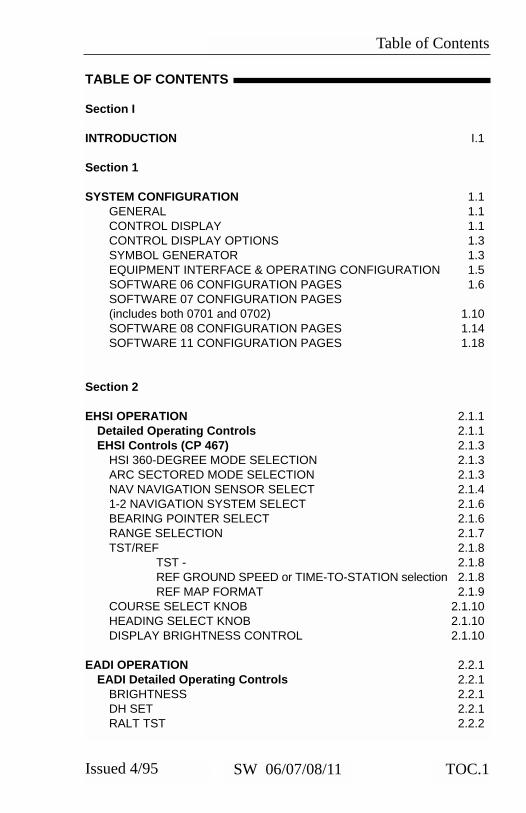
Table of Contents
TOC.1Issued 4/95 SW 06/07/08/11
TABLE OF CONTENTS
Section I
INTRODUCTION I.1
Section 1
SYSTEM CONFIGURATION 1.1GENERAL 1.1CONTROL DISPLAY 1.1CONTROL DISPLAY OPTIONS 1.3SYMBOL GENERATOR 1.3EQUIPMENT INTERFACE & OPERATING CONFIGURATION 1.5SOFTWARE 06 CONFIGURATION PAGES 1.6SOFTWARE 07 CONFIGURATION PAGES (includes both 0701 and 0702) 1.10SOFTWARE 08 CONFIGURATION PAGES 1.14SOFTWARE 11 CONFIGURATION PAGES 1.18
Section 2
EHSI OPERATION 2.1.1Detailed Operating Controls 2.1.1EHSI Controls (CP 467) 2.1.3
HSI 360-DEGREE MODE SELECTION 2.1.3ARC SECTORED MODE SELECTION 2.1.3NAV NAVIGATION SENSOR SELECT 2.1.41-2 NAVIGATION SYSTEM SELECT 2.1.6BEARING POINTER SELECT 2.1.6RANGE SELECTION 2.1.7TST/REF 2.1.8
TST - 2.1.8REF GROUND SPEED or TIME-TO-STATION selection 2.1.8REF MAP FORMAT 2.1.9
COURSE SELECT KNOB 2.1.10HEADING SELECT KNOB 2.1.10DISPLAY BRIGHTNESS CONTROL 2.1.10
EADI OPERATION 2.2.1 EADI Detailed Operating Controls 2.2.1
BRIGHTNESS 2.2.1DH SET 2.2.1RALT TST 2.2.2

Table of Contents
TOC.2 Issued 4/95SW 06/07/08/11
RADAR OPERATION 2.3.1Radar Controls, (CP 466A & CP 466B) 2.3.3
OFF-STBY-TST-ON 2.3.4OFF 2.3.4STBY 2.3.4TST 2.3.4ON 2.3.4
WX 2.3.4WXA 2.3.4GND MAP 2.3.4LIGHTNING 2.3.5VP 2.3.5TRK 2.3.6GAIN 2.3.7PULL ARL 2.3.7TILT 2.3.7
MFD OPERATION 2.4.1Multi Function Display Control Panel 2.4.1Control Panel Button Operations 2.4.2
TCAS ONLY BUTTON 2.4.2HSI BUTTON 2.4.2ARC BUTTON 2.4.2ENT BUTTON 2.4.2
LNAV MAP 2.4.2PLAN-VIEW MAP (available with software 07) 2.4.2CHECKLIST (available with software 08) 2.4.2
NAV BUTTON 2.4.3RANGE UP/DOWN BUTTONS 2.4.3CHECKLIST BUTTON 2.4.3COURSE SELECT KNOB/BUTTON 2.4.3BEARING #1 & #2 BUTTON 2.4.4JOYSTICK 2.4.4
LNAV MAP 2.4.4PLAN-VIEW MAP 2.4.5CHECKLIST MODE (available with software 08) 2.4.6
1-2 BUTTON 2.4.6TST/REF BUTTON 2.4.7
Section 3
ABBREVIATED OPERATIONS 3.1

Table of Contents
TOC.3Issued 4/95 SW 06/07/08/11
Section 4
EHSI DISPLAYS 4.1.1EFS 50 Color Standards 4.1.1Standard EHSI Displays 4.1.1
NORMAL COMPASS CARD 4.1.1NAVIGATION SOURCE ANNUNCIATION 4.1.2SYMBOLIC AIRCRAFT 4.1.3HEADING SELECT “BUG” 4.1.3COURSE SELECT 4.1.3LATERAL COURSE DEVIATION SCALE 4.1.4LATERAL COURSE DEVIATION BAR 4.1.4TO/FROM INDICATOR 4.1.5DISTANCE, GROUNDSPEED and TIME-TO-STATION 4.1.5DUAL MULTI CHANNEL DME INSTALLATION 4.1.6DME HOLD 4.1.7BEARING POINTER 4.1.8MAGNETIC/TRUE HEADING ANNUNCIATIONS 4.1.10GLIDE SLOPE/VERTICAL NAVIGATION 4.1.10WIND VECTOR 4.1.12DRIFT ANGLE POINTER (LNAV only) 4.1.12LNAV MODE ANNUNCIATIONS 4.1.12
360 Map Displays 4.1.13MAP 360 COMPASS CARD 4.1.13SELECTED COURSE 4.1.13MAP COURSE DEVIATION INDICATOR 4.1.14TO/FROM 4.1.14BEARING POINTER 4.1.14REFERENCE WAYPOINT 4.1.15RANGE RING 4.1.16360-DEGREE MAP WX RADAR (IF EQUIPPED) 4.1.16
TRACK LINE 4.1.17LIGHTNING DETECTION 4.1.17FULL TIME LNAV MAP 4.1.18
ARC (Expanded Sectored Mode) Displays 4.1.20HDG BUG (ALL ARC FORMAT MODES) 4.1.20COURSE DEVIATION INDICATOR 4.1.20(EHSI ARC NON-MAP FORMAT)
EADI DISPLAYS 4.2.1Normal Attitude Display 4.2.1
PITCH ATTITUDE 4.2.1ROLL ATTITUDE 4.2.1ROLL INDICATOR 4.2.1
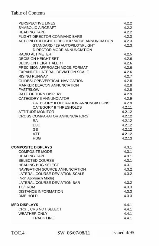
Table of Contents
TOC.4 Issued 4/95SW 06/07/08/11
PERSPECTIVE LINES 4.2.2SYMBOLIC AIRCRAFT 4.2.2HEADING TAPE 4.2.2FLIGHT DIRECTOR COMMAND BARS 4.2.3AUTOPILOT/FLIGHT DIRECTOR MODE ANNUNCIATION 4.2.3
STANDARD 429 AUTOPILOT/FLIGHT 4.2.3DIRECTOR MODE ANNUNCIATION
RADIO ALTIMETER 4.2.5DECISION HEIGHT SET 4.2.6DECISION HEIGHT ALERT 4.2.6PRECISION APPROACH MODE FORMAT 4.2.6EXPANDED LATERAL DEVIATION SCALE 4.2.6RISING RUNWAY 4.2.7GLIDESLOPE/VERTICAL NAVIGATION 4.2.8MARKER BEACON ANNUNCIATION 4.2.8FAST/SLOW 4.2.8RATE OF TURN DISPLAY 4.2.9CATEGORY II ANNUNCIATOR 4.2.9
CATEGORY II OPERATION ANNUNCIATIONS 4.2.9CATEGORY II THRESHOLDS 4.2.11
ATTITUDE MONITOR 4.2.12CROSS COMPARATOR ANNUNCIATORS 4.2.12
RA 4.2.12LOC 4.2.12GS 4.2.12ATT 4.2.12HDG 4.2.13
COMPOSITE DISPLAYS 4.3.1COMPOSITE MODE 4.3.1HEADING TAPE 4.3.1SELECTED COURSE 4.3.1HEADING BUG SELECT 4.3.1NAVIGATION SOURCE ANNUNCIATION 4.3.2LATERAL COURSE DEVIATION SCALE 4.3.2(Non Approach Mode) LATERAL COURSE DEVIATION BAR 4.3.2TO/FROM 4.3.3DISTANCE INFORMATION 4.3.3DME HOLD 4.3.3
MFD DISPLAYS 4.4.1CRS , CRS NOT SELECT 4.4.1WEATHER ONLY 4.4.1
TRACK LINE 4.4.1

Table of Contents
TOC.5Issued 4/95 SW 06/07/08/11
VERTICAL PROFILE (VP) 4.4.1SYMBOLIC AIRCRAFT 4.4.1RANGE RINGS 4.4.1ALTITUDE LINE 4.4.2PROFILE ANGLE 4.4.2PLAN-VIEW, NORTH-UP MAP 4.4.2
TCAS INTERFACE 4.4.3TCAS ONLY SELECTION 4.4.3TCAS DISPLAY FORMAT 4.4.4TCAS TRAFFIC SYMBOLOGY 4.4.4
Intruder Symbols 4.4.4Vertical Speed Arrow 4.4.4Data Tag 4.4.4Off-Scale Traffic 4.4.5
TCAS DISPLAY ANNUNCIATIONS 4.4.5Traffic 4.4.5TCAS 4.4.5TCAS Status 4.4.6TCAS Mode 4.4.6Range 4.4.7Range Rings 4.4.7Above/Norm/Below 4.4.7No-Bearing Traffic 4.4.7FLXXX and FL 4.4.7Weather/Lightning Annunciation 4.4.8
CHECKLIST INTERFACE 4.4.8LOADING AND MODIFYING CHECKLIST DATA 4.4.8NOTICE 4.4.8CHECKLIST PAGE ORGANIZATION 4.4.9ROOT INDEX PAGE 4.4.9SUB INDEX PAGES 4.4.10CHECKLIST ITEM PAGES 4.4.10NOTE PAGES 4.4.11CLEARING CHECKLIST ITEMS 4.4.11EMERGENCY PAGE ACTIVATION 4.4.11CHECKLIST CONTROLS 4.4.12
Checklist: CHKLIST 4.4.12Joystick 4.4.13Enter : ENT 4.4.13HSI 4.4.14ARC 4.4.14NAV 4.4.14Up Arrow 4.4.14Down Arrow 4.4.141-2 4.4.15

Table of Contents
TOC.6 Issued 4/95SW 06/07/08/11
RMI 1 4.4.15RMI 2 4.4.15CRS(NOT) SEL 4.4.15TST REF 4.4.15CRS Knob 4.4.15
Section 5
OPERATING INSTRUCTIONS 5.1PREFLIGHT PROCEDURES 5.1
START UP 5.1SELF TEST 5.1PUSH BUTTON TEST 5.1
PRE-TAKEOFF PROCEDURES 5.1IN-FLIGHT OPERATION 5.2
ADF 5.2LNAV (RNAV) 5.2VNAV 5.3
APPROACH PROCEDURES 5.3ILS APPROACH 5.3BACK COURSE APPROACH 5.3ADF APPROACH 5.4LNAV (RNAV) APPROACH 5.4VOR APPROACH 5.4DECISION HEIGHT SELECTION 5.4
LIMITATIONS 5.5EMERGENCY PROCEDURES 5.5
Section 6
FAULT ANNUNCIATIONS 6.1General 6.1
EXTERNAL SYSTEM FAILURES 6.1HEADING 6.1ATTITUDE 6.1FLIGHT DIRECTOR 6.1
EFS 50 SYSTEM FAILURES 6.1DU—DISPLAY UNIT LOSS OF COOLING 6.1SG—SYMBOL GENERATOR LOSS OF COOLING 6.1CP—CONTROL PANEL (CP 467 OR CP 469/A) 6.2 HEADING SELECT “BUG” 6.2COURSE SELECT 6.2RCP—RADAR CONTROL PANEL (if equipped) 6.2SG—SYMBOL GENERATOR 6.3
RAW DATA DEVIATION ANNUNCIATIONS 6.3

Table of Contents
TOC.7Issued 4/95 SW 06/07/08/11
BEARING POINTER ANNUNCIATIONS 6.3ALPHANUMERIC READOUT ANNUNCIATIONS 6.3CHECK CONFIG 6.4
WEATHER RADAR ANNUNCIATIONS 6.4WX FLT 6.4WX OFF 6.4BUSY VP 6.4STB LMT 6.4429 FLT 6.4ANT FLT 6.4TX FLT 6.4RANGE 6.4STB OFF 6.5WAIT 6.5TCAS FAULT MESSAGES 6.5FAULT MESSAGES 6.5
Section 7
REVERSIONARY MODES 7.1CMPST - COMPOSITE 7.2DISPLAY (EADI) DOWN 7.3SG 3 7.4
Section 8
GLOSSARY 8.1
Section 9
INDEX 9.1

Table of Contents
TOC.8 Issued 4/95SW 06/07/08/11
*This page intentionally left blank.

Introduction
I.1SW 06/07/08/11Issued 4/95
INTRODUCTION
This pilot’s guide describes thecomponents, operation, andoperational procedures of theBENDIX/KING EFS 50 ElectronicFlight Instrumentation System(EFS) containing systemsoftware 0601 and 0701, 0702,0801, 0802, and 1101. Thesesoftware versions will normally bereferred to as 06, 07, 08, and 11where version 07 includes both0701 (version 07, mod 1) and0702 (version 07, mod 2).Likewise 08 includes both 0801and 0802.
The EFS 50 system uses aremote mode controller, CP 467,and display unit, ED 551/A, for
control and display of navigationdata and sensor selection. Theremote SYMBOL GENERATOR,SG 465, interfaces with thenavigation sensors to computethe display and EFIS output datarequired by other systems onboard the aircraft.
The CP 469 or CP 469A willcontrol and select navigationdata for display on the MFD. ACP 466A or CP 466B providesthe radar control function whenan RDS 81/82/84 or 86 weatherradar is interfaced with thesystem, and the associated radarcontrol/display unit is notinstalled.
An Abbreviated Operationssection included in this manualcovers the functions of the EFS50 in minimal detail. The Abbre-viated Operations section gives abrief visual overview of featuresand push button operations.However, it is necessary to readthe entire Pilot’s Guide for a fullunderstanding of the EFS 50system.
Please note: the EFS 50 displayillustrations used in this pilot’sguide are artist’s reproductions.Extreme care has been taken toensure the accuracy of symbolo-gy placement and relative size.However, it is impossible toexactly duplicate the display of aCRT and compensate for allbrightness levels, as line widthdisplayed on the CRT varies with
Equipment covered in this pilot’s guide includes:
ED 551A Display unit, 5” X 5”SG 465 EFIS symbol generatorCP 467 EFIS control panel with DH set and testCP 466A RDS 81/82/84 radar control panelCP 466B RDS 86 radar control panelCP 469 MFD control panelCP 469A MFD control panel with checklist and TCAS selection

Introduction
I.2 SW 06/07/08/11 Issued 4/95
brightness. In many cases, unre-alistic displays provide the mostinformative display possible on asingle display. Therefore, we askthat you use and treat the graph-ic illustrations contained in thispilot’s guide as they were intend-ed. These illustrations are tofamiliarize the pilot with the typeand placement of data to be pro-vided by the EFS 50.
Note: The data presented in thispilot’s guide is general innature and not tailored towarda specific installation. Not allequipment interfaces nor dis-play options presented arecertifiable in all aircraft typesor by all certification agencies.Each installation may incorpo-rate different equipment com-plements and use different dis-play options. For the uniquecertified operating procedureof a particular aircraft, refer tothe appropriate approvedFlight Manual Supplement forthat aircraft.

System Configuration
1.1Issued 4/95 SW 06/07/08/11
GENERAL
The 5 tube EFS 50 system Elec-tronic Flight Instrumentation Sys-tem) offered on the Lear 31Aconsists of:
• 2 ea EHSI Display Unit(ED 551A)
• 2 ea EADI Display Unit(ED 551A)
• 1 ea MFD (ED 551A)• 2 ea EFIS Control Panels
(CP 467)• 1 ea MFD Control Panel
(CP 469 or CP 469A)• 1 ea RADAR Control Panel
(CP 466A/B)• 3 ea Symbol Generators
(SG 465)• 1 ea Switching Unit
(SU 463)
CONTROL DISPLAY
Refer to figure 1.1 for the ControlDisplay configurations.
The CP 467 Control Panel con-trols the presentation displayedon the ED 551A Display Unitwhen it is utilized as an EHSI orEADI. The CP 469/A and CP466A/B Control Panels controlthe ED 551A Display Unit pre-sentation when it is utilized as anMFD (Multi Function Display).Figure 1.1 depicts the EFS 50Control Display Configurations.
SYSTEM CONFIGURATION

System Configuration
1.2 Issued 4/95SW 06/07/08/11
EADI, EHSI CONTROL DISPLAY2 EA ED 551A & CP 467
MFD CONTROL DISPLAYED 551/A, CP 469/A & CP 466B
Figure 1.1CONTROL DISPLAY CONFIGURATIONS
HSI ARC NAV RNG
1-2
HDGCRS
RNG
RALT TST SYS
BRT
REF
DH
ı
1
TST REFCRS SEL
ENTARCHSI
1-2
NAV
CRS
BRT
TCASONLY
CHKLIST
ONTST
STBY
OFF
GAIN
Wx WxA GNDMAP
BRT
OFF
UPTILT O
DNPULL AUTOPULL ARL
VP TK TK
ı

System Configuration
1.3Issued 4/95 SW 06/07/08/11
CONTROL DISPLAYOPTIONS
The CP 467 and CP 469/A modecontrollers offer a simple meansfor the pilot to select the desireddisplay format, such as standardcompass rose or sectored com-pass rose, 360-degree map orsectored map and weather radaroverlay. Also incorporated onthe mode controller is the courseand heading (CP 467) selectknobs with auto sync. The autosync feature will slew the head-
ing bug to the lubber line or thecourse pointer to the DIRECT TOcourse for the selected NAV sen-sor providing a centered D-Bar.The CP 467 incorporates Deci-sion Height Set and RadioAltimeter Test.
SYMBOL GENERATOR
THE SG 465 EADI/EHSI/MFDsymbol generator is a remote-mounted processing unit pack-aged in an ARINC 3/8 ATR shortform factor.
Figure 1.2SG 465 SYMBOL GENERATOR
SG 465

System Configuration
1.4 Issued 4/95SW 06/07/08/11
Figure 1.3TYPICAL EFS 50 SYSTEM BLOCK DIAGRAM
{
ED 551A
CP 467
SG 465 SG 465
CP 469A
CP 466
REMOTEEQUIPMENT
1
F
S
6
KT
3N T
RA
20
10
20
10
20
10
20LOC
DH
10
12555LOC GSAP
YD
1257
257
AN
GS
VOR
1
CRS 340 36.7 NM
N
33 3
243 KT
90°
40
36.7 NMVOR 1
ADF 2
ARLWXA
ANT FLTA 2.2
23
SG 465SG 465
ED 551A
ED 551A1
ı
ILS
1
CRS 359
N33
30W
24
21 S15
12E
6
3
ADF 2
3.5
GS
360°
126 NM
WxA GNDMAPWx
OFF
STBY
TST
ON
GAINUP
TILT 0DNPULL STAB OFF
TST REFCRS SEL
ENTARCHSI
1-2
NAV
CRS
BRT
TCASONLY
CHKLIST
HSI ARC NAV RNG
1-2
HDGCRS
RNG
RALT TST SYS
BRT
REF
DH

System Configuration
1.5Issued 4/95 SW 06/07/08/11
The following pages are providedto document the EFS 50 equip-ment interface and operatingconfiguration established at thetime of installation and certifica-tion. Those pages referring tosoftware configuration versionsnot applicable to this aircraft areto be removed from this pilot’sguide.
EQUIPMENT INTERFACE &OPERATING CONFIGURATION

System Configuration
1.6 Issued 4/95SW 06/07/08/11
SOFTWARE 06 CONFIGURATION PAGES
The EHSI, EADI, MFD and Reversion software will display the follow-ing pages. All display information will be identical on the EHSI andMFD,, however, the EADI will not display the rack configurations, it willdisplay a comparison of the EHSI and EADI configuration data. Thedescriptions given in this section refer to side 1 (left side) as the pilot’sside and side 2 (right side) as the co-pilot’s side.
——————————|1 VIEW/EDIT EQUIPMENT PG 012 ITEM3 SG NUMBER _______________4 SINGLE/DUAL _______________5 DU TYPE _______________6 ATTITUDE/HDG #1 _______________7 ATTITUDE/HDG #2 _______________8 RATE OF TURN _______________9 ADF #1 _______________10 ADF #2 _______________11 VOR/ILS #1 _______________12 VOR/ILS #2 _______________13 ..MORE..
——————————|1 VIEW/EDIT EQUIPMENT PG 022 ITEM3 DME #1 _______________4 DME #2 _______________5 MLS #1 _______________6 MLS #2 _______________7 FMS #1 _______________8 FMS #2 _______________9 RNAV #1 _______________10 RNAV #2 _______________11 TACAN #1 _______________12 TACAN #2 _______________13 ..MORE..

System Configuration
1.7Issued 4/95 SW 06/07/08/11
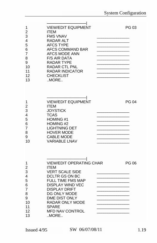
——————————|1 VIEW/EDIT EQUIPMENT PG 032 ITEM3 VNAV _______________4 RADAR ALT _______________5 AFCS TYPE _______________6 AFCS COMMAND BAR _______________7 AFCS MODE ANN _______________8 F/S AIR DATA _______________9 RADAR TYPE _______________10 RADAR CTL PNL _______________11 RADAR INDICATOR _______________12 CHECKLIST _______________13 ..MORE..
——————————|1 VIEW/EDIT EQUIPMENT PG 042 ITEM3 JOYSTICK _______________4 TCAS _______________5 HOMING #1 _______________6 HOMING #2 _______________7 LIGHTNING DET _______________

System Configuration
1.8 Issued 4/95SW 06/07/08/11
——————————|1 VIEW/EDIT OPERATING CHAR PG 062 ITEM3 VERT SCALE SIDE _______________4 DCLTR GS ON BC _______________5 FULLTIME FMS MAP _______________6 DISPLAY WIND VEC _______________7 DISPLAY DRIFT _______________8 DG ONLY MODE _______________9 DME DIST ONLY _______________10 RADAR ONLY MODE _______________11 HOVER MODE _______________12 MFD NAV CONTROL _______________13 ..MORE..
——————————|1 VIEW/EDIT OPERATING PG 072 ITEM3 DISPLAY HDG TAPE _______________4 COMMAND BARS _______________5 ROLL INDICATOR _______________6 DCLTR UNUS ATT _______________7 CAT II AVAILABLE _______________8 PERSPECTIVE LINES _______________9 DH SELECT _______________10 CABLE MODE _______________11 SEL HDG SYNC _______________12 SEL CRS SYNC _______________13 ..MORE..

System Configuration
1.9Issued 4/95 SW 06/07/08/11
——————————|1 VIEW/EDIT OPERATING PG 082 ITEM3 NORTH UP MAP _______________4 VERT PTR TYPE _______________5 DISPLAY FMS MSG _______________6 SEL HDG COLOR _______________7 CMD BAR COLOR _______________8 REV MODE ANN _______________9 RISING RUNWAY _______________10 ADI DEV SRC _______________11 CMD BAR FILTER _______________

System Configuration
1.10 Issued 4/95SW 06/07/08/11
SOFTWARE 07 CONFIGURATION PAGES(includes both 0701 and 0702)
The EHSI, EADI, MFD and Reversion software will display the follow-ing pages. All display information will be identical on the EHSI andMFD, however, the EADI will not display the rack configurations, it willdisplay a comparison of the EHSI and EADI configuration data. Thedescriptions given in this section refer to side 1 (left side) as the pilot’sside and side 2 (right side) as the co-pilot’s side.
——————————| 1 VIEW/EDIT EQUIPMENT PG 012 ITEM3 SG NUMBER _______________4 SINGLE/DUAL _______________5 DU TYPE _______________6 ATTITUDE/HDG #1 _______________7 ATTITUDE/HDG #2 _______________8 RATE OF TURN _______________9 ADF #1 _______________10 ADF #2 _______________11 VOR/ILS #1 _______________12 VOR/ILS #2 _______________13 ..MORE..

System Configuration
1.11Issued 4/95 SW 06/07/08/11
——————————|1 VIEW/EDIT EQUIPMENT PG 022 ITEM3 DME #1 _______________4 DME #2 _______________5 MLS #1 _______________6 MLS #2 _______________7 FMS #1 _______________8 FMS #2 _______________9 RNAV #1 _______________10 RNAV #2 _______________11 TACAN #1 _______________12 TACAN #2 _______________13 ..MORE..
——————————|1 VIEW/EDIT EQUIPMENT PG 032 ITEM3 VNAV _______________4 RADAR ALT _______________5 AFCS TYPE _______________6 AFCS COMMAND BAR _______________7 AFCS MODE ANN _______________8 F/S AIR DATA _______________9 RADAR TYPE _______________10 RADAR CTL PNL _______________11 RADAR INDICATOR _______________12 CHECKLIST _______________13 ..MORE..

System Configuration
1.12 Issued 4/95SW 06/07/08/11
——————————|1 VIEW/EDIT EQUIPMENT PG 042 ITEM3 JOYSTICK _______________4 TCAS _______________5 HOMING #1 _______________6 HOMING #2 _______________7 LIGHTNING DET _______________8 HOVER MODE _______________9 CABLE MODE _______________
——————————|1 VIEW/EDIT OPERATING CHAR PG 062 ITEM3 VERT SCALE SIDE _______________4 DCLTR GS ON BC _______________5 FULL TIME FMS MAP _______________6 DISPLAY WIND VEC _______________7 DISPLAY DRIFT _______________8 DG ONLY MODE _______________9 DME DIST ONLY _______________10 RADAR ONLY MODE _______________11 SPARE _______________12 MFD NAV CONTROL _______________13 ..MORE..

System Configuration
1.13Issued 4/95 SW 06/07/08/11
——————————|1 VIEW/EDIT OPERATING PG 072 ITEM3 DISPLAY HDG TAPE _______________4 COMMAND BARS _______________5 ROLL INDICATOR _______________6 DCLTR UNUS ATT _______________7 CAT II AVAILABLE _______________8 PERSPECTIVE LINES _______________9 DH SELECT _______________10 CTL PNL SYNC _______________11 SEL HDG SYNC _______________12 SEL CRS SYNC _______________13 ..MORE..
1 VIEW/EDIT OPERATING PG 082 ITEM3 NORTH UP MAP _______________4 VERT PTR TYPE _______________5 DISPLAY FMS MSG _______________6 SEL HDG COLOR _______________7 CMD BAR COLOR _______________8 REV MODE ANN _______________9 RISING RUNWAY _______________10 ADI DEV SRC _______________11 CMD BAR FILTER _______________

System Configuration
1.14 Issued 4/95SW 06/07/08/11
SOFTWARE 08 CONFIGURATION PAGES
The EHSI, EADI, MFD and Reversion software will display the follow-ing pages. All display information will be identical on the EHSI andMFD, however, the EADI will not display the rack configurations, it willdisplay a comparison of the EHSI and EADI configuration data. Thedescriptions given in this section refer to side 1 (left side) as the pilot’sside and side 2 (right side) as the co-pilot’s side.
——————————| 1 VIEW/EDIT EQUIPMENT PG 012 ITEM3 SG NUMBER _______________4 SINGLE/DUAL _______________5 DU TYPE _______________6 ATTITUDE/HDG #1 _______________7 ATTITUDE/HDG #2 _______________8 RATE OF TURN _______________9 ADF #1 _______________10 ADF #2 _______________11 VOR/ILS #1 _______________12 VOR/ILS #2 _______________13 ..MORE..
——————————|1 VIEW/EDIT EQUIPMENT PG 022 ITEM3 DME #1 _______________4 DME #2 _______________5 MLS #1 _______________6 MLS #2 _______________7 FMS #1 _______________8 FMS #2 _______________9 RNAV #1 _______________10 RNAV #2 _______________11 TACAN #1 _______________12 TACAN #2 _______________13 ..MORE..

System Configuration
1.15Issued 4/95 SW 06/07/08/11
——————————|1 VIEW/EDIT EQUIPMENT PG 032 ITEM3 VNAV _______________4 RADAR ALT _______________5 AFCS TYPE _______________6 AFCS COMMAND BAR _______________7 AFCS MODE ANN _______________8 F/S AIR DATA _______________9 RADAR TYPE _______________10 RADAR CTL PNL _______________11 RADAR INDICATOR _______________12 CHECKLIST _______________13 ..MORE..
——————————|1 VIEW/EDIT EQUIPMENT PG 042 ITEM3 JOYSTICK _______________4 TCAS _______________5 HOMING #1 _______________6 HOMING #2 _______________7 LIGHTNING DET _______________8 HOVER MODE _______________9 CABLE MODE _______________

System Configuration
1.16 Issued 4/95SW 06/07/08/11
——————————|1 VIEW/EDIT OPERATING CHAR PG 062 ITEM3 VERT SCALE SIDE _______________4 DCLTR GS ON BC _______________5 FULL TIME FMS MAP _______________6 DISPLAY WIND VEC _______________7 DISPLAY DRIFT _______________8 DG ONLY MODE _______________9 DME DIST ONLY _______________10 RADAR ONLY MODE _______________11 SPARE _______________12 MFD NAV CONTROL _______________13 ..MORE..
——————————|1 VIEW/EDIT OPERATING PG 072 ITEM3 DISPLAY HDG TAPE _______________4 COMMAND BARS _______________5 ROLL INDICATOR _______________6 DCLTR UNUS ATT _______________7 CAT II AVAILABLE _______________8 PERSPECTIVE LINES _______________9 DH SELECT _______________10 CTL PNL SYNC _______________11 SEL HDG SYNC _______________12 SEL CRS SYNC _______________13 ..MORE..
System Configuration
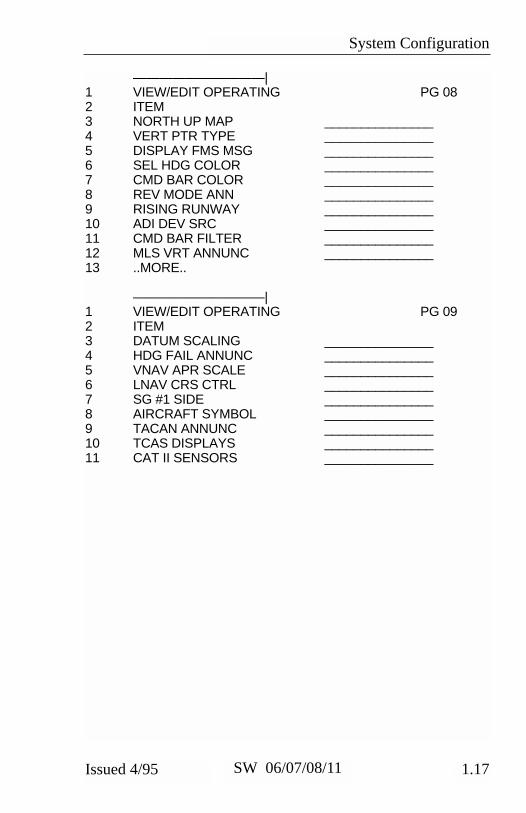
1.17Issued 4/95 SW 06/07/08/11
——————————|1 VIEW/EDIT OPERATING PG 082 ITEM3 NORTH UP MAP _______________4 VERT PTR TYPE _______________5 DISPLAY FMS MSG _______________6 SEL HDG COLOR _______________7 CMD BAR COLOR _______________8 REV MODE ANN _______________9 RISING RUNWAY _______________10 ADI DEV SRC _______________11 CMD BAR FILTER _______________12 MLS VRT ANNUNC _______________13 ..MORE..
——————————|1 VIEW/EDIT OPERATING PG 092 ITEM3 DATUM SCALING _______________4 HDG FAIL ANNUNC _______________5 VNAV APR SCALE _______________6 LNAV CRS CTRL _______________7 SG #1 SIDE _______________8 AIRCRAFT SYMBOL _______________9 TACAN ANNUNC _______________10 TCAS DISPLAYS _______________11 CAT II SENSORS _______________

System Configuration
1.18 Issued 4/95SW 06/07/08/11
SOFTWARE 11 CONFIGURATION PAGES
The EHSI, EADI, MFD and Reversion software will display the follow-ing pages. All display information will be identical on the EHSI andMFD, however, the EADI will not display the rack configurations, it willdisplay a comparison of the EHSI and EADI configuration data. Thedescriptions given in this section refer to side 1 as the pilot’s side andside 2 as the co-pilot’s side.
——————————| 1 VIEW/EDIT EQUIPMENT PG 012 ITEM3 SG NUMBER _______________4 SINGLE/DUAL _______________5 DU TYPE _______________6 ATTITUDE/HDG #1 _______________7 ATTITUDE/HDG #2 _______________8 RATE OF TURN _______________9 ADF #1 _______________10 ADF #2 _______________11 VOR/ILS #1 _______________12 VOR/ILS #2 _______________13 ..MORE..
——————————|1 VIEW/EDIT EQUIPMENT PG 022 ITEM3 DME #1 _______________4 DME #2 _______________5 MLS #1 _______________6 MLS #2 _______________7 FMS #1 _______________8 FMS #2 _______________9 RNAV #1 _______________10 RNAV #2 _______________11 TACAN #1 _______________12 TACAN #2 _______________13 ..MORE..
System Configuration
1.19Issued 4/95 SW 06/07/08/11
——————————|1 VIEW/EDIT EQUIPMENT PG 032 ITEM3 FMS VNAV _______________4 RADAR ALT _______________5 AFCS TYPE _______________6 AFCS COMMAND BAR _______________7 AFCS MODE ANN _______________8 F/S AIR DATA _______________9 RADAR TYPE _______________10 RADAR CTL PNL _______________11 RADAR INDICATOR _______________12 CHECKLIST _______________13 ..MORE..
——————————|1 VIEW/EDIT EQUIPMENT PG 042 ITEM3 JOYSTICK _______________4 TCAS _______________5 HOMING #1 _______________6 HOMING #2 _______________7 LIGHTNING DET _______________8 HOVER MODE _______________9 CABLE MODE _______________10 VARIABLE LNAV _______________
——————————|1 VIEW/EDIT OPERATING CHAR PG 062 ITEM3 VERT SCALE SIDE _______________4 DCLTR GS ON BC _______________5 FULL TIME FMS MAP _______________6 DISPLAY WIND VEC _______________7 DISPLAY DRIFT _______________8 DG ONLY MODE _______________9 DME DIST ONLY _______________10 RADAR ONLY MODE _______________11 SPARE _______________12 MFD NAV CONTROL _______________13 ..MORE..
System Configuration
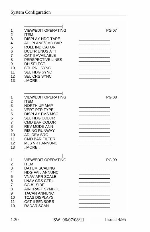
1.20 Issued 4/95SW 06/07/08/11
——————————|1 VIEW/EDIT OPERATING PG 072 ITEM3 DISPLAY HDG TAPE _______________4 ADI PLANE/CMD BAR _______________5 ROLL INDICATOR _______________6 DCLTR UNUS ATT _______________7 CAT II AVAILABLE _______________8 PERSPECTIVE LINES _______________9 DH SELECT _______________10 CTL PNL SYNC _______________11 SEL HDG SYNC _______________12 SEL CRS SYNC _______________13 ..MORE..
——————————|1 VIEW/EDIT OPERATING PG 082 ITEM3 NORTH UP MAP _______________4 VERT PTR TYPE _______________5 DISPLAY FMS MSG _______________6 SEL HDG COLOR _______________7 CMD BAR COLOR _______________8 REV MODE ANN _______________9 RISING RUNWAY _______________10 ADI DEV SRC _______________11 CMD BAR FILTER _______________12 MLS VRT ANNUNC _______________13 ..MORE..
——————————|1 VIEW/EDIT OPERATING PG 092 ITEM3 DATUM SCALING _______________4 HDG FAIL ANNUNC _______________5 VNAV APR SCALE _______________6 LNAV CRS CTRL _______________7 SG #1 SIDE _______________8 AIRCRAFT SYMBOL _______________9 TACAN ANNUNC _______________10 TCAS DISPLAYS _______________11 CAT II SENSORS _______________10 RADAR SCAN _______________

System Configuration
1.21Issued 4/95 SW 06/07/08/11
——————————|1 VIEW/EDIT OPERATING PG 102 ITEM3 RADAR SDI _______________4 PITCH SYNC DISC _______________

System Configuration
1.22 Issued 4/95SW 06/07/08/11
* This page intentionally left blank.
EHSI Operation
2.1.1Issued 4/95 SW 06/07/08/11
EHSI OPERATION
DETAILED OPERATING CONTROLS
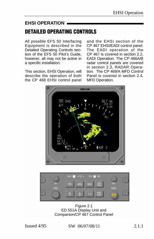
All possible EFS 50 InterfacingEquipment is described in theDetailed Operating Controls sec-tion of the EFS 50 Pilot’s Guide,however, all may not be active ina specific installation.
This section, EHSI Operation, willdescribe the operation of boththe CP 468 EHSI control panel
and the EHSI section of theCP 467 EHSI/EADI control panel.The EADI operation of theCP 467 is covered in section 2.2,EADI Operation. The CP 466A/Bradar control panels are coveredin section 2.3, RADAR Opera-tion. The CP 469/A MFD ControlPanel is covered in section 2.4,MFD Operation.
Figure 2.1ED 551A Display Unit and
Companion/CP 467 Control Panel
1
VOR
1
CRS 340 36.7 NM
N
33 3
243 KT
90°
40
36.7 NMVOR 1
ADF 2
ARLWXA
ANT FLTA 2.2
230:09
HSI ARC NAV RNG
1-2
HDGCRS
RNG
RALT TST SYS
BRT
REF
DH

EHSI Operation
2.1.2 Issued 4/95SW 06/07/08/11
Figure 2.2CP 467 Control Panel
alone EHSI/EADI Mode Con-troller & companion ED 551/ADisplay unit and figure 2.2 showsthe CP 467 Mode ControllerOperation.
For clarification on a particulardisplay or operational feature,refer to section IV. EHSI DIS-PLAYS or section V. OPERAT-ING INSTRUCTIONS. Figure2.1 shows the CP 467 stand-
HSI ARC NAV RNG
1-2
HDGCRS
RNG
RALT TST SYS
BRT
REF
DH
TEST/REF TEST*GROUND SPEED*TIME-TO-STATION NAV MAP FORMAT
360 MODE SELECTHSI COMPASS ROSENAV MAPNAV MAP WITH WXDG
NAV SOURCE SELECTVOR, LOC,TCN or RNVTCNFMS, LOR, OMG or GPSNAVMLSADFHOM
SYSTEM 1-2 SELECT
RANGE SELECTNAV MAPWX
#2 BEARING POINTER SELECTDECLUTTERVOR, TCN OR RNVTCNFMS, LOR, OMG, or GPSNAVMLSADFDME DISTANCE ONLY
SECTORED MODE SELECTARC COMPASS ROSEARC NAV MAPARC NAV MAP WITH WXARC COMPASS ROSE WITH WX
#1 BEARING POINTER SELECTDECLUTTERVOR, TCN OR RNVTCNFMS, LOR, OMG, or GPSNAVMLSADFDME DISTANCE ONLY
*NO SELECTION AFTER SW 08
PULL SETRADIO ALTIMETER
PUSH TESTRADIO ALTIMETER

EHSI Operation
2.1.3Issued 4/95 SW 06/07/08/11
EHSI CONTROLS (CP 467)HSI 360-DEGREE MODESELECTION
The EFS 50 has four possible360-degree display formats:standard HSI compass rose,NAV map, NAV map with weath-er, and DG mode. Each press ofthe HSI button sequentiallyselects the next display format.A press of the HSI button while inthe ARC mode will change thedisplay to the standard HSI com-pass rose.
The display selection list mayinclude the following:
DG ONLY and WEATHER areoptions selected at the time ofinstallation and are included inthe system certification.
If a compatible weather radar isnot installed, the weather optionwill not be in the sequence.
ARC SECTORED MODESELECTION
The ARC mode provides the pilota large scale view of the CDI bypresenting an approximate 85-degree sector display of the com-pass.
The EFS 50 has five possibleARC sectored display formats:standard HSI compass rose,NAV CDI map, NAV CDI mapwith weather and standard HSIcompass rose with weather. Asoftware configuration option,selectable at the time of installa-tion and certification, allows aweather only mode to be select-ed on the MFD. A press of theARC button will sequentiallyselect the possible display for-mats.
A press of the ARC button whilein the 360-degree mode willresult in an ARC presentation ofthe same format. For example, ifthe 360 NAV MAP WITHWEATHER mode is being dis-
HSI
ARC
HSI
HSI COMPASS ROSE
HSI NAV MAP
HSI NAV MAPWITH WEATHER(OPTIONAL)
DG MODE(OPTIONAL)
PLAN VIEW(OPTIONAL ON MFD)

EHSI Operation
2.1.4 Issued 4/95SW 06/07/08/11
played and the ARC button ispressed, the resulting display for-mat will be ARC NAV MAP WITHWEATHER.
The ARC display selection listmay include the following:
WEATHER is an option selectedat the time of installation and isincluded in the system certifica-tion. If a compatible weatherradar is not installed, the weatheroption will not be in thesequence.
An additional ARC format optionis offered, selectable at the timeof installation and certification,which provides an unclutteredweather radar presentation onthe MFD. The MFD ARC weath-er only format provides a typicalweather radar presentation, nonavigation data is presentedwhen this mode is selected.
Refer to radar controls in thissection for details on weatherradar operation.
NAV NAVIGATION SENSORSELECT
During installation, the EFS 50symbol generator was pro-grammed with the type andquantity of each piece of interfac-ing equipment. Not all theequipment interfaced to theEFS 50 is usable for primary nav-igation. The EFS 50 creates andmaintains in permanent memorya list of the interfacing navigationsensors.
The NAV push button is used toselect which NAV sensor pro-vides primary navigation data. A
ARC
ARC COMPASS ROSE
ARC NAV MAP
ARC NAV MAP WITH WEATHER (OPTIONAL)
ARC COMPASS ROSE WITH WEATHER (OPTIONAL)
ARC WEATHER ONLY (OPTIONAL ON MFD)
NAV

EHSI Operation
2.1.5Issued 4/95 SW 06/07/08/11
press of the NAV sensor selectbutton sequentially selects thenext available sensor from the listof those installed. Primary Navi-gation Data is defined as the dis-tance in the upper right corner,selected course, course pointerand deviation.
The Primary Navigation Sensoris annunciated at the side of the
display unit opposite the verticalscale. Only those sensors inter-faced to the EFS 50 in a specificinstallation will be selectable foruse and display.
The following is an all-inclusivelist, in order, of primary naviga-tion sensors that may be inter-face with the EFS 50:
NOTES: If a number 2 NAV sensor has been selected for displayon the number 1 EHSI by pressing the 1-2 button and the number
MLS
LNAV, (FMS, LOR OMG or GPS)
TCN (Control head)
ADF
HOM
TCN (Control head)
VOR (VOR, LOC, TCN or RNV) VOR (VOR, LOC, TCN or RNV)
LNAV, (FMS, LOR, OMG, or GPS)
MLS
ADF
HOM
ON-SIDE EFS CROSS-SIDE EFS
1-2
1-2
1-2
1-2
1-2
NAV
NAV
NAV
NAV
NAV
NAV
NAV
1-2
NAV
NAV
NAV
NAV
NAV

EHSI Operation
2.1.6 Issued 4/95SW 06/07/08/11
1 EHSI NAV push button ispressed, the next availablenumber 1 NAV sensor will beselected.
ADF D-Bar presentation maynot be available if the ADFdoes not provide a suitableflag output.
Software 08 treats unlike LNAVsources (i.e. FMS, LOR, OMG, orGPS) as single sensors. Whentwo unlike LNAV sources areconfigured, the EFS will displayboth the on-side LNAV and theoff-side LNAV without a systemnumber and the NAV button isused to select between them.
1-2 NAVIGATION SYSTEMSELECT
The 1-2 button is used to cyclebetween primary navigation sen-sor system #1 and #2 for display.The primary NAV system select-ed is annunciated as sensor 1 orsensor 2 on the EHSI. Example,if VOR 1 is being displayed andthe 1-2 button is pressed, VOR 2will become the displayed sen-sor. If only one sensor isinstalled, the display will not cycleand the sensor annunciation willnot show a system number. Forexample ADF would be displayed(not ADF 1) in installations con-taining a single ADF.
Note: The cross-side sensor forVOR could be TCN, for LNAVsit could be a combination ofFMS, OMG , LOR, or GPS.After software 08, the 1-2 but-ton no longer selects betweenunlike LNAV sources.
When a RMI or NAV sensorselect button is pressed and itis not active in the system, ayellow “FUNCTION NOTIMPLEMENTED” will be dis-played in the center of thescreen.
BEARING POINTERSELECT
The bearing pointer select but-tons work in a similar manner asthe NAV sensor select button. Apress of the bearing pointer but-ton sequentially selects the nextavailable sensor for display. Thebearing pointer sensor list con-tains only those sensors whichhave bearing information capabil-ities. If the selected sensor hasdistance information paired withit, that distance will also be dis-played below the sensor annun-ciation. An optional push buttonsequence allows independentselection and display of therespective DME distance withoutthe presence of the bearingpointer.
1-2

EHSI Operation
2.1.7Issued 4/95 SW 06/07/08/11
The following is an all-inclusive list, in order, of the bearing pointersensors that may be interfaced with the EFS 50:
Only those sensors interfaced tothe EFS 50 will be included in thesequence.
Software 07 added an optionselectable at the time of installa-tion and certification thatremoves the ability to display aMLS bearing pointer.
For a single ADF installation,the ADF bearing pointer maybe displayed on either the sin-gle or double bar pointer. Theannunciation associated witheither bearing pointer will beADF, not ADF 1 or ADF 2.
Note: Any single bearingpointer sensor may be dis-played on either pointer. Thisincludes unlike LNAV sourcesafter software 08.
RANGE SELECTION
A press of the RANGE DOWNbutton selects the next lowerrange to be displayed while in theNAV MAP or WEATHER modesof operation. Once the lowestselectable range is reached, theRANGE UP button must be usedfor a range change.
The operation of the RANGE UPbutton is similar to the RANGEDOWN except it selects the nexthigher range to be displayedwhile in the NAV MAP orWEATHER modes of operation.
Note: To display weather infor-mation on the copilot’s EHSI itselected range must matchone of those ranges displayedon the MFD or pilot’s EHSI.
RNGRNG
DECLUTTER, (NO #1 OR #2 BEARING POINTER INFORMATION IS DISPLAYED)
VOR, (VOR OR TCN)
TCN, (ONLY AVAILABLE WHEN THE TACAN HAS AN INDEPENDENT CONTROL HEAD)
LNAV , (FMS, LOR, OMG, OR GPS)
MLS
ADF
DME DISTANCE ONLY, (OPTIONAL)
OR

EHSI Operation
2.1.8 Issued 4/95SW 06/07/08/11
When the map range on theMFD or pilot’s EHSI no longermatches the range selected onthe copilot’s EHSI the copilotwill display stale weather infor-mation for 30 seconds. A “WXFLT” warning will then displayon the RADAR fault warningline alerting the pilot of rangemismatch.
TST/REF
The TST/REF button performsthree functions: SELF TEST dis-play, Ground speed or Time-to-Station selection and LNAV MAPformatting.
◗ TST -
To display the EHSI systemSELF TEST, press and hold theTST/REF button for three sec-onds. Upon entering Self Test, atest pattern will be displayed. Inthe center of the test pattern,either a SELF TEST PASS orSELF TEST FAIL will be annun-ciated. With 06 software, theSELF TEST display will remainuntil the TST/REF button ispressed again. Beginning with07 software, the EFIS will cancelthe test mode and return both theEADI and EHSI to normal opera-tion after 5 seconds.
Note: If the SELF TEST FAILmessage is annunciated, thesystem should be serviced.
◗ REF GROUND SPEED orTIME-TO-STATION selection
With software 06 and 07, theTST/REF button allows alternateselection of Ground speed orTime-to-station (in minutes) ascalculated by the selected prima-ry NAV system. When Groundspeed or Time-to-station informa-tion is available it will be dis-played below the distance infor-mation in the upper right cornerof the display. If the informationis not provided, the associatedannunciator will be removed.The alternate selection of Groundspeed and Time-to-station willnot be allowed in the MAP modewith an LNAV selected as the pri-mary navigation source.
After software 08, both groundspeed and Time-to-station aredisplayed simultaneously. Time-to-station is displayed immediate-ly below the Ground speed usingthe format of hours and minutesseperated by a colon (H:MM).
Note: The Time-to-station fieldused with software 08 can alsobe used for an abnormal DMEannunciation which has priority.
The EFS 50 will calculate groundspeed and Time-to-station ininstallations which use an ARINC568 type DME. If a conventionalDME indicator is also used, dif-ferences in ground speed andTime-to-station display may benotices.
SYS REF

EHSI Operation
2.1.9Issued 4/95 SW 06/07/08/11
Note: Time-to-station is replacedwith Time-to-waypoint when theselected primary nav is an LNAVproviding this information.
◗REF MAP FORMAT
When the selected EFS 50 dis-play is LNAV MAP, the TST/REFbutton allows selection of thedesired NAV MAP format. Todetermine the present MAP for-mat momentarily press theTST/REF button. The momen-tary button press will activate thepresent MAP format annuncia-tion. If the displayed format isdesired, no additional action isrequired; the format message willbe removed within 5 seconds. Ifa different format is desired,
sequence through the list bymomentarily pressing theTST/REF button until the desiredformat is displayed. Approxi-mately 5 seconds after the lastbutton press, the map formatannunciation will be removed.
With software 06 and 07, theNAV map format will remain aspreviously selected until changedusing the TST/REF button, how-ever beginning with 08 softwarethe NAV map format is re-set toFPL ID each time a MAP displayis activated.
The following is an all-inclusivelist, in order, of the possible NAVMAP formats:
Note: Depending upon the Flight Management System installed,the above format options may not be fully supported. Systemssuch as the BENDIX/KING KNS 660 and KLN 88, that support theGAMA 429 LNAV data bus will provide the above format options.
FPL ID
AIRPORT
NAVAIDS
TEST
REF
(FLIGHT PLAN WITHFULL ICAO IDENTIFIERS)
(TO WAYPOINT AND NEARESTAIRPORTS WITH ICAO IDENTIFIERS)
(TO WAYPOINT AND NEAREST NAVAIDSWITH ICAO IDENTIFIERS)
EHSI Operation
2.1.10 Issued 4/95SW 06/07/08/11
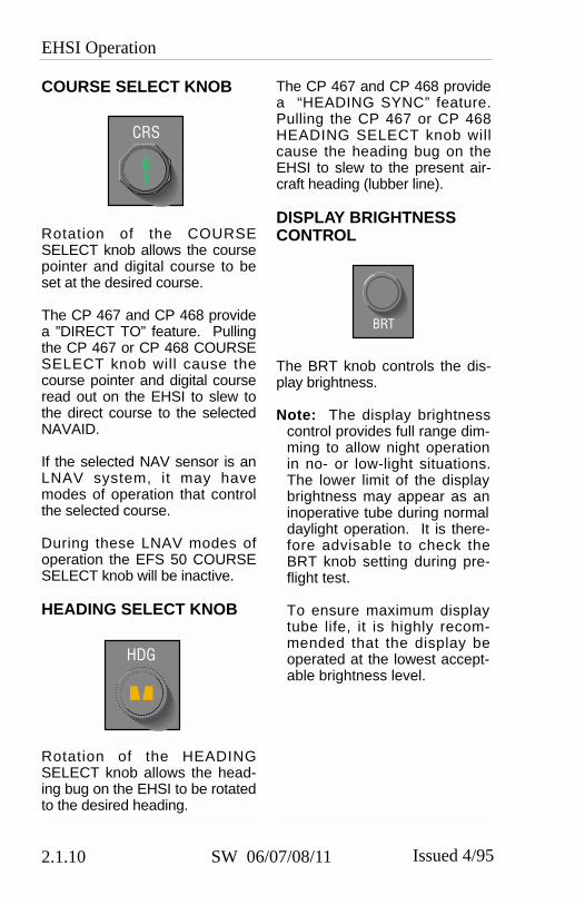
COURSE SELECT KNOB
Rotation of the COURSESELECT knob allows the coursepointer and digital course to beset at the desired course.
The CP 467 and CP 468 providea ”DIRECT TO” feature. Pullingthe CP 467 or CP 468 COURSESELECT knob will cause thecourse pointer and digital courseread out on the EHSI to slew tothe direct course to the selectedNAVAID.
If the selected NAV sensor is anLNAV system, it may havemodes of operation that controlthe selected course.
During these LNAV modes ofoperation the EFS 50 COURSESELECT knob will be inactive.
HEADING SELECT KNOB
Rotation of the HEADINGSELECT knob allows the head-ing bug on the EHSI to be rotatedto the desired heading.
The CP 467 and CP 468 providea “HEADING SYNC” feature.Pulling the CP 467 or CP 468HEADING SELECT knob willcause the heading bug on theEHSI to slew to the present air-craft heading (lubber line).
DISPLAY BRIGHTNESSCONTROL
The BRT knob controls the dis-play brightness.
Note: The display brightnesscontrol provides full range dim-ming to allow night operationin no- or low-light situations.The lower limit of the displaybrightness may appear as aninoperative tube during normaldaylight operation. It is there-fore advisable to check theBRT knob setting during pre-flight test.
To ensure maximum displaytube life, it is highly recom-mended that the display beoperated at the lowest accept-able brightness level.
CRS
HDG
BRT
EADI Operation
2.2.1Issued 4/95 SW 06/07/08/11
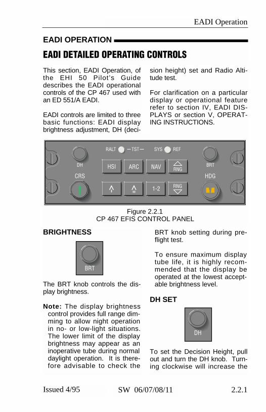
This section, EADI Operation, ofthe EHI 50 Pilot’s Guidedescribes the EADI operationalcontrols of the CP 467 used withan ED 551/A EADI.
EADI controls are limited to threebasic functions: EADI displaybrightness adjustment, DH (deci-
sion height) set and Radio Alti-tude test.
For clarification on a particulardisplay or operational featurerefer to section IV, EADI DIS-PLAYS or section V, OPERAT-ING INSTRUCTIONS.
EADI OPERATION
EADI DETAILED OPERATING CONTROLS
Figure 2.2.1CP 467 EFIS CONTROL PANEL
BRIGHTNESS
The BRT knob controls the dis-play brightness.
Note: The display brightnesscontrol provides full range dim-ming to allow night operationin no- or low-light situations.The lower limit of the displaybrightness may appear as aninoperative tube during normaldaylight operation. It is there-fore advisable to check the
BRT knob setting during pre-flight test.
To ensure maximum displaytube life, it is highly recom-mended that the display beoperated at the lowest accept-able brightness level.
DH SET
To set the Decision Height, pullout and turn the DH knob. Turn-ing clockwise will increase the
HSI ARC NAV RNG
1-2
HDGCRS
RNG
RALT TST SYS
BRT
REF
DH
BRT
DH

EADI Operation
2.2.2 Issued 4/95SW 06/07/08/11
Decision Height selected, turningcounter clockwise will decreasethe Decision Height. The DH setknob is variable rate, the fasterthe knob is turned, the greaterthe change in a given amount ofrotation. The Decision Heightrange is from “OFF” to 2,500 feetand will be displayed in one footincrements up to 500 feet andthen in 10 foot increments to2,500 feet.
Once the desired DH is selected,push in the DH set knob to lockthe selected DH altitude. If DH isset to OFF, the “DH” annuncia-tion will not be displayed.
RALT TST
Pressing the RALT TST (RadioAltimeter Test) push button pro-vides a discrete output to theRadio Altimeter initiating its selftest function.
RALT TST

Radar Operation
2.3.1Issued 4/95 SW 06/07/08/11
WARNING!This Instrument generates microwave radiation
DO NOT OPERATE UNTIL YOU HAVE READ AND CAREFULLY FOLLOWED ALL SAFETY
PRECAUTIONS AND INSTRUCTIONS INTHE OPERATING AND SERVICE MANUALS
IMPROPER USE OR EXPOSURE MAY CAUSESERIOUS BODILY INJURY
Radiation
Caution:1. Maintain prescribed safedistance when standing in frontof a radiation antenna.*
*Reference FAA AdvisoryCircular #20-68B
2. Never expose eyes or anypart of the body to anunterminated waveguide.

Radar Operation
2.3.2 Issued 4/95SW 06/07/08/11
Maximum Permissible Exposure Level (MPEL)
In order to avoid the envelope inwhich the radiation level exceedsthe U.S. Government standard of10 mW per square centimeter, allpersonnel should remain beyondthe distance indicated in the illus-tration below. The distance tothe MPEL boundary is calculatedupon the basis of the largestantenna available with the RDS
81/82/82 VP/84/84 VP/86 and 86VP system, rated output power ofthe transmitter and in the nonrotating boresight position of theantenna.
With a scanning beam the powerdensity at the MPEL boundary issignificantly reduced.
3 FEET
RADOME
CL OF AIRCRAFT
MPEL BOUNDARY
180˚

Radar Operation
2.3.3Issued 4/95 SW 06/07/08/11
The following section providesgeneral operating information onEFS 50 radar control panels,CP 466A & CP 466B. Figure2.3.1 shows the CP 466A usedwith an RDS 81, RDS 82 orRDS 82VP, RDS 84 or
RDS 84VP. Figure 2.3.2 showsthe CP 466B used with anRDS 86 or RDS 86VP. Fordetailed information on the spe-cific weather radar functions,refer to the appropriate radarpilot’s guide.
RADAR OPERATION
RADAR CONTROLS, (CP 466A & CP 466B)
Figure 2.3.1CP 466A
Figure 2.3.2 CP 466B
Note: The CP 466A and B shown include the push buttons requiredfor the Vertical Profile radars. For non-VP installations using theCP 466A or B the VP and two track buttons will not be present.
ONTST
STBY
OFF
GAIN
Wx WxA GNDMAP
UPTILT O
DN
VP TK
PULL STAB OFF
TRKTRK
ONTST
STBY
OFF
GAIN
Wx WxA GNDMAP
UPTILT O
DNPULL AUTOPULL ARL
VP TK TKTRKTRK

Radar Operation
2.3.4 Issued 4/95SW 06/07/08/11
OFF-STBY-TST-ON
The rotary OFF-STBY-TST-ONknob selects the desired operat-ing condition for the radar.
◗OFF
Disables the ART (Antenna,Receiver and Transmitter) powersupply. “OFF” is displayed belowthe NAV source annunciator onthe radar mode line.
◗ STBY
After 30 seconds in this mode,the system is in a state of readi-ness. No radar transmissionoccurs, and the antenna isparked in the down position.“STBY” is displayed below theNAV source annunciator on theradar mode line, if a weathermode is selected.
◗ TST
Causes the test pattern to be dis-played on the indicator, if aweather mode is selected.“TEST” is displayed below theNAV source annunciator on theradar mode line.
◗ ON
Selects the condition of normaloperation, allowing for weatherdetection or other modes of oper-
ation. Depending on the select-ed mode of operation, WX,WXAor MAP is displayed below theNAV source annunciator on theradar mode line.
Note: If “ON” is selected on theCP 466 radar control panel,the radar Antenna, Receiverand Transmitter (ART) is oper-ational. However, if a weatherradar mode is not selected fordisplay on one of the indica-tors the ART is placed instandby by the EFIS.
WX
Selects the weather mode (WX)when pressed. “WX” will be dis-played below the NAV sourceannunciator on the radar modeline, if a weather mode is selected.
WXA
Selects the weather-alert modewhen pressed. The magentaarea of a storm will flash betweenmagenta and black. “WXA” willbe displayed below the NAVsource annunciator on the radarmode line, if a weather mode isselected.
GND MAP
Places the radar in ground map-ping mode of operation; disablesweather-alert feature and acti-vates gain control. “MAP” will bedisplayed below the NAV source
ONTST
STBY
OFF
Wx
WxA
GNDMAP

Radar Operation
2.3.5Issued 4/95 SW 06/07/08/11
annunciator on the radar modeline. (Magenta is not active in theGND MAP mode.)
LIGHTNING
❏ (Optional) Enables the Light-ning display when pressed if aweather mode is selected for dis-play.
VP
❏ (Optional) Once the desiredazimuth is selected with the TRKbutton, press the VP button toenter the Vertical Profile mode ofoperation. The Vertical ProfileScreen will appear. The weathermode of operation (WX, WXA orGND MAP) displayed in thelower left corner of the displaywill be the same as existed justprior to selecting VP. To select adifferent weather mode once inVertical Profile, simply select thedesired mode (WX, WXA or GNDMAP) by pressing the appropri-ate button.
Note: A brief period of time willnormally elapse before the dis-play will “paint” the VerticalProfile “picture”. This timedelay is due to the fact that theradar continues its normalazimuth scan after the VP but-ton is pressed.
The operation of scanning theantenna vertically (+/- 20 or +/-30 degrees depending on the
Radar) is referred to as takinga vertical “slice”.
Once Vertical Profile is selected,the desired profile-azimuth anglemay be changed in two degreeincrements by pressing and hold-ing the appropriate TRK button.One of two things will happenwhen a TRK button is pressed:(1) If the radar’s antenna isalready profiling, the antenna willmove in the two-degree incre-ments, “slicing” in the directiondetermined by the TRK button; or(2) A “WAIT” annunciation will bedisplayed indicating that theradar’s antenna will perform thedesired “slicing” function as soonas the antenna returns to the lastselected profiling-azimuth angle.
Note: Depending on the soft-ware version of the RDS VPradar and the system installa-tion, the antenna may alsoscan horizontally while in theVP mode. If the antenna isnot sweeping vertically whenthe TRK button is pressed, a“WAIT” annunciation will bedisplayed until the antennareturns to the last vertical“slice” azimuth.
To terminate the Vertical Profilemode and return to the normalmode (horizontal scan), press theVP button. The radar system willretain its existing weather modeand return to horizontal scanning.A track line will be present on thescreen for 15 seconds to indicatethe location of the last profiling-azimuth angle.
VP

Radar Operation
2.3.6 Issued 4/95SW 06/07/08/11
Beginning with EFS software ver-sion 11, a Split Screen mode isadded to the VP button selectionsequence immediately followingthe Vertical Profile mode. Durngthis Split Screen mode the EFSwill toggle the antenna betweenvertical and horizontal scansevery 6 seconds, allowing both tobe displayed simultaneously onthe MFD. See Figure 4.4.4.
Note: This Split Screen mode isan operational enhancementadded to EFS 11 software thatdoes not require any modificationto the existing RDS82VP/84VP/86VP weather sys-tems. Since this feature was notpart of the original design ofthese radars, the transitionbetween horizontal and verticalscans is not synchronized to theantenna scan and will thereforeoccur at random scan positions.
Horizontal (azimuth) and vertical(tilt) track lines are displayed onthe MFD full time during the splitscreen mode to indicate theantenna scan position in eachplane.
TRK
❏ (Optional) If the weather onlymode is selected on the MFD,pressing the TRK button acti-vates and slews a yellow dashedazimuth line. It also activates adigital display showing the num-ber of degrees the azimuth line islocated left or right from the noseof the aircraft. In any other mapweather presentation, only theyellow dashed line will be dis-played.
For VP operations, the TRK but-ton performs two functions. 1.)Prior to engaging VP, the appro-priate button (left or right) is usedto place the track line at thedesired azimuth angle to be verti-cally scanned (sliced). When VPis engaged, the slice will be takenat the last position of the trackline, whether it is visible or not. Ifthe track line has not beenselected after power has beenapplied to system and VP isengaged, the slice will be takenat 0 degrees (directly in front ofthe aircraft). 2.) When in VPmode, pressing the TRK willchange the selected azimuthtwo-degrees left or right, depend-ing on which button is pressed.Continuously holding the TRKbutton will result in the system“slicing” in two-degree incre-ments.
TRKTRK

Radar Operation
2.3.7Issued 4/95 SW 06/07/08/11
GAIN
Manual gain control becomesactive when GND MAP is select-ed. In all other modes, gain isinternally set.
PULL ARL
Only present when an RDS 86 orRDS 86VP is installed. Automat-ic Range Limit displays a bluearea behind weather systemswhere weather detection is nolonger possible because of atten-uation.
TILT
Permits manual adjustment ofantenna tilt 15 degrees up ordown to enable the pilot to ana-lyze the weather presentation.The tilt angle is displayed belowthe NAV source annunciator onthe radar tilt annunciator line.
UP
TILT
DN
GAIN
PULL ARL
If a CP 466A is installed, pull theTilt selector knob, PULL STABOFF, for “STAB OFF” operations.“STAB OFF” will appear on theRadar Fault/Warning line dis-played below the NAV sourceannunciator just under the Anten-na Tilt annunciation line.
If a CP 466B is installed, pull theTilt selector knob, PULL AUTO,for Auto Tilt. If selected, an “A”will follow the tilt direction indica-tion arrow preceding the internal-ly calculated Auto tilt angle sup-plied by the ART.

Radar Operation
2.3.8 Issued 4/95SW 06/07/08/11
* This page intentionally left blank.

MFD Operation
2.4.1Issued 4/95 SW 06/07/08/11
The EFS 50 Multi Function Dis-play Control Panel provides fordisplay of a more meaningfulvariety of data than was previ-ously accessible on EFIS MFDdisplays. In fact, the EFS 50MFD may be used as a secondEHSI by the pilot or copilot, pro-viding them the ability to crosscheck their primary EHSI, pre-view or set up for a potential nav-igation scenario, and still functionas a primary weather radar orLRN map display.
The CP 469 or CP 469A, MFDcontrol panel, provides control ofthe selection of Nav sourceselection, display format andcourse selection. The CP 469Aprovides the additional capabilityof checklist and TCAS traffic dis-plays when used with EFS sys-tem software 08. Weather radarcontrol functions and modeselection are performed by theCP 466, an independent weatherradar control panel.
MFD OPERATION
MULTI FUNCTION DISPLAY CONTROL PANEL
Figure 2.4.1CP 469
Figure 2.4.2CP 469A WITH CHECKLIST & JOYSTICK
HSI ARC NAV RNG
1-2
CRS
RNG
CRS SEL TST
BRT
REF
TST REFCRS SEL
ENTARCHSI
1-2
NAV
CRS
BRT
TCASONLY
CHKLIST

MFD Operation
2.4.2 Issued 4/95SW 06/07/08/11
Those push buttons which havecommon operation between theMFD and EHSI control panels,CP 467 and CP 468, will functionas defined in the section 2.1,EHSI Operation unless otherwisenoted in this section. Fordetailed operational informationon those buttons please refersection 2.1.
TCAS ONLYBUTTON
This button is not functional inSoftware 06 or 07. The message“FUNCTION NOT IMPLEMENT-ED” will be displayed on the MFDif this button is pressed withthese software versions.
With software 08, this button willalternately select between “TCASONLY” and the previously select-ed display on the MFD, if TCASis installed.
HSI BUTTON
Will function identical to, but inde-pendent of, the one on the CP467. The MFD HSI button willallow the additional selection ofan optional plan view on theMFD.
Refer to section 2.1 EHSI OPER-ATION for detailed information.
ARC BUTTON
Will function similar to, but inde-
pendent of, the one on the CP467. The MFD ARC button willallow the selection of an optionalradar only MFD display. This dis-play will not contain navigation ormap data. The ARC button willnot function while Plan-View isdisplayed. The ARC button willnot function while Plan-View isdisplayed.
ENT BUTTON
◗ LNAV MAP
The cursor position informationcan be transferred to the LNAVthat is selected as the primarynavigation sensor, by pressingthe ENTER button while the cur-sor and its coordinates are dis-played. The coordinates of thecursor will remain displayed for atleast 10 seconds and will disap-pear from the display within 15seconds after the ENTER buttonis pressed.
◗ PLAN-VIEW MAP(available with software 07)
When Plan-View is selected,pressing the enter button willplace the symbolic aircraft, pre-sent position, at the center (+) ofthe display.
◗ CHECKLIST(available with software 08)
In the Checklist mode the enterbutton will generally function tocheck items in the list. Thechecklist was designed such that
CONTROL PANEL BUTTON OPERATIONS
TCASONLY
HSI
ARC
ENT

MFD Operation
2.4.3Issued 4/95 SW 06/07/08/11
the pilot can complete the entirechecklist by using only the enterbutton.
Normally, pressing the ‘ENT’ but-ton will cause an uncheckedchecklist line to be checked andthe cursor to advance to the nextunchecked line. At the end of apage pressing the ‘ENT’ buttonwill cause the cursor to advanceto the next page (if available) andto check the first unchecked lineon that page. If no uncheckeditems exist between the cursorposition and the end of the list,the cursor is placed on the firstunchecked page which refer-enced the specific list.
NAV BUTTON
The NAV button may be config-ured at the time of installationand certification to operate in oneof two methods.
❏ Configuration option numberone will slave the MFD to the #1EHSI. The NAV push button willcause the MFD to display eitherthe same NAV sensor as dis-played on the EHSI or the LNAV.When this configuration is select-ed the 1-2 push button allowsselection between the on sideand off side sensors. Once aside is selected, that side willremain the selected side until 1-2button is pressed again. Thisallows the pilot the ability toselect the off side sensor to pro-vide himself a constant visualcross comparison.
❏ Configuration option number
two enables the NAV button tofunction identical to, but indepen-dent of, the one on the CP 467.When this configuration option isselected the pilot can select anyavailable nav sensor for displayon the MFD independent of whatis displayed on the EHSI.
RANGE UP/DOWN BUTTONS
With checklist inactive, these but-tons will function identical to, butindependent of, the range but-tons on the CP 467. With check-list active, these buttons willmove up and down the “checklisttree” through the different levelsof index pages.
Refer to section 2.1 EHSI OPER-ATION for detail information.
CHECKLISTBUTTON
This button is not functional forSoftware 06 or 07. The message“FUNCTION NOT IMPLEMENT-ED” will be displayed on the MFDif this button is pressed withthese software versions.
With software 08, this button willalternately activate and de-acti-vate the checklist mode on theMFD.
COURSE SELECTKNOB/BUTTON
NAV
CHKLIST
CRS
CRS SEL

MFD Operation
2.4.4 Issued 4/95SW 06/07/08/11
The course select knob will func-tion identical to, but independentof the one on the EHSI controlpanel, CP 467, when the CRSSEL button is activated. Thisprovides independent selectionof course on the MFD referencedto the same or a different navsensor.
If the CRS SEL button is not acti-vated, the course select knob onthe CP 469 will not be active. Inthis mode the MFD will obtainselected course data from thepilot EHSI control panel. In thismode the course on the EHSIand MFD will be synchronized,unless the selected sensor onthe MFD is a LNAV providingDTK.
When the MFD course selectknob is not active, a bar with thecolor of the CRS annunciator willbe placed above it. This will alertthe pilot that the MFD CRS knobis not active and is referenced tothe pilot’s EHSI selected course.
Example: CCRRSS 135
While checklist mode is active,the course select knob will notfunction and the CRS SEL buttonwill cause a list of active checklistemergencies to be displayed onthe MFD.
BEARING #1 & #2 BUTTON
Will function identical to, but inde-pendent of, the one on the CP467.
Refer to section 2.1 EHSI OPER-ATION for detail information.
JOYSTICK
◗ LNAV MAP
When the joystick is interfaced toan EFS 50 system, it can beused to generate and move sin-gle waypoints on the display unit.These waypoints can then beentered into the KNS 660, or anyother LNAV using an appropriateGAMA 429 interface.
With an LNAV, RNAV, (or KNS81 configured as a NAV) select-ed for the primary nav sensorand during display of a NAV MAPon the MFD, initial movement ofthe joystick will create a waypointcursor ahead of the aircraft onthe half range ring at the currentheading. This will be true for bothHSI and ARC display formats.The cursor will be a standardwhite waypoint symbol. Move-ment of the waypoint will be inany of the eight directions com-manded by the joystick. The rateof movement will start off slowand increase in speed in twosteps. Return of the joystick toits center, off position at any timewill reset the rate of movement tothe slowest speed. The cursorlocation on the display screenand its rate of movement relativeto the display screen will be inde-

MFD Operation
2.4.5Issued 4/95 SW 06/07/08/11
pendent of the display rangeselected. The cursor is notallowed to exit the compass.When an LNAV is selected asthe primary navigation source,Lat/Lon coordinates of the cursorwill be displayed in the lower cen-ter of the display. The cursorposition information can be trans-ferred to the LNAV that is select-ed as the primary navigation sen-sor, by pressing the ENTERbutton while the cursor and itscoordinates are displayed. Thecoordinates of the cursor willremain displayed for at least 10seconds and disappear from thedisplay within 15 seconds afteractivating the ENTER button. Ifthe waypoint cursor is not movedfor 20 seconds, it will disappearfrom view. The next time the joy-stick is moved, the cursor will re-appear in the same location onthe display screen. However, achange of primary NAV sensor ordisplay modes will reset the invis-ible cursor location to its initialstarting position.
Note: Systems with an MFDcan have a joystick on the CP469A MFD control panel or astand alone joystick. Addition-al joysticks for the pilot orcopilot normally will not beinstalled. Systems without anMFD may have up to two joy-sticks that are completely inde-pendent of each other; one forthe pilot and one for the copi-lot. The pilot’s joystick can cre-ate or move a waypoint onlyon the pilot’s EHSI, and anywaypoint created by the pilot
can only be loaded into the #1RNAV or #1 LNAV. Likewise,the copilot’s joystick can cre-ate or move a waypoint onlyon the copilot’s EHSI, and anywaypoint created by the copi-lot can only be loaded into the#2 RNAV or #2 LNAV.
◗ PLAN-VIEW MAP
A small plus (+) marks the centerof the Plan-View map. By mov-ing the joystick the lat/long of thecenter of the screen will change,providing a “moving map” effect,however lat/long coordinates arenot displayed. The flight planmoves about the display in thedirection the joystick is moved.The symbolic aircraft is shown, inits proper location with properheading, when the present posi-tion from the LNAV is within thedisplay area. There are noboundary limits and the symbolicaircraft may move out of the dis-play area. Waypoints can not becreated using the joystick whileplan view is displayed.
Note: If a joystick or enter but-ton is not installed in the air-craft, the symbolic aircraft maybe repositioned to the centerof the display by deselectingand reselecting the Plan-ViewMode. Selecting a greaterrange may bring the symbolicaircraft into view if the presentposition and the center of thedisplay are not greater than athousand nautical miles apart.

MFD Operation
2.4.6 Issued 4/95SW 06/07/08/11
◗ CHECKLIST MODE(available with software 08)
In the Checklist mode, the Joy-stick commands will be limited tofour positions: UP, DOWN, LEFTand RIGHT. The 45° commandswill be ignored.
A down push on the joystick willadvance the cursor checklist line.A down push at the bottom of achecklist page will advance thecursor to the next page if avail-able. Continuous downwardpushes will wrap the cursor withina checklist.
An up push on the joystick willmove the cursor up one checklistline. An up push at the top of achecklist page will move the cur-sor to the previous page if avail-able. Continuous upward pusheswill wrap the cursor within achecklist.
A right push on the joystick willmove the cursor to the top of thenext checklist page. Continuousright pushes will wrap the cursorto the top of the next page withina checklist.
A left push on the joystick willmove the cursor to the top of theprevious checklist page. Contin-uous left pushes will wrap thecursor to the top of the previouspage within a checklist.
1-2 BUTTON
If NAV push button configurationoption number one is selected,where the MFD is slaved to theEHSI, the 1-2 push button allowsthe pilot to select between onside and off side NAV sensors.Unlike the 1-2 push button on theEHSI control panel, it selectswhich side will be displayed untilpushed again. A press of theNAV push button will not cause aselected off side sensor to cycleback to an on side sensor as itdoes on the EHSI.
If NAV push button configurationoption number two is selected,the 1-2 button functions identicalto, but independent of, the oneon the CP 467.
When checklist mode is active,the 1-2 key normally will not beactive. However, if the activeemergency summary page is cur-rently displayed, the 1-2 key willcause the checklist unit to displayan informational page listing allcurrently ‘bound’ emergency dis-cretes. This page lists all eightemergency discretes, and thetitle of the checklist page thateach was bound to using theDEU utility software.
1-2

TST/REF BUTTON
With checklist inactive, this but-ton will function identical to, butindependent of, the TST/REFbutton on the CP 467.
With checklist active, thIs buttonwill cause a checklist “help” pageto be displayed on the MFD. Thehelp page contains a list of allCP 469A buttons that are activeand thier function during thechecklist mode.
Refer to section 2.1 EHSI OPER-ATION for detailed information.
MFD Operation
2.4.7Issued 4/95 SW 06/07/08/11
TST REF

MFD Operation
2.4.8 Issued 4/95SW 06/07/08/11
*This page intentionally left blank.

Abbreviated Operations
SW 06/07/08/11Issued 4/95 3.1
HSI ARC NAV RNG
1-2
CRS
RNG
CRS SEL TST
BRT
REF
TEST/REF TEST+GROUND SPEED+TIME-TO-STATION NAV MAP FORMAT
360 MODE SELECTHSI COMPASS ROSENAV MAPNAV MAP WITH WXDG ONLY (OPTIONAL)PLAN VIEW (OPTIONAL)
NAV SOURCE SELECTVOR, LOC,TCN or RNVTCNFMS, LOR or *GPSNAVMLSADFHOM
SYSTEM 1-2 SELECT
RANGE SELECTNAV MAPWX
#2 BEARINGPOINTER SELECCDECLUTTERVOR, TCN OR RNVTCNFMS, LOR or *GPSNAVMLSADFDME DISTANCE ONLY
SECTORED MODE SELECTARC COMPASS ROSEARC NAV MAPARC NAV MAP WITH WXARC COMPASS ROSE WITH WXWX ONLY (OPTIONAL)
#1 BEARINGPOINTER SELECCDECLUTTERVOR, TCN OR RNVTCNFMS, LOR or *GPSNAVMLSADFDME DISTANCE ONLY
+NO SELECTION BEGINNING WITH SW 08 *SW 08 OR LATER
COURSE SELECTACTIVATEDEACTIVATE
Figure 3.1CP 467 EFIS CONTROL PANEL OPERATION

Abbreviated Operations
SW 06/07/08/11Issued 4/95 3.2
Figure 3.2CP 469 MFD CONTROL PANEL OPERATION
HSI ARC NAV RNG
1-2
CRS
RNG
CRS SEL TST
BRT
REF
TEST/REF TEST+GROUND SPEED+TIME-TO-STATION NAV MAP FORMAT
360 MODE SELECTHSI COMPASS ROSENAV MAPNAV MAP WITH WXDG ONLY (OPTIONAL)PLAN VIEW (OPTIONAL)
NAV SOURCE SELECTVOR, LOC,TCN or RNVTCNFMS, LOR or *GPSNAVMLSADFHOM
SYSTEM 1-2 SELECT
RANGE SELECTNAV MAPWX
#2 BEARINGPOINTER SELECCDECLUTTERVOR, TCN OR RNVTCNFMS, LOR or *GPSNAVMLSADFDME DISTANCE ONLY
SECTORED MODE SELECTARC COMPASS ROSEARC NAV MAPARC NAV MAP WITH WXARC COMPASS ROSE WITH WXWX ONLY (OPTIONAL)
#1 BEARINGPOINTER SELECCDECLUTTERVOR, TCN OR RNVTCNFMS, LOR or *GPSNAVMLSADFDME DISTANCE ONLY
+NO SELECTION BEGINNING WITH SW 08 *SW 08 OR LATER
COURSE SELECTACTIVATEDEACTIVATE

Abbreviated Operations
SW 06/07/08/11Issued 4/95 3.3
Figure 3.3CP 469A MFD CONTROL PANEL OPERATION
TST REFCRS SEL
ENTARCHSI
1-2
NAV
CRS
BRT
TCASONLY
CHKLIST
TEST/REFTESTNAV MAP FORMATCHECKLIST HELP
360 MODE SELECTHSI COMPASS ROSENAV MAPNAV MAP WITH WXDG ONLY (OPTIONAL)PLAN VIEW (OPTIONAL)
NAV SOURCE SELECTVOR, LOC,TCN or RNVTCNFMS, LOR or GPSNAVMLSADFHOM
SYSTEM 1-2 SELECTCHECKLIST EMER DISCRETES
RANGE SELECTCHECKLIST LEVELNAV MAPWXTCAS
#2 BEARINGPOINTER SELECCDECLUTTERVOR, TCN OR RNVTCNFMS, LOR or GPSNAVMLSADFDME DISTANCE ONLY
SECTORED MODE SELECTARC COMPASS ROSEARC NAV MAPARC NAV MAP WITH WXARC COMPASS ROSE WITH WXWX ONLY (OPTIONAL)
#1 BEARINGPOINTER SELECCDECLUTTERVOR, TCN OR RNVTCNFMS, LOR or GPSNAVMLSADFDME DISTANCE ONLY
CHECKLIST SELECTACTIVATEDEACTIVATE
JOYSTICKMOVES WAYPOINT in LNAV MAPMOVES MAP in PLAN VIEWMOVES through CHECKLIST PAGES
TCAS ONLY SELECTACTIVATEDEACTIVATE
COURSE SELECTACTIVATEDEACTIVATECHECKLIST ACTIVE EMER
ENTERSENDS JOYSTICKWAYPOINT TO LNAVCHECKS OFFCHECKLIST ITEMS

EHSI Displays
4.1.1Issued 4/95 SW 06/07/08/11
The EFS 50 uses a defined colorset which aids the pilot in inter-preting displayed information.
A brief summary of the color setis as follows:
EHSI DISPLAYS
EFS 50 COLOR STANDARDS
WarningsCautions/Abnormal SourceScales and associated figuresOn-side approach and navigation dataCross-side NAV dataOn-side non-approach navigation data (LNAV)On-side commanded dataCross-side commanded dataSelected heading, DME HOLD annunciationSelected source
Selected active route/flight planCross-side selected active route/flight planHeld DME distance display
RedYellowWhiteGreenYellowCyanGreenYellow Orange
GreenYellowWhite
Matches NAVdata color
Refer to Figures 4.1.5 and 4.1.6while reviewing STANDARDEHSI DISPLAYS.
NORMAL COMPASS CARD
360-degree rotating white com-pass scale indicates aircraftheading referenced to white tri-angular heading index (lubberline). The compass scale isdivided in 5-degree incrementswith the 10-degree divisionsbeing approximately twice as
long. Fixed 45-degree indexmarks are adjacent to the com-pass scale.
Free AHRS operation will beannunciated by a yellow FHDGto the left of the lubber. The Freemode annunciation will only besupported in installations with anARINC 429 AHRS (AttitudeHeading Reference System) thatsupports the Free DG (direction-al gyro) mode of operation viathe digital data bus.
STANDARD EHSI DISPLAYS

EHSI Displays
4.1.2 Issued 4/95SW 06/07/08/11
Dual selectable compass inputsare provided for. If a secondcompass system is installed, thecross-side source is selected bymeans of a remote mountedswitch. Once the alternate com-pass source has been selected,a yellow HDG1 or HDG2 will bedisplayed to the left of the lubberline.
If both systems select the sameheading source, a yellow “HDG1”or “HDG2” with a yellow boxaround it will appear on bothEHSIs alerting the pilots that theyhave the same source selected.
Figure 4.1.1SAME HEADING SOURCE
SELECTION
When two compass sources areavailable, the two inputs arecompared for agreement. If thetwo inputs do not fall within 6-degrees of each other while inlevel flight, a yellow comparisonwarning, HDG under a double-ended arrow, will be annunciatedto the right of the lubber line.See figure 4.1.5, EHSI SYMBOLDEFINITION.
NAVIGATION SOURCEANNUNCIATION
A vertical three- or four-letteralphanumeric readout located onthe left or right side of the dis-play, depending on vertical scaleside selection, indicates the sys-tem selected as the primary navi-gation sensor.
For dual sensor installations thecross-side navigation systemmay be selected by pressing the1-2 push button. Example: pilotselecting co-pilot’s navigationsystem or co-pilot selecting pilot’snavigation system. The 1-2 pushbutton will not be active if thesystem configuration does notsupport two of the same typeNAV sensors.
Green annunciations indicate anon-side approach NAV system oran enroute NAV system whichhas been approved for approachuse is being displayed. Yellowindicates the cross-side systemhas been selected. Cyan annun-ciations apply to on-side non-approach LNAV systems. Thesecolor codes apply to the NAVsource annunciator, CRS pointer,deviation bar, CRS line in MAPmode, CRS, distance, ground-speed readout, time-to-stationreadout, drift angle pointer, andvertical deviation pointer.
Note: For GPS installations, thecolor of annunciators may notchange at mode arming unlessthe mode enable transition coin-cides with the mode arm.
If both sides select the samenavigation source, (i.e., pilot andco-pilot select VOR 2) a yellowbox is placed around the naviga-tion source annunciator on bothEHSI‘s.
If both sides select their respec-tive cross-side navigation source(i.e., pilot selects system 2, co-pilot selects system 1) then both
HDG1 HDG1COPILOTPILOT

EHSI Displays
4.1.3Issued 4/95 SW 06/07/08/11
NAV source annunciators will beyellow with no yellow box.
Note: Same source annuncia-tion rules also apply to theheading source.
SYMBOLIC AIRCRAFT
The orange symbolic aircraft pro-vides a visual reference of theaircraft present position in rela-tionship to the deviation bar.
HEADING SELECT “BUG”
A notched orange heading bug ismanually rotated around thecompass scale by the headingselect knob on the control panel.In the 360-degree compassmode a full time digital readout ofthe selected heading is displayedbelow the vertical deviation scaleposition. In the ARC mode, adigital heading readout is dis-played when the heading bug isnot completely in view. The digi-tal readout will be positioned justinside the compass scale on theside nearest the heading bug.Once set, the heading bugrotates with the compass card.
The heading bug is used to indi-cate desired heading and pro-vides selected heading referencefor autopilot steering.
A RED X will be drawn throughthe heading bug if there is aheading select knob failure onthe EFS 50 control panel.
COURSE SELECT
The CRS control knob rotates thecourse pointer about the com-pass scale and sets digitalcourse readout. Once set, thecourse pointer rotates with thecompass card. The selectedcourse indicates desired naviga-tion course to be flown. Depend-ing on the LNAV (long range nav-igation) installed, the coursepointer may automatically bepositioned to the DTK (desiredtrack) when LNAV is selected asthe primary sensor. When LNAVis the selected sensor and DTKis displayed, the EFS 50 courseselect knob is disabled.
In the upper left corner of the dis-play, an alphanumeric readoutannunciates the letters CRS and
SAME SOURCE BOTH SELECTCROSS SIDENORMAL
VOR 1
VOR 2
VOR 2
VOR 2
VOR 2
VOR 1
PILOT
COPILOT
PILOT
COPILOT
PILOT
COPILOT
GREEN GREEN YELLOW GREEN YELLOW YELLOWYELLOW BOX AROUND SENSOR
Figure 4.1.2SAME NAVIGATION SOURCE SELECTION ANNUNCIATION
EHSI Displays
4.1.4 Issued 4/95SW 06/07/08/11
indicates the selected navigationcourse in degrees. When in aNAV map display mode, thecourse pointer will not be dis-played, the alphanumeric readoutwill be the only reference for theselected course.
Note: Desired track readout(DTK) generated by an LNAVsystem replaces (CRS) inLNAV mode. Some LNAV sys-tems may display CRS or DTKdepending on the selectedmode. MLS may display AZ(azimuth) or BAZ (backazimuth) depending on theselected mode.
The system retains (remembers)the manually selected course, asset by the CRS knob, when theselected primary NAV sensor issequenced through the LNAVposition.
This allows an ILS inboundcourse to be selected prior to thecompletion of an LNAV flight legthat will be followed by an ILSapproach.
In the event of a heading failure,the course pointer head and tailare removed and the coursedeviation scale is fixed in ahorizontal position, providingstandard course deviation infor-mation (CDI) referenced to thedigital CRS selected. A RED Xwill be drawn through the CRSannunciation if there is a courseselect knob failure. In the eventthe selected course or desiredtrack received from the LNAVbecomes invalid, a RED X will be
drawn through the digital read-out.
Note: The above heading fail-ure mode does not apply whenADF is the primary NAV sen-sor. (ADF D-Bar is headingdependent and is non-opera-tional without valid heading.)
LATERAL COURSEDEVIATION SCALE
The course deviation scale, twowhite dots evenly spaced on bothsides of the symbolic aircraft,provides a reference for thecourse deviation bar to indicatethe center line of the selectednavigation or localizer course inrelation to the symbolic airplane.
The following represents thedeviation scale for different navi-gation sources.
Note: Depending on the type ofLNAV installed, the LateralDeviation may be different.
Beginning with EFS software ver-sion 11, variable scale factorLNAV is added to the configura-tion options. This allows the fullscale deviation to vary between0.0567 and 128 NM. If variablescale factor LNAV is configuredand unavailable to the EFS, thelateral deviation scale will beflagged.
LATERAL COURSEDEVIATION BAR
The course deviation bar repre-sents the center line of the

EHSI Displays
4.1.5Issued 4/95 SW 06/07/08/11
selected navigation or localizercourse.
Note: The Lateral Course Devi-ation Bar may not be used asthe primary means of naviga-tion during an ADF approach.The D-bar may be used tosupplement the bearing point-er which is used as the prima-ry navigation source.
If invalid or failed primary NAVsensor data is received thecourse deviation bar and scaleare removed and a RED Xannunciated.
Beginning with software 11, thedeviation bar and scale aredecluttered without displaying aRED X when the deviation infor-mation is provided in ARINC 429format with a status of NO COM-PUTED DATA (NCD). The REDX will still be displayed if the datais missing or invalid.
TO/FROM INDICATOR A white filled triangle near the
center of the EHSI pointingtoward the head (“TO”) or tail(“FROM”) of the course pointerindicates whether the selectedcourse is TO or FROM the sta-tion or waypoint. The TO/FROMannunciator is not displayed dur-ing ILS/MLS operation or whenan invalid NAV signal is received.
DISTANCE,GROUNDSPEED andTIME-TO-STATION
The EFS 50 provides up to threedistance displays — one foreach selected navigation source(if distance information is avail-able from that source).
The readout for the primary NAVsource is shown in the upperright corner. This readout willalso show aircraft groundspeedor Time-to-Station/Waypoint.Both are displayed simultaneous-ly with software 08.
The distance readout for NAV 1(the single-bar bearing pointer) is
ANGULAR DEV(DEGREES)
MODE LINEAR DEV(MILES)
LNAV or RNAV APPR
VOR/TAC
ADF
LNAV or RNAV
1 dot 5.0 deg
2 dots 10.0 deg
1 dot 7.5 deg
2 dots 15.0 deg
1 dot 2.5 NM
2 dots 5.0 NM
1 dot 0.625 NM
2 dots 1.25 NM
LATERAL DEVIATION SCALEAircraft displacement
EHSI Displays
4.1.6 Issued 4/95SW 06/07/08/11
in the lower left corner below theNAV 1 source annunciator. Thereadout for NAV 2 (the double-bar bearing pointer) is in thelower right corner below the NAV2 source annunciator.
These readouts show distance(in nautical miles) to the selectedstation when in VOR, TACAN,ILS or MLS mode. When inLNAV or RNAV mode, distanceto the waypoint is shown.
Each of these three distancereadouts is displayed in the samecolor as the source annunciatorand pointer with which it is asso-ciated.
The EFS 50 will display groundspeed up to 999 KTS, Time-To-Station up to 511 minutes, or 8hours, 31 minutes (8:31) withsoftware 08, and distance up to4,095 nautical miles. In mostcases, the DME will be the limit-ing factor in displayable data.
When DME HOLD is selected,the distance displayed is white incolor. “H” follows GS field inupper right corner. During HOLDthe displayed distance probablywill not be associated with theselected bearing pointer. Formore information on DME HOLD,refer to the DME HOLD sectionwhich follows.
❏ The bearing sensor selectionfunction offers an optional DME-only display feature in the cycle.If the DME-only option wasselected at the time of installationand certification, DME #1 and #2
information may be independent-ly selected for display in the bear-ing pointer information area with-out displaying a bearing pointer.
Software 07 added the option toconfigure the DME annunciationin the bearing pointer field aseither:
❏ DME❏ NAV
To annunciate operational Dis-tance Measuring Equipment(including those associated withLNAV) which has not acquiredlock on to the selected station,dashes of the same color as thesensor annunciator will be placedin the distance data field. If theequipment has failed or informa-tion is not being received by theEFS 50, the dashes will be Red.In both cases the NM annuncia-tion will remain and the KT/TTSwill be removed if normally dis-played.
DUAL MULTI CHANNELDME INSTALLATIONS
❏ Software 07 incorporated thecapability to interface with a vari-ety of multi channel DME,VOR/ILS and MLS installations,and perform automatic reversionin the event of a failed DME sen-sor in certain installations.
For those installations supportingthe automatic reversionary mode,the system can experience aDME failure without the pilot orcopilot loosing the normal dis-tance presentation. For exam-ple, if the number one DME,
EHSI Displays
4.1.7Issued 4/95 SW 06/07/08/11
whose primary job is servicingthe number one VOR/ILS, failed,the symbol generator would lookto DME number two for VOR/ILSDME number one distance infor-mation. If the information waspresent, a yellow boxed DME 2would be displayed in the upperright hand corner of the numberone EHSI and MFD. This alertsthe pilot he is now getting dis-tance information from the copi-lot’s DME. A green boxed DME2 is placed in the same locationon the number 2 EHSI alertingthe copilot the pilot is getting dis-tance information from his DME.These boxed DME annunciationsuse the same display field as theTime-to-station (or Time-to-way-point) after software 08. Theabnormal DME annunciation haspriority over TTS/TTW.
Note: The variety of the variousDME installations is numerous,and therefore may be neces-sary to refer to the aircraftflight manual supplement forspecific operation of a giveninstallation.
DME HOLD
When DME HOLD is selected,the DME distance and annuncia-tor color will change to white andremain that color until HOLDfunction is released. The sensoridentifier (ADF, VOR ILS, etc)shall retain the original assignedcolor, this color difference indi-cates there may be no relation-ship between the two fields. TheHOLD function is additionallyindicated by an orange letter “H”
which is displayed directly belowand to the right of the distanceinformation. DME groundspeedand time-to-station will not be dis-played when DME HOLD isactive. If the DME provides fre-quency information, the HELDFREQUENCY will be displayedin white where the groundspeedwas previously displayed.
DME HOLD for BEARINGPOINTER/DME #1 and BEAR-ING POINTER/DME #2 will oper-ate as described above, butHELD FREQUENCY informationwill not be displayed.
Once the DME is placed inHOLD, its distance will continueto be displayed and will not beaffected when bearing pointersand primary NAV sensors arechanged unless the selectedsensor provides range informa-tion such as an LNAV, RNAV orMLS. In these cases, the heldinformation will be replaced withthe selected sensor’s range infor-mation.
The bearing pointer sensorannunciators located in the lowerright and left corners of the dis-play also provide range informa-tion when the selected bearingsensor has associated range. Ifthe associated range informationis provided by DME, then therange information and NMannunciation will change from thenormal light blue or magentacolor to white and be followed byan orange “H” when HOLD isactivated. If an ADF is theselected bearing pointer sensor

EHSI Displays
4.1.8 Issued 4/95SW 06/07/08/11
and the DME assigned to thatside is placed in HOLD, the largeADF annunciation will reduce insize as the white held DMErange information and orange “H”is displayed below it.
Please note that the range infor-mation being displayed is not ref-erenced to the ADF, but to what-ever channel the DME was tunedto when the pilot placed it inHOLD.
DME HOLD will not functionwhen an LNAV or RNAV is theselected sensor, and is notallowed when MLS is the select-ed primary sensor. The associat-ed distance field is used to dis-play waypoint distance ordistance to the MLS station.
Note: It is important to remem-ber that once a DME is placedin HOLD it probably is not ref-erenced to any VOR/ILS sen-sor being displayed. Holdremoves the dependency ofthe DME to the VOR/ILS con-trol head. It is, therefore, up tothe pilot to recognize thatwhen the DME distance infor-mation color changes to whiteand the orange “H” is dis-played, the distance presentedis probably not paired to theVOR/ILS control head fre-quency.
Hold is a pilot selected mode ofoperation for the DME. Once thepilot selects hold, it is the pilot’sresponsibility to remember wherethe DME is HELD.
DME and DME HOLD operationmay vary greatly from installationto installation. This variation inoperation is directly dependentupon the number and types ofDME installed. To best under-stand how these two functionswork in a particular installation,refer to the aircraft flight manualsupplement or contact theinstalling agency for a detailedexplanation.
BEARING POINTER
The rotating light blue single bar#1 Bearing Pointer points in thedirection of the selected bearingsensor ground station (or way-point when in the LNAV or RNAVmode).
The rotating magenta double bar#2 Bearing Pointer performs theidentical function for #2 bearingsensor systems.
If the selected bearing sensor isnot receiving valid data, the Bear-ing pointer assigned to that bear-ing source will not be displayedand a RED X will be drawnthrough the selected bearingsource annunciator at the bottomleft or right of the display. Theassociated distance data willremain displayed if valid.
If the compass card is MAG(magnetic) referenced, TRUEbearing sensor pointers, such asLNAV, may be displayed if validmag var (magnetic variation) isprovided to the EFS 50. In thiscase, the TRUE sourced bearingpointer information will be con-

EHSI Displays
4.1.9Issued 4/95 SW 06/07/08/11
verted to MAGNETIC reference.
If the compass card is TRUE ref-erenced, MAGNETIC bearingsensor pointers, such as VORand ADF, may be displayed ifvalid mag var (magnetic varia-tion) is provided to the EFS 50.In this case, the MAGNETICsourced bearing pointer informa-tion will be converted to TRUEreference.
In most cases mag var is provid-ed by an LNAV. In a singleLNAV installation the EFS 50 willuse the single mag var source tocompute display correction forboth number 1 and number 2sensors. In dual LNAV installa-tions, the on-side source of magvar will be used to compute cor-rection unless the cross-sidesource is selected as the primaryNAV source; then its mag var willbe used.
If mag var becomes invalid,those bearing pointers displayedwith mag var correction will beremoved and a RED X is drawnthrough the sensor annunciatorin the lower right or left corner.
In the event a heading failureoccurs, a heading flag will be dis-played to the pilot, the compasscard will remain active to followinput form the compass system.Bearing pointer information willcontinue to be displayed. TheEFS 50 will process the bearinginformation and present all bear-ing pointer information exceptADF referenced to the compasscard, the ADF bearing pointer will
be relative to the nose of the air-craft and lubber line on the EHSI.
EXAMPLE:
NOTE: Refer to figure 4.1.4BEARING POINTER OPERA-TION WITH LOSS OF HEAD-ING when reviewing thisexample.
Aircraft actual mag heading is030 degrees, but EHSI com-pass is failed and displays anincorrect heading of 090degrees — 60 degrees greaterthan actual. Bearing pointernumber one is referenced to aVOR station and is pointing to120 degrees on the compasscard. Bearing pointer numbertwo is referenced to an ADFstation and is pointing to 180degrees on the compass card.
When interpreting bearingpointer number one in thisexample, remember that VOR,TCN, RNV, FMS, LOR or GPSindications are referenced tothe compass card. Therefore,since bearing pointer numberone is pointing to 120 degreeson the compass card, the cor-rect course to the VOR is 120degrees. Likewise, since thetail of bearing pointer numberone is on the 300-degree markon the compass card, the cor-rect bearing from the VOR is300 degrees.
Caution: Do not assume thatthe course to the VOR is 30degrees to the right of the aircraftnose. Although the bearing

EHSI Displays
4.1.10 Issued 4/95SW 06/07/08/11
pointer is pointing 30 degrees tothe right of the lubber line, youmust remember that the pointerin this instance is referenced tothe compass card — not the lub-ber line or symbolic aircraft.
When interpreting bearing pointernumber two in this example,remember that ADF indicationsare referenced to the lubber lineand the symbolic aircraft. Theyare not referenced to the com-pass card. The compass cardcan be used only to help youdetermine ADF relative bearing.
Likewise, the tail of the pointer isat 360. Indicated heading on thecompass card is 090. So relativebearing is 90 degrees left. Actualheading is 30 degrees. So actualbearing from the NDB is 90degrees to the left of 30 degrees,which is 300 degrees.
One other thing to note aboutADF indications with failed head-ing is this: The ADF bearingpointer points to the station rela-tive to the symbolic airplane.Since the bearing pointer in theexample is pointing straight offthe right wing of the symbolic air-plane, you may conclude the sta-tion is straight off the right wing ofthe actual airplane.
MAGNETIC/TRUE HEADINGANNUNCIATIONS
To the left of the lubber line awhite “T” will be displayed whenthe compass card is in the truemode of operation or left blankwhen in magnetic mode.
Magnetic compass heading isautomatically displayed unlessTrue heading is selected by aremote switch or when theselected primary NAV sensor isan LNAV and it selects the Truemode of operation. Valid magvar must be present before Trueheading can be selected by theLNAV.
GLIDE SLOPE/VERTICALNAVIGATION
When the selected primary NAVsensor is ILS, MLS, or LNAV withVNAV selected, a stationarywhite vertical deviation scale willappear on the right or left side ofthe EHSI display as configured atthe time of installation and certifi-cation. This scale provides a ref-erence for the vertical deviationpointer. The deviation pointermoves in relation to the scale toindicate glide path center withrespect to aircraft position.
When the selected primary NAVsensor is an on-side ILS, MLS, orLNAV in the approach mode, thevertical deviation pointer is greenin color. If an off-side sensor isselected for display, the deviationpointer changes to yellow alertingthe pilot that he has selectedother than his on-side NAV sen-sor. A cyan ponter is displayedfor VNAV provided by an on-sideLNAV in the enroute mode. Fullscale VNAV deviation represents±1000 feet when provided by anLNAV in the enroute mode. Priorto 08 SW, full scale VNAV devia-tion represents ±500 feet when

EHSI Displays
4.1.11Issued 4/95 SW 06/07/08/11
provided by an LNAV in theapproach mode, however after08 SW, this scaling can be con-figured to be ±1000, ±500, ±250,or ±200 feet.
If the selected sensor is ILS, a“GS” will be displayed in the verti-cal pointer. When MLS is theselected sensor, this annuncia-tion will be “GS” for SW 06 and07, but beginning with SW 08,either “GS” or “GP” (for GlidePath) may be annunciated. “VN”will be annunciated if the select-ed sensor is an LNAV with VNAVselected. When MLS is theselected sensor, the selectedglide path angle is displayedabove the glideslope deviationscale. If VNAV is displayed “FT”(feet) or “AN” (angle) will beannunciated above the verticaldeviation scale.
If the vertical deviation databecomes invalid, the course devi-ation bar and scale are removedand replaced with a RED Xannunciation.Additional configuration optionsselectable at the time of installa-tion and certification:
❏ Declutter GS on BackCourse , allows the verticaldeviation scale to be in viewat all times or only when theselected course is within105 degrees of the aircraftheading.
Vertical Scale Side , allows thevertical deviation scale to bedisplayed on either the:
❏ Right or ❏ Left side of the EADI and
EHSI display.
VNAV Approach Mode Scaling ,a configuration option addedby software 08, allows the fol-lowing values for a full scaleVNAV approach deviation.
❏ 1000 feet❏ 500 feet❏ 250 feet❏ 200 feet
Vertical Pointer Type , selectedat the time of certification.
Vertical Pointer Annunciationfor MLS A configuration optionadded by software 08, allows thechoice of two pointer annuncia-tions when an MLS is the select-ed primary NAV sensor.
❏ GS❏ GP
If invalid or failed glide slope orVNAV data is received, the verti-cal deviation bar and scale areremoved and replaced with aRED X annunciation.
Beginning with software 11, thevertical deviation bar and scaleare decluttered without displayinga RED X when the deviationinformation is provided in ARINC429 format with a status of NOCOMPUTED DATA (NCD). TheRED X is still displayed for invalidor missing data.
GS

EHSI Displays
4.1.12 Issued 4/95SW 06/07/08/11
WIND VECTOR❏ When the aircraft is equippedwith the appropriate LNAVequipment, an optional full timewind vector indicating approxi-mate wind direction and speedmay be displayed in white in theupper left corner below theselected course. Wind vectorinformation will be available onlywhen valid data is provided bythe LNAV. The information pro-vided by this vector is advisoryonly. It is NOT intended for useduring approach as critical flightdata because it will become inac-curate during altitude changes.
In single LNAV systems the windvector data may be displayed onall EHSI displays. In dual LNAVinstallations with an LNAV select-ed as the primary nav source,that LNAV is the only source ofwind vector data. In dual LNAVinstallations with a primary navsource other than an LNAV, thewind vector data will be suppliedonly by the on-side with softwareprior to 08, but after SW 08, theoff-side LNAV is used as asecondary source of wind vectorinformation.Note: If the selected LNAV is
configured as a CrouzetOmega, the wind vector will bedisplayed as the standardmeteorological wind symbol.
DRIFT ANGLE POINTER(LNAV only)
❏ The drift angle pointer is anoptional hollow cyan (green oryellow in approach mode) trian-gular pointer which is generated
by some LNAVs and rotatesabout the outside of the compassscale. Referenced to the lubberline, the drift angle pointer repre-sents drift angle left or right of theaircraft heading. With respect tothe compass scale, the driftangle pointer represents aircraftactual ground track.
Drift angle pointer information isprovided by the LNAV and will bedisplayed only when the LNAV isselected as the primary NAVsource and valid information ispresent. If the pointer informa-tion becomes invalid it will beremoved from the display.
LNAV MODEANNUNCIATIONS ❏ A configuration optionselectable at the time ofinstallation and certif icationallows the LNAV mode annunci-ators to be displayed above thethree letter vertical sourceannunciator “FMS”, “LOR” or“GPS”. The following annuncia-tions will be displayed in the pri-ority listed:
• MSG white flashing for fiveseconds and then solid
• DR white flashing for fiveseconds and then solid
• WRN white flashing for fiveseconds and then solid(not displayed in SW 07and later)
• WPT white flashing for fiveseconds and then solid
• HDG white • XTK white • APR white

EHSI Displays
4.1.13Issued 4/95 SW 06/07/08/11
360 MAP DISPLAYS
Refer to Figures. 4.1.7 and 4.1.8while reviewing 360 MAP DIS-PLAYS.
The EFS 50 provides two basicmap formats, a 360-degree mapdisplay about the aircraft and anapproximately 85-degree sec-tored map display in front of theaircraft. Information which maybe displayed includes waypoints,navaids, airports and weatherradar information. The type andamount of data presented on themap will depend on the interfac-ing equipment. When coupledwith a compatible LNAV, such asthe BENDIX/KING KNS 660, theEHSI can show up to 15 mapsymbols. These will include allflight plan waypoints that arewithin the selected display range.
In addition, the pilot can chooseto display either navaids or air-ports that are located off theflight-planned route. Up to 10navaids or up to 10 airports canbe displayed as long as the totalnumber of map symbols does notexceed 15.
In addition to the above, the #1and #2 bearing pointers can beoverlayed to indicate the directionand distance to two additionalnavaids or waypoints.
Note: The following wil laddress only those areas ofthe EFS 50 map mode whichare different from the standardcompass presentations.
All map presentations providea traditional CDI display.
MAP 360 COMPASS CARD
The operation of the compasscard remains the same in theMap mode as in the standardEHSI display. However, the out-side of the compass card nowperforms a secondary function bybecoming the outer range ring forthe Map display.
SELECTED COURSE
The alphanumeric course selectreadout in the upper left corner ofthe display functions the same inthe map mode as in the standardEHSI mode. The standard EHSIselected course pointer, to/frompointer, deviation bar and devia-tion scale are removed from with-in the compass card display.When the primary NAV sensorprovides distance and bearinginformation the selected coursepointer is replaced with thecourse line. If the primary NAVsensor “TO” or “FROM” waypointor VOR is within the selectedmap range, a movable courseline is drawn through its center.As the selected course ischanged, the course line willrotate about the referenced point.If the selected primary NAV sen-sor is an approach on-side sen-sor, the inbound “TO” course lineis green and the outbound“FROM” course line is white. If

EHSI Displays
4.1.14 Issued 4/95SW 06/07/08/11
the selected primary NAV sensoris LNAV or en route RNAV theinbound “TO” course line is cyan(green in approach mode). Anytime the cross-side sensor isselected as the primary NAVsensor the inbound “TO” courseline is yellow.
If the primary NAV sensor dis-tance or bearing informationbecomes invalid the NAV symboland course line will be removed.“NO MAP” will be displayed toalert the pilot that insufficient datais present to calculate and plotthe primary NAV sensor map.“NO MAP” will also be displayedif the selected primary NAV sen-sor, (e.g. ILS, ADF), does notprovide distance and bearinginformation. The lateral deviationscale will remain as long as validbearing or deviation informationis present.
MAP COURSE DEVIATIONINDICATOR
A stationary white scale alongthe bottom center of the displayprovides reference for the coursedeviation bar to indicate the posi-tion of the aircraft in relation tothe selected navigation course.This course scale provides aconventional CDI (course devia-tion indicator) presentation.When LOC is selected while in amap mode, Back Course annun-ciation and CDI needle reversalis provided when the selectedcourse is 105 degrees from theaircraft heading (results in a fly to
situation). “BC”, in green, (yellow“BC” if cross-side sensor isselected) is annunciated left ofcenter on the lateral deviation.
TO/FROM
To the right of the alphanumericCourse Select a white “TO” or“FR” will replace the standardEHSI TO/FROM pointer when innon-ILS map modes.
BEARING POINTER
While in the map modes stan-dard EHSI bearing pointers aredisplayed when the selectedbearing source does not havedistance associated with it orwhen the distance is greater thanthe selected map distance. Oncethe bearing source falls withindisplay distance the bearingpointer is removed and the asso-ciated map symbol is displayed.
The #1 system map symbol willbe displayed in light blue and the#2 will be displayed in magentaas are the standard bearingpointers.
If bearing or distance informationbecomes invalid, the map symbolwill be removed. If only the dis-tance information becomesinvalid, the map symbol will beremoved and replaced with thestandard bearing pointer.
Note: See BEARING POINT-ER, under STANDARD EHSIDISPLAYS in this section fordetails on the display of Mag-

EHSI Displays
4.1.15Issued 4/95 SW 06/07/08/11
netic bearing pointers whenthe compass card is True ref-erenced and the display ofTrue bearing pointers whenthe compass card is magneticreferenced.
REFERENCE WAYPOINT
When the joystick is interfaced toan EFS 50 system, it can beused to generate and move asingle Reference Waypoint onthe display unit. This referencewaypoint can then be enteredinto the KNS 660 or any otherLNAV using an appropriateGAMA 429 interface.
With an LNAV or RNAV selectedfor the primary nav sensor andduring display of a NAV MAP onthe EHSI, initial movement of thejoystick will create a referencewaypoint ahead of the aircraft onthe half range ring at the currentheading. This will be true forboth HSI and ARC map displayformats. The reference waypointwill be a standard white waypointsymbol. Movement of the way-point will be in any of the eightdirections commanded by thejoystick. The rate of movementwill start off slow and increase inspeed in two steps. Return ofthe joystick to its center, off posi-tion at any time will reset the rateof movement to the slowestspeed. The reference waypointlocation on the display screenand its rate of movement relativeto the display screen will be inde-pendent of the display rangeselected. The reference way-
point is not allowed to exit thecompass. When an LNAV isselected as the primary naviga-tion source, Lat/Lon coordinatesof the reference waypoint will bedisplayed in the lower center ofthe display. The reference way-point position information can betransferred to the LNAV that isselected as the primary naviga-tion sensor, by pressing theENTER button while the refer-ence waypoint and its coordi-nates are displayed. The coordi-nates of the reference waypointwill remain displayed for at least10 seconds and disappear fromthe display within 15 secondsafter activating the ENTER but-ton. If the reference waypoint isnot moved for 20 seconds, it willdisappear from view and will re-appear in the same location rela-tive to the display screen (inde-pendent of range selection) thenext time the joystick is activated.However, a change of primaryNAV sensor or display modes willreset the invisible reference way-point location to its initial startingposition.
Note: Systems with an MFDcan have a joystick on the CP469 MFD control panel or astand alone joystick. Addition-al joysticks for the pilot or co-pilot normally wil l not beinstalled. Systems without anMFD may have up to two joy-sticks that are completely inde-pendent of each other; one forthe pilot and one for the co-pilot. The pilot’s joystick willnot be allowed to create or

EHSI Displays
4.1.16 Issued 4/95SW 06/07/08/11
move a waypoint on the co-pilot’s EHSI, and any waypointcreated by the pilot can beloaded only into the #1 RNAVor #1 LNAV. Conversely, theco-pilot’s joystick will not beallowed to create or move awaypoint on the pilot’s EHSI,and any waypoint created bythe co-pilot can be loaded onlyinto the #2 RNAV or #2 LNAV.
RANGE RING
A light blue range ring locatedhalf way between the center ofthe symbolic aircraft and the out-side of the map compass scaleaids in determining distance ofradar returns and/or position ofnavaids in relation to the aircraft.Off the right wing of the symbolicaircraft, adjacent to the rangering is the range ring distance.The range ring represents halfthe distance to the outer rangering of the compass scale. Theavailable ranges, selectable fromthe EFS 50 are 5, 10, 20, 40,80,160, 240, 320 and 1000 nm.
Note: Systems which have theRDR 1400 interfaced with theEFS 50 will display weatherranges of .5, 1 and 2 NM.However, the NAV MAP fea-ture is not supported on theseshorter ranges.
TEST, STBY and WX are theonly RDR 1400 mode annun-ciation’s displayed on theEHSI. Tilt and beacon infor-mation is displayed only on theRDR 1400 Control/Displayunit.
360-DEGREE MAP WXRADAR (IF EQUIPPED)
Refer to Figure 4.1.7 whilereviewing this section.
If a compatible ARINC 708weather radar such as theBENDIX/KING RDS series isinstalled, weather informationmay be selected for display.When selected, weather informa-tion will transparently overlay theexisting navigation data. Lightblue dotted lines represent theweather radar scan limits.
Depending on the installation, theEFS 50 may act as a weatherradar range controller or as asimple remote display when theEHSI has weather selected andmatches the radar range. As adisplay only, if weather is select-ed for display and the EHSI maprange does not match the select-ed weather radar range “WXFLT” will be annunciated in theweather radar fault/warning posi-tion. As a range controller, if theselected range does not matchone allowed by the radar, “WXFLT” will be annunciated in theweather radar fault/warning posi-tion. When the 1000 NM rangeis selected “RANGE” is displayedand the weather radar is placedin standby. If the EFS 50 is theonly display media for the weath-er radar, the radar will be placedin standby when weather is notselected for display.
Note: EHSI installations withthe BENDIX/KING RDS series

EHSI Displays
4.1.17Issued 4/95 SW 06/07/08/11
radar provide dual rangeselection by allowing the radarindicator and EHSI or dualEHSIs to select independentranges. Only one source ofradar mode, tilt and gain issupported. When the rangesselected on the two controllingindicators do not match, theweather presentation will beupdated on alternating sweepsof the radar antenna. Exam-ple: if pilot’s EHSI is updatedon the right sweep then theradar indicator will be updatedon the left sweep or vice versa.
In installations capable of pro-viding weather information onthree displays, the displaywithout radar range controlmust match one of the control-ling displays in order to pre-sent weather. If the rangedoes not match, “WX FLT” willbe annunciated in the weatherradar fault/warning position.
Four data lines are reservedbelow the primary NAV sensorsource annunciator to displayradar information. The first linedisplays special performancefeature annunciations such asARL (automatic range limiting).The second line annunciates thestandard radar modes WX, WXAor MAP. The third line provides adigital readout of tilt angle dis-played in tenths of a degree pre-ceded by an arrow pointing up ordown to indicate tilt direction. IfAuto Tilt is activated, an “A” willfollow the tilt arrow. The fourthline will display radar faults and
warnings. The radar faults areprioritized. When more than onefault occurs the one with thehighest priority will be displayed.
◗TRACK LINE
A yellow dashed line, originatingat the symbolic aircraft andextending to the edge of thecompass card, appears on theweather display when either thetrack left or track right button ispressed on the radar controlpanel. The track line will be auto-matically removed within 15 sec-onds after the button is released.
LIGHTNING DETECTION
Up to 63 grey colored lightningcell symbols can be displayed onthe EHSI or MFD displays whenprovided by a compatable light-ning sensor. Unlike weatherradar information, lightning datamay be presented in all 360degrees of display area. Rangeselection for all lightning data dis-played on EFS is controlled bythe EFS control panel. The EFSwill display the following symbolsdepicting three different levels oflightning intensity:
Lightning information will only bedisplayed while weather is select-ed for display on the EFS. Someversions of Radar Control Panels(RCP) have a lightning select
LEVEL 1 LEVEL 2 LEVEL 3

EHSI Displays
4.1.18 Issued 4/95SW 06/07/08/11
button (see section 2.3) whichwill alternately select and de-select lightning for display, how-ever when selected, the lightningdata will be in addition to theweather radar information if bothare provided. The weather radarmay be placed in standby if onlylightning information is desired.
A single lightning data field islocated immediately above theweather radar data fields. Threeannunciations are possible in thisfield as shown in figure 4.1.8 atthe end of this section. Theannunciation “ON” preceeded bythe lightning symbol indicatesthat lightning information hasbeen selected for display and thelightning sensor is operational.The annunciation “OFF” preceed-ed by the lightning symbol indi-cates that lightning has been de-selected using the lightningselect button on the RCP. Thisannunciation is only presentedwhile a weather mode is selectedon the EFS and will not be dis-played in installations without alightning select button on theRCP. A fault condition is indicat-ed by the annunciation “FLT” pre-ceeded by the lightning symbol.Possible faults are invalid ormissing 429 data from the light-ning sensor. Therefore, selectinglightning for display with powerremoved from the lightning sen-sor will cause a FLT annunciationon the EFS.
FULL TIME LNAV MAP
❏ A configuration option
selectable at the time of installa-tion and certification. It allowsthe LNAV map to be displayedwhen the selected primary NAVsensor is either an ILS or ADF inthe map mode.
For configurations without the fulltime LNAV map configurationselected, when the selected pri-mary NAV sensor is either an ILSor ADF with the map modeselected, the “NO MAP” mes-sage will be annunciated sincesufficient data is not provided tocreate a map presentation. How-ever, if a bearing pointer sensoris selected which provides bear-ing and distance information, anappropriate map symbol will bedisplayed if the selected maprange is greater than the dis-tance to the anvaid or waypoint.If the selected range is less, anormal bearing pointer will bedisplayed.
If the full time LNAV MAP optionis selected, the LNAV map will bepresented when ever the select-ed primary NAV sensor is eitheran ILS or ADF with the mapmode selected. The LNAV mapwill be presented all in white toshow that the information beingdisplayed is not to be used as pri-mary navigation information. Thepurpose of the LNAV map infor-mation being presented is to pro-vide the pilot better orientationbetween his present position andintended flight plan, mainly foruse during the phase of theapproach while being vectoredfor the intercept. Primary naviga-

EHSI Displays
4.1.19Issued 4/95 SW 06/07/08/11
tion must be accomplishedaccording to the raw data pre-sented by the selected primaryNAV sensor being displayed onthe lateral and vertical deviationpointers, not by the LNAV map.
The LNAV map will be displayedonly if an LNAV is installed on thesame side as the selected ILS orADF primary NAV sensor and themap mode is being displayed.
Note: Extreme care must betaken when this mode is usednot to focus on the LNAV map.Depending on the LNAV beingused, the accuracy may be offseveral miles, providing oppo-site fly-to commands than theILS or ADF. It is a must thatthe primary NAV sensor databe the data flown.
Not flight certified at time ofpublication.
Refer to Figure 4.1.9 whilereviewing ARC DISPLAYS.

EHSI Displays
4.1.20 Issued 4/95SW 06/07/08/11
The expanded sectored (ARC)format provides an enlarged dis-play of weather radar informationand increased resolution of navi-gation data due to the enlargedcompass scale presentations.
Note: The following will ad-dress only those areas of theEFS 50 ARC mode which aredifferent from the standardEHSI compass or MAP pre-sentations.
HDG BUG (ALL ARCFORMAT MODES)
Heading bug operation is thesame in all modes. The onlynoticeable difference in the ARCmode is that the digital orangereadout of selected heading isdisplayed only when the headingbug is not completely in view. Inthis event the heading readoutappears on the side of the com-pass scale closer to the headingbug’s hidden position.
COURSE DEVIATIONINDICATOR (EHSI ARCNON-MAP FORMAT)
The rotating white course devia-tion scale operates the same inall non-map modes. The differ-ences in the ARC modes arelocation and size: the scale ismoved to the bottom center ofthe display and is slightlyreduced in size.
The displays covered in this sec-tion are custom displays, createdat the request of specific cus-tomers to satisfy unique require-ments. Every attempt was madeto ensure these displays followedstandard EFS 50 colors, symbol-ogy and methodology. In somecases this was not possible, it istherefore, most important to readthe following information andensure you have a very goodunderstanding of the display andits intended use. If there are anyquestions concerning the follow-ing displays, contact the installingagency or a Bendix/King factoryrepresentative for additional infor-mation.
ARC (EXPANDED SECTORED MODE) DISPLAYS

EHSI Displays
SW 06/07/08/11Issued 4/95 4.1.21
Figure 4.1.3TYPICAL EHI 50 DISPLAY
1
VOR
1
CRS 345
N33
30W
24
21 S15
12E
6
3
020°
175 NM150 KT
1:10030
ADFFMS 1200 NM

EHSI Displays
SW 06/07/08/11Issued 4/95 4.1.22
Figure 4.1.4LOSS OF HEADING DISPLAY
1
ADF4.2 NM
VOR
1
CRS 120 HDG 4.2 NM120 KT
VOR
N33
30 W24
21
S15
12
E6
3
0:02

EHSI Displays
SW 06/07/08/11Issued 4/95 4.1.23
Figure 4.1.5EHSI SYMBOL DEFINITION
1
LOC
1
23
CRS 359 12.6 NM
N33
30W
24
21 S15
12E
6
3
117.95 H
50.8 NMVOR 2
12.6 NM HADF 1
360°
Primary NavigationSource Range(or Held DME)Distance
Ground Speed(or Held DMEFrequency)
Heading SelectBug
LubberLine
Drift AngleBug
Course/DesiredTrack
Wind Vector
Wind Speed
Course Pointer
Symbolic Aircraft
PrimaryNavigation
Source
SystemAnnunciator
Deviation Bar#1 System Bearing
Pointer
#1 System BearingPointer Source
Annunciator
#1 Distance#2 System Bearing
Pointer SourceAnnunciator
#2 Distance #2 SystemBearing Pointer
Compass Card
Heading SelectDisplay
Pointer/SourceAnnunciator
Vertical DeviationScale
Selected MLSGlidepath Angle
FDG HDG
DG ModeOR Source
HeadingMiscompare
3.5
GS

EHSI Displays
SW 06/07/08/11Issued 4/95 4.1.24
Figure 4.1.6EHSI SYMBOL DEFINITION
1
LOC
1
23
CRS 359 12.6
NM
N33
30W
24
21 S15
12E
6
3
117.95 H
360°
RangeAnnunciationCourse Selection
PrimaryNavigation
Source
SystemAnnunciator
Vertical ScaleSources
Blank12
VORLOCRNVTCNFMSLORGPSNAVMLSADFHOMTST
50.8 NM
VOR 2
12.6 NM H
ADF 1
VNAVFTAN
FT
CRSDTKAZ
BAZ
GS
VORRNVTCNFMSLORGPSNAVMLSADFDME
FDG
FDGHDG1HDG2
SelectedGlidepathAngle
RMIAnnunciators
0:06
NM
KTH
Time-To-Station
GSGPVN
X.XX
H:MM
Ground Speed orDME Hold Frequency
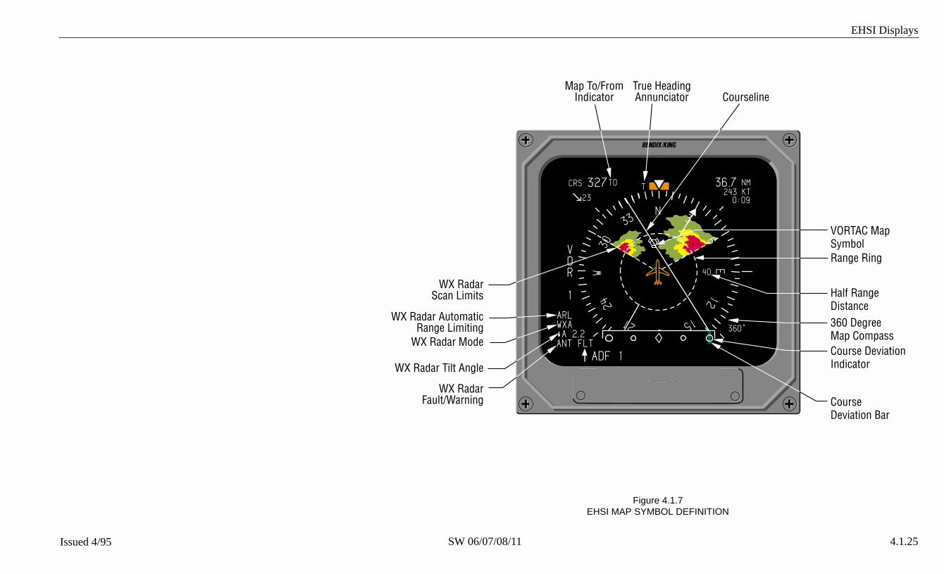
EHSI Displays
SW 06/07/08/11Issued 4/95 4.1.25
Figure 4.1.7EHSI MAP SYMBOL DEFINITION
1
ADF 1
VOR
1
23
CRS 327 36.7 NM
N33
30W
24
21 S15
12E
6
3
TO
ARLWXA
ANT FLTA 2.2
243 KT
40
T
360°
Map To/FromIndicator
VORTAC MapSymbolRange Ring
Half RangeDistance360 DegreeMap Compass
CourseDeviation Bar
WX RadarScan Limits
WX Radar AutomaticRange Limiting
WX Radar Mode
WX Radar Tilt Angle
WX RadarFault/Warning
True HeadingAnnunciator
Course DeviationIndicator
Courseline
0:09

EHSI Displays
SW 06/07/08/11Issued 4/95 4.1.26
Figure 4.1.8EHSI MAP SYMBOL DEFINITION
1
ADF 1
VOR1
23
CRS 327 36.7 NM
N33
30W
24
21 S15
12E
6
3
TO
A 2.2
243 KT
40
T
360°
WX FLTWX OFFWAITRANGESTB LMT429 FLT
WXWXAMAPSTBYTESTBlank
ARLBlank
TOFR
ANT FLT
ANT FLTTX FLTRANGESTB OFFBlankBUSY VP
0:09
NNN
N ONARLWXA
ONOFFFLT
LEVEL 1Lightning
cell
LEVEL 2Lightning
cellLEVEL 3Lightning
cell

EHSI Displays
SW 06/07/08/11Issued 4/95 4.1.27
Figure 4.1.9EHSI ARC MAP SYMBOL DEFINITION
1
VOR1
CRS 340 36.7 NM
N
33 3
243 KT
90°
40
36.7 NMVOR 1
ADF 2
ARLWXA
ANT FLTA 2.2
23
Off ScaleHeading BugRead Out
CourseDeviation
Scale
CourseDeviation
Bar
To/FromPointer
Auto TiltAnnunciator
Arc Compass Card
0:09
N ON

EHSI Displays
SW 06/07/08/11Issued 4/95 4.1.28
Figure 4.1.10EHSI CAT II SYMBOLOGY
1
LOC
1
23
CRS 359 6.2 NM
N33
30W
24
21 S15
12E
6
3
117.95 H
30.8 NMVOR 2ADF 1
360°
GS
VERTICAL EXCESSIVEDEVIATION ARROWS
HORIZONTAL EXCESSIVEDEVIATION ARROWS
CAT II
CAT II ANNUNCIATION

EADI Displays
4.2.1Issued 4/95 SW 06/07/08/11
PITCH ATTITUDE
A moving white simulated hori-zon line rotates angularly with theroll of the aircraft and moves upand down with the pitch of theaircraft. Blue sky above the hori-zon and brown ground below thehorizon align with the horizon lineas it follows the aircraft’s pitchand roll. Pitch scale referencemarks extend above and belowthe horizon line indicating 5,10,15, 20, 25, 30, 35, 40, 45, 50, 55,60, 65, 70, 75, 80 and 90degrees. Refer to Figure 4.2.3.
In the event of a pitch or roll atti-tude failure, the pitch scale, rollscale, roll index pointer, blue skyand brown ground are removedfrom the display. Centered justbelow the roll scale, a RED“ATTITUDE FAIL” enclosed in aRED box will be annunciated.
ROLL ATTITUDE
The roll attitude display for theLear 31A is a movable index (skypointer).
The roll scale provides referencemarks at 10, 20, 30, 45 and 60degrees. To allow easier recogni-tion of the 30, 60 and 45 degreemarks, the 30 and 60 degreemarks are longer extending fur-ther into the center of the displayand the 45 degree mark is dis-
played in the form of a hollow tri-angle. Refer to Figure 4.2.4.
❏ An optional configuration item,selected at the time of installationand certification, allows the EFS50 to declutter nonessential navi-gation data in the event anunusual attitude is encountered.Removal of the data will occur ifpitch angle exceeds +30 or -20degrees, or if bank angleexceeds 65 degrees. Redchevrons, used to indicate thebest unusual attitude recoverydirection (not necessarily rightside up), will appear in the brownground raster between 40 and 85degrees, and in the blue skyraster between 50 and 85degrees.
In the event of a pitch or roll atti-tude failure, the pitch scale, bluesky, brown ground and sky point-er are removed from the display.Centered just below the roll scalea RED “ATTITUDE FAIL”enclosed in a RED box will beannunciated.
ROLL INDICATOR
The sky pointer roll indicator is awhite triangular pointer posi-tioned just below the roll scale.The pointer rotates with the pitchscale while the roll scale remainsfixed.
EADI DISPLAYS
NORMAL ATTITUDE DISPLAY

EADI Displays
4.2.2 Issued 4/95SW 06/07/08/11
Level Attitude
20° Right RollSKY POINTER ROLL SCALE
In the event of an attitude failure,the roll indicator is removed fromthe display.
PERSPECTIVE LINES
❏ A display option selected atthe time of installation and certifi-cation. Orange lines extending30 and 45 degrees downwardfrom the center of the horizon lineprovide additional pilot cues insteep turns. Refer to Figure4.2.4.
Note: The display of perspec-tive lines with the delta shapedaircraft symbol is not accept-able to some certif icationagencies.
SYMBOLIC AIRCRAFT
Located in the center of the dis-play is the fixed orange aircraftsymbol. The pitch and roll atti-tudes of the aircraft are displayedby the relationship of the fixedsymbolic aircraft and the mov-
able horizon. The symbolic air-craft is flown to satisfy the com-mand cues of the flight director.
The EFS 50 offers two symbolicaircraft symbols, the Bull’s Eyeand Delta. Selection of the singlecue command bars will present adelta aircraft symbol, while selec-tion on the double cue commandbars will provide a traditionalbull’s eye aircraft symbol.
Aircraft Reference Delta
Aircraft Reference Bull’s Eye
HEADING TAPE
❏ An optional configuration item,selected at the time of installationand certification, allows a whiteheading tape to be fixed alongthe top of the horizon line. Indexmarks appear every 5 degreeswith heading annunciation dis-played every 30 degrees. Theheading tape can be configuredwith or without a heading bug.
In the event heading databecomes unavailable or invalid, astationary RED “HDG” enclosedin a RED box will be displayedabove and to the right of thesymbolic aircraft.
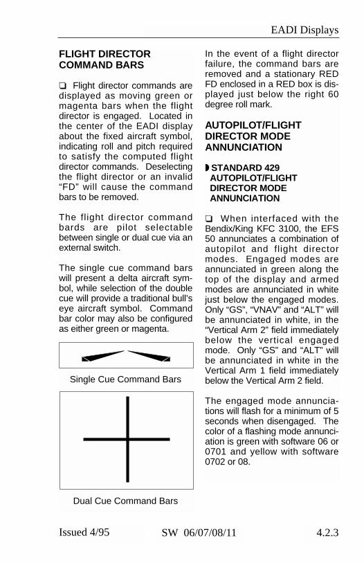
EADI Displays
4.2.3Issued 4/95 SW 06/07/08/11
FLIGHT DIRECTORCOMMAND BARS
❏ Flight director commands aredisplayed as moving green ormagenta bars when the flightdirector is engaged. Located inthe center of the EADI displayabout the fixed aircraft symbol,indicating roll and pitch requiredto satisfy the computed flightdirector commands. Deselectingthe flight director or an invalid“FD” will cause the commandbars to be removed.
The flight director commandbards are pilot selectablebetween single or dual cue via anexternal switch.
The single cue command barswill present a delta aircraft sym-bol, while selection of the doublecue will provide a traditional bull’seye aircraft symbol. Commandbar color may also be configuredas either green or magenta.
Single Cue Command Bars
Dual Cue Command Bars
In the event of a flight directorfailure, the command bars areremoved and a stationary REDFD enclosed in a RED box is dis-played just below the right 60degree roll mark.
AUTOPILOT/FLIGHTDIRECTOR MODEANNUNCIATION
◗ STANDARD 429AUTOPILOT/FLIGHTDIRECTOR MODEANNUNCIATION
❏ When interfaced with theBendix/King KFC 3100, the EFS50 annunciates a combination ofautopilot and flight directormodes. Engaged modes areannunciated in green along thetop of the display and armedmodes are annunciated in whitejust below the engaged modes.Only “GS”, “VNAV” and “ALT” willbe annunciated in white, in the“Vertical Arm 2” field immediatelybelow the vertical engagedmode. Only “GS” and “ALT” willbe annunciated in white in theVertical Arm 1 field immediatelybelow the Vertical Arm 2 field.
The engaged mode annuncia-tions will flash for a minimum of 5seconds when disengaged. Thecolor of a flashing mode annunci-ation is green with software 06 or0701 and yellow with software0702 or 08.
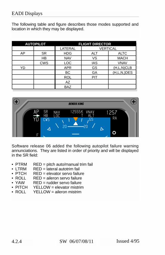
EADI Displays
4.2.4 Issued 4/95SW 06/07/08/11
The following table and figure describes those modes supported andlocation in which they may be displayed.
Software release 06 added the following autopilot failure warningannunciations. They are listed in order of priority and will be displayedin the SR field:
• PTRM RED = pitch auto/manual trim fail • LTRM RED = lateral autotrim fail • PTCH RED = elevator servo failure • ROLL RED = aileron servo failure • YAW RED = rudder servo failure • PITCH YELLOW = elevator mistrim • ROLL YELLOW = aileron mistrim
AUTOPILOT FLIGHT DIRECTOR
AP
YD
LATERALHDGNAVLOCAPRBC
ROLAZ
BAZ
VERTICALSRHB
CWS
ALTVSIASGSGAPIT
ALTCMACHVNAV
(H,L,N)CLB(H,L,N,)DES
1
F
KT
RA
20 20
12555LOCHB
CWS
SR NAV VNAVAP
YD
1257ALTGS

EADI Displays
4.2.5Issued 4/95 SW 06/07/08/11
If the flight director data becomesinvalid, a RED “FD” enclosed in aRED box will be displayed at theright center of the display.
If the autopilot has been on andthen disengaged, a RED “AP” willbe annunciated in the upper lefthand corner of the display. TheRED “AP” will flash when disen-gaged.
Dual autopilot installations, theactive side is annunciated by agreen “AP” and the inactive sidewill be annunciated by a yellow“AP” with a yellow arrow pointingtoward the active side.
Yaw damper “YD”, if engaged,may flash RED when disconnect-ed.
The following autopilot commandreference data will be displayedin green when interfaced with theKFC 3100:
• AIRSPEED60 to Vmo in 1KTincrements.
• MACH.5 to Mmo in 0.005Mincrements.
• VERTICAL SPEED+/-7,000F/M in 100F/Mincrements.
• ALTITUDE0 to 65536FT in 10FTincrements.
• HIGH PROFILE“H”
• NORMAL PROFILE“N”
RADIO ALTIMETER
❏ The radio altimeter display iscomposed of three elements;radio altimeter (RA) height, deci-sion height (DH) set and decisionheight (DH) alert. In the upperright corner of the display, a fieldof white alphanumeric data pro-vides radio altimeter height andannunciation. In the lower rightcorner of the display, a greenalphanumeric field displays theselected DH. This field is activeonly when the DH set knob isactive or when the radio altimeteris providing valid height data. Tothe right and above center of thedisplay, a yellow “DH” alert is dis-played in a black box outlined inyellow.
Radio altimeter (RA) height dis-play range is -20 to 2,500 feet.Between -20 and 100 feet, heightwill be displayed in five foot incre-ments. Above 100 feet, heightwill be displayed in 10 foot incre-ments. Selection of decisionheight and activation of “DH” alertwill be in 1 foot increments. Themaximum and minimum heightdisplayed will depend on theradio altimeter installed.
To annunciate an operationalradio altimeter which has notacquired a valid groundresponse, three white dashes areplaced in the height data field. Ifthe radio altimeter has failed,three RED dashes are placed inthe height data field. In eithercase, if the rising runway is dis-played, it will remain fixed at the
EADI Displays
4.2.6 Issued 4/95SW 06/07/08/11
bottom of its scale and moveslaterally to indicate the LOC orMLS deviation.
DECISION HEIGHT SET
A part time green alphanumericreadout, located in the lower rightcorner, displays the letters DHand selected decision height infeet as manually established bythe DH set control knob. Withthe control pulled out, the DH setvalue is displayed and may beset regardless of aircraft altitude.With the control knob “in”, DH isdisplayed only for radio altimeteraltitude less than 2500 feet AGL.The DH set display range is from“OFF” (-1 ft.) to the RA decluttervalue (2,500’). Refer to Figure4.2.2.
DECISION HEIGHT ALERT
When the radio altimeter heightis equal to or less than the select-ed decision height, the DHannunciator will be displayed.When first activated, the DHannunciator will flash for 10 sec-onds. The DH symbol is a largeyellow “DH” on a black back-ground enclosed by a yellow box,located to the right of the pitchscale and above the horizon linewhen in normal attitude. Refer toFigure 4.2.2.
PRECISION APPROACHMODE FORMAT
The precision approach modedisplay is obtained by selectingan ILS or MLS navigation source.
On the ED 551A used as theEADI, the full sky/ground displayis reduced in size to provide ahigh contrast black backgroundfor various scales and annuncia-tions. A rising runway symbol isprovided for the display ofexpanded left/right deviation andrunway closure during the final200 feet of radio altimeter height.The rising runway center line, ref-erenced to the lateral deviationscale, will provide LOC or MLSdeviation. A “LOC” or “MLS”annunciation identifies the navi-gation mode. A vertical scale isprovided to display ILS or MLSglide path. Refer to Figure 4.2.2.After software release 07 “LOC”or “MLS” are only annunciatedwhen both approach sensors areinstalled. If only one type isinstalled, the lateral deviationscale will not annunciate the nav-igation mode.
EXPANDED LATERALDEVIATION SCALE
Located at the bottom center ofthe EADI, displayed in white, with4 hollow circles and a center dia-mond is the expanded lateraldeviation scale. This scale pro-vides a reference for ILS or MLSlateral deviation. As an expand-ed scale, it represents 1/2 fullscale deviation as displayed onthe EHSI. When the selectedcourse and aircraft heading differby more than 105 degrees, theleft/right sensitivity is reversedand a green (onside) or yellow(offside) BC is displayed left ofthe center diamond to alert the

EADI Displays
4.2.7Issued 4/95 SW 06/07/08/11
pilot that back course informationis being displayed. Refer to Fig-ure 4.2.3 and 4.2.4.
Software version 07 and higherwill display the expandedLOC/MLS scale as three dots.
Note: Warning, some conven-tional ADI expanded ILS andMLS displays represent 1/4 ofthe full scale displayed by theHSI. The EFS 50 provides 1/2the EHSI displayed deviationto provide better pilot interface.
RISING RUNWAY
Three configuration options areselectable at the time of installa-tion and certification for display ofthe rising runway symbol.
❏ The first option provides fulltime display of the rising runwayonly when in the precisionapproach mode. The symbolicrising runway will be displayed inthe lower center of the displayjust above the LOC/MLS lateraldeviation scale. The center lineof the symbolic rising runway rep-resents ILS or MLS fly to com-mand. If the radio altimeter pro-vides height above the groundinformation to the EFS 50, therising runway symbol will startincreasing in size at 200 feet andwill continue to increase in size to0 feet. When the on-side ILS orMLS is selected as the primaryNAV sensor, the rising runwaywill be green in color. If the off-side sensor is selected, the run-way will change to yellow, alert-
ing the pilot that he has selectedoff-side information.
❏ A second configuration optionprovides for the display of a tradi-tional deviation bar in place of therising runway. The deviation barwill overlay the lateral deviationscale. It will not be positionedjust above the deviation scale asthe rising runway is.
❏ A third configuration optionallows the display of the risingrunway unless one of the follow-ing conditions exists, in whichcase the deviation bar will be dis-played.
• No radio altimeter• Radio altimeter is not being
displayed, above 2,500 feet ornot providing computed data
• Radio altimeter is below mini-mum altitude, white dashesdisplayed
• Radio altimeter is flagged, REDdashes displayed.
In the event the lateral deviationinformation becomes invalid orfailed, the rising runway or D barand lateral deviation scale areremoved, the lateral deviationscale is replaced with a RED “X.”
Software version 07 replaces the5 dot expanded localizer scalewith a 3 dot expanded localizerscale whenever the rising runwayis displayed.

EADI Displays
4.2.8 Issued 4/95SW 06/07/08/11
GLIDESLOPE/VERTICALNAVIGATION
When the selected primary NAVsensor is ILS, MLS or LNAV withVNAV selected, a stationarywhite vertical deviation scale willappear on the right or left side ofthe EADI display as configured atthe time of installation and certifi-cation. This scale provides a ref-erence for the vertical deviationpointer. The deviation pointermoves in relation to the scale toindicate glide path center withrespect to aircraft position.
When the on-side sensor isselected for display, the deviationpointer is green in color. Whenthe off-side sensor is selected fordisplay, the deviation pointerchanges to yellow alerting thepilot that he has selected his off-side nav sensor.
If the selected sensor is ILS orMLS, a “GS” (or “GP” for MLSwith SW 08) will be displayed inthe pointer. “VN” will be annunci-ated if the selected sensor is anLNAV with VNAV selected.
Additional configuration optionsselectable at the time of certifica-tion:
❏ Declutter GS on Back Course,allows the vertical deviation scaleto be in view at all times or onlywhen the selected course is with-in 105 degrees of the aircraftheading.
❏ Vertical Scale Side, allows thevertical deviation scale to be dis-
played on either the right or leftside of the EADI and EHSI dis-play.
❏ Vertical pointer annunciationfor MLS can be “GS” or “GP” withsoftware 08.Vertical Pointer Type selected atthe time of certification.
MARKER BEACONANNUNCIATION
In the lower left corner, markerbeacon information is displayedinside a hexagon shaped box.The outer marker, “OM” is dis-played in cyan. The middle mark-er, “MM” is displayed in orange.The inner marker, “IM” is dis-played in white. All three mark-ers may be displayed simultane-ously. Flashing of the markerdisplay is also possible providingthe marker receiver flashes itsoutput.
FAST/SLOW
An optional display item,selectable at the time of installa-tion and certification. If config-ured, will be displayed on theopposite side of the EADI fromthe Glideslope scale. The scaleconsists of two vertical whiteunfilled diamonds and one whiteunfilled circle.
When Fast/Slow is configured,the scale and pointer will be dis-
GS

EADI Displays
4.2.9Issued 4/95 SW 06/07/08/11
played when the airspeed is lessthan 50 knots or less than 0.45mach from the airspeed bugselected setting. The scale andpointer will be removed when theairspeed is greater than 50 knotsor 0.45 mach from the airspeedbug. The scale provides ±10knots indication and ±13 knotsfull scale deflection. AS will beannunciated in the pointer.
Configuration options selectableat the time of installation and cer-tification:
❏ Display of Fast/Slow on thedisplay.
Three pointer styles are provid-ed. Color will be green and thestyle will match the GS pointer.
If invalid or failed sensor data isreceived the deviation pointerand scale are removed and aRED X annunciated.
RATE OF TURN DISPLAY
❏ An optional display item,selectable at the time of installa-tion and certification, if config-ured, will be displayed at the bot-tom center of the EADI. The rateof turn scale is composed ofthree evenly spaced unfilledwhite rectangles. The rate of turnpointer is an equally sized whitefilled rectangle balanced atop asmaller white filled rectangle. Astandard rate turn of 3˚ per sec-ond is indicated when the pointeris directly below the left or rightrectangle.
The rate of turn indicator will notbe displayed when the compositereversionary mode is selected fordisplay.
If rate of turn data becomesinvalid, the pointer and scale willbe removed and replaced with aRED “X”.
❏ Beginning with softwarerelease 0702, configuration itemsare provided for bank angle cor-rection of the yaw rate gyro. Thiscorrection takes into account theaircraft roll attitude when display-ing rate of turn information.
CATEGORY IIANNUNCIATOR
Refer to Figure 4.2.7 whilereviewing this section.
❏ An optional annunciator pro-vides advisory only information,selectable at the time of installa-tion and certification. When con-figured, the symbol generator willmonitor the appropriate on-sideand cross-side information andalert the crew when Category IIrequirements or limits are not sat-isfied.
The Category II Annunciator pro-vides different limits for FAR andJAR-AWO certifications.
◗CATEGORY II OPERATIONANNUNCIATIONS
Special requirements and equip-ment are required for CAT IIoperation.

EADI Displays
4.2.10 Issued 4/95SW 06/07/08/11
Activation of the remote CategoryII switch by the pilot will cause ayellow CAT II to be displayed onthe ADI and HSI to indicate thatCategory II annunciations areactive. The remote Category IIselection switch will be a momen-tary contact type for software 06and 0701, but must be alternateaction for software 0702 and 08(or later). Category II can beactivated at any time and in allnormal modes of the EFS.
In the normal sequence ofevents, a white CAT II will be dis-played on the ADI and HSI inplace of the previous yellow CATII only when certain criteria aremet:
The following requirements mustbe met in a four or five tube EFSsystem before the Category IIannunciator will change to white:
1. Valid ILS or MLS #1 is select-ed on Symbol Generator #1.
2. Valid ILS #2 is selected onSymbol Generator #2.
3. Valid ATT #1 is selected onSymbol Generator #1.
4. Valid ATT #2 is selected onSymbol Generator #2.
5. Valid HDG #1 is selected onSymbol Generator #1.
6. Valid HDG #2 is selected onSymbol Generator #2.
7. Pilot and copilot symbol gen-erator are valid.
8. Both crosstalk buses arevalid.
9. SG3, composite or ADI-downmodes are not active.
10. Radio altitude is valid and
between 2,500 feet and 50feet.
11. True heading is not active.12. Valid pilot flight director.13. Pilot’s command bars in
view.14. No attitude, heading, localiz-
er, glideslope or radio altitudemiscompare flags.
15. Front course ILS or MLSapproach.
16. Pilot’s flight director (if avai-able) engaged in localizerand glideslope.
Additional requirements to beadded to the above criteria ifapplicable:
• Both pilot and copilot ILS #1and #2 frequencies mustmatch if known and valid.
• Both pilot and copilot MLS #1and #2 channels must match ifknown and valid.
• Valid copilot flight director ifconfigured.
• Copilot’s flight directorengaged in localizer andglideslope if FD configured.
• Copilot’s command bars inview if FD configured.
With software 06 and 0701, agreen CAT II will be displayed inplace of the white CAT II on theADI and HSI when the above cri-teria are met and the radioaltimeter is between 500 and 100feet. An additional requirementwith software 0702 and 08 is forthe excessive deviation monitorto be within the configured limitsbefore the “CAT II” annunciationcolor changes to green. Green

EADI Displays
4.2.11Issued 4/95 SW 06/07/08/11
excessive deviation arrows(>> <<) will appear on the ADIand HSI localizer and glideslopescales. If the rising runway isconfigured for display, greenchevrons will be displayed withinit. Location of the excessive devi-ation arrows on the localizer andglideslope scales will be dis-played according to the CategoryII limits.
Yellow flashing arrows on thelocalizer scales and yellow flash-ing chevrons on the rising run-way will be displayed if the local-izer pointer exceeds the limits setby the arrows(>> <<).
Yellow flashing arrows on theglideslope scales and yellowflashing GS in the glideslopepointer will be displayed if theglideslope pointer exceeds thelimits set by the arrows(>> <<).
All yellow excessive deviationsymbols will flash.
White CAT II will be displayedbelow 100 ft., and no excessivedeviation symbology will be dis-played.
Yellow CAT II will be displayedbelow 50 ft., and no excessivedeviation symbology will be dis-played.
◗CATEGORY II THRESHOLDS
The following Category II limits are for the comparison of excessivedeviation and for the placement of the deviation scale arrows.
CONDITIONS DEVIATIONLIMITS (µa)
EFSSOFTWARE
DEVIATION RADIOALTITUDE
APPROACHTYPE
FAR JARold
JARnew
06010701
07020801
LocalizerLocalizer
GlideslopeGlideslope
500 to 300 ft300 to 100 ft
500 to 100 ft500 to 100 ft
AP/FDAP/FD
APFD
LocalizerLocalizer
Glideslope
500 to 300 ft300 to 100 ft
500 to 100 ft
AP/FDAP/FD
AP/FD
3525
3575
2525
7575
3525
75
2020
65
2525
75
CATEGORY II DEVIATION LIMITS

EADI Displays
4.2.12 Issued 4/95SW 06/07/08/11
Note: FAR localizer limits willchange on init ial 300 feetcrossing and will remain atnew limits.
An additional configuration optionprovided with 0702 and 08 soft-ware allows CAT II operationwithout any deviation monitoring.
When activated, Category II devi-ation limit (>> <<) indicators aredisplayed on the glideslope andlocalizer scale, chevrons will alsobe displayed on the rising runwayif it is configured for display.
ATTITUDE MONITOR
Dual channel processing of Atti-tude inputs provides validation ofthe processed displayed attitudeinformation within the symbolgenerator. If a failure is detectedin the processed information,“ATTITUDE FAIL” is annunciatedat the top center of the displayand blue sky and brown groundinformation and associated atti-tude scales are removed.NOTE: There is no monitor func-tion in any reversionary mode.
CROSS COMPARATORANNUNCIATORS
Refer to Figure 4.2.5 whilereviewing this section.
Provides system comparisonbetween like on-side and off-sidesensors. The following listdescribes the associated symbol-ogy and sensors:
◗RA
Radio altitude miscompare, a yel-low RA above a double-endedarrow displayed just below theradio altitude readout in theupper right corner. This is dis-played when SG 1 and SG 2radio altitude differ by more than8 feet at between 0 and 99 feetAGL. The Allowable differenceincreases by 8 ft per 100 ft of alti-tude . If the off-side RA flag is dif-ferent the miscompare will alsobe displayed.
◗LOC
Localizer miscompare, a double-ended arrow will be displayedover the localizer deviation point-er on the EADI and EHSI whenboth SG 1 and SG 2 are tuned toan ILS/MLS frequency and differby more than halfscale deviation.
◗GS
Glideslope miscompare, a dou-ble-ended arrow will be displayedabove the glideslope deviationpointer on the EADI and EHSIwhen both SG 1 and SG 2 aretuned to an ILS/MLS frequencyand differ by more than halfscale.
◗ATT
Attitude miscompare, a yellowdouble-ended arrow over “ATT”will be displayed in the top leftcorner of the EADI if ADI pitch 1,2, and cross-side (if available)differ by more than 5 degrees orroll 1, 2, and cross-side (if
EADI Displays
4.2.13Issued 4/95 SW 06/07/08/11
available) differ by more than 6degrees. The miscompare willalso be displayed if the failurewarning flags differ.
Note: In reversionary modesthe EHSI Attitude may beused for comparison ifrequired.
◗HDG
Heading miscompare, a yellowdouble-ended arrow over “HDG”will be displayed to the left of thelubber on the EHSI and right sidecenter of the EADI if heading 1, 2and cross-side (if available) differby more than 6 degrees up to 6degrees of bank and by morethan 20 degrees above 6degrees of bank. If bank infor-mation is not available, the mis-compare will be displayed ifheading differs by more than 20degrees. The miscompare willalso be displayed if the failurewarning flags differ. Headingmiscompare will be processed inthe EHSI section of the symbolgenerator and displayed on theEADI if the heading tape isselected for display. Headingmiscompare will not be per-formed if sources are not typematched (all magnetic or all true).
Note: Beginning with software11, SG1 to SG2 comparisons ofattitude, heading, and radioaltitude are not performed if validdata is not available on the cross-talk bus between symbol genera-tors. Therefore, failure of an SGin installations with both SG1 and
SG2 configured can cause mis-compare annunciations only withsoftware versions before 11.

EADI Displays
4.2.14 Issued 4/95SW 06/07/08/11
*This page intentionally left blank.

EADI Displays
SW 06/07/08/11Issued 4/95 4.2.15
Figure 4.2.1TYPICAL EADI 50 DISPLAY
1
63N T
20 20
10 10
10 10
20 20
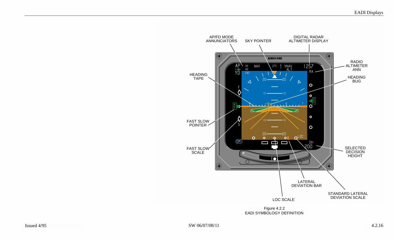
EADI Displays
SW 06/07/08/11Issued 4/95 4.2.16
Figure 4.2.2EADI SYMBOLOGY DEFINITION
ı
F
S
6
KT
3N T
RA
20
10
20
10
20
10
20LOC
DH
10
275
HB
CWS
SR NAV VNAVAP
YD
1257
200OM
ALT
AP/FD MODEANNUNCIATORS
HEADINGTAPE
FAST SLOW SCALE
FAST SLOW POINTER
SELECTEDDECISIONHEIGHT
STANDARD LATERALDEVIATION SCALE
LATERALDEVIATION BAR
LOC SCALE
RADIOALTIMETER
ANN
SKY POINTERDIGITAL RADAR
ALTIMETER DISPLAY
AS
GS
HEADINGBUG

EADI Displays
SW 06/07/08/11Issued 4/95 4.2.17
Figure 4.2.3EADI SYMBOLOGY DEFINITION
ı
F
S
6
KT
3N T
RA
20
10
20
10
20
10
20LOC
DH
10
12555
LOCHB
CWS
SR NAV VNAVAP
YD
1257
200
AP MODES
LATERALFD/AP MODE
AP COMMANDDATA
VERTICAL FD/APMODES
VERTICALDEVIATIONPOINTER
VERTICALDEVIATION
SCALE
EXPANDED LATERALDEVIATION SCALE
RISING RUNWAYLATERAL DEVIATIONPITCH SCALE
SINGLE CUEFD COMMAND
BARS
AS
GS
ALTGS

EADI Displays
SW 06/07/08/11Issued 4/95 4.2.18
Figure 4.2.4EADI SYMBOLOGY DEFINITION
ı
F
S
6
KT
3N T
RA
20
10
20
10
20
10
20LOC
DH
10
12555
LOCHB
CWS
SR NAV VNAVAP
YD
1257
200
IM
SINGLE CUEFLIGHT DIRECTORCOMMAND BARS HORIZON LINES
WITH HEADINGTAPE
PERSPECTIVELINES
SINGLE CUEDELTA AIRCRAFT
SYMBOL
SCALEANNUNCIATOR
EXPANDED LATERALDEVIATION SCALE
ALTGS
AS
GS

EADI Displays
SW 06/07/08/11Issued 4/95 4.2.19
Figure 4.2.5EADI SYMBOLOGY DEFINITION
ı
F
S
6
KT
3N T
RA
20
10
20
10
20
10
20LOC
SG
DH
10
SG 3
COPY
275
HB
CWS
SR NAV
ATT1
VNAVAP
YD
ATT
1257
1300
HDG1 HDG
IMMMOM
ALT
DH
CHECK CONFIG
CHECKCONFIGURATION
MESSAGE RADIO ALTIMETERMISCOMPARE
DECISIONHEIGHT ALERT
GLIDE SLOPEMISCOMPARE
HEADINGMISCOMPARE
RATE OF TURNPOINTERLOCALIZER
MISCOMPARE
RATE OF TURNSCALE
MARKERS
HEADINGSELECT
FLAG
ATTITUDESELECT
FLAG
ATTITUDEMISCOMPARE
AS
GS

EADI Displays
SW 06/07/08/11Issued 4/95 4.2.20
Figure 4.2.6EADI FAULTS SYMBOLOGY
ı
F
S
6
KT
3N T
RA
20
10
20
10
20
10
20LOC
DH
10
12555
APRHB
CWS
SR NAV
HDG
VNAVAP
YD
---
200
ATTITUDE FAIL TEST
FD
ALT
ATTITUDE FAILANNUNCIATOR
FLIGHT DIRECTORFAILURE
ANNUNCIATOR
HEADING FAILUREANNUNCIATOR
FLIGHT TEST MODEANNUNCIATOR
CONTROL PANELFLAG
SG FLAG
DISPLAY UNITFAN FLAG
SG FANFLAG
CP DU
SGSG
AS
GS

EADI Displays
SW 06/07/08/11Issued 4/95 4.2.21
Figure 4.2.7CAT II SYMBOLOGY
ı
N33
RA
20
10
20
10
20
10
20LOC
DH
10
200
CAT II
DH
AP LOC GS 100
CAT II RISINGRUNWAY CHEVRONS
LATERAL EXCESSIVEDEVIATION ARROWS
CAT IIANNUNCIATOR
VERTICAL EXCESSIVEDEVIATION ARROWS
GS

EADI Displays
SW 06/07/08/11Issued 4/95 4.2.22
Figure 4.2.8EXAMPLE EADI ENROUTE DISPLAY
WITH 08 SOFTWARE
ı
63N
20
10
20
10
20
10
20
10
KT
RA
275HB
CWS
SR NAV VNAV 2490ALT
AP
YD
F
AS
S
DH
200

EADI Displays
SW 06/07/08/11Issued 4/95 4.2.23
Figure 4.2.9EXAMPLE EADI APPROACH DISPLAY
WITH 08 SOFTWARE
ı
OM
63N
20
10
20
10
20
10
20
10
LOC
KT
RA
275HB
CWS
SR NAV VNAV 1257ALT
AP
YD
F
AS
S
GS
DH
200
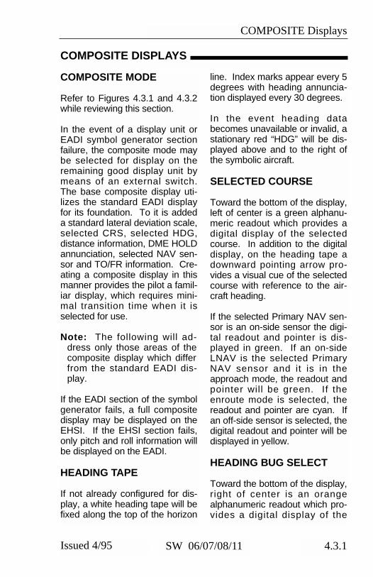
COMPOSITE Displays
4.3.1Issued 4/95 SW 06/07/08/11
COMPOSITE MODE
Refer to Figures 4.3.1 and 4.3.2while reviewing this section.
In the event of a display unit orEADI symbol generator sectionfailure, the composite mode maybe selected for display on theremaining good display unit bymeans of an external switch.The base composite display uti-lizes the standard EADI displayfor its foundation. To it is addeda standard lateral deviation scale,selected CRS, selected HDG,distance information, DME HOLDannunciation, selected NAV sen-sor and TO/FR information. Cre-ating a composite display in thismanner provides the pilot a famil-iar display, which requires mini-mal transition time when it isselected for use.
Note: The following will ad-dress only those areas of thecomposite display which differfrom the standard EADI dis-play.
If the EADI section of the symbolgenerator fails, a full compositedisplay may be displayed on theEHSI. If the EHSI section fails,only pitch and roll information willbe displayed on the EADI.
HEADING TAPE
If not already configured for dis-play, a white heading tape will befixed along the top of the horizon
line. Index marks appear every 5degrees with heading annuncia-tion displayed every 30 degrees.
In the event heading databecomes unavailable or invalid, astationary red “HDG” will be dis-played above and to the right ofthe symbolic aircraft.
SELECTED COURSE
Toward the bottom of the display,left of center is a green alphanu-meric readout which provides adigital display of the selectedcourse. In addition to the digitaldisplay, on the heading tape adownward pointing arrow pro-vides a visual cue of the selectedcourse with reference to the air-craft heading.
If the selected Primary NAV sen-sor is an on-side sensor the digi-tal readout and pointer is dis-played in green. If an on-sideLNAV is the selected PrimaryNAV sensor and it is in theapproach mode, the readout andpointer will be green. If theenroute mode is selected, thereadout and pointer are cyan. Ifan off-side sensor is selected, thedigital readout and pointer will bedisplayed in yellow.
HEADING BUG SELECT
Toward the bottom of the display,right of center is an orangealphanumeric readout which pro-vides a digital display of the
COMPOSITE DISPLAYS

COMPOSITE Displays
4.3.2 Issued 4/95SW 06/07/08/11
selected heading. In addition tothe digital display, on the headingtape is a hollow orange headingbug which provides a visual cueof the selected heading with ref-erence to the aircraft heading.
Note: As the aircraft headingchanges, the selected coursepointer and heading bug willfollow the heading tape andmay disappear from view. Theheading bug and course point-er function the same as theydo in the normal mode of oper-ation, once set they are fixedto the heading tape or com-pass card.
NAVIGATION SOURCEANNUNCIATION
A vertical three- or four-letteralphanumeric readout located onthe left or right side of the dis-play, depending on vertical scaleside selection, indicates the navi-gation selected as the primarynavigation sensor.
Green annunciations indicate anon-side approach NAV system isbeing displayed. Yellow indi-cates the cross-side system hasbeen selected. Cyan annuncia-tions apply to on-side non-approach NAV systems. Thesecolor codes apply to the NAVsource annunciator, CRS pointer,deviation bar, CRS, and dis-tance.
If both sides select the samenavigation source (i.e., pilot andcopilot select VOR 2) a yellow
box is placed around the naviga-tion source annunciator on bothsides of the cockpit.
If both sides select their respec-tive cross-side navigation source(i.e., pilot selects system 2, copi-lot selects system 1) then bothNAV source annunciators will beyellow with no yellow box.
LATERAL COURSEDEVIATION SCALE(Non Approach Mode)
Located at the bottom center ofthe EADI, displayed in white, withfour hollow circles and a centerdiamond is the lateral deviationscale. The course deviationscale provides a reference for thecourse deviation bar to indicatethe centerline of the selectednavigation or localizer or MLScourse in relation to the centerdiamond.
The course width displayed in thecomposite mode is identical tothat typically shown on the EHSI.
LATERAL COURSEDEVIATION BAR
The course deviation bar repre-sents the centerline of the select-ed navigation or localizer course.
If invalid or failed primary NAVsensor data is received thecourse deviation bar and scaleare removed and a RED Xannunciated.
COMPOSITE Displays
4.3.3Issued 4/95 SW 06/07/08/11
Beginning with software 11, thedeviation bar and scale aredecluttered when lateral devia-tion information is provided inARINC 429 format with a statusof No Computed Data (NCD).The red “X” is still displayed forinvalid or missing data.
TO/FROM
Displayed left of the center dia-mond on the lateral deviationscale, a white “TO” or “FR” willprovide TO/FROM informationwhen in non-ILS or non-MLSmodes.
DISTANCE INFORMATION
An alphanumeric readout, locat-ed in the lower left corner, annun-ciates distance in nautical milesfrom the aircraft to the selectedprimary NAV station when in theVOR, TACAN, ILS or MLS mode,or to the waypoint in the LNAV orRNAV mode.
DME HOLD
When DME HOLD is selected,the DME distance and annuncia-tor color will change to white andwill remain white until the HOLDfunction is released. The sensoridentifier (ADF, VOR, ILS, etc )shall retain the original assignedcolor. The HOLD function isadditionally annunciated by anorange letter “H” displayed imme-diately to the right of the distanceinformation. Ground speed andtime-to-station are not displayedwhile DME HOLD is active
Once the DME is placed inHOLD, its distance will continueto be displayed and will not beaffected when the primary NAVsensor is changed.
DME HOLD will not functionwhen MLS, LNAV or RNAV is theselected sensor. In this situationthe associated distance field isalways used to display waypointor MLS distance.

COMPOSITE Displays
4.3.4 Issued 4/95SW 06/07/08/11
*This page intentionally left blank.

COMPOSITE Displays
SW 06/07/08/11Issued 4/95 4.3.5
Figure 4.3.1COMPOSITE ENROUTE MODE DISPLAY
ı
33 3N
20
10
20
10
20
355 020
175 NMTO
VOR1 10
CRS HDG
20
10

COMPOSITE Displays
SW 06/07/08/11Issued 4/95 4.3.6
Figure 4.3.2COMPOSITE APPROACH MODE DISPLAY
ı
33 3N
20
10
20
10
20
355 020
175 NM
IM
LOC1 10
CRS HDG
20
10
RA100COURSE
POINTER
PRIMARYNAVIGATION
SENSOR
DME/LNAVDISTANCE
SELECTEDCOURSE
SELECTEDHEADING
HEADINGBUG
GS

MFD Displays
4.4.1Issued 4/95 SW 06/07/08/11
The MFD’s primary purpose is toprovide weather radar and/orLNAV moving map information.In addition to providing the tradi-tional display functionality, theEFS 50 MFD also has the abilityto function as an independentEHSI if the system is configuredto provide such functionality.
In such cases, the informationdisplayed on the MFD follows thesame basic display format as theEHSI. Therefore this section willonly address those areas of theMFD that differ from the EHSI.
Refer to the figures at the end ofthis section.
CCRRSS , CRS NOT SELECT
When the MFD course selectknob is not active, a bar the colorof the CRS annunciator will beplaced above it. This will alert thepilot that the MFD CRS knob isnot active and the MFD’s courseannunciator is referenced to thepilot’s EHSI selected course.
Example: CCRRSS 135
WEATHER ONLY
❏ A configuration option avail-able at the time of installation andcertification, provides a traditionalweather radar indicator display.Unlike most conventional EFISweather radar displays this dis-play will not present any nonweather related information. Allnavigation information is
removed, leaving a clean weath-er presentation consisting of fourcyan range rings and white radarannunciations located in thelower left corner.
Weather radar mode, warningsand failure annunciations are dis-played as they are on the normalEHSI ARC Weather mode.
◗TRACK LINE
A yellow dashed line drawn fromthe center of the symbolic aircraftto the compass card or outerrange ring. Activated and slewedby pressing one of the TRK but-tons. Pressing the VP button willactivate VP at the location of theTrack Line. In the upper left cor-ner a yellow digital readout dis-plays the present position of thetrack line. Once the track linehas remained stationary for 15seconds it will be decluttered.
VERTICAL PROFILE (VP)
◗SYMBOLIC AIRCRAFT
When the VP mode is selectedfor display, the symbolic aircraftis centered on the left edge of thedisplay.
◗RANGE RINGS
Four evenly spaced vertical cyanrange rings are displayed duringVP. At the bottom of each rangering, a cyan distance number isdisplayed annunciating it’s range.
MFD DISPLAYS

MFD Displays
4.4.2 Issued 4/95SW 06/07/08/11
◗ALTITUDE LINE
Three horizontal altitude lines arepresent on the VP display. Thecenter line is off the nose (boreline) of the symbolic aircraft, rep-resenting the actual aircraft’s pre-sent altitude. Equally spacedabove and below the 0 foot cen-ter line are two altitude lines acertain number feet above andbelow the aircraft. The numberassociated with these lines varieswith the selected range to com-pensate for the radar beam widthat the various ranges.
◗PROFILE ANGLE
In the upper left corner “PRO-FILE” is displayed annunciatingthat the VP mode is selected.Just below it, the present azimuthangle being sliced is displayed asL (left) or R (right) followed by anumber. “R6” would represent aVP slice being performed at 6degrees right of the aircraft nose.
◗PLAN-VIEW,NORTH-UP MAP
❏ Beginning with software 07Plan-View is an option selectableat the time of installation. ThePlan-View North-Up map modeprovides a display in which asymbolic aircraft shows the actu-al aircraft’s position relative to theLNAV flight plan route. As theactual aircraft progresses alongthe flight plan route or deviatesfrom it, the symbolic aircraft like-wise progresses along or devi-ates from the flight plan depictionon the indicator. Range is depict-ed by the dashed white full scale
range ring and dashed light bluehalf scale range ring. When thePlan-View is first entered, thesymbolic aircraft is positioned inthe center of the display. As theactual aircraft moves, the sym-bolic aircraft will move about thedisplay and may move offscreen. If this occurs, the sym-bolic aircraft can be brought backonto the screen in any of threeways. One is by pressing theenter button. This will repositionthe symbolic aircraft at the centerof the display. Another method isto use the joystick to change thelat/long of the center of thescreen (see Joystick operation inSection 2.4, MFD Operation). Athird method is to select a greaterrange scale.NOTE: Enter and joystick func-tions are only available on theCP 469A.
The Plan-View, always displayedas a true north map, aids in flightplanning and aircraft positionawareness. Weather radar, light-ning and other navigation infor-mation are not available in Plan-View mode.
To display the Plan-View, anLNAV with an active valid flightplan must be selected as the pri-mary navigation source and beproviding valid magnetic varia-tion. The current FROM way-point and the next 14 waypointson the flight plan may be dis-played. As defined for the nor-mal NAV Map, the pilot may electto display either the closestnavaids or airports along with thefirst five flight plan waypoints.

MFD Displays
4.4.3Issued 4/95 SW 06/07/08/11
TCAS INTERFACE
❏ With software 08 and higher aconfiguration option available atthe time of installation and certifi-cation, provides a TCAS ONLYtraffic display on the MFD. A“TRAFFIC” message is providedfor the pilot and co-pilot EHSI dis-plays during an active TA or RA,but intruder traffic will not beshown on these displays, onlythe MFD.NOTE: In some installationsTCAS “TRAFFIC” and statusadvisories may not be displayedon the EHSI’s.
Range control will be retained bythe CP 469A MFD control panel.Above/norm/below and actual/relative altitude selections will bemade on the TCAS control panel.
Resolution advisory (RA) infor-mation such as a climb arrow willnot be shown on the MFD. RAtraffic will be displayed withTCAS II, but not TCAS I.
Whenever a normal operatingmode that does not displayTCAS traffic information is select-ed on an MFD display , “TRAF-FIC” will be annunciated to indi-cate that a TA or RA is inprogress. This annunciation willremain on non-TCAS displays aslong as at least one TA or RA isactive.
All RA, TA, and PROXIMATETRAFFIC will be displayed on theMFD when TCAS is configuredand TCAS ONLY is selected,regardless of display format and
altitude limits. OTHER TRAFFICwithin the selected altitude limitswill also be displayed when pos-sible. The EFS 40/50 will displayup to 20 TCAS intruders on theMFD.
◗TCAS ONLY SELECTION
With EFS software 08 and later,a dedicated TCAS select pushbutton on the CP 469A MFDControl Panel labeled “TCASONLY” will provide 360° TCASONLY (range = 5 nm) on theMFD with a single selection. Thismomentary switch will alternatelyselect TCAS ONLY and last dis-play mode. The last displaymode will be restored exactly,including previous range andmap format.
TCAS and checklist are mutuallyexclusive modes that will canceleach other such that only themost recently selected will beactive.
Default conditions at selection:360° format5 NM rangeAll intruders displayed
(20 max.)Operation while selected:
Ranges available: 2, 5, 10, 20,40 NM
360° format onlyTST/REF, NAV, RMI 1, RMI 2,
ENT, JOYSTICK and 1/2buttons are inactive
De-selection:The dedicated TCAS ONLY
select always returns to the lastdisplay mode.

MFD Displays
4.4.4 Issued 4/95SW 06/07/08/11
◗TCAS DISPLAY FORMAT
TCAS ONLY display will be 360°format and normally contain thefollowing elements:
* Small cyan symbolic aircraftsymbol located in the center ofthe 360° TCAS ONLY display.
* Two NM range ring consistingof cyan dots positioned every30 degrees to represent the 12clock positions is presented on5 NM and 10 NM ranges only.
* Full range ring consisting ofcyan radial tick marks pos-itioned every 30 degrees torepresent the 12 clock pos-itions plus intervening cyandots every 10 degrees.
* Map type half range ring (whitedashes) without range annunc-iation on 20 NM and 40 NMranges.
* “TCAS” annunciation in verticalfield in place of nav source.
* TCAS mode annunciation.* TCAS range annunciation.* Up to two no-bearing intruder
messages.* Above/norm/below annuncia-
tion.* Actual intruder altitude and
(FLXXX) annunciation whenappropriate.
* TCAS traffic symbols (intruder,data tag, and vertical speedarrow).
◗TCAS TRAFFIC SYMBOLOGY
Each intruder symbol will beaccompanied by a data tag and,when appropriate, a verticalspeed arrow. The data tag andarrow will be the same color as
the intruder symbol that they areassociated with. The intrudersymbol, data tag, and verticalspeed arrow will appear thesame size regardless of rangeselection.
Intruder Symbols
NOTE: RA traffic is not provid-ed with TCAS I.
Traffic generating a ResolutionAdvisory (RA) will be displayedas solid red squares. Traffic gen-erating a Traffic Advisory (TA)will be displayed as solid yellowcircles. Proximate traffic will bedisplayed as solid white dia-monds. All other, no threat trafficwill be displayed as hollow (out-line only) white diamonds.Intruder symbols are centered onthe actual intruder location.
Vertical Speed Arrow
The vertical speed arrow will bepositioned immediately to theright of the intruder symbol whenthe intruder vertical trend is climbor descend as reported by theTCAS processor. The arrow willpoint up for climbing traffic anddown for descending traffic.
Data Tag
The data tag will normally consistof a + or - followed by two digitsof altitude difference (relative alti-
RA TA PROXIMATE OTHER
TCAS INTRUDER SYMBOLS
-01+02
-03 -05

MFD Displays
4.4.5Issued 4/95 SW 06/07/08/11
tude) in hundreds of feetbetween the intruder and ownaircraft. (+ = intruder above ownaircraft) During selection of actu-al altitude, and with a validsource of own altitude providedby the TCAS processor, the datatag will consist of three digits rep-resenting hundreds of feet aboveMSL. Actual altitudes below sealevel will be displayed as two dig-its preceded by a minus sign.The data tag will be centered onthe intruder symbol and posi-tioned above it when the intruderis above own aircraft. The datatag will be positioned below theintruder symbol when the intruderis below own aircraft. The rela-tive altitude data tag for intrudersat the same altitude as own air-craft will consist of “00” without a+ or - sign and be positioned toindicate the intruder’s mostrecent altitude deviation fromown aircraft. When no altitudetrend information is available, the“00” is positioned below the trafficsymbol.
Off-Scale Traffic
RA and TA traffic that is locatedbeyond the selected range of aTCAS display will be shown asone half of the appropriate intrud-er symbol located on the outeredge of the displayed area at theproper bearing. A data tagand/or vertical speed arrow asso-ciated with this intruder will retainits normal position relative to theintruder symbol and only thatportion (if any) within the normaldisplay area will be visible.
◗TCAS DISPLAYANNUNCIATIONS
Traffic
During an active RA or TA, a“TRAFFIC” message will beannunciated in large text on theMFD and EHSI. The “TRAFFIC”message will not be displayed onthe MFD if the MFD is in TCASONLY format. This annunciationwill be provided for all normaloperating modes, but not whilemaintenance or configurationpages are displayed. “TRAFFIC”will be red during an active RAand yellow during an active TA(an RA has priority over a TA).This annunciation will not bemade while TCAS is selected fordisplay. Beginning with software0802,the “TRAFFIC” mesage willbe replaced by a "NO TCAS"message for 15 seconds follow-ing a TCAS failure or a change ofTCAS mode to Standby.
NOTE: In some installations aremote annunciator may beinstalled to provide full timeTCAS operational status.
TCAS
TCAS ONLY format will include acyan “TCAS” displayed in thevertical field where the selectednavigation source is normally dis-played in other modes.

MFD Displays
4.4.6 Issued 4/95SW 06/07/08/11
TCAS Status
TCAS mode, range, above/norm/below selection, and actual altitude(FL) selection will be presented in the bottom right corner of the dis-play normally used for the RMI 2 pointer annunciations. FLxxx andABV/BLW are both provided in the same five character field whenspecific conditions are satisfied as shown in the following table.
CONDITIONS TCAS ANNUNCIATION
ABOVEBELOWSELECT
REL/FLALT
SELECT
ValidAltitudeprovided
TCAS MODES(Display priority)
TA/RA
(7)
TAONLY
(6)
TCASSTBY
(5)
NOTCAS
(4)
TCASFAIL(3)
TD FAIL
(2)
TCASTEST(1)
Normal
Above
Below
X
Normal
Above
Below
Relative
Relative
Relative
FL
FL
FL
FL
X
X
X
YES
NO
NO
NO
TA/RA
TA/RAABV
TA/RABLW
TA/RAFL123
TA/RAFL
TA/RAFLABV
TA/RAFLBLW
TA
TAABV
TABLW
TAFL123
TAFL
TAFLABV
TAFLBLW
TCASSTBY
TCASSTBY
TCASSTBY
TCASSTBY
TCASSTBY
TCASSTBY
TCASSTBY
NOTCAS
NOTCAS
NOTCAS
NOTCAS
NOTCAS
NOTCAS
NOTCAS
TCASFAIL
TCASFAIL
TCASFAIL
TCASFAIL
TCASFAIL
TCASFAIL
TCASFAIL
TDFAIL
TDFAIL
TDFAIL
TDFAIL
TDFAIL
TDFAIL
TDFAIL
TCASTEST
TCASTEST
TCASTEST
TCASTEST
TCASTEST
TCASTEST
TCASTEST
ANNUNCIATION COLOR * ** CYAN CYAN YEL YEL CYANX = Doesn't matter.
*TA/RA will be cyan. FL 123 will be white when a valid altitude is available, otherwise FL will be yellow. ABV and BLW will be cyan.**TA (for TA ONLY mode) will be yellow during an active TA and cyan otherwise. FL123 will be white when a valid altitude is available, otherwise FL will be yellow. ABV and BLW will be cyan.
TCAS Mode
TEST - Indicates that the TCASprocessor is performing sys-tem test.
TD FAIL - Indicates that thecapability of the EFS to prop-erly display TCAS traffic issuspect.
TCAS FAIL - Indicates that theTCAS processor (or a TCASantenna) has failed.
NO TCAS - Indicates that aTCAS system component(other than TCAS processorand TCAS antenna) has failed.
TCAS STBY - Indicates thatTCAS has been intentionallyplaced in standby mode.
TA - Indicates that TA ONLYmode has been entered by theTCAS processor. When dis-played, the annunciation colorwill be yellow if any intruder is
TCAS STATUS ANNUNCIATIONS

MFD Displays
4.4.7Issued 4/95 SW 06/07/08/11
a Traffic Advisory (TA). Thecolor will be cyan when thereare no intruders classified as aTA. TCAS I installations willindicate TA during normaloperation.
TA/RA - Indicates normal opera-tion for TCAS II. This annunci-ation will not appear whenTCAS I is installed.
Range
Range is annunciated in cyanwithout an alpha prefix immedi-ately to the left of the TCAS sta-tus information. The ranges avail-able are 2, 5, 10, 20 and 40 NM.
Range Rings
• Full range ring consisting ofcyan radial tick marks positionedevery 30 degrees to representthe 12 clock positions plus inter-vening cyan dots every 10degrees.
• If range is less than 20 NM, atwo NM range ring consisting ofcyan dots positioned every 30degrees to represent the 12 clockpositions.
• If range is greater than 10 NM,a standard map half range ringwith no range annunciation.
• If range is 2 NM, the outerrange ring is replaced with the 2NM range ring consisting of 12dots (and no tic marks) aroundthe circle.
Above/Norm/Below
All TCAS displays will annunciatea cyan “ABV” or “BLW” whenabove or below respectively areselected on the TCAS controller.Neither annunciation is providedwhen normal is selected. Thissame three character field is alsoused to present own aircraft alti-tude when actual altitude (FL) isselected. The FL annunciationhas priority over ABV and BLW.
No-Bearing Traffic
During any TCAS display, up totwo no-bearing traffic messagesmay be required. The format forthese messages is “TA 5.7NM/-06≠” or “RA 0.8NM/+01≠” where -06 and +01 are the relative alti-tudes of the intruder aircraft.Relative altitudes (including the +or - sign) will be replaced by a 3digit actual altitude in hundreds offeet whenever the conditions fordisplay of actual altitude havebeen satisfied. RA messageswill be red and TA messages willbe yellow. The vertical speedarrow, when climb or descend isindicated, will be displayed imme-diately to the right of the altitudedigits.
FLXXX and FL
A white FLXXX is annunciatedonly when actual intruder altitude(FL) is being displayed. Thisannunciation will be absent whenrelative intruder altitudes are dis-played. XXX will be own aircraftactual altitude in hundreds of feetas provided. This annunciation

MFD Displays
4.4.8 Issued 4/95SW 06/07/08/11
will be “FL” (without the threedigit number) in yellow whenactual altitude has been selectedbut a valid source of own aircraftactual altitude is not provided bythe TCAS processor. Negativeactual altitudes will be displayedas two digits preceded by a neg-ative sign. (FL-XX)
NOTE: At the time of this pub-lication TCAS display in con-junction with other display for-mats was not certified.
Weather/LightningAnnunciations
All weather and/or lightningannunciations will be located inthe lower left or lower right(depending on configuration) cor-ner of the display in the samelocation as non-TCAS displays.
CHECKLIST INTERFACE
In software 08 and higher a con-figuration option available at thetime of installation and certifica-tion, provides Checklist displaycapability on the MFD. Checklistfunctions are controlled via theCP 469A, MFD Control Panel,buttons and joystick.
The user entered checklist datais organized in a simple page-ori-ented format with a pro-grammable index function whichallows quick access to the check-list entries. The index operatesfrom user entered title descrip-tions and relative page numberswhich provides maximum flexibili-ty in organizing and titling the
index items. It is also possible tocreate hierarchies of indiceswhen desired. An additionalcapability is provided to allowinvocation of emergency check-lists through discrete signalsapplied on the rear connector.Any index or checklist page listcan be mapped to any of theeight emergency page inputsallowing a high degree of free-dom in defining and organizingthe operation of programmedfield units. In addition to beingable to program the index andemergency page operation, it isalso possible to program the col-ors used for the text fields, titlelines, and cursor lines for anyindexed list.All pages are organized astwelve lines of 32 characterseach for a total of 384 charactersper page. The CP 469A willstore a minimum of 800 checklistpages and 400 note pages.Since the actual storage require-ments vary according to the com-plexity of the pages themselves,the actual storage capacity willvary upward from this minimum.The upper limit for both checklistpages and note pages is fixed at1024 each.
◗LOADING AND MODIFYING CHECKLIST DATA
The user may load the CP 469Awith predefined checklist datagenerated on an IBM™ compati-ble laptop PC using DEU (DataEntry Utility) software on a 3.5inch disk, KPN 222-00337-xxxx,provided with the CP 469A. Thisdisk contains a “read me” file with

MFD Displays
4.4.9Issued 4/95 SW 06/07/08/11
more detailed information ongenerating and modifying check-list and note pages. The PCmust have DOS version 3.0 orgreater and should have at least512 Kbytes of free RAM. Acable, KPN 155-02794-0002 isrequired to load the checklistdata from the PC to the CP 469Avia RS 232. Checklist data in theCP 469A can also be download-ed from the CP 469A to the PCwhere it may be modified andthen re-loaded back into the CP469A. User programmable notepages can also be modified withthe use of the PC.
◗CHECKLIST PAGEORGANIZATION
Available colors are red, green,blue, cyan, magenta, yellow, andwhite. Black is reserved. On allindex and checklist pages, thefirst two columns of charactersare reserved for the cursor andcheckoff status. A graphical cur-sor will move from item to item tolet the user know which line thecursor is on. In addition, thecolor of the line with the cursormay change. A special characterwill be displayed in the firstreserved column to indicate thechecked status of a line. A blankwill indicate that nothing withinthe sub-tree has been checkedoff, or that there is no element to
be checked off. A star symbolwill indicate that a list or sub-treeis partially checked off. A checkmark will be displayed when allchecklist items within a sub-treehave been checked off. Theseconditions may also involve acolor change on the line.
The following sections describethe checklist pages. For adescription of how the usermoves from page to page, referto the CONTROLS section.
◗ROOT INDEX PAGE
Refer to figure 4.4.6. Uponselecting checklist for display, theCP 469A will transmit a ‘root’index page to the EFS symbolgenerator for display. This ‘root’page will include disclaimer textthat states the user is responsiblefor the content and maintenanceof data within the checklist. It willalso contain user-supplied text todescribe the checklist, to be usedas a means to identify thesource/creator/version of thechecklist stored in CP 469Amemory. In addition to the titleand disclaimer lines, the rootpage will have index entries oftwo types: user-defined, andfixed.
The fixed entries will include aNOTES entry which allowsaccess to the note page sub-tree,and another entry, CLEAR ALLCHECKLIST ITEMS, whichallows the user to clear allchecked items in the entire tree.These entries will always be pre-sent on the root tree, and will fol-
NOTICETHE USER IS SOLELYRESPONSIBLE FOR
CHECKLIST CONTENT

MFD Displays
4.4.10 Issued 4/95SW 06/07/08/11
low any user-defined indexentries. The user is not requiredto have any NOTE pages, but theindex entry will always be pre-sent.
The user-defined index entriesmay point to sub-index pages, ordirectly to a checklist. The useris free to name these entries, andto determine their organization.Typically, the first entry on theroot page would be ‘EMERGEN-CY PROCEDURES’, but theuser is free to provide anotherorganization. At least 4 suchuser-defined index entries will beprovided on the root index page.The initial cursor position willalways be at the first index entryin the root page. The cursor willbe restricted to the six indexentry lines.
The user will be able to specifythe color of the top title lines, thecolor of each of the four user-assigned index items, the color ofthe cursor line, and the colorsthat each of the user-assignedindex lines change to when allitems in the sub-tree have beenchecked off or when a portion ofthem have been checked off.The color of the other lines arefixed.
◗SUB INDEX PAGES
Starting with the pointers associ-ated with the root index page,sub-index pages can be created.These sub-index pages, or sim-ply index pages, can have entrieswhich point to either a list ofchecklist pages, or to another
index page. Within a given level,the user can chain index pagestogether. For example, starting atone of the index entries on theroot page, the user can create acollection of N index pages trail-ing off the entry on the root.Each index entry on the N indexpages can in turn point to anoth-er list of sub-index pages (or alist of checklist pages). Theindex pages form a hierarchywhich can be nested arbitrarilydeeply (subject to memory con-straints).
Each index page consists of atitle line with relative page num-ber indication, and up to elevenindex entry lines. These indexentries may span more than asingle line, but may not crosspage boundaries. As with theroot index page, the first twocharacter columns are reserved.
The user can select the color ofthe title line, and the color ofeach of the index entry lines. Inaddition, the color of the cursorline, the color of partially-com-pleted items, and the color offully-checked items can be speci-fied.
◗CHECKLIST ITEM PAGES
Refer to figure 4.4.7. At the bot-tom of the checklist ‘tree’ are thechecklist page lists. These pagescontain individual checklistcheckoff items. The items onthese pages are either checkedor unchecked.
The contents of checklist pages

MFD Displays
4.4.11Issued 4/95 SW 06/07/08/11
is similar in format to the indexpages, but with some importantdifferences. The title line consistsof title text and a relative pagenumber indication, as with theindex pages. The checklist itemportion consists of eleven lines oftext, with the first two charactercolumns reserved like the indexpages. A checklist entry canspan more than one line, butcannot span across checklistpages.The user may specify the color ofthe title line, the color of the cur-sor line, the color of the checkeditems, and the color of theunchecked items. Note that thisimplies that the unchecked colorof each item cannot be selectedseparately. This helps to avoidcolor confusion within a checklistpage. Also, each item is eitherchecked or unchecked, so nopartially-completed checklistitems apply.
◗NOTE PAGES
A separate portion of CP469Amemory is reserved for the entryof data for reference by the flightcrew, and can be modified sepa-rately from the checklist pagedata. The note page portion ofmemory will normally be small,allowing a quick update from thePC to that portion of checklistmemory.
The DEU utility running on a PCis used to create note pages sim-ilar to the way the checklist iscreated. The NOTES entry onthe root index page points to anindex page listing entries for note
page lists, or other note pageindex pages. Index pages in thenote-page sub-tree are formattedjust like regular index pages,except that the indicators forcompleted/partially completedlists will never appear. Only thecursor will appear in the first twocharacter columns. The notepages themselves are similar inappearance to the checklistpages. They have a title line withrelative page numbering, and 11lines of text.
The user may select the color ofthe note page title line, the colorof the text on the page, and thecolor of the cursor line.
◗CLEARING CHECKLIST ITEMS
There are two ways to quicklyreturn all checklist items to theunchecked state. The first is toremove power from the CP 469Afor more than 15 seconds. Thesecond is to move the cursorover the CLEAR ALL CHECKEDITEMS on the root index page,and press the ENTER key. Thiswill cause a warning page to bedisplayed, with instructions onwhat to do to clear all thechecked items.
The ENTER key can be used touncheck individual checklistitems by placing the cursor on achecked item and then pressingENT.
◗EMERGENCY PAGEACTIVATION
The CP 469A provides eight pri-

MFD Displays
4.4.12 Issued 4/95SW 06/07/08/11
oritized discrete lines for emer-gency page use. Using the PC,the user can bind these activelow inputs to specific checklistpages, which can be tailored tothe nature of the emergency dis-crete. Any discretes which arenot bound using the PC will beignored by the CP 469A.
Whenever one of these inputsgoes low while checklist mode isactive, the checklist unit will auto-matically display an emergencysummary page listing all currentlyactive emergencies, and the titleof the list that the emergency isbound to. The user may selectthe emergency of choice, andpress the ENTER button. Controlis then transferred directly to theemergency list desired. As soonas the user checks off all itemsassociated with a given activeemergency, the checklist unit willagain display the emergencysummary page, showing thatemergency condition aschecked-off. This allows the userto know when all the checklistitems associated with an emer-gency have been checked off,and allows an easy way to pro-ceed to the next active emergen-cy, if one exists.
If an emergency discrete activa-tion is detected by the CP 469Awhile the checklist mode is notactive, a yellow “C-L EMER”message will be displayed on theMFD. When the user pressesthe CHK LIST button to activatethe checklist mode, the checklistunit will display the emergencysummary page as described
above. This provides thepilot/copilot with an easy meansto determine the source of theemergency discrete (the name ofthe checklist it is tied to willappear on the emergency sum-mary page) and to proceed tocheck off the items associatedwith that emergency. Once allthe items associated with a givenemergency are checked off, thechecklist unit will consider thatemergency ‘handled’, and willremove the request for the “C-LEMER” message. However, if agiven emergency discrete is re-applied after all items associatedwith that emergency have beenchecked off, the checklist unit willagain notify the user that a givenemergency has re-occurred viathe emergency summary page.
The CRS/SEL button can bepressed to display the emergen-cy summary page any time thechecklist mode is active. A sec-ond press of the CRS/SEL buttonat this time, returns the previous-ly displayed checklist page.While the emergency summarypage is displayed, the 1-2 keycan be used to display a list of allthe emergencies that weremapped to an emergency dis-crete.
◗CHECKLIST CONTROLS
Checklist: CHKLIST
Selecting the CHKLIST buttonactivates and deactivates thechecklist function and causes theinformation to be displayed onthe MFD. The checklist will

MFD Displays
4.4.13Issued 4/95 SW 06/07/08/11
provide approximately 800 pagesof normal, abnormal, and emer-gency data.
Joystick
The joystick can be moved sideto side, up and down, and to the45 degree points. The 45 degreepoints will be ignored in checklistmode.Joystick position data willbe transmitted continually to theEFS MFD for use in MAP pro-cessing, and will be used by theCP 469A processor to enablemovement through checklistpages (when the CP 469A is inchecklist mode).
A downward push on the joystickwill cause the cursor to movedown one line or item in thechecklist. The line down opera-tion advances from oneindex/item page to the next, andwraps within one level. Holdingthe joystick down continuouslywill cause the cursor to slewdown.
An upward push on the joystickwill cause the cursor to move upone line or item in the checklist.The line up operation advancesfrom one index/item page to theprevious page, and wraps withinone level of pages. Holding thejoystick up continuously willcause the cursor to slew up.
A rightward push on the joystickwill cause the cursor to go to thetop of the next page. The nextpage operation applies only with-in a single level, and wraps to thefirst page within a level. For
example, a rightward push whileon the last page of a list of check-list pages will move the cursor tothe top of the first page in the list.Holding the joystick right continu-ously will cause the cursor toslew forward through the pages.
An leftward push on the joystickwill cause the cursor to proceedto the top of the currently selectedpage, and subsequent leftwardpushes will move the cursor tothe top of the preceding pages.Paging is within a single level,and wrapping from the first to thelast page within a level will besupported. Holding the joystickleft continuously will cause thecursor to slew through the pagesin reverse.
Enter : ENT
The state of the ENT key is con-tinually transmitted to the EFS forMAP processing use, and is alsoused by the CP 469A for check-list purposes.
When in the checklist mode, theenter button will behave different-ly depending on where in thechecklist the cursor is located.The general behavior of theENTER key is to enable the pilotto check off everything in thechecklist by using the ENTERkey alone. In the checklist pages,pressing enter on an uncheckeditem will cause the cursor tocheck off that item and proceedto the next unchecked item in thelist. If no unchecked items existbetween the cursor position andthe end of the list of item pages,

MFD Displays
4.4.14 Issued 4/95SW 06/07/08/11
the cursor is placed on the firstunchecked index entry of the par-ent index list. If no uncheckedindex entries exist at that level,the search continues up thechecklist tree until an uncomplet-ed index entry is found, or untilthe cursor reaches the root indexpage. If the item is checked offand the enter button isdepressed, the line will beunchecked and the cursor willremain at the line justunchecked.
When on an index page, press-ing the enter button will cause thecursor to move to the nextunchecked item or index entry itfinds. If the entry is not fully com-pleted, the cursor is moved to thenext lower level, and parked onthe first uncompleted item/entryon that level. If the index entrythat the cursor is on is alreadyfully checked-off, the cursor firstsearches the current list of indexpages for an unchecked indexentry, and then searches all thelayers of index pages upward,toward the root index page,always looking for an incompletechecklist. If all items are checkedoff, the cursor moves to the top ofthe root index page.
On the root index page when thecursor is on the “CLEAR ALLCHECKED ITEMS”, pressing theenter button will cause a warningpage to come up asking for verifi-cation that the pilot truly wants toclear all checked items. An addi-tional push on this screen willcause all checked items to becleared.
HSI
The HSI button will not functionwhile the checklist is active.
ARC
The ARC button will not functionwhile the checklist is active.
NAV
The NAV button will not functionwhile the checklist is active.
Up Arrow
When in checklist mode, an up-arrow (range-up) push will serveto move the cursor up the ‘check-list tree’. That is, if the cursor ison a checklist page, a range upwill move the cursor to the indexpage entry used to access thatlist. When the cursor is posi-tioned over an index page entry,the cursor will move to the indexpage and entry from which thecurrent index entry is accessed.A range up push on the rootindex page has no effect, sinceno higher level exists to go to.
Down Arrow
When in checklist mode, thedown arrow (range down) willmove the cursor down the‘checklist tree’ by moving the cur-sor into the branch accessedthrough any index page entry. Arange down push while the cur-sor is on a item page has noeffect, since there are no ‘lower’levels to go to.

MFD Displays
4.4.15Issued 4/95 SW 06/07/08/11
1-2
When checklist mode is active,the 1-2 key normally will not beactive. However, if the activeemergency summary page is cur-rently displayed, the 1-2 key willcause the checklist unit to displayan informational page listing allcurrently ‘bound’ emergency dis-cretes. This page lists all eightemergency discretes, and thetitle of the checklist page thateach was bound to using theDEU utility software.
RMI 1
The RMI 1 button will not functionwhile the checklist is active.
RMI 2
The RMI 2 button will not functionwhile the checklist is active.
CRS (NOT) SEL
When in checklist mode, theCRS(NOT) button will cause thechecklist unit to display the list ofactive emergencies. A secondpress returns the previous dis-play.
TST REF
When in checklist mode, the TSTREF button will cause the check-list unit to display a ‘canned’ helppage. This help page can beused by the pilot/copilot to remindthem what button combinationsare used in checklist mode. Thishelp page will appear as follows:
CRS Knob
The CRS knob will not functionwhile the checklist is active.
CHECKLIST KEYSTROKE OPERATIONS
JOYSTICK UP:
JOYSTICK DOWN:
JOYSTICK LEFT:
JOYSTICK RIGHT:
UP ONE ITEM
DOWN ONE ITEM
PREVIOUS PAGE
NEXT PAGE
RANGE UP:
RANGE DOWN:
ENTER:
CRS/SEL:
UP ONE LEVEL
DOWN ONE LEVEL
CHECK-OFF ITEM
ACTIVE EMERGENCY
PRESS TST/REF TO EXIT HELP

MFD Displays
4.4.16 Issued 4/95SW 06/07/08/11
*This page intentionally left blank.

MFD Displays
SW 06/07/08/11Issued 4/95 4.4.17
Figure 4.4.1MFD ARC COMPASS + WX SYMBOL DEFINITION
ı
VOR
1
CRS 340 36.7 NM
N
33 3
243 KT
90°
40
36.7 NMVOR 1
ADF 2
ARLWXA
ANT FLTA 2.2
23
OFF SCALEHEADING BUG
READOUT
COURSEDEVIATION
SCALE
COURSEDEVIATION
BAR
TO/FROMPOINTER
AUTO TILTANNUNCIATOR
ARC COMPASSCARD
NOT CRS SELECTANNUNCIATION
0:09

MFD Displays
SW 06/07/08/11Issued 4/95 4.4.18
Figure 4.4.2MFD WEATHER ONLY DISPLAY
ı
L 25
STBY
40
20
2.2
TRACK LINELOCATION
ANNUNCIATION
TRACK LINE
RADAR MODE
TILT ANGLE SYMBOLIC AIRCRAFT
RANGE RINGS
SELECTED RANGE

MFD Displays
SW 06/07/08/11Issued 4/95 4.4.19
Figure 4.4.3MFD VP DISPLAY
ı
PROFILER PROFILER
WX
5
10
15 20
+30
0
-30
42
PROFILEANGLE
SYMBOLICAIRCRAFT
WEATHERMODE
ALTITUDELINES
RANGERINGS

MFD Displays
SW 06/07/08/11Issued 4/95 4.4.20
Figure 4.4.4MFD SPLIT SCREEN DISPLAY
(NOTE: SW 11 and later)
TRACK LINE (INDICATESAZIMUTH OF VERTICAL SLICE)
TRACK LINELOCATION
SYMBOLICAIRCRAFT
TILT LINE (INDICATES TILTOF HORIZONTALSLICE)
ALTITUDELINES
ı
-20WXA↑ 10ANT FLT
L12
30
20
10
40
40302010 -60
+60
0
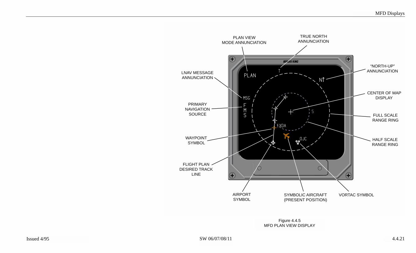
MFD Displays
SW 06/07/08/11Issued 4/95 4.4.21
Figure 4.4.5MFD PLAN VIEW DISPLAY
ı
MSG
PLAN
FMS
IXDA
OJC
5
T
N
PLAN VIEWMODE ANNUNCIATION
TRUE NORTHANNUNCIATION
“NORTH-UP”ANNUNCIATION
CENTER OF MAPDISPLAY
FULL SCALERANGE RING
HALF SCALERANGE RING
FLIGHT PLANDESIRED TRACK
LINE
VORTAC SYMBOLSYMBOLIC AIRCRAFT(PRESENT POSITION)
LNAV MESSAGEANNUNCIATION
PRIMARYNAVIGATION
SOURCE
WAYPOINTSYMBOL
AIRPORTSYMBOL

MFD Displays
SW 06/07/08/11Issued 4/95 4.4.22
Figure 4.4.6TCAS ONLY DISPLAY
ı
TCAS
10TA/RAFLABV
+02
-01
-03
-05
RAINTRUDER
(TCAS II ONLY)
TAINTRUDER
PROXIMATEINTRUDER
OTHERTRAFFIC
DISPLAYMODE
TCASRANGE
NO BEARINGINTRUDERS
TCAS MODESELECTION
(TA/RA - TCAS II ONLY)
ACTUAL/RELATIVEALTITUDE SELECTION
ABOVE/NORM/BELOWALTITUDE SELECTION
TA5.7NM/-06RA0.8NM/+012 NM
RANGERING

MFD Displays
SW 06/07/08/11Issued 4/95 4.4.23
Figure 4.4.7MFD CHECKLIST ROOT INDEX PAGE DEFINITION
ı
TITLE CREATOR/VERSION DATA LINE
✓ EMERGENCY PROCEDURES* NORMAL PROCEDURES➩ ABNORMAL PROCEDURES OTHER PROCEDURES NOTE PAGES CLEAR ALL CHECKED ITEMS
USER CREATEDGENERAL USE LINES
FIXED TEXT LINES (YELLOW)USER CAN NOT CHANGE
TST/REF BUTTON BRINGSUP HELP PAGE
CHECKED OFFINDEX ENTRY
PARTIALLYCHECKED OFFINDEX ENTRY
CURSOR LOCATION
USER/INSTALLER IS RESPONSIBLEFOR THE CHECKLIST CONTENTS
TST/REF-HELP

MFD Displays
SW 06/07/08/11Issued 4/95 4.4.24
Figure 4.4.8MFD CHECKLIST SAMPLE PAGE
ı
✓ 1.
✓ 2.
✓ 3.
➩ 4.
5.
6.
7.
TAXI
BRAKES
FLIGHT INSTRUMENTS
NAV EQUIPMENT
ELECTRICAL POWER
MONITOR
ENGINE INSTRUMENTS
THRUST REVERSERS
ANTI ICE SYSTEMS
CHECK
CHECK
SET
CHECK
CHECK
CHECK AND STOWED
CHECK AS REQD

Operating Instructions
5.1Issued 4/95 SW 06/07/08/11
Consult Aircraft Flight ManualSupplement for specific proce-dures and limitations in opera-tion.
PREFLIGHT PROCEDURES
◗START UP
At engine start, power should notbe applied to the EHI 50 system,low voltage may turn the EFS 50system off momentarily, and tran-sient voltages may induce pre-mature failures. With enginesoperating, turn on avionics mas-ter switches, and turn on NAVsystems to remove the EHSIflags.
When power is initially applied tothe EFS 50 system, various flagsmaybe annunciated on the dis-play, representing systems notyet operational.
◗SELF TEST
Adjust BRT control on theEFS 50 CP 467, and CP 469 forthe desired brightness.
After a short warm-up time, pressand hold the TST/REF button forthree seconds to display theSELF TEST. A SELF TESTPASS or SELF TEST FAIL mes-sage will be annunciated. If thesystem is operating properly theSELF TEST PASS message willbe annunciated. If a malfunctionexists, SELF TEST FAIL will beannunciated and the system
should be serviced. Refer to fig-ure 5.1 and 5.2, Self Test annun-ciation. Additionally, the pilotshould ensure that the compassscale is white, which indicatesthat all three colors are opera-tional in the display unit.
Note: Performing the EFS 50Self Test is not required atanytime. If a failure was tooccur or exist, the small REDSG in a red box would be dis-played. This test is intendedto familiarize the pilot with thevarious flagging methodologyused and a quick check forproper color presentation.
The EADI self test page will auto-matically revert to a normal EADIdisplay.
❏ Software 07 and later will alsocause the EHSI to automaticallyrevert from the selftest page tonormal operation.
◗PUSH BUTTON TEST
Check each push button functionon the EFS 50 control panel.Push button operation should beas described in 2.1 EHSI Opera-tion, 2.2 EADI Operation, 2.3RADAR Operation, and 2.4 MFDOperation.
PRE-TAKEOFFPROCEDURES
After the system test has beencompleted, select the desired Pri-
OPERATING INSTRUCTIONS

Operating Instructions
5.2 Issued 4/95SW 06/07/08/11
mary NAV sensor with the NAVsource select push button. Setthe desired course and heading,and check that the appropriatedisplay is present on the indica-tor. Set the desired NAV frequen-cies for the departure phase ofthe flight. Then press the appro-priate push buttons (HSI, ARC,BEARING #1, BEARING #2,etc.) on the EFS 50 control panelfor the desired display presenta-tion.
IN-FLIGHT OPERATION
Select the desired type of NAVsensor for the primary NAV dis-play by pressing the NAV pushbutton until the desired source isannunciated.
Select NAV system #1 (left) or #2(right) by pressing the 1-2 pushbutton.
Select HSI or ARC display bypressing either the HSI or theARC push button.
Select the display mode (mapand/or weather radar) by sequen-tial presses of the HSI or ARCpush button.
Use HEADING SELECT (SYNCor HDG) or COURSE SELECT(DIR or CRS) knobs to select thedesired heading or course.
On the CP 467 control panel, theheading and course knobs maybe used to 1) rapidly acquire theDIRECT TO course to the station(pull DIR knob), or 2) center the
heading bug under the lubberline (pull SYNC knob).
Use the #1 and #2 BEARINGPOINTER SELECT push buttonsto select the sensor desired bypressing the push button until thedesired source is annunciated.These push buttons are alsoused to display independentDME information without a bear-ing pointer.
◗ADF
After selecting ADF mode andtuning ADF #1 receiver to thedesired NDB, set Bearing pointer#1 to ADF which will be used forprimary navigation. Using CRScontrol, select desired course TOor FROM the NDB. The coursedeviation bar on the EHSI nowprovides left-right guidance in fly-ing the selected course just as itwould in flying a VOR course.This eliminates the mental calcu-lations required while tracking anNDB course in the conventionalmanner. NDB station passage isindicated by the TO-FROM indi-cator and Bearing pointer rever-sal. The ADF may becomeinvalid during station passage, aRED X will be displayed in placeof the deviation scale and D-Bar.
Note: ADF D-Bar presentationmay not be available if theADF does not provide a suit-able flag output.
◗LNAV (RNAV)
After selecting LNAV mode andthe desired waypoint, set Bearing

Operating Instructions
5.3Issued 4/95 SW 06/07/08/11
Pointer #1 to the desired #1bearing source. Using CRSknob, select desired course TOor FROM the waypoint (for theon-side LNAV only). The coursedeviation bar on the EHSI nowprovides guidance in flying theselected course. Waypoint pas-sage is indicated by the TO-FROM indicator and waypointBEARING pointer reversal.
Note: Wind vector and speedinformation is presented if sup-plied by ancillary equipmentand only if the system wasconfigured to display the infor-mation during installation.
Once the external LNAV systemtransmits to the EFS 50 that it isin an enroute mode, the EHSIand system sensitivity is set at5NM left or right of course for full-scale CDI deflection.
Note: Depending on the type ofLNAV installed, the LateralDeviation Scale may be differ-ent and may support only DTK.
◗VNAV
VNAV operation greatly dependson the type of VNAV installed. Itis therefore very important torefer to the Aircraft Flight ManualSupplement and VNAV operationmanual for additional information.
APPROACH PROCEDURES
◗ILS APPROACH
On the CP 467 or CP 469 , selectVOR as the Primary NAV sensor
with the NAV push button. Thentune the appropriate ILS frequen-cy. Note on the EHSI that whenan ILS frequency is selectedLOC replaces the VOR annunci-ation, the glideslope scale is dis-played, and as the glide slopeand localizer scales appear onthe EADI the sky/ ground rasteris reduced in size to provide ahigh-contrast background forthem. Once an ILS frequency isselected, the Bearing pointer andTO-FROM indicator associatedwith that NAV disappears.
When DME Hold is selected onthe DME control panel, DME dis-tance is displayed in white.Groundspeed or Time-To-Stationis replaced with the held VORfrequency followed by an orangeH for HOLD. (DME groundspeedand VOR frequency may not bedisplayed in all installations.)
◗BACK COURSE APPROACH
An option may be selected at thetime of installation and certifica-tion to automatically declutter GSinformation when the aircraftheading is greater than + or - 105degrees from selected ILScourse. EHSI NAV MAP CDIsensing is reversed and “BC” isannunciated below the deviationscale. EADI CDI sensing isreversed and “BC” is displayed tothe left of the center diamond.Not all installations will declutterthe glideslope scale. This is adisplay configuration optionselected at the time of installa-tion.

Operating Instructions
5.4 Issued 4/95SW 06/07/08/11
◗ADF APPROACH
After selecting ADF mode andtuning ADF #1 receiver to thedesired NDB, set Bearing pointer#1 to ADF which will be used forprimary navigation. Using CRScontrol, select desired course TOor FROM the NDB. The coursedeviation bar on the EHSI nowprovides left-right guidance in fly-ing the selected course as itwould in flying a VOR course.This eliminates the mental calcu-lations required while tracking anNDB course in the conventionalmanner. NDB station passage isindicated by the TO-FROM indi-cator and Bearing pointer rever-sal. The ADF may becomeinvalid during station passage, aRED X will be displayed in placeof the deviation scale and D-Bar.
Note: ADF D-Bar presentationmay not be available if theADF does not provide a suit-able flag output.
◗LNAV (RNAV) APPROACH
After selecting LNAV mode andthe desired waypoint, set BearingPointer #1 to the desired #1bearing sensor. If the installedLNAV supports selected coursefrom the EFS 50, use the CRSknob to select desired course TOor FROM the waypoint. Thecourse deviation bar on the EHSInow provides guidance in flyingthe selected course. Waypointpassage is indicated by the TO-FROM indicator and waypointBearing pointer reversal.
Once the external LNAV systemtransmits to the EFS 50 that it isin an approach mode, the cyancolors turn green on the EHSIand system sensitivity increasesto 1.25 NM left or right for full-scale CDI deflection. Cross-sideannunciation remains yellow, butthe increased sensitivity is imple-mented if the cross-side LNAV isin Approach Approved mode.
Note: Depending on the type ofLNAV installed, the LateralDeviation Scale may be differ-ent and may only support DTK.
◗VOR APPROACH
After selecting NAV mode andtuning the VOR receiver to thedesired frequency, set BearingPointer #1 to VOR #1. UsingCRS control, select desiredcourse TO or FROM the VORstation. The course deviation baron the EHSI now provides guid-ance in flying the selectedcourse. VOR passage is indicat-ed by the TO-FROM indicatorand Bearing pointer reversal.
◗DECISION HEIGHTSELECTION
Pull the DH set knob on theCP 467 to activate the DH setdisplay on the EADI. Adjust theDH set knob to select the desireddecision height for the particularapproach. Push the DH set knobin, the select DH will be declut-tered until the radar altimeterbecomes valid at or below 2500feet.

Operating Instructions
5.5Issued 4/95 SW 06/07/08/11
LIMITATIONS
For information on EFS 50 sys-tem operating limitations pleaserefer to the approved Flight Man-ual Supplement for the particularaircraft in question, if one is pro-vided.
EMERGENCYPROCEDURES
For information on EFS 50 sys-tem emergency proceduresplease refer to the approvedFlight Manual Supplement for theparticular aircraft in question, ifone is provided.

Operating Instructions
5.6 Issued 4/95SW 06/07/08/11
*This page intentionally left blank.

Operating Instructions
SW 06/07/08/11Issued 4/95 5.7
Figure 5.1EHSI SELF TEST
1
TST
1
CRS 360
33
30W
24
21 15
12E
6
3
VOR 2NMADF 1
HDG
---
CHECK CONFIG
SELF TEST PASS
N
SRCP
DUSG
SG

Operating Instructions
SW 06/07/08/11Issued 4/95 5.8
Figure 5.2EADI SELF TEST
1
360
CHECK CONFIG
SELF TEST PASS
CRS
RA---
360HDG
FD
TST
1
HDG
ATTITUDE FAIL
CP DU
SG SG
OFFDH
HDG
ATT

Fault Annunciations
6.1Issued 4/95 SW 06/07/08/11
GENERAL
EXTERNAL SYSTEM FAILURES
◗HEADING
Once a heading failure is detect-ed, the EHSI lubber line andcourse pointer head and tail areremoved. The lubber line isreplaced by a RED box with aRED HDG inside it. The coursedeviation scale is frozen horizon-tally to perform the function of aconventional CDI. Selectedcourse reference is provided bythe alphanumeric CRS readout inthe upper left corner. If headingwas configured for display onEADI horizon line, a RED boxwith a RED HDG inside it will bedisplayed upper left of center.
During a heading failure the auto-matic Back Course function nor-mally performed by the EFS 50
FAULT ANNUNCIATIONS
system is inhibited. Refer to Fig-ure 6.2 and 6.3.
◗ATTITUDE
Once an Attitude failure is detect-ed, the pitch scale, roll scale, skypointer, horizon line, headingtape, blue sky and brown groundare removed from the display. ARED box with a red “ATTITUDEFAIL” inside it is displayed on ablack background in the uppercenter of the display.
◗FLIGHT DIRECTOR
Once a Flight Director failure isdetected a RED box with a red“FD” inside it will be displayed onthe upper right side of the EADI.Refer to Figure 6.3, EADI Faults.
EFS 50 SYSTEM FAILURES
◗DU—DISPLAY UNIT LOSSOF COOLING
A yellow DU enclosed in a yellowbox is annunciated at the bottomleft center of the EHSI or bottomleft of the EADI when insufficientairflow is detected in the DisplayUnit. Once annunciated, thefaulty Display Unit will continue tooperate for at least 30 minutes ifthe rated ambient temperature isnot exceeded. To extend the
operating time, reduce displayinformation and brightness to aminimum. Refer to Figure 6.1and 6.3.
◗SG—SYMBOL GENERATORLOSS OF COOLING
A yellow SG enclosed by a yel-low box is annunciated at thebottom right center of the EHSIand bottom left of the EADI ifinsufficient airflow is detected in

Fault Annunciations
6.2 Issued 4/95SW 06/07/08/11
the Symbol Generator. Onceannunciated, the Symbol Gener-ator will continue to operate for atleast 30 minutes if the ratedambient temperature is notexceeded. To extend the operat-ing time, reduce display informa-tion and brightness to a mini-mum. Refer to Figure 6.1 and6.3.
◗CP—CONTROL PANEL(CP 467 OR CP 469/A)
A RED CP enclosed by a REDbox is annunciated left center ofthe EHSI and lower left of theEADI if a control panel switchbecomes stuck for greater than10 seconds. If a switch fails thedisplay should maintain all cur-rently selected conditions. If theswitch should become functionalthe fault annunciation will beremoved and normal operationwill be restored. Refer to Figure6.1 and 6.3.
There are two possible MFD con-trol panel faults that can be dis-played on the MFD. One fault isthe normal red CP fault causedby a mode line failure. The sec-ond fault is a red CCP faultcaused by a failure in the check-list control panel processing. Thefaults to be detected by the CP469A to cause this annunciatorinclude the following:
1.CPU test failure2.ROM test failure3.RAM test failure4.Stuck joystick or control panel
key
5. Invalid data in checklist/notesEPROM (checksum failure). Thisfault condition applies only if theEPROM chip is NOT completelyerased. That is, if the checksumtest on EPROM chip data failsbecause the chip is erased, aCCP fault should NOT be raised.This is because the CP469A willcome from the factory with theEPROM chips erased, and it isundesirable for the product toshow a fault straight out of thebox. Only if at least one of thebits in the EPROM are pro-grammed, and the EPROMchecksum test fails will a CCPfault be generated.
◗HEADING SELECT “BUG”
A RED X will be drawn throughthe heading bug if there is aheading select knob failure onthe EFS 50 control panel. Referto Figure 6.2.
◗COURSE SELECT
A RED X will be drawn throughthe course pointer head and tail ifthere is a course select knob fail-ure on the EFS 50 control panel.Refer to Figure 6.2.
◗RCP—RADAR CONTROLPANEL (if equipped)
A RED RCP enclosed by a REDbox is annunciated at the lowerleft center of the EHSI display if aradar control panel failure isdetected. Refer to Figure 6.1.

Fault Annunciations
6.3Issued 4/95 SW 06/07/08/11
◗SG—SYMBOL GENERATOR
A RED SG enclosed by a REDbox is annunciated at the upperleft center of the EHSI or lowerleft of the EADI if certain moni-tored functions are detectedinvalid. If the RED SG annuncia-tion is encountered extreme cau-tion should be used to validateany data used on the display fornavigation. Even after validationand revalidation the data shouldonly be used as supplementaryinformation.
A large RED “SG” appearing ona black back display annunciatesa Symbol Generator failure whichwould result in processed datathat is unusable for navigation.Refer to Figure 6.1 and 6.3.
RAW DATA DEVIATIONANNUNCIATIONS
Pointer/Scale malfunctions areannunciated by removal of theassociated pointer/scale andplacing a RED X drawn in theirplace. A flag presented on thevertical deviation scale will resultin the deviation pointer beingremoved. On the EHSI, thepointer/scale annunciationsinclude L/R deviation, GS or VNand fore/aft in Doppler and hom-ing mode. On the EADI, thescale annunciations include L/Rdeviation and GS or VN. Referto figure 6.1 for display presenta-tions showing these annuncia-tions.
◗BEARING POINTERANNUNCIATIONS
Bearing pointer source failure orinvalid data reception (No Com-puted Data, NCD) causes a REDX to be drawn through thesource annunciator. The bearingpointer or NAVAID symbol is alsoremoved.
◗ALPHANUMERIC READOUTANNUNCIATIONS
Failures affecting alphanumericreadouts are annunciated by aRED X drawn through the read-out. On the EHSI (figure 6.1), thealphanumeric readouts includeNAV bearing pointer source andcourse (CRS) or desired track(DTK).
Failures affecting distance infor-mation are annunciated by REDdashes in the data field. Whenthe Distance Source is opera-tional but not providing valid dis-tance data (no lock on or NCD)dashes the color of the sensorwill be placed in the data field.Speed (KT) and time (MN)annunciation will be removed ifvalid distance, speed and time-to-station information is not pro-vided by the primary NAV sensorsystem.
Failures affecting radio altimeterinformation are annunciated byRED dashes in the data field onthe EADI. When the radioaltimeter source is operationalbut not providing valid data (nolock on or NCD) white dashes

Fault Annunciations
6.4 Issued 4/95SW 06/07/08/11
will be placed in the data field.Refer to Figure 6.3.
◗CHECK CONFIG
A yellow “CHECK CONFIG”message will display in the upperright corner of the EHSI andEADI whenever the system con-figuration memory in the symbolgenerator and aircraft installationrack do not match.
Test routines resident in the sym-bol generator select the best pos-sible system configuration to use,however, the selected configura-tion may not be the intended one.Once the CHECK CONFIG mes-sage is noted, extreme cautionshould be exercised when usingany information. It is also mostimportant that the aircraft betaken to an authorized dealer forrepair as soon possible.
WEATHER RADARANNUNCIATIONS
When a weather radar failureoccurs while operating in the WXmode, a white alphanumericannunciation appears below theWeather Mode annunciation.
The annunciations capable ofbeing displayed when interfacedwith an RDS 81, 82/VP, 84/VPand 86/VP are listed below inorder of priority.
◗WX FLT
Advises a mismatch of mode, tilt,gain or range information
between the EFIS and radar RThas existed for more than 30 sec-onds.◗WX OFF
This annunciation (“OFF” beforeSW 08) is displayed when theradar is off.
◗BUSY VP
Displayed when the radar is inthe continuous VP mode.
◗STB LMT
Displayed when the combinationof tilt, roll, roll trim and pitchexceeds +/- 30 degrees.
◗429 FLT
Displayed when 429 control datais missing or incorrect at theradar RT.
◗ANT FLT
Displayed when the measuredantenna tilt does not match therequested tilt angle.
◗TX FLT
Displayed when a fault is detect-ed in the radar transmitter.
◗RANGE
Displayed when the pilot hasselected the 1000 mile range onthe EFIS. The radar is unable tooperate at this range and isplaced in standby.

Fault Annunciations
6.5Issued 4/95 SW 06/07/08/11
❏ Installation with an RDS 81,RDS 82 or RDS 82VP with soft-ware 07 or later, “RANGE” willannunciate when the 5 NM, 320NM or 1000 NM range is selected.❏ Installation with software 06“WX FLT” (weather fault) willannunciate when the 5 NM or320 NM range is selected.These annunciations alert thepilot of a range mismatchbecause the RDS 81, RDS 82and RDS 82VP do not supportthese radar ranges.
◗STB OFF
Displayed when stab off hasbeen selected or when the stabi-lization reference is not presentat the radar.
◗WAIT
Displayed when in VP mode andone of the TRACK buttons ispressed, indicating the radar willperform the desired slicing func-tion as soon as the antennareturns to the last selected profil-ing azimuth angle.
◗TCAS FAULT MESSAGES
The TCAS ONLY display on anMFD will be replaced with up tosix yellow fault messages. Dur-ing this tie the annunciated TCASstatus will be either “TCAS FAIL”or “NO TCAS” as appropriate.Except for the status annuncia-tion and fault messages, the dis-play will be completely black.
The fault messages are listed inorder of priority with the highest
first. TCAS FAIL messages havepriority over NO TCAS mes-sages, however both can be dis-played simultaneously (up to sixtotal).
Note: The following is a com-plete list of all TCAS II faultsthat the EFIS will display, how-ever some of these are notapplicable to TCAS I and willnot be generated by a TCAS Iprocessor. Refer to the TCASPilot's Guide for more informa-tion.Note: In some installations aremote annunciator may beinstalled to provide full timeTCAS operational status.
Fault Messages forTCAS FAIL:
PROCESSORUPPER ANTENNALOWER ANTENNA
Fault Messages forNO TCAS:
RADIO ALT 1/2RADIO ALT 1RADIO ALT 2XPDR 1/2XPDR 1XPDR 2ATTITUDEHEADINGRA DISPLAY 1/2RA DISPLAY 1RA DISPLAY 2XPDR UPPER ANTXPDR LOWER ANTTCAS TO XPDRCP TO XPDRALT 1/2 TO XPDRALT 1 TO XPDRALT 2 TO XPDR

Fault Annunciations
6.6 Issued 4/95SW 06/07/08/11
*This page intentionally left blank.

Fault Annunciations
SW 06/07/08/11Issued 4/95 6.7
Figure 6.1EHSI FAULT ANNUNCIATION
ı
LOC
1
CRS 360
N33
30W
24
21S
15
12E
6
3
---NM
DU SG
SG
RCP
CP
045°
VOR 2NM16.3ADF1

Fault Annunciations
SW 06/07/08/11Issued 4/95 6.8
Figure 6.2EHSI FAULT ANNUNCIATION
ı
LOC
1
CRS 360
11.511.5
N33
30W
24
21 S15
12E
6
3
ADF 1
HDG ---NM
045°
VOR 2NM16.3
DME1

Fault Annunciations
SW 06/07/08/11Issued 4/95 6.9
Figure 6.3EADI FAULTS
ı
F
S
6
KT
3N T
RA
20
10
20
10
20
10
20LOC
CP DU
SG
DH
10
12555
APRHB
CWS
SR NAV
HDG
VNAVAP
YD
---
200
GS
AN
ATTITUDE FAIL
CHECK CONFIG
TEST
FD
ALTGS
SGDME1

REVERSIONARY Modes
7.1Issued 4/95 SW 06/07/08/11
The EFS 50 provides four differ-ent reversionary modes of opera-tion in the event of a systemcomponent failure; composite,display down and SG 3. Thereversionary modes offered in aparticular aircraft will varydepending on EFIS system con-figuration, installation wiring andcertification. The following sec-tion describes the various rever-sionary modes offered.
All external switches and plac-ards are part of the installationsupplied by the installer. Forinformation pertaining to a partic-ular aircraft installation refer tothe approved Aircraft Flight Man-ual Supplement.
Note: This Pilot’s Guide refersto the left of the aircraft as thePilot’s position. The right sideis considered the copilot’sposition.
REVERSIONARY MODES

REVERSIONARY Modes
7.2 Issued 4/95SW 06/07/08/11
CMPST - COMPOSITE
Refer to Figure 7.1 ,COMPOSITE MODESELECTION.
CMPST (composite) is generallyused to compensate for a failure
of a display unit or the EADI sec-tion of the symbol generator. Asingle switch input to the SG 465instructs the symbol generator tooutput the CMPST display on theEADI and EHSI. See section 4.3for details on the composite dis-play.
Figure 7.1COMPOSITE MODE SELECTION
EADI
EHSI/MFD/EADI
EADI
EHSI
EFS CONTROL PANEL
CMPSTDISP
CMPSTDISP
CMPSTDISP
SYMBOLGENERATOR

REVERSIONARY Modes
7.3Issued 4/95 SW 06/07/08/11
DISPLAY (EADI) DOWN
Refer to Figure 7.2,EADI DOWN MODESELECTION.
DISPLAY (ADI) DOWN modeselection is generally used tocompensate for a failure of theEADI display unit or section ofthe symbol generator. Availablefor use in two, three, four andfive-tube installations. The DIS-PLAY DOWN mode will allow the
pilot or copilot to transfer the nor-mal EADI display to the EHSIbelow the failed EADI and trans-fer the EHSI display to the MFD ifone is installed. A singlemomentary switch input removespower from the failed EADI,transfers the EFIS control panelcontrol to the MFD symbol gener-ator, instructs the EHSI symbolsection to calculate EADI func-tion and the MFD symbol genera-tor to calculate matching EHSIfunctions.
Figure 7.2DISPLAY (EADI) DOWN MODE SELECTION
EHSI
EFS CONTROL PANEL
RDR CONTROL PANEL
28 VDCAIRCRAFT
POWER
OPEN
EFS CONTROL PANEL
EADI
BLANK
EADI
EHSI/MFD/EADI
EADI
EHSI/MFD/EADI
EADI
SYMBOLGENERATOR
#1
SYMBOLGENERATOR
#2 (3)

REVERSIONARY Modes
7.4 Issued 4/95SW 06/07/08/11
SG 3
Refer to Figure 7.3PILOT STBY MODE SELECTION.
SG 3 mode selection is generallyused to compensate for a failedpilot’s or copilot’s symbol genera-tor. The SG 3 mode selectionwill allow the pilot or copilot tosubstitute the MFD symbol gen-erator for his onside symbol gen-erator. A single momentaryswitch input removes the failedonside symbol generator drivefrom the EADI and EHSI and
transfers the MFD display driveto the onside EADI and EHSI.Also, the MFD control panel inputis removed from the MFD symbolgenerator as the EFIS controlpanel output is switched in. TheMFD symbol generator is nowperforming normal onside EADIand EHSI functions (inputs andoutputs). To alert the pilot orcopilot that the SG 3 mode ofoperation has been selected, ayellow “SG 3” will be annunciatedin the lower right corner of theEADI and EHSI.
Figure 7.3PILOT SG 3 SELECTION
STBY
EADI
EHSI/MFD/EADI
EADI
EHSI
EFS CONTROL PANEL
EHSI
EFS CONTROL PANEL
RDR CONTROL PANEL
EADI
EHSI/MFD/EADI
STBY
STBY
VIDE0
VIDE0
VIDE0
SYMBOLGENERATOR
#1
SYMBOLGENERATOR
#3

Glossary
8.1Issued 4/95 SW 06/07/08/11
GLOSSARY
ABBREVIATIONS
ABV AboveADF Automatic Direction FinderADS Air Data SystemADI Attitude Director IndicatorAHRS Attitude Heading Reference SystemAHS Attitude Heading SystemAN AngleANT AntennaARINC Aeronautical Radio INCorporatedATR Air Transport RadioATT Attitude AZ Azimuth BAZ Back AzimuthBC Back CourseBLW BelowBRG BearingBRT BrightCCP` Checklist Control PanelCDI Course Deviation Indicator or Course
Deviation InformationCDU Control Display UnitCONFIG ConfigurationCP Control PanelCRS CourseCRT Cathode Ray TubeD-BAR Deviation BarDEG Degree(s)DEV DeviationDG Directional GyroDIR DirectDME Distance Measuring Equipment DTK Desired TrackDU Display UnitEADI Electronic Attitude Direction IndicatorED Electronic DisplayEFS or EFIS Electronic Flight Instrument SystemEHI Electronic Horizontal Situation IndicatorEHSI Electronic Horizontal Situation IndicatorFHDG Free Directional Gyro (heading)FL Flight Level (Pressure altitude)FLT FaultFMS Flight Management System

Glossary
8.2 Issued 4/95SW 06/07/08/11
FPL Flight PlanFR FromFT Feet GP Glidepath (used with MLS)GPS Global Positioning SystemGS Ground Speed or GlideslopeHDG HeadingHSI Horizontal Situation Indicator ICAO International Civil Aviation Organization ID IdentificationILS Instrument Landing SystemIRU Inertial Reference UnitKTS Knots (nautical miles per hour)LMT LimitLNAV Long-range NAVigationLOR LoranMLS Microwave Landing SystemNAV NavigationNM Nautical MileOBI Omni-Bearing IndicatorOMG OmegaRA Resolution Advisory/Radio AltimeterRCP Radar Control PanelREF Reference RMI Radio Magnetic IndicatorRNAV Area NAVigationSG Symbol GeneratorSN Sensitivity STB Stabilization STBY StandbySW SoftwareSYNC Synchronization TA Traffic AdvisoryTACAN Tactical Air Navigation TCAS Traffic alert and Collision Avoidance SystemTCN TACAN, Tactical Air Navigation TD Traffic DisplayTST TestTTS Time-To-StationTTW Time-to-WaypointTX TransmitterVNAV Vertical NavigationVOR VHF Omni RangeVORTAC VOR and TACAN co-locatedVP Vertical ProfileWX WeatherWXA Weather Alert

Index
9.1Issued 4/95 SW 06/07/08/11
INDEX
A
ADFADF 1 1.6, 1.10, 1.14, 2.1.6-7, 5.2, 5.4ADF 2 1.6, 1.10, 1.14, 2.1.7
ALPHANUMERIC READOUT ANNUNCIATIONS 6.3AN I.1, 1.1, 1.3, 2.1.3-10, 2.2.1, 2.3.1, 2.3.3, 2.3.6, 2.4.1-6, 4.1.1-2, 4-20,
4.2.1-3, 4.2.5-6, 4.2.8-12, 4.3.1-3, 4.4.1-3, 5, 7-8, 11-14, 5.2-4, 6.1,6.4-5, 8.1
ANT FLT 6.4APPROACH PROCEDURES 5.3ARC
ARC NAV MAP 2.1.4ARC SECTORED MODE SELECTION 2.1.3
ATT 1.8, 1.13, 1.16, 4.2.10, 4.2.12, 8.1ATTITUDE 1.6, 1.10, 1.14, 4.1.1, 4.2.1-2, 4.2.6, 4.2.10, 4.2.12, 6.1, 6.5, 8.1AUTO TILT 2.3.6, 4.1.17
B
BACK COURSEBC 1.8, 1.12, 1.16, 4.1.14, 4.2.6, 5.3, 8.1
BEARING#1 BEARING POINTER 4.1.8#2 BEARING POINTER 4.1.8, 5.21-2 PUSH BUTTON 2.4.3, 2.4.6, 4.1.2, 5.2BEARING POINTER 2.1.6-7, 4.1.5-10, 4.1.14-15, 4.1.18-19, 5.2-4, 6.3BEARING POINTER ANNUNCIATIONS 6.3BEARING POINTER SELECT 2.1.6, 5.2
BRT KNOB 2.1.10, 2.2.1BUSY VP 6.4
C
CATEGORY II 4.2.9-11CHECK CONFIG 6.4CHECKLIST
CHECKLIST INTERFACE 4.4.8COMMAND BARS 1.8, 1.13, 1.16, 4.2.2-3, 4.2.10COMPASS CARD 4.1.1, 4.1.3, 4.1.9-10, 4.1.13-15,, 4.1.17, 4.3.2, 4.4.1COMPOSITE 4.2.9-10, 4.3.1-4, 7.1-2COURSE DEVIATION INDICATOR 4.1.14, 4.1.20, 8.1COURSE SELECT
COURSE SELECT KNOB 2.1.10, 2.4.3-4, 4.1.3-4, 4.4.1, 6.2CRS 1.8, 1.13, 1.16-17, 2.4.4, 4.1.2-4, 4.3.1-2, 4.4.1, 4.4.12, 4.4.15, 5.2-4,
6.1, 6.3, 8.1

Index
9.2 Issued 4/95SW 06/07/08/11
CRS KNOB 2.4.4, 4.1.4, 4.4.1, 4.4.15, 5.3-4CP 466A I.1, 1.1, 2.1.1, 2.3.3, 2.3.6CP 466B I.1, 1.2, 2.3.3, 2.3.6CP 468 2.1.1, 2.1.10, 2.4.2CP 469A I.1, 1.1, 2.4.1, 2.4.5-6, 4.4.3, 4.4.8-9, 4.4.11-13, 6.2
D
DETAILED OPERATING CONTROLS 2.1.1, 2.2.1DG 1.8, 1.12, 1.16, 2.1.3, 4.1.1, 8.1DIRECT TO 1.3, 2.1.10, 5.2DISPLAY BRIGHTNESS CONTROL 2.1.10, 2.2.1DISTANCE, GROUNDSPEED AND TIME-TO-STATION 4.1.5DME
DME HOLD 4.1.6-8, 4.3.1, 4.3.3, 5.3DRIFT ANGLE POINTER 4.1.2, 4.1.12DTK 2.4.4, 4.1.3-4, 5.3-4, 6.3, 8.1
E
EMERGENCY PROCEDURES 4.4.9, 5.5EXTERNAL SYSTEM FAILURES 6.1
F
FAULT ANNUNCIATIONS 6.1-6FR 4.1.14, 4.3.1, 4.3.3, 8.2FREE DG 4.1.1FROM 1.5, 2.1.5, 2.2.2, 2.3.6, 2.4.2, 2.4.4-5, 4.1.4-5, 4.1.7-8, 4.1.10,
4.1.12-16, 4.1.18, 4.1.20, 4.2.1-2, 4.2.6, 4.2.8-9, 4.3.1-3, 4.4.1-2,4.4.5, 4.4.8-9, 4.4.11, 4.4.13-14, 5.1-4, 6.1-2, 7.3-4, 8.2
FT 4.1.11, 4.2.6, 4.2.11-12, 8.2FULL TIME LNAV MAP 4.1.18-19
G
GAIN 2.3.4, 2.3.6, 4.1.17, 6.4GLIDESLOPE
GS 1.8, 1.12, 1.16, 4.1.6, 4.1.11-12, 4.2.3, 4.2.8-9, 4.2.11-12, 5.3, 6.3, 8.2GND MAP 2.3.4-6
H
HEADING SELECTHEADING BUG
HDG BUG 4.1.20HEADING SELECT “BUG” 4.1.3, 6.2HEADING SELECT KNOB 2.1.10, 4.1.3, 6.2

Index
9.3Issued 4/95 SW 06/07/08/11
HEADING SYNC 2.1.10HSI 2.1.3, 2.4.2, 2.4.4, 4.1.15, 4.2.7, 4.2.9-10, 4.4.14, 5.2, 8.2
I
ILSILS APPROACH 4.1.4, 5.3
IN-FLIGHT OPERATION 5.2
K
KNS 81 2.4.4
L
LATERAL COURSELATERAL COURSE DEVIATION BAR 4.1.5, 4.3.2LATERAL COURSE DEVIATION SCALE 4.1.4, 4.3.2
LIGHTNINGLIGHTNING DETECTION 4.1.17
LIMITATIONS 5.1, 5LNAV
LNAV MAP 2.1.8-9, 2.4.2, 2.4.4, 4.1.18-19LOC 4.1.14, 4.2.6-7, 4.2.12, 5.3LOR 2.1.6, 4.1.9, 4.1.12, 8.2
M
MAGNETICMAG 4.1.9-10MAG VAR 4.1.9-10
MAP360 MAP DISPLAYS 4.1.13360 NAV MAP 2.1.3MAP 360 COMPASS CARD 4.1.13MAP COURSE DEVIATION INDICATOR 4.1.14NO MAP 4.1.14, 4.1.18
MEMORY 2.1.4, 4.4.9-11, 6.4MFD I.1, 1.1-3, 1.6, 1.8, 1.10, 1.12, 1.14, 1.16, 2.1.1, 2.1.3-4, 2.1.7-8, 2.3.6,
2.4.1-6, 4.1.7, 4.1.16-17, 4.4.1-16, 5.1, 6.2, 6.5, 7.3-4MULTI FUNCTION DISPLAY 1.1, 2.4.1MLS 1.6, 1.11, 1.14, 1.17, 2.1.7, 4.1.4-8, 4.1.10-11, 4.2.6-8, 4.2.10, 4.2.12,
4.3.2-3, 8.2MODE
1-2 2.1.5-6, 2.4.3, 2.4.6, 4.1.2, 4.4.12, 4.4.14, 5.2360-DEGREE MODE 2.1.3
Index
9.4 Issued 4/95SW 06/07/08/11
N
NAV1-2 NAVIGATION SYSTEM SELECT 2.1.6NAV CDI MAP 2.1.3NAV MAP 2.1.3-4, 2.1.7, 2.1.9, 2.4.4, 4.1.4, 4.1.15-16, 4.4.2, 5.3NAV NAVIGATION SENSOR SELECT 2.1.4NAVIGATION SOURCE ANNUNCIATION 4.1.2, 4.3.2
NDB 4.1.10, 5.2, 4
O
OFF 2.2.2, 2.3.4, 2.3.6, 2.4.3-4, 2.4.6, 4.1.10, 4.1.13, 4.1.15-16, 4.1.18-19,4.2.3, 4.2.6, 4.4.2, 4.4.9-10, 4.4.12-14, 5.1, 6.4
OFF-STBY-TST-ON 2.3.4OMG 2.1.6, 4.1.9, 4.1.12, 8.2ON I.1-2, 1.1, 1.3, 1.6, 1.8, 1.10, 1.12, 1.14, 1.16, 2.1.2-8, 2.1.10, 2.2.1,
2.3.3-6, 2.4.1-6, 4.1.2-4, 4.1.6-7, 4.1.9-20, 4.2.2, 4.2.5-13, 4.3.1-3,4.4.1-5, 4.4.7-14, 5.1-5, 6.1-5, 7.1-2
OPERATING INSTRUCTIONS 2.1.2, 2.2.1, 5.1-6,
P
PITCH 4.2.1-4, 4.2.6, 4.2.12, 4.3.1, 6.1, 4PRE-TAKEOFF PROCEDURES 5.1PULL ARL 2.3.6PULL AUTO 2.3.6PULL STAB OFF 2.3.6PUSH BUTTON TEST 5.1
R
RADARRADAR CONTROLS 2.1.4, 2.3.3RDR 1400 4.1.16, 4.4.7
RADIO ALTIMETER 1.3, 2.2.2, 4.2.5-7, 4.2.10, 6.3RANGE
RANGE DOWN 2.1.7, 4.4.14RANGE RING 2.4.4, 4.1.13, 4.1.15-16, 4.4.1-2, 4.4.4RANGE SELECTION 2.1.7, 4.1.15, 4.1.17-18, 4.4.4RANGE UP 2.1.7, 2.4.3, 4.4.14
RAW DATA DEVIATION ANNUNCIATIONS 6.3REF
REF MAP FORMAT 2.1.9REVERSIONARY MODE 4.1.6, 4.2.9, 4.2.12RISING RUNWAY 1.9, 1.13, 1.17, 4.2.5-7, 4.2.10-12RNAV
RNV 4.1.9

Index
9.5Issued 4/95 SW 06/07/08/11
ROLL 1.8, 1.13, 1.16, 4.2.1-4, 4.2.12, 4.3.1, 6.1, 6.4
S
SELECTED COURSE 2.1.5, 2.1.10, 2.4.4, 4.1.3-5, 4.1.11-14, 4.2.6, 4.2.8,4.3.1-2, 4.4.1, 5.2-4, 6.1
SELF TEST 2.1.8, 2.2.2, 5.1SN 8.2SOFTWARE
SOFTWARE 06 1.6, 2.1.8-9, 2.4.2-3, 4.2.3, 4.2.9-10, 6.5SOFTWARE 07 1.10, 2.1.7, 2.4.2, 4.1.6, 5.1, 6.4SOFTWARE 08 1.14, 2.1.6-8, 2.4.1-3, 2.4.5, 4.1.5-7, 4.1.11, 4.2.8, 4.4.3,
4.4.8SOFTWARE 11 1.18, 2.3.6, 4.1.4-5,4.1.11, 4.2.13, 4.3.3, 4.4.20
STAB OFF 2.3.6, 6.4STANDARD EHSI DISPLAYS 4.1.1, 4.1.15START UP 5.1STB LMT 6.4STB OFF 6.4STBY 2.3.4, 4.1.16, 4.4.6, 7.4, 8.2SYMBOL
SG I. 1, 1. 1, 1.3, 1.6, 1.10, 1.14, 1.17 4.2. 12, 5. 1, 6. 1, 6.3, 7. 1-2,7.4, 8. 2
SYMBOL GENERATOR I. 1, 1. 3, 2.1. 4, 4.1. 7, 4.2. 9-10, 4.2.12-13,4.3. 1, 4.4. 9, 6. 1-4, 7. 2-4, 8. 2
SYMBOL GENERATOR LOSS OF COOLING 6. 1SYMBOLIC AIRCRAFT 2.4.2, 2.4.5, 4.1.3-4, 4.1.10, 4.1.16-17, 4.2.2,
4.3.1, 4.4.1-2, 4.4.4SYSTEM CONFIGURATION 1.1-18, 4.1.2, 6.4, 7.1
T
TCASTCAS INTERFACE
TCAS ONLY BUTTON 2.4.2TCAS ONLY SELECTION 4.4.3TCAS DISPLAY FORMAT 4.4.4TCAS TRAFFIC SYMBOLOGY 4.4.4TCAS DISPLAY ANNUNCIATIONS 4.4.5TCAS ONLY DISPLAY 4.4.22TCAS FAULT MESSAGES 6.5
TCN 2.1.6, 4.1.9, 8.2TILT 2.3.6, 4.1.16-17, 6.4TO I.1-2, 1.1, 1.3, 1.5-6, 1.10, 1.14, 2.1.2-10, 2.2.1-2, 2.3.1-6, 2.4.1-6,
4.1.1-20, 4.2.1-3, 4.2.5-10, 4.2.12-13, 4.3.1-3, 4.4.1-15, 5.1-5, 6.1-5,7.1-4
TO-FROM 5.2-4TRUE 2.4.4, 4.1.9-10, 4.1.15, 4.2.10, 4.2.13, 4.4.2

Index
9.6 Issued 4/95SW 06/07/08/11
TST 2.1.8-9, 2.2.2, 2.3.4, 2.4.6, 4.4.3, 4.4.15, 5.1, 8.2TST/REF
SELF TEST 2.1.8, 2.2.2, 5.1TX FLT 6.4
V
VN 4.1.11, 4.2.8, 6.3VNAV 1.7, 1.11, 1.15, 1.17, 4.1.10-11, 4.2.3, 4.2.7-8, 5.3, 8.2VOR
VOR APPROACH 5.4VERTICAL PROFILE
VP 2.3.2-3, 2.3.5-6, 4.4.1-2, 6.4-5, 8.2
W
WAIT 2.3.5, 6.5WEATHER
WEATHER RADAR ANNUNCIATIONS 6.4WX 2.1.8, 2.3.4-5, 4.1.16-17, 6.4-5, 8.2WX FLT 2.1.8, 4.1.17, 6.4-5WXA 2.3.4-5, 4.1.17, 8.2
WIND VECTORWIND VECTOR INFORMATION 4.1.12

EFS 50Pilot’s Guide
5-inch Electronic FlightInstrumentation System
BAlliedSignal General Aviation Avionics400 North Rogers RoadOlathe, Kansas 66062-1212TELEX 669916 KINGRAD FAX 913-791-1302TELEPHONE (913) 768-3000
©1995 AlliedSignal Inc.4/95 006-08485-0000 1K PRINTED IN THE U.S.A.SW 06/07/08/11
AA


