ETSI EG 202 518 V1.3.1 (2010-01) ETSI Guide Speech and multimedia Transmission Quality (STQ); Acoustic Output of Terminal Equipment; Maximum Levels and Test Methodology for Various Applications
Transcript
ETSI EG 202 518 V1.3.1 (2010-01)
ETSI Guide
Speech and multimedia Transmission Quality (STQ);Acoustic Output of Terminal Equipment;Maximum Levels and Test Methodology
650 Route des Lucioles F-06921 Sophia Antipolis Cedex - FRANCE
Tel.: +33 4 92 94 42 00 Fax: +33 4 93 65 47 16
Siret N° 348 623 562 00017 - NAF 742 C
Association à but non lucratif enregistrée à la Sous-Préfecture de Grasse (06) N° 7803/88
Important notice
Individual copies of the present document can be downloaded from: http://www.etsi.org
The present document may be made available in more than one electronic version or in print. In any case of existing or perceived difference in contents between such versions, the reference version is the Portable Document Format (PDF).
In case of dispute, the reference shall be the printing on ETSI printers of the PDF version kept on a specific network drive within ETSI Secretariat.
Users of the present document should be aware that the document may be subject to revision or change of status. Information on the current status of this and other ETSI documents is available at
http://portal.etsi.org/tb/status/status.asp
If you find errors in the present document, please send your comment to one of the following services: http://portal.etsi.org/chaircor/ETSI_support.asp
Copyright Notification
No part may be reproduced except as authorized by written permission. The copyright and the foregoing restriction extend to reproduction in all media.
DECTTM, PLUGTESTSTM, UMTSTM, TIPHONTM, the TIPHON logo and the ETSI logo are Trade Marks of ETSI registered for the benefit of its Members.
3GPPTM is a Trade Mark of ETSI registered for the benefit of its Members and of the 3GPP Organizational Partners. LTE™ is a Trade Mark of ETSI currently being registered
for the benefit of its Members and of the 3GPP Organizational Partners. GSM® and the GSM logo are Trade Marks registered and owned by the GSM Association.
Intellectual Property Rights ................................................................................................................................ 4
5.1 Maximum level for 8-hour daily noise exposure (TWA) ................................................................................... 9
5.2 Maximum level for peak sound pressure (<500 ms) ........................................................................................ 10
5.3 Other noise exposure requirement .................................................................................................................... 10
6 Test Equipment, setups and procedures ................................................................................................. 11
6.1 Test equipment ................................................................................................................................................. 11
6.1.1 Selection of artificial ear ............................................................................................................................. 11
6.2.2.1.1 Analogue terminal test circuit .......................................................................................................... 15
6.2.2.1.2 Analogue terminal test signal .......................................................................................................... 15
6.2.2.2 Wired digital terminal ........................................................................................................................... 16
6.2.2.2.1 Digital terminal test circuit .............................................................................................................. 16
6.2.2.2.2 Digital terminal test signal ............................................................................................................... 17
6.2.2.3 Wireless digital terminal ....................................................................................................................... 18
Annex A: Alternative daily noise exposure measurement .................................................................. 19
A.2 Description of the method ...................................................................................................................... 19
History .............................................................................................................................................................. 25
ETSI
ETSI EG 202 518 V1.3.1 (2010-01)4
Intellectual Property Rights IPRs essential or potentially essential to the present document may have been declared to ETSI. The information pertaining to these essential IPRs, if any, is publicly available for ETSI members and non-members, and can be found in ETSI SR 000 314: "Intellectual Property Rights (IPRs); Essential, or potentially Essential, IPRs notified to ETSI in respect of ETSI standards", which is available from the ETSI Secretariat. Latest updates are available on the ETSI Web server (http://webapp.etsi.org/IPR/home.asp).
Pursuant to the ETSI IPR Policy, no investigation, including IPR searches, has been carried out by ETSI. No guarantee can be given as to the existence of other IPRs not referenced in ETSI SR 000 314 (or the updates on the ETSI Web server) which are, or may be, or may become, essential to the present document.
Foreword This ETSI Guide (EG) has been produced by ETSI Technical Committee Speech and multimedia Transmission Quality (STQ).
1 Scope The main purpose of the present document is to provide guidance for use of terminal equipment using a handset or headset to equipment providers, e.g. operators of contact centres and their suppliers, who seek to ensure that users are not exposed to acoustic pressure levels in excess of the limits set out in Directive 2003/10/EC [i.3].
The present document gives guidance on procedures for measuring acoustic exposure from handset and headset terminal equipment and guidance on the maximum acoustic levels required to protect users' hearing.
The "startle effects" caused by sudden acoustic signals are outside the scope of the present document.
The present document does not deal with loud speaking telephones.
2 References References are either specific (identified by date of publication and/or edition number or version number) or non-specific.
• For a specific reference, subsequent revisions do not apply.
• Non-specific reference may be made only to a complete document or a part thereof and only in the following cases:
- if it is accepted that it will be possible to use all future changes of the referenced document for the purposes of the referring document;
- for informative references.
Referenced documents which are not found to be publicly available in the expected location might be found at http://docbox.etsi.org/Reference.
NOTE: While any hyperlinks included in this clause were valid at the time of publication ETSI cannot guarantee their long term validity.
2.1 Normative references The following referenced documents are indispensable for the application of the present document. For dated references, only the edition cited applies. For non-specific references, the latest edition of the referenced document (including any amendments) applies.
Not applicable.
2.2 Informative references The following referenced documents are not essential to the use of the present document but they assist the user with regard to a particular subject area. For non-specific references, the latest version of the referenced document (including any amendments) applies.
[i.1] IEC 60651: "Sound level meters".
[i.2] ETSI I-ETS 300 677 (1996): "Public Switched Telephone Network (PSTN); Requirements for handset telephony".
[i.3] Directive 2003/10/EC of the European Parliament and of the Council of 6 February 2003 on the minimum health and safety requirements regarding the exposure of workers to the risks arising from physical agents (noise), Official Journal; OJ L42, 15.02.2003, p.38.
[i.4] ITU-T Recommendation P.360: "Efficiency of devices for preventing the occurrence of excessive acoustic pressure by telephone receivers and assessment of daily noise exposure of telephone users".
[i.5] ITU-T Recommendation P.340: "Transmission characteristics and speech quality parameters of hands-free terminals".
[i.6] US Code of Federal Regulations, 29CFR1910.95: "Occupational noise exposure", (2004 Edition).
NOTE: See http://www.gpoaccess.gov/cfr/index.html.
[i.7] ITU-T Recommendation P.58: "Head and torso simulator for telephonometry".
[i.8] ISO 11904-1:2002: "Acoustics - Determination of sound immission from sound sources placed close to the ear - Part 1: Technique using a microphone in a real ear (MIRE technique)".
[i.9] ISO 11904-2:2004: "Acoustics - Determination of sound immission from sound sources placed close to the ear - Part 2: Technique using a manikin (manikin technique)".
[i.10] ITU-T Recommendation P.380: "Electro-acoustic measurements on headsets".
[i.12] IEEE 269-2002: "Standard Methods for Measuring Transmission Performance of Analog and Digital Telephone Sets, Handsets, and Headsets".
[i.13] CENELEC EN 50332-2 (2003): "Sound system equipment: Headphones and earphones associated with portable audio equipment - Maximum sound pressure level measurement methodology and limit considerations - Part 2: Matching of sets with headphones if either or both are offered separately".
[i.14] ETSI I-ETS 300 245-2: "Integrated Services Digital Network (ISDN); Technical characteristics of telephony terminals; Part 2: PCM A-law handset telephony".
[i.15] UL/CSA60950-1:2007: "Information Technology Equipment - Safety - Part 1: General Requirements".
[i.16] IEC 61000-4-5: "Electromagnetic compatibility (EMC) - Part 4-5: Testing and measurement techniques - Surge immunity test".
[i.17] ETSI ES 201 168: "Speech Processing, Transmission and Quality Aspects (STQ); Transmission characteristics of digital Private Branch eXchanges (PBXs) for interconnection to private networks, to the public switched network or to IP gateways".
3.1 Definitions For the purposes of the present document, the following terms and definitions apply:
contact centre user environment: multiple users serviced by ACD hardware and/or ACD software
NOTE: Frequently, calls automatically appear to the agent announced by a zip tone and do not require action by the agent to answer. Supervisors are frequently cordless or wireless connected. Agents may take several dozen calls per day in a typical help-desk installation, up to a few hundred calls per day. Contact Centres frequently have moderate background babble.
home user environment: single or multiple telephone line from public utility, PSTN or increasingly, a mobile phone or DSL service
NOTE: This environment may suffer interferences from other facilities, such as wireless LAN. Typically the background noise of home offices is low.
mobile user environment: user communicates in multiple environments such as in the car, at airports, outdoors, and in an office environment and as such, has a wide distribution of background noises
office user environment: multiple telephone lines from a PBX, IP-PBX, or Centrex service
NOTE: Typically includes several telephones which may be wireless or corded installed at each work station. Value added services, such as voice mail are managed by the PBX. Also offices usually have low background noise.
open-field: where the sound or noise sources are at a distance from a person's ear
NOTE: The sound or noise environment can be a combination of more acoustic fields, i.e. free, partially reflected, diffused and reverberant fields.
startle effect: psychological effect caused by some types of acoustic stimulation that, whilst of relatively low level, may cause disturbance to some users
3.2 Symbols For the purposes of the present document, the following symbols apply:
dB(A) Sound Pressure Level in deciBel with A-Weighting dB(C) Sound Pressure Level in deciBel with C-Weighting dBFS dB Full Scale dBSPL Sound Pressure Level in deciBel LEX,8h time-weighted average of the noise exposure level for a nominal 8-hour working day
NOTE: It covers all noise present at work, including impulsive noise. Unit: dB(A) ref. 20 µPa.
Ppeak maximum value of C-weighted Peak Sound exposure. Unit: dB(C) ref. 20 µPa
3.3 Abbreviations For the purposes of the present document, the following abbreviations apply:
ACD Automatic Call Distribution AGC Automatic Gain Control DRP Drum Reference Point EC European Commission ERP Ear Reference Point HATS Head And Torso Simulator HRTF Head Related Transfer Function MIRE Microphone In Real Ear OSHA Occupational Safety and Health Administration PSTN Public Switched Telephone Network RLR Receive Loudness Rating RWP Recommended Wearing Position
ETSI
ETSI EG 202 518 V1.3.1 (2010-01)8
TWA Time-Weighted-Average
4 Introduction The Directive 2003/10/EC [i.3] requires the member states to comply the new noise exposure limit requirement after February 15, 2006. The required limits are tabulated in table 1.
The information and guidance provided in the present document will be useful for safety authorities and test laboratories.
Table 1: Exposure Limits Set Out in Directive 2003/10/EC [i.3]
These limits are set for the actual noise exposure received by a person in an "open-field" environment. An "open-field" environment is an environment where the sound or noise sources are at a distance from a person's ear. The sound or noise environment can be a combination of more acoustic fields, i.e. free, partially reflected, diffused and reverberant fields.
The noise exposures from handset and headset terminal equipments are different from the "open-field" environment. They are localized at or inside of users' ear. The present document addresses how to relate the exposure limits set in the Directive to handset and headset terminal equipment applications and to advise how to measure and assess the noise exposure from handset and headset terminal equipments.
The noise exposure from handsets and headsets are also different from an "open-field" in the following ways:
• The level is highly dependent on the extent to which the earpiece is sealed to the ear and the position in which it is held.
• The user may be able to adjust the volume to a level he finds satisfactory.
• The user is normally able to reduce the effects of uncomfortable and rapid increases in sound level by moving the handset or the headset earpiece away from the ear. The time needed for such movement is typically very short.
The present document provides recommendations to help to prevent excessive acoustic exposure by the following means:
• Manufacturers of terminal equipment can, through their designs, limit the absolute maximum sound pressure that terminal equipment can generate.
• Manufacturers of terminal equipment can provide a volume control to enable the user to adjust the sound level of the terminal equipment to a level that is comfortable and intelligible. However the user does not need to adjust the volume control at maximum setting most of the time.
• Manufacturers of terminal equipment can provide equipment with earpieces for both ears instead of only one ear as such equipment may significantly attenuate the ambient noise and allow the user to listen at lower sound pressure level. Additionally, due to the bilateral acoustic excitation, the same psychological loudness is perceived by the agent with a significantly lower level in each ear.
Contact centres can control the ambient noise to encourage agents to lower their listening levels.
ETSI
ETSI EG 202 518 V1.3.1 (2010-01)9
5 Acoustical output signals This clause describes the different signals that can cause excessive noise exposure and explains the proposed limits.
Acoustic signals from terminal equipment can be classified into normal and abnormal signals: normal signals include speech, music on hold, call progress tones (e.g. dial tone, busy tone, and ring tone, etc.), function notification tones (e.g. call waiting, battery low, etc.) and other signals that are intended and created to be heard by the user.
Examples of abnormal signals are: unstable acoustic feedback and other oscillation, fax or modem tones, switching clicks, signal drop out in mobile and cordless phones (resulting in strong noise signals) and high amplitude electrical pulses applied to power and network, e.g. lightning surges, etc. The occurrence of the abnormal signals is often random, sudden and unexpected. The levels can be relatively high.
Users react to the abnormal signals by removing the handset or headset from their ears, switching off the connection or similar actions. In general the exposures to such signals are short as the users find these signals unpleasant and remove the signal from their ear as quickly as they can. The likely time duration for the exposure to such signals is estimated to be about two or three seconds at most.
5.1 Maximum level for 8-hour daily noise exposure (TWA) Daily Noise Exposure is a Time-Weighted-Average (TWA) of A-weighted noise exposure. Conventionally it is for a normal 8-hour workday. It applies only to work related environment, e.g. contact centre. The daily noise exposure (TWA) measurement accounts for both normal and abnormal signals. The limit for the daily noise exposure is referenced from the Directive 2003/10/EC [i.3] as stipulated in table 1.
For a constant sound pressure level exposure that lasts 8 hours, the 8-hour TWA will be equal to the sound pressure level. For varying sound pressure, the 8-hour TWA can be calculated with equation (1):
)( ( ) ( )
2
1
2
2,8
2 1 0
1 110log
EX h A
tt dt dB A
tpL
pt t
⎡ ⎤⎢ ⎥=⎢ ⎥−⎣ ⎦
∫ (1)
Where:
• LEX,8h is the TWA of the noise exposure level for an 8-hour workday, dBSPL(A). It covers all noise present at
work, including impulsive noise;
• t1 is the starting time;
• t2 is the ending time. For a nominal 8-hour working day, t2 – t1 = 8 (hours);
• PA(t) is the instantaneous A-weighted sound pressure of the sound signal;
• Po is the reference sound pressure of 20 µPa.
NOTE 1: The U.S. Code of Federal Regulations [i.6] integrates only the sound levels above 80 dB, whereas in Europe, the Directive does not make such limitation.
Reducing the daily noise exposure duration allows an increase in the exposure limit, vis-à-vis, reducing the exposure limit allows an increase in the exposure duration. The trading relation is "3 dB per time-doubling", 3 dB increase/decrease in a constant sound level doubles/halves the acoustic energy of the exposure, as does doubling/halving the duration of the exposure. This relation can be expressed in equation (2):
80
3
8
2EX
TL⎛ ⎞−
⎜ ⎟⎜ ⎟⎝ ⎠
= (Hour) (2)
ETSI
ETSI EG 202 518 V1.3.1 (2010-01)10
Where:
• T is the permissible noise exposure duration (hour);
• LEX is the corresponding maximum noise exposure level, dB(A).
NOTE 2: The US Code of Federal Regulations [i.6] uses "5 dB per time-doubling" exchange rate.
Daily noise exposure (TWA) is intended to be calculated from measurements made on-site. The measurement method is discussed in clause 6.2.1.
5.2 Maximum level for peak sound pressure (<500 ms) The peak sound pressure level defined in Directive 2003/10/EC [i.3] and stipulated in table 1 is an exposure limit to a peak impulse noise signal. It is also defined as an instantaneous noise exposure. The Directive does not specify the duration of a noise signal to be considered as an instantaneous noise. Nevertheless, ITU-T Recommendation P.360 [i.4] states that "Tones or other disturbances which are inherently limited to less than 0,5 seconds duration should be evaluated as short duration impulses".
The user has no control of this impulse noise signal. It is a firm limit that is controlled by the terminal equipment. The Peak Sound Pressure can be measured in a laboratory with appropriate test signals and setup. The measurement method is discussed in clause 6.2.2.
5.3 Other noise exposure requirement Directive 2003/10/EC [i.3] defines maximum daily noise exposure level and peak sound pressure level. There is another maximum acoustic output level traditionally defined by many telecommunication standards, e.g. ITU-T Recommendation P.360 [i.4], I-ETS 300 245-2 [i.14], I-ETS 300 677 [i.2] and UL/CSA60950-1 [i.15], etc. These telecommunication standards consider the Peak Sound Pressure defined in the Directive to be less than 500 ms in duration. For noise signals equal or longer than 500 ms the telecommunication standards characterize them as a "Long Duration Disturbance".
ETSI terminal documents listed in I-ETS 300 245-2 [i.14] and I-ETS 300 677 [i.2] generally specify a 24 dBPa or 118 dBSPL limit at Ear Reference Point (ERP) for the long duration disturbance within the frequency range of the terminals.
ITU-T Recommendation P.360 [i.4] requires a 24 dBPa(A-weighted) or 118 dB (A-weighted) limit for headsets and 31 dBPa (A-weighted) or 125 dB (A-weighted) limit for handset at ERP for the Long Duration Disturbance.
UL/CSA 60950 requires a 118 dB(A-weighted) limit for headsets and 125 dB (A-weighted) limit for handset at ERP for the Long Duration Disturbance within the frequency range of the terminals.
Since the late 1980's, experience has shown that these long duration disturbance limits have provided satisfactory protection against acoustic injury. The present document advises the maximum level for long duration disturbance to be 118 dB(A-weighted) for headsets and 125 dB(A-weighted) for handsets at ERP.
The user has no control of this long duration disturbance signal. It is a firm limit that is controlled by the terminal equipment. The maximum long duration disturbance can be measured in a laboratory with appropriate test setup and signals. The measurement method is discussed in clause 6.2.2.
It is advisable that the terminal requirements worldwide should be harmonized.
ETSI
ETSI EG 202 518 V1.3.1 (2010-01)11
6 Test Equipment, setups and procedures
6.1 Test equipment
6.1.1 Selection of artificial ear
It is essential to select a correct ear simulator for all acoustic safety tests. The aim is to simulate the actual use of the terminals by real persons. ITU-T Recommendation P.57 [i.11], ITU-T Recommendation P.380 [i.10] and IEEE standard 269 [i.12] give advice on the selection of an artificial ear for handset and headset measurements.
ITU-T Recommendation P.380 [i.10] and IEEE standard 269 [i.12] recommend use of types 3.3 and 3.4 artificial ears for handset and headset measurement. Both artificial ears simulate the acoustical and mechanical characteristics of real ears. However, there are differences between the two types.
Type 3.3 artificial ear is recommended for all types of terminals. Type 3.4 artificial ear is recommended for all types of terminals except supra-concha and supra-aural headsets. For intra-concha headsets type 3.4 ear may be used only if the acoustic outlets face the ear canal.
Both types 3.3 and 3.4 artificial ears are likely to provide more seal than on many human subjects for insert headset measurement. This results in an overestimation of low frequency output. Nonetheless, both artificial ear types are still better than the other standardized types of artificial ears for this application.
For handsets measured on type 3.3 or 3.4 artificial ears, besides coupling them to the headphone as a human user would, i.e. 6 N coupling force, one additional measurement should be made using a 18 N coupling force. The maximum result from the two measurements should be taken as the final result of the noise exposure test.
6.1.2 HRTF Filtering
Types 3.3 and 3.4 artificial ears both measure at the DRP. It is necessary to transfer the sound pressure level measured at the DRP to the "open-field" or to ERP before comparing it to the noise exposure limits defined in clause 5.
It is recommended to use a real time filter to carry out the DRP to "open-field" HRTF translation. This is especially important for peak measurements as both magnitude and phase of the measurement are best preserved in order to accurately evaluate the results. A minimum phase filter is used.
The HRTF filter translation could be accomplished mathematically using a software algorithm to process digitally sampled and stored waveforms. It is the responsibility of the test house to ensure such methods accurately emulate the preferred real time filter method.
The filter parameters for transformation from DRP to "open-field" should be based on the DRP to Diffuse Field transfer function supplied by the manufacturer for the artificial ear if available. Alternatively, the DRP to Diffuse Field transfer function specified in ITU-T Recommendation P.58 [i.7] can be used. Transfer functions with resolution of at least 1/12th octave or R40 format should be used if available.
The magnitude of the filter response should approximate the transfer function within a tolerance of ±1 dB.
NOTE: If the test is passed before application of the DRP to Diffuse Field or to ERP transfer functions, then it is not necessary to apply these conversions for the product to comply with the requirements. This is because an overestimation of the peak pressure and the maximum long duration disturbance will be obtained by just using the measured values of sound pressure at the DRP without translating the result to Diffuse Field or ERP.
6.1.3 Weightings
The daily noise exposure limits defined in the Directive are A-weighted. It is therefore necessary to A-weight the daily noise exposure measurements.
The peak sound pressure limits defined in the Directive are C-weighted instantaneous noise pressure. It is therefore necessary to C-weight the peak measurements.
ETSI
ETSI EG 202 518 V1.3.1 (2010-01)12
The long duration disturbance limit is A-weighted, see clause 5.3.
6.2 Measurement methods
6.2.1 Daily noise exposure (TWA) measurement
Daily noise exposure (TWA) applies mainly for workplace, e.g. contact centres. Headsets are most commonly used in contact centres. Most contact centres are equipped with Automatic Call Distribution (ACD) systems that enable the operators to stay on the telephone for most of their working hours, either listening or talking.
Every contact centre's acoustic environment, operators' listening level, telephone call pattern and telephone system, etc. can be different. For instance, the density of the occupancy, the ambient noise level and acoustic treatment of each contact centre, etc.
The same headset used by different persons can result in different sound pressure levels to the users. It depends on the individual ear and head geometries and how the headset is positioned or coupled to the ear. Different coupling between the headset receiver and the ear varies the acoustic load impedance to the headset receiver.
Caller's background, the culture, the language, and the state of emotion, etc. affect the incoming signal level from call to call, soft, loud, higher crest factor, etc. A user adjustable receive volume control allows the user to adjust the listening level to a user preferred comfortable level. It is natural for a user to adjust the headset receive volume to a level that is not so low that he or she can not hear clearly, nor so loud to be uncomfortable. With a receive volume control, each user has the ability to control his or her own daily noise exposure (TWA).
Because of all of the above, the daily noise exposure (TWA) cannot be tested or evaluated in a laboratory, rather, it should be measured in the field and on site with the real acoustic environment around the user and with the real user's receive volume control setting and the actual incoming signals.
There are three known techniques to perform the daily noise exposure (TWA) measurement; the HATS method [i.9] and [i.13], the Microphone In Real Ear (MIRE) method [i.8] and the OSHA method (indirect measurement).
The present document recommends using the HATS technique. It is similar to the techniques defined in ISO 11904-2 [i.9], "Technique Using a Manikin" and EN 50332-2 [i.13]. The benefit of this technique is that it is not intrusive and is easy to perform. It causes minimal interference to the agent's routine work. However the HATS techniques may not be suitable for handsets and headsets that have built-in, user adjustable, receive volume controls, as it is difficult to ensure the volume control for both the agent's handset or headset and the test handset or headset is set identically.
Measurements using Microphone In Real Ear (MIRE) technique as defined in ISO 11904-1 [i.8] is more intrusive. It requires higher operational skill to perform the measurement. Because the in ear microphone, it is difficult to perform long time duration measurements, which is important in most Daily Noise Exposure measurements in contact centres. The MIRE technique may not work well for handsets and headsets that rely, for their acoustic performances, on a seal between receiver and agent's ears.
The Occupational Safety and Health Administration (OSHA) indirect measurement technique integrates the electrical energy into the receiver and calculates the acoustic noise exposure level from the handset and headset. It uses the least test equipment on the test site, and it is the least intrusive technique. However, the technique requires more laboratory preparation for each measurement. This OSHA method can be an alternative to the method provided in the present document for large scale measurements, see Annex A: Alternative daily noise exposure measurement: Alternative daily noise exposure measurement. The OSHA technique may not work well for handsets and headsets with nonlinear Automatic Gain Control (AGC) technology.
Due to different sources of errors, e.g. the coupling between the ear piece and the ear, the interference of the in ear microphone, the difference between the test headset and the agent's headset, the possible AGC interference and etc., the test results from the above three techniques may vary.
6.2.1.1 Measurement procedure
The present document recommends all daily noise exposure (TWA) be conducted on the site with the particular agent in question as shown in figure 1.
ETSI
ETSI EG 202 518 V1.3.1 (2010-01)13
Headset Amplifier (optional)
Inverse-HRTF Filtering and A-Weighting
Manikin
Buffer Amplifier
Measuring Meter
Terminal
Agent
Splitter
Figure 1: Test setup for measuring daily noise exposure (TWA)
A second headset that is "identical" to the agent's headset is required for this method. "Identical" means that the second headset is the same brand, same model and from the same manufacturer as the agent's headset. If configuration options exist, both headsets should be configured in the same manner e.g. headband or ear hook, ear cushion type, ear bud type, tone control, etc. This is required so that the replicated signal passing to the second headset will result in the same nominal acoustic signal being produced by the agent's headset.
As shown in figure 1, a simple splitter should be used to duplicate the signal after the headset amplifier or any user adjustable receive volume control; one signal is applied to the agent's headsets and the other to the second headset via a buffer amplifier. The buffer amplifier should impose minimal loading of the signal to the agent's headset. The buffer amplifier should then have high input impedance compared to the headset worn by the agent. The buffer amplifier should also have a low output impedance to minimize the voltage drop when driving the second headset. The buffer amplifier should have unity gain, it should not reduce the bandwidth of the income signal nor add significant distortion or noise to the system. It is recommend that the buffer amplifier connects only to the receive channel. The transmit channel is open so that neither the agent nor the far end will be disturbed by stray microphone noise of the second headset.
In some cases a telephone turret provides a secondary socket for a second headset. In such cases, it is important to verify that both sockets provides same output level and the receive volume control on the turret (if any) controls both headsets simultaneously and equally. It has to be sure that there is no additional user adjustable receive volume control between the turret and the agent's headset. It is equally important that the second headset does not alter the noise level from the agent's headset. It is recommend to disable or mute the transmit channel of the second headset.
The agent's headset should be the one normally used by the agent. The second headset should be fitted on the HATS. The acoustic coupling between the second headset and the HATS's ear should be similar to the manner which the agent couples the headset to his or her head and ear. This similarity of acoustic coupling between the headsets and ears is critical to the TWA measurement. It is recommended that the position and coupling between the headset and ears should be monitored periodically during the course of the measurement.
As shown in figure 1, the output from the HATS should be fed to the measurement meter via the Inverse-HRTF and A-weighting filters described in clauses 6.1.2 and 6.1.3. The output signal from the filters is the A-weighted equivalent diffuse field sound pressure level. The measuring meter can be any real time frequency analyzer, sound pressure level meter or simply a noise dose meter that is capable of performing TWA measurements.
It is known that even with a same brand, same model and from a same manufacturer a second headset can still have a different Receive Loudness Rating (RLR) level as the agent's headset. It is necessary to calibrate the second headset before the TWA measurement, the calibration number obtained from clause 6.2.1.2 is added to the final TWA measurement result.
ETSI
ETSI EG 202 518 V1.3.1 (2010-01)14
It is recommended to measure the TWA for the whole working day (mostly 8 hours). However, in some situations, due to the time and cost constraints, the whole working day measurement may not be possible. In such situation, it is important that for each measurement of an agent, the shortened duration is long enough to cover a representative sample of the whole working day activity. A minimum of 2 hours is recommended. Assuming that the shorter duration is representative, it can then be extrapolated to give the noise exposure value for that individual for a whole working day or a particular shift pattern. It is also important to account for different shifts and breaks for the Contact Centre agents.
It is useful to also measure the background unobstructed noise level separately during the TWA measurement. It helps to understand the relation between the background noise level and the agent's listening level.
This test method does not apply to handsets and headsets whose receive volume control are on the handset and headset capsules.
For running a large scale monitoring campaign an alternative equivalent method can be used as the one presented in annex A.
6.2.1.2 Second headset calibration procedure
It is recommended to calibrate the headset alone without connecting to the telephone:
1) Couple the agent's headset on HATS as described in clause 6.2.1.1.
2) Headset with adjustable receive levels are adjusted to the maximum setting.
3) Replace a sound level meter for the measuring meter show in figure 1.
4) Apply a band limited (match the frequency range of the device under test, e.g. narrowband or wideband, etc.) pseudorandom noise for analogue headset and square wave signal for digital headset, directly to the headset receive. Adjust the signal level until the sound level meter reads 90 dB (A-weighted). Record the input signal level in dBV.
5) Repeat step 1) to 4) above for the second headset.
6) Subtract the drive level recorded for the second headset from the drive level recorded for the agent's headset. The difference is the calibration level.
6.2.2 Peak sound pressure exposure and long duration disturbance measurements
Although the permissible peak sound pressure and the long duration disturbance exposure limit levels do not vary, the appropriate test method may vary depending on the type of terminals. For instance, the possible abnormal high level acoustic noise source for a conventional corded analogue terminal can be different from a wireless cell phone terminal. The type of terminals are considered and outlined in table 2.
Table 2: Type of telecommunication terminals
Network Terminating Point
(NTP) to Base
Base to Handset/Headset
Headset/Handset Measurement Method
Wired Analogue
Corded/Cordless
Handset/Headset Clause 6.2.2.1
Wired Digital (ISDN, VoIP, etc.)
Corded/Cordless Handset/Headset Clause 6.2.2.2
Wireless Digital (Mobile Phone,
VoIP, etc.)
Corded Handset/Headset Clause 6.2.2.3
ETSI
ETSI EG 202 518 V1.3.1 (2010-01)15
6.2.2.1 Wired analogue terminal
6.2.2.1.1 Analogue terminal test circuit
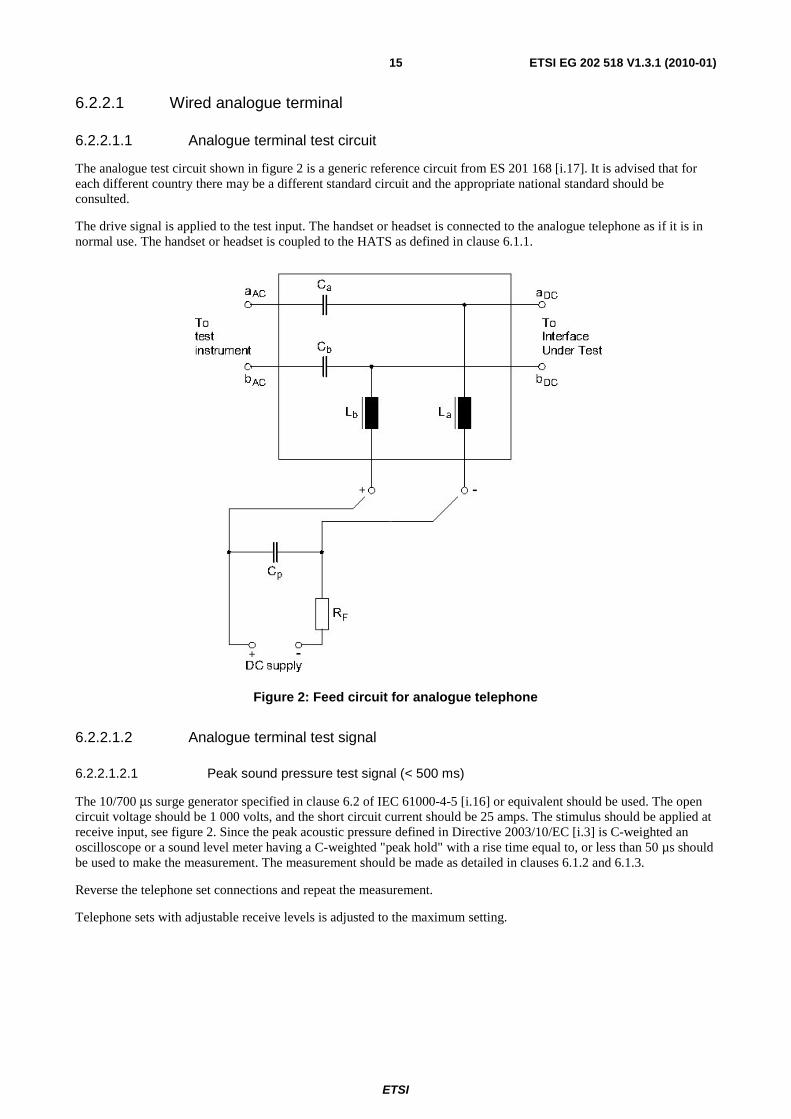
The analogue test circuit shown in figure 2 is a generic reference circuit from ES 201 168 [i.17]. It is advised that for each different country there may be a different standard circuit and the appropriate national standard should be consulted.
The drive signal is applied to the test input. The handset or headset is connected to the analogue telephone as if it is in normal use. The handset or headset is coupled to the HATS as defined in clause 6.1.1.
Figure 2: Feed circuit for analogue telephone
6.2.2.1.2 Analogue terminal test signal
6.2.2.1.2.1 Peak sound pressure test signal (< 500 ms)
The 10/700 μs surge generator specified in clause 6.2 of IEC 61000-4-5 [i.16] or equivalent should be used. The open circuit voltage should be 1 000 volts, and the short circuit current should be 25 amps. The stimulus should be applied at receive input, see figure 2. Since the peak acoustic pressure defined in Directive 2003/10/EC [i.3] is C-weighted an oscilloscope or a sound level meter having a C-weighted "peak hold" with a rise time equal to, or less than 50 µs should be used to make the measurement. The measurement should be made as detailed in clauses 6.1.2 and 6.1.3.
Reverse the telephone set connections and repeat the measurement.
Telephone sets with adjustable receive levels is adjusted to the maximum setting.
ETSI
ETSI EG 202 518 V1.3.1 (2010-01)16
6.2.2.1.2.2 Long duration (≥ 500 ms)
Apply an analogue square wave sweep with the step size of 1/12 octave, at -15 dBV using a generator whose source impedance matches the nominal impedance of the device under test, to the receive input throughout the terminal bandwidth, for instance, for narrowband systems, the switching rate should range from 50 Hz to 8 kHz (i.e. 25 Hz to 4 kHz square wave); for wide-band systems, the switching rate should range from 50 Hz to 16 kHz (i.e. 25 Hz to 8 kHz square wave). The sweep time should be selected so that it provides consistent results with no underestimation.
The detector is set to rms fast, which is a 250 ms effective averaging time (equivalent to a 125 ms time constant). The detector should also be set so that it reads the total A-weighted output sound pressure level across the terminal bandwidth, including the fundamental and all the harmonics for each 1/12 octave band inputs and to hold the maximum level achieved during the entire sweep.
1) Increase the signal level in 5 dB steps until the input level reaches +15 dBV.
2) Adjust the input level in 1 dB steps up and down around the input that yields the highest output until the absolute maximum acoustic output is found.
3) Verify the device is still functioning normally.
NOTE: The test may heat up the device under test, therefore care should be taken to allow the device to cool down when needed.
Telephone sets with adjustable receive levels should be adjusted to the maximum setting.
Telephone sets with adjustable receive levels should be adjusted to the maximum setting. The input level and switching frequency that yields the maximum output is considered to be the "worst case input". At this level and switching frequency the maximum output level is produced.
6.2.2.2 Wired digital terminal
6.2.2.2.1 Digital terminal test circuit
The test equipment consists of an instrument that produces the test signal, a HATS that supports the device being investigated, a minimum phase, parametric filter (or equivalent) that translates DRP to ERP and a measurement meter that records the test results. Figure 3 is a functional block diagram of the test setup.
Signal Generator
Audio Gateway Common
air interface
HATS
D.U.T
Measurement meter
DRP-to- ERP Filter
Figure 3: Digital test diagram
ETSI
ETSI EG 202 518 V1.3.1 (2010-01)17
6.2.2.2.2 Digital terminal test signal
6.2.2.2.2.1 Short duration (< 500 ms)
First, apply a tone burst using the "worst case input" signal producing the maximum output level from clause 6.2.2.2.2.2 with three cycles ON and 500 ms OFF as shown below (a) (if the signal duration is longer than 500 ms, the number of cycles has to be reduced but there is at least one full cycle), to the receive input for at least 10 seconds.
Next, repeat the "first step" with the tone burst with 500 ms ON and 500 ms OFF as shown below (b). The integer number of cycles is chosen so that the maximum duration of 500 ms is achieved as close as possible.
OFF 500 ms
ON Three Cycles
ON Three Cycles
(a)
ON 500 ms
OFF 500 ms
ON 500 ms
(b)
Figure 4: Short duration acoustic pressure test signal
6.2.2.2.2.2 Long duration (≥ 500 ms)
Apply a digital square wave with the step of 1/12 octave at -15 dBFS (full scale) digital code to the receive input throughout the terminal bandwidth, and switch between the maximum positive and the maximum negative values, for the codec used by the device under test. If the values for the used codec are unknown, then the values defined in ITU-T Recommendation G.711 [i.18] (see table 3) should be used. The sweep time should be selected so that it provides consistent results with no underestimation, for instance, for narrow-band system, the switching rate should range from 50 Hz to 8 kHz (i.e. 25 Hz to 4 kHz square wave); for wideband system, the switching rate should range from 50 Hz to 16 kHz (i.e. 25 Hz to 8 kHz square wave).
The detector is set to rms fast, which is a 250 ms effective averaging time, equivalent to a 125 ms time constant (care should be taken so that the signal duration is sufficient to get a stable reading at the output of the test instrument with the detector time chosen). The detector should also be set so that it reads the total A-weighted output sound pressure level across the terminal bandwidth, including the fundamental and all the harmonics for each 1/12 octave band inputs and hold the maximum level achieved during the entire sweep.
1) Increase the signal level in 3 dB steps until the input reaches 0 dBFS, see table 3 for example.
ETSI
ETSI EG 202 518 V1.3.1 (2010-01)18
2) Adjust the input level in 1 dB steps up and down around the input level that yields the highest output until the absolute maximum acoustic output is fund.
3) Verify the device is still functioning normally.
NOTE: The test may heat up the device under test, therefore care should be taken to allow the device to cool down.
The input level and switching frequency that yields the maximum output is considered to be the "worst case input". At this level and switching frequency the maximum output level is produced.
Telephone sets with adjustable receive levels should be adjusted to the maximum setting.
Table 3: PCM codes for zero (quiet code) and full scale
Level Mu-Law A-Law
Sign Bit Chord Bit Step Bits Sign Bit Chord Bits Step Bits + Full Scale 1 000 0000 1 010 1010
+ Zero 1 111 1111 1 101 0101 - Zero 0 111 1111 0 101 0101
- Full Scale 0 000 0000 0 010 1010
6.2.2.3 Wireless digital terminal
The setup of the measurement is to be taken from the relevant standard describing the measurement of the speech performance parameter for the type of the phone to be measured.
The test signals described in clause 6.2.2.2.2 are used. The measurement should be made as detailed in clauses 6.1.2 and 6.1.3.
ETSI
ETSI EG 202 518 V1.3.1 (2010-01)19
Annex A: Alternative daily noise exposure measurement
A.1 Introduction The HATS method specified in the present document needs a very careful execution both in respect of the selection of the second headset to be worn on the HATS, which should be in principle identical to the one used by the agent and the positioning of the headsets on the agent and the HATS, which should be similar. This similar positioning is generally easily assured in limited measurement campaigns, carried out by skilled test operators, but quickly gets more difficult if many measurements are to be carried out in the field by a large number of less skilled test operators, not to mention the need of large quantity of HATS.
Large scale monitoring campaigns may be addressed to thousands of contact centre agents, scattered in different towns and following many different time shift patterns. As a consequence they should be run by complex territorial organizations, normally resorting to the existing field operation personnel. In order to complete a monitoring campaign within acceptable time limits many testing facilities may need to be operated in parallel, each able to monitor many operators at the same time.
Based on these considerations, the HATS based method is not applicable to wide scale monitoring campaigns and the alternative equivalent method described in the following has proven to be more suited to meet the above mentioned constraints.
A.2 Description of the method The method for running large scale monitoring of the daily noise exposure of contact centre agents is based on the following principles:
1) Electric monitoring of the signal at the input of the headset (i.e. after all volume controls).
2) Acoustic monitoring of the background noise in the working environment.
3) Correlation of the measured electric signal with the acoustic pressure at the eardrum by means of a statistically validated model of the headset response, as characterized on the HATS.
4) Calculation of the equivalent sound pressure level of the received speech in the Diffused Field, according to ISO 11904 [i.8] and [i.9].
5) Power summation of the equivalent speech pressure spectrum in the Diffused Field and the ambient noise at the working environment, as measured by the environmental microphone of the test system.
ETSI
ETSI EG 202 518 V1.3.1 (2010-01)20
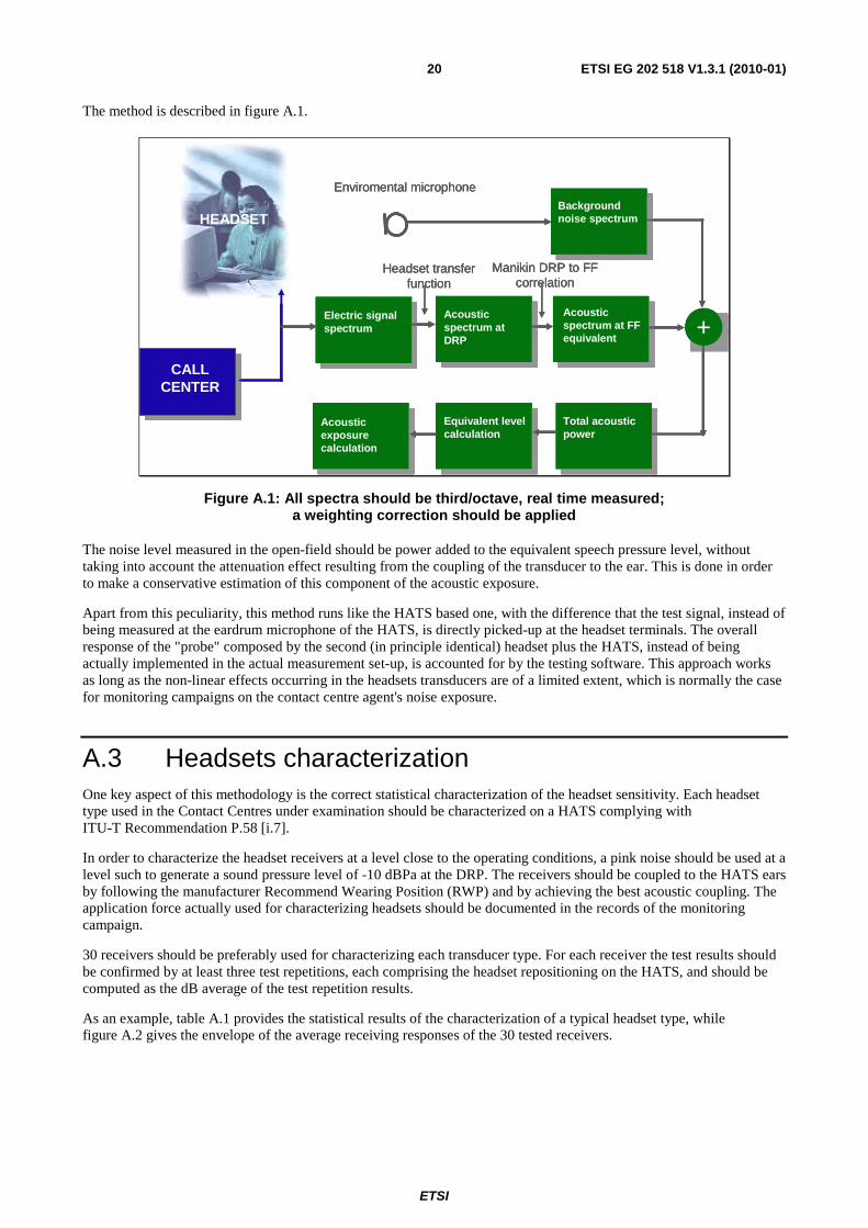
The method is described in figure A.1.
Enviromental microphoneBackground noise spectrum
Electric signalspectrum
CALL CENTER
Acousticspectrum at DRP
Acousticspectrum at FF equivalent +
Total acousticpower
Equivalent levelcalculation
Acousticexposurecalculation
Headset transfer function
Manikin DRP to FF correlation
HEADSET
Enviromental microphoneBackground noise spectrum
Electric signalspectrum
CALL CENTER
Acousticspectrum at DRP
Acousticspectrum at FF equivalent +
Total acousticpower
Equivalent levelcalculation
Acousticexposurecalculation
Headset transfer function
Manikin DRP to FF correlation
Enviromental microphoneBackground noise spectrum
Electric signalspectrum
CALL CENTER
Acousticspectrum at DRP
Acousticspectrum at FF equivalent +
Total acousticpower
Equivalent levelcalculation
Acousticexposurecalculation
Headset transfer function
Manikin DRP to FF correlation
HEADSET
Figure A.1: All spectra should be third/octave, real time measured; a weighting correction should be applied
The noise level measured in the open-field should be power added to the equivalent speech pressure level, without taking into account the attenuation effect resulting from the coupling of the transducer to the ear. This is done in order to make a conservative estimation of this component of the acoustic exposure.
Apart from this peculiarity, this method runs like the HATS based one, with the difference that the test signal, instead of being measured at the eardrum microphone of the HATS, is directly picked-up at the headset terminals. The overall response of the "probe" composed by the second (in principle identical) headset plus the HATS, instead of being actually implemented in the actual measurement set-up, is accounted for by the testing software. This approach works as long as the non-linear effects occurring in the headsets transducers are of a limited extent, which is normally the case for monitoring campaigns on the contact centre agent's noise exposure.
A.3 Headsets characterization One key aspect of this methodology is the correct statistical characterization of the headset sensitivity. Each headset type used in the Contact Centres under examination should be characterized on a HATS complying with ITU-T Recommendation P.58 [i.7].
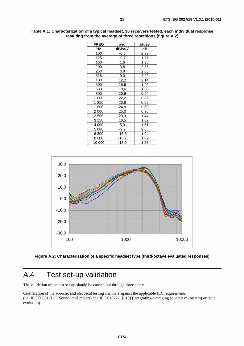
In order to characterize the headset receivers at a level close to the operating conditions, a pink noise should be used at a level such to generate a sound pressure level of -10 dBPa at the DRP. The receivers should be coupled to the HATS ears by following the manufacturer Recommend Wearing Position (RWP) and by achieving the best acoustic coupling. The application force actually used for characterizing headsets should be documented in the records of the monitoring campaign.
30 receivers should be preferably used for characterizing each transducer type. For each receiver the test results should be confirmed by at least three test repetitions, each comprising the headset repositioning on the HATS, and should be computed as the dB average of the test repetition results.
As an example, table A.1 provides the statistical results of the characterization of a typical headset type, while figure A.2 gives the envelope of the average receiving responses of the 30 tested receivers.
ETSI
ETSI EG 202 518 V1.3.1 (2010-01)21
Table A.1: Characterization of a typical headset, 30 receivers tested, each individual response resulting from the average of three repetitions (figure A.2)
Figure A.2: Characterization of a specific headset type (third-octave evaluated responses)
A.4 Test set-up validation The validation of the test set-up should be carried out through three steps:
Certification of the acoustic and electrical testing channels against the applicable IEC requirements (i.e. IEC 60651 [i.1] (Sound level meters) and IEC 61672-1 [i.19] (Integrating-averaging sound level meters) or their evolution).
ETSI
ETSI EG 202 518 V1.3.1 (2010-01)22
Complementary validation of the acoustic and electric test channels with system-specific signals. This validation is aimed at checking the third-octave analysis accuracy and the behaviour of the test tool with signals close to those occurring in the actual use.
Overall validation of the instrument by comparing the result of an acoustic exposure test against the result obtained by running in parallel the HATS measurement specified in clause 6.2.1 of the present document.
The certification of the instrument against the IEC standards should be preferably carried out by an accredited metrological laboratory.
The complementary validation of the electric channels consists in comparing the third-octave test results of the electric measurements carried out by the test set-up under validation against those measured by a parallel operated calibrated instrumentation and should be carried out by feeding at least all the following test signals:
• pink noise;
• ITU-T Recommendation P.50 [i.20] shaped white noise, both continuous and pulsed (250 ms ON, 150 ms OFF);
• real speech.
The difference between the A-weighted equivalent levels, as calculated from the measured third-octave spectra, should comply with the uncertainty limits specified for Class 1 sound level meters.
Similarly, a complementary validation should be carried out for the acoustic channel, consisting in comparing the third-octave test results of the test tool under validation against those provided by a certified sound level meter exposed to the same noise signals:
• Hoth noise;
• Pulsed Hoth noise (5 seconds ON, 5 seconds OFF)A.
All the above tests may be executed on time windows of few minutes, with the exception of at least one test, which should be carried out on a time window of 8 hours. This is intended as a software check against the possible occurrence of overflows in the integrating algorithms for long integration times.
Finally, an overall validation should be carried out by feeding a speech signal to an agent headset and by testing in parallel the noise exposure by the present document methodology and by the test tool being validated. This validation should be carried out on at least three different headsets, both in a silent environment (≤ -45 dBPa(A)) and in a noisier one (-24 dBPa (A)).
The two methods should provide results close to each other within the typical uncertainty associated with this testing methodology (the combined uncertainty of the method is typically about 2 dB).
ETSI
ETSI EG 202 518 V1.3.1 (2010-01)23
Annex B: Guidance to improve the acoustical environment of contact centres Reduce ambient noise level: The average preferred listening level is about 65 dBSPL in a 45 dB(A) room noise and 70 dBSPL at 55 dB(A) room noise. See ITU-T Recommendation P.340 [i.5].
Improve noise absorption in contact centre and office environments, e.g. walls, ceilings, floors, partitions and furniture.
Reduce density of agents in a contact centre and/or office environments.
Remove equipments that generate noises away from agents' working area, e.g. copy machine, file cabinet, radio or music player, etc.
Remove social gathering and conference area away from agents' working area, e.g. coffee/tea drinking and rest area, etc.
Use binaural headset in noisy environment: For a person with normal hearing, a binaural headset will reduce the listening level by about 6 dB compare to a monaural headset for a similar clarity.
Educate agents to correctly position the handsets and headsets during the uses: Correctly positioned headset provides the highest efficiency to the microphone. It can reduce the agent's speak effort or level that in turn reduces the overall ambient noise in the contact centre.
Educate agents to adjust receive volume control regularly if available: Receive volume control provides flexibility to agents, so that agents will be able to listen to receives at their most comfortable level. Agents can increase the receive volume to a higher level when it is needed, e.g. incoming signal is weak, distorted or noisy, or occasionally a short period increase of ambient noise. Agents can decrease the receive volume to a lower level when the incoming signal is higher and clear.
Encourage agents to lower their listening levels.
Terminal equipment provides an absolute maximum sound pressure limit that can generate.