ETSI EG 201 992 V1.1.1 (2001-12) ETSI GuideServices and Protocols for Advanced Networks (SPAN); Intelligent Networks (IN); Architectures and signalling requirements for IN-based networks interworking with IP-based networks
650 Route des LuciolesF-06921 Sophia Antipolis Cedex - FRANCE
Tel.: +33 4 92 94 42 00 Fax: +33 4 93 65 47 16
Siret N°348 623 562 00017 - NAF 742 CAssociation à but non lucratif enregistrée à laSous-Préfecture de Grasse (06) N°7803/88
Important notice
Individual copies of the present document can be downloaded from:http://www.etsi.org
The present document may be made available in more than one electronic version or in print. In any case of existing orperceived difference in contents between such versions, the reference version is the Portable Document Format (PDF).
In case of dispute, the reference shall be the printing on ETSI printers of the PDF version kept on a specific network drivewithin ETSI Secretariat.
Users of the present document should be aware that the document may be subject to revision or change of status.Information on the current status of this and other ETSI documents is available at
http://portal.etsi.org/tb/status/status.asp
If you find errors in the present document, send your comment to:[email protected]
Copyright Notification
No part may be reproduced except as authorized by written permission.The copyright and the foregoing restriction extend to reproduction in all media.
5.4.2 Service Control Function (SCF) ................................................................... ..............................................17 5.4.3 Service Data Function (SDF)..................................................................... .................................................17 5.4.4 Service Switching Function (SSF)............................................................. .................................................18 5.4.5 Call Control Function (CCF) ................................................................... ...................................................18 5.5 Functional interfaces ....................................................................... ....................................................... ..........20 5.5.1 IF1: SCF to PINT server interface ...................................................................... ........................................20 5.5.2 IF2: SRF to PINT server interface ...................................................................... ........................................20 5.5.3 IF3: SCF to SRF interface ........................................................................ ................................................. .21 5.5.4 IF4: SCF to SSF interface........................................................................ .................................................. .21 5.5.5 IF5: CCF to CCF interface................................... ............................................................. ..........................21 5.5.6 IF6: SCF to SA-GF interface ............................................................................. .........................................21 5.5.7 IF7: SA-GF to GF for distributed service logic platforms interface ...........................................................21 5.5.8 IF8: SCF to SPIRITS client interface ........................................................................... ..............................21
5.5.9 IF9: SPIRITS client to SPIRITS proxy interface........................................................................... .............21 5.5.10 IF10: SPIRITS proxy to SPIRITS server interface ................................................................. ....................21 5.6 Lower layer protocol gateway and mapping functions................................. ....................................................22 5.6.1 Introduction.................................................................................................................................................22 5.6.2 Lower layer protocol functional model.................................................... .................................................. .22 5.6.3 Service Control Gateway Function (SC-GF) ................................................................. .............................23 5.6.4 Signalling Gateway Function (S-GF) .......................................................................... ...............................23 5.6.5 Dial Access Gateway Function (DA-GF) ................................................................................. ..................24 5.6.6 Media Manager Gateway Function (MM-GF).................................. ..........................................................24 5.7 Lower layer functional interfaces.............................................................. ...................................................... .24 5.7.1 IFa: SCF to SC-GF interface............................................................................ ...........................................25 5.7.2 IFb: SRF to SC-GF interface ................................................................... ...................................................25 5.7.3 IFc: CCF to S-GF interface........................... .................................................................... ..........................25
5.7.4 IFd: SDF to DA-GF interface ............................................................................ .........................................25 5.7.5 IFe: CCF to MM-GF interface............................................................................ ........................................25 5.7.6 IFf: CCF to DA-GF interface........................................ ............................................................ ..................25 5.7.7 IFh: SRF to MM-GF interface ............................................................. ...................................................... .25
5.7.8 IFh: SC-GF to PINT server interface... ...................................................................... .................................26 5.7.9 IFi: SC-GF to SSF interface.................................................. ............................................................. .........26 5.7.10 IFj: S-GF to CCF-CM interface...................................................... ............................................................26 5.7.11 IFk: MM-GF to CCF-RM interface ................................................................. ...........................................26
6 IN/IP Implementation Scenarios ............................................................................................................26 6.1 IN/IP interworking for IN CS-3 to support SIP systems .......................................... ........................................26 6.1.1 The SIP architecture........................................................................ ........................................................... .27 6.1.2 SIP Call call models.................................................................... ...................................................... ..........27 6.1.3 Functional model ................................................... .......................................................... ...........................27 6.1.4 Requirements for IN-interaction with SIP-based systems ......................................................... .................29 6.1.5 SIP assumptions architecture and implementation issues ................................................................ ...........30 6.1.5.1 IN-SIP interaction ........................................................... ............................................................ ..........30 6.1.5.2 Basic concept of the proposal................................................... ................................................... ..........31 6.1.5.3 Assumptions..........................................................................................................................................31 6.2 IN/IP interworking for IN CS-3 to support H.323 systems ............................................ ..................................32 6.2.1 Functional model supporting the H.323 GRC model........................................... .......................................32 6.2.2 Void ..................................................... ............................................................ ...........................................35 6.2.3 Requirements for IN CS-3 interaction with H.323 system ............................................... ..........................35 6.2.4 H.323/SIP differences and implementation issues.................. .............................................. ......................36 6.2.4.1 Call control..................................... ....................................................... ................................................36 6.2.4.2 Architecture and assumptions for IN CS-3 interaction with H.323 call control................................. ...37 6.3 IN/IP interworking for IN CS-3 to support PINT based services.............. .............................................. .........37 6.4 IN/IP interworking for IN CS-3 to support SPIRITS based implementation of services .................................40 6.5 IN/IP interworking for IN CS-3 to support distributed service logic servers via an API .................................43 6.6 IN/IP interworking to support IN CS-3 signalling transport functionality ..................................... ..................46 6.7 ISDN/IP interworking to support signalling transport functionality ........................................ ........................47
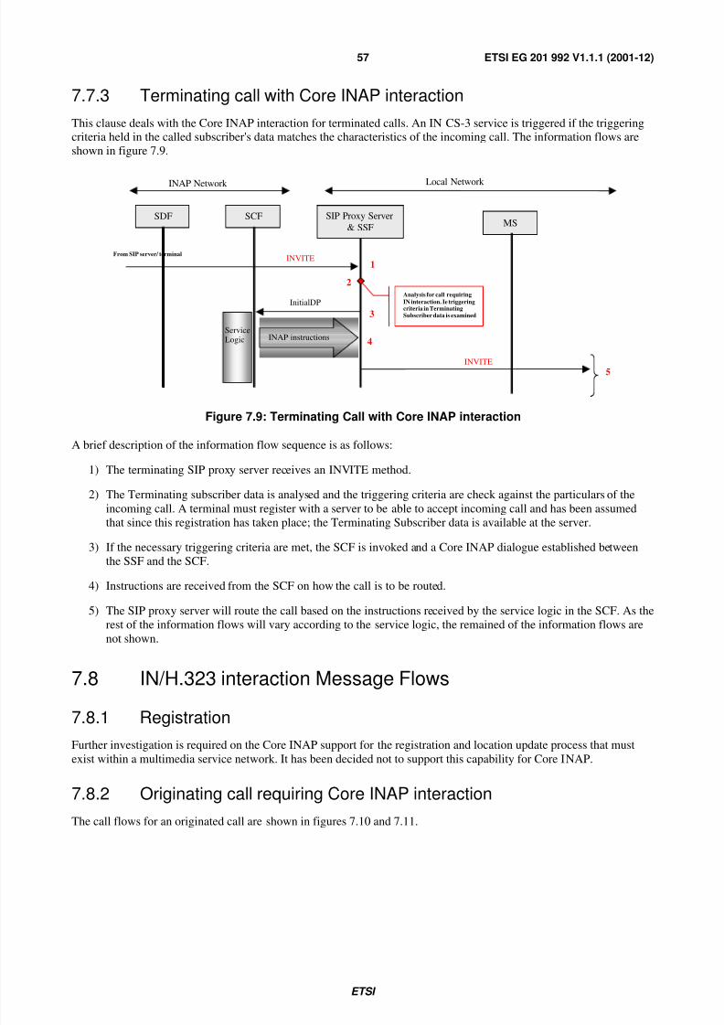
7 Signalling Requirements ........................................................................................................................48 7.1 Introduction ........................................................ ......................................................... .....................................48 7.2 IN based service for dial-up internet access ....................................................... ..............................................48 7.3 Information flow for Click-To-Dial (CTD) service................................................ ..........................................50 7.4 Information flow for Click-To-Fax (CTF) service ................................................... ........................................51 7.5 Information flow for Internet Call Waiting (ICW) service................................................ ...............................52 7.6 Example information flows of in-ip telephony interworking ........................................................ ...................54 7.6.1 Information flow for H.323 terminal originated number translation service ........................................... ...54 7.6.2 Information flow for GW Initiated number translated service......................... ...........................................55 7.7 IN interaction with SIP call control message flows............................................................ ..............................55 7.7.1 Proposed registration process ............................................... ..................................................... .................55 7.7.2 Originating call with Core INAP interaction .............................................................................. ................56 7.7.3 Terminating call with Core INAP interaction.............................................................................. ...............57 7.8 IN/H.323 interaction Message Flows ............................................... ...................................................... ..........57 7.8.1 Registration.................................................................................................................................................57 7.8.2 Originating call requiring Core INAP interaction....................................... ................................................57 7.8.3 Terminating call requiring Core INAP interaction ......................................................................... ............60
8 Security aspects ......................................................................................................................................61 8.1 Introduction ........................................................ ......................................................... .....................................61 8.2 Requirements on the IN/IP interface ..................................................... ...........................................................61 8.3 Requirements on the IN domain......... ....................................................... .......................................................61 8.3.1 Core INAP SCF to SSF interface........................................................... .................................................... .61 8.4 Requirements on the IP Domain....................................................... ....................................................... .........62
Annex A (informative): Bibliography...................................................................................................63
History ..............................................................................................................................................................64
IPRs essential or potentially essential to the present document may have been declared to ETSI. The information
pertaining to these essential IPRs, if any, is publicly available for ETSI members and non-members, and can be found
in ETSI SR 000 314: "Intellectual Property Rights (IPRs); Essential, or potentially Essential, IPRs notified to ETSI inrespect of ETSI standards", which is available from the ETSI Secretariat. Latest updates are available on the ETSI Web
server (http://webapp.etsi.org/IPR/home.asp).
Pursuant to the ETSI IPR Policy, no investigation, including IPR searches, has been carried out by ETSI. No guaranteecan be given as to the existence of other IPRs not referenced in ETSI SR 000 314 (or the updates on the ETSI Web
server) which are, or may be, or may become, essential to the present document.
Foreword
This ETSI Guide (EG) has been produced by ETSI Technical Committee Services and Protocols for Advanced
Networks (SPAN).
Introduction
The present document is closely aligned with ITU-T Recommendation Q.1244 [19], such that clauses 5 and 7 are
similar in technical content with the related parts of the ITU-T Recommendation. Clause 6 whilst aligned with ITU-T
Recommendation Q.1244 [19] provides more detail in the figures and tables describing the relationship of the reference
scenarios with the lower layer transport protocols. The intention of the present document is to define a set of
enhancements for IN CS-3 for interworking with IP-networks, which comprises IN CS-4 in the ITU-T. In ETSI these
enhancements will be considered as a revision of ETSI Core INAP.
The present document describes the standardization of functions to allow interworking between Intelligent Networks
and IP-networks for IN CS-3. These functions include:
- Signalling Requirements for interworking between functional entities in the IN and IP-networks;
- Signalling Requirements to support benchmark capabilities between functional entities in the IN and
IP-networks;
- Architecture supporting the transport of higher layer session multimedia protocols between IP-network and the
Circuit Switched Network;
- Interworking and addressing of service control functions and service control gateway functionality across IN and
IP-network boundaries;
- Study of the security aspects.
The present document only considers scenarios for interworking IN CS-3 capabilities and IP-based networks. Serviceand network integration is outside the scope of the present document.
The management functional entity requirements and interfaces are outside the scope of the present document.
2 References
The following documents contain provisions which, through reference in this text, constitute provisions of the present
document.
• References are either specific (identified by date of publication and/or edition number or version number) or
non-specific.
• For a specific reference, subsequent revisions do not apply.
• For a non-specific reference, the latest version applies.
For the purposes of the present document, the following terms and definitions apply:
call: point-to-point multimedia communication between two H.323 endpoints
NOTE: The call begins with the call set-up procedure and ends with the call termination procedure. The call
consists of the collection of reliable and unreliable channels between the endpoints. A call may be directly
between two endpoints, or may include other H.323 entities such as a Gatekeeper or MG. In case of
interworking with some CSN endpoints via a Gateway, all the channels terminate at the Gateway where
they are converted to the appropriate representation for the CSN end system. Typically, a call is between
two users for the purpose of communication, but may include signalling-only calls. An endpoint may becapable of supporting multiple simultaneous calls.
call signalling channel: reliable channel used to convey the call set-up and teardown messages (see ITU-T
Recommendation H.225.0) between two H.323 entities
composite gateway: logical entity composed of a single MGC and one or more MGs that may be reside on different
machines
NOTE: Together, they preserve the behaviour of a gateway as defined in ITU-T Recommendations H.323 [10]and H.246 [8].
GateKeeper (GK): H.323 entity on the network that provides address translation and controls access to the network for
H.323 terminals, Gateways and MCUs
NOTE: The Gatekeeper may also provide other services to the terminals, Gateways and MCUs such as bandwidth
management and locating Gateways.
GateWay (GW): an H.323 GateWay (GW) is an endpoint on the network which provides for real-time, two-way
communications between H.323 Terminals on the packet based network and other ITU Terminals on a switched circuit
network, or to another H.323 Gateway
NOTE: Other ITU-T terminals include those complying with Recommendations H.310 (H.320 on B-ISDN),
NOTE: Servers are either proxy, redirect or user agent servers or registrars [11].
Session Initiation Protocol (SIP): text-based protocol, similar to HTTP and SMTP, for initiating interactive
communication sessions between users
NOTE: Such sessions include voice, video, chat, interactive games, and virtual reality. The IETF SIP working
group is chartered to continue the development of SIP.
terminal: an H.323 Terminal is an endpoint on the network which provides for real-time, two-way communicationswith another H.323 terminal, Gateway, or Multipoint Control Unit
NOTE: This communication consists of control, indications, audio, moving colour video pictures, and/or data
between the two terminals. A terminal may provide speech only, speech and data, speech and video, or
speech, data and video.
User Agent (UA): application which contains both a user agent client and user agent server
User Agent Client (UAC), calling user agent: the user agent client is the functional entity that may initiate a SIP
request
User Agent Server (UAS) called user agent: a user agent server is a server application that contacts the user when a
SIP request is received and that returns a response on behalf of the user
NOTE: The response accepts, rejects or redirects the request. The user agent server is the functional entity that
may initiate a SIP response.
Zone: collection of all Terminals (Tx), GateWays (GW), and Multipoint Control Units (MCU) managed by a single
GateKeeper (GK)
NOTE: A Zone includes at least one terminal, and may or may not include Gateways or MCUs. A Zone has one
and only one Gatekeeper. A Zone may be independent of network topology and may be comprised of
multiple network segments that are connected using routes (R) or other devices.
3.2 AbbreviationsFor the purposes of the present document, the following abbreviations apply:
API Application Programming Interface
ASP Application Service ProviderBCF Bearer Control Function
BCSM Basic Call State Model
BICC Bearer Independent Call Control
C/B GF Call/Bearer Gateway Function
CCF Call Control FunctionCM Call Manager
CORBA Common Object Request Broker Architecture
CSN Circuit Switched Network CTD Click-To-Dial
CTF Click-To-Fax
CTFB Click-To-Fax Back DA-GF Dial Access Gateway Function
DFP Distributed Functional Plane
DN Directory Number
DRC Direct Routed Call
DSS1 Digital Subscriber Signalling system No.1
GCI Global Connection IdentifierGF Gateway Function
GK GateKeeper
GRC Gatekeeper Routed Call
GT Global TitleGW GateWay
HTTP Hyper Text Transfer ProtocolIAP Internet Access Provider
It is intended to support IN CS-3 benchmark services, Internet based service customization and Voice over IP.
4.1 Benchmark servicesList of benchmark services:
- Internet Call Waiting (ICW) Service;
- IN-based NAI/URL Address translation and resolution services;
- IN-based service for Dial-up Internet Access;
- Click-to-Dial (CTD) Service;
- Click-to-Fax (CTF) Service;
- IN-IP Telephony Interworking;
- IN-IP personal mobility service.
4.2 IN-Internet service examples
• Request-to-Call-Back CSN
A user is able to initiate a telephone call by clicking a button during a Web session. The call can be first set up in
the direction of the requester of the call, or first be set up in the direction of the party the requester wants to be
connected to. E.164 addressing for both A-party and B-party is assumed, and both parties are assumed to be
connected to the Circuit Switched Network. Possible reasons for failures are A-party busy, A-party no answer,
B-party busy, B-party no answer. No detailed notifications are reported back to the requester. An example of an
application of this feature would be on-line shopping: A user is browsing through an on-line catalogue, and
clicks a button thus inviting a call from a sales representative. In the IN the request could be handled depending
on availability of agent, time of day, etc.
• Request-to-Call-CSN
A user is able to initiate a telephone call by clicking a button during a Web session. The requested call is to be
set up between two parties identified by E.164 addresses, which are connected to the Circuit Switched Network.The requester him/herself may or may not take part in the call to be set up. Possible reasons for failures are
A-party busy, A-party no answer, B-party busy, B-party no answer. No detailed notifications are reported back
to the requester.
• Request-to-Call-Back IP
A user is able to initiate a telephone call by clicking a button during a Web session. The call can be first set up in
the direction of the requester of the call, or first be set up in the direction of the party the requester wants to be
connected to. E.164 addressing for both A-party and B-party is assumed, and one or both parties have a VoIPservice. A VoIP user might be a mobile user as well. Possible reasons for failures are A-party busy, A-party no
answer, B-party busy, B-party no answer. No detailed notifications are reported back to the requester. An
example of an application of this feature would be on-line shopping: A user is browsing through an on-line
catalogue, and clicks a button thus inviting a call from a sales representative. In the IN the request could be
handled depending on availability of agent, time-of-day etc.
• Request-to-Call IP
A user is able to initiate a telephone call by clicking a button during a Web session. The requested call is to be
set up between two parties identified by E.164 addresses, where one or both parties have a VoIP service. A VoIP
user might be a mobile user as well. The requester him/herself may or may not take part in the call to be set up.
Possible reasons for failures are A-party busy, A-party no answer, B-party busy, B-party no answer. No detailednotifications are reported back to the requester.
• End User Service Data Customization via an IP-network
A service end-user can customize his/her service data, service profile via an IP-network.
NOTE: This feature has been implemented for IN CS-3 for access through PSTN. See SMF - SMF [5].
• Request-to-Fax
A user of an IP-network who does not have access to a fax machine is able to send a fax to a receiver who has
access to a fax machine but not to an IP-network, during a Web session. The receiver is identified by an E.164
number. Possible reasons for failure are receiver busy, receiver no answer. No detailed notifications are reported
back to the requester. An example of an application of this feature would be a hotel reservation form on thewebsite of a travel agent, where the user fills out the form and then clicks a button to request the form to be sent
as a fax to the hotel being reserved.
• Request-to-Fax-Back
An Internet user who has access to a fax machine is able to request (and subsequently receive) to have certain
electronically stored information sent by fax during a Web session. The requester is identified by an E.164
number. Possible reasons for failure are receiver busy, receiver no answer. No detailed notifications are reported
back to the requester.
• Request-to-Hear-Content-from-IP
A user shall have the possibility to have access to Web content by telephone. The user can have a subset of a
Web page content delivered in audio form via telephone. The requesting user has access to an IP-network, and
can invoke this service via a Web session. The receiving user is identified by an E.164 number. Possible reasonsfor failure are receiver busy, receiver no answer. No detailed notifications are reported back to the requester.
• Request-to-Hear-Content-from-CSN
A user shall have the possibility to have access to Web content by telephone. The user can have a subset of a
Web page content delivered in audio form via telephone. The requesting user has access to the Circuit Switched
Network (e.g. PSTN/ISDN), and can invoke this service via the PSTN/ISDN. The receiving user is identified by
an E.164 number. Possible reasons for failure are receiver busy, receiver no answer. No detailed notifications are
reported back to the requester.
• Internet Call Waiting
A user is notified of incoming calls during a Web session and, by clicking a button, is able to instruct the
network on how this cal shall be further processed (e.g. rejected, forwarded to a voice mail system, accepted
with or without interruption of the Web session (in case of acceptance without Web session interruption VoIP is
assumed)). A sub-set of this feature would be just to keep a log of the times a user receives calls during anInternet session.
• Web Controlled PSTN/IP Conferencing Service
Basic Web controlled PSTN/IP conference call, initiation of conference call, adding parties.
• IP Gateway Selection
A service involving a CSN connection to a gateway to an IP-network is provided, making use of a network setup
with several gateways towards the IP domain. An IN service is used to decide on which physical gateway to use,
based among other things on the availability of the gateway, or on its load.
This scenario is applicable for so-called Internet Access Servers (IAS) as well as Voice over IP (VoIP) gateways.
• Call Logging Service
The Call Logging Service gives the ability to the Network Service Provider to provide the Internet user with allincoming related information (e.g., Calling Party Identification, Time Called, etc.) while the user is busy,
i.e. logged on to a Web session, etc. The Network Service Provider offering such a service (i.e., Call Logging
Service) also provides the capability to the user to retrieve such call related information at a later time. The Call
Logging Service is associated with the Internet Call Waiting service offered by the Network Service Provider
and the user must subscribe to these features to avail the benefits of the Call Logging Service. Additionally, a
Network Service Provider may provide the capability to the user to present all incoming call related informationto user (e.g., an IP client).
• NAI/URL Address Translation Service
The following are service features and requirements related to address translation:
- Registration of previously registered IP-addresses of the communicating end systems within IN
infrastructure.
- Registration of mnemonic addresses (e.g., Names) of the communicating end systems infrastructure.
- Optionally, it should be possible to disseminate the registered information to where it is needed, and collect
registered information from other service providers vital for address translation on a global basis.
- E.164 to IP-Address translation result:
For the user with dial-up access to Internet through telephone line, the IP-address is dynamically
allocated. The translation result is provided from Internet to IN;
For the Intranet user, the IP-address is statically allocated and the associated E.164 number is apre-assigned feature number. The translation result is provided from IN to Internet;
- It should be possible for the network to support the following as part of address translation:
Time-of-day translation;
1-to-N address translation;
N-to-1 address translation;
- It shall be possible for the network to allow terminals to register the following:
Table 5.1 provides a summary of the peer-to-peer protocols and the signalling network requirements of IN CS-3 support
of IP-networks, for the functional architecture depicted in figure 5.1.
Table 5.1: Protocols and signalling requirements for IN support of IP-networks
Interface Functional Entities Protocols Reference
IF1 SCF to PINT server SIP(PINT) Protocol Over (TCP)UDP/IP orOver SCCP/MTP
IF2 SRF to PINT server FTP(PINT) Protocol Relayed over (TCP)UDP/IP orOver SCCP/MTP
IF3 SCF to SRF Core INAP Over TC/SCTP/IP orOver TC/SCCP/MTP
IF4 SCF to SSF Core INAP Call orRAS related
Over TC/SCTP/IP orOver TC/SCCP/MTP
IF5 CCF to CCF ISUP Control Plane/BICC orSIP call Control
Over MTP or SCTP/IP orSSCOP/IP
IF6 SCF -to SA-GF Service Provider ApplicationAPI
Over TC/SCCP/MTP
IF7 SA-GF to GF forDistributed Service Logic
Service Provider ApplicationAPI
Over SCTP/IP
IF8 SCF to SPIRITS client SIP (SPIRITS) Over (TCP)UDP/IP orOver SCCP/MTP
IF9 SPIRITS client to SPIRITSproxy
SIP (SPIRITS) Over (TCP)UDP/IP orOver SCCP/MTP or
Over SCTP/IPIF10 SPIRITS proxy to
SPIRITS serverSIP (SPIRITS) Over (TCP)UDP/IP or
Over SCTP/IP
NOTE 1: This architecture can be deployed entirely within an ISDN/PSTN or IP-network or a combination of both.
NOTE 2: The SRF is independent of the classical IN- or IP domain if may be located on either side of the
functional architecture. It location will impact the protocol stack used to control this entity.
NOTE 3: IF5 is illustrated since it indicates Call Control across this reference point, these Call Control requirementare required as they give rise to the Call States which result in the IN triggering conditions.
5.3 New functional entity requirements
The following new functional entities are required:
- PINT server;
- Service Application Gateway Function (SA-GF);
- Session Manager (SM);
- SPIRITS client;
- SPIRITS proxy;
- SPIRITS server.
5.3.1 PINT server
A PINT server accepts PINT requests from PINT clients. It processes the requests and returns responses to the clients.
A PINT server may perform these functions as a proxy server or a redirect server. A proxy server makes requests to
another PINT server on behalf of its clients; a redirect server returns to its client's addresses of other PINT servers to
which requests can be redirected. The gateway capability includes the ability to communicate with a so-called
Executive System located outside the IP-network domain that will actually perform the service call requested by a PINT
Additionally, this function transfers data (e.g. fax data) between IP-networks and the IN, and associates IP-network
entities with the related entities in gateway function. This function is situated at the edge of the IP-network domain,
where the Application Association with PINT client/server is subject of standardization of the IETF PINT work group
and where the Application Association with SCF in the IN domain.
The functions related to PINT server are:
- In case the Executive System is an IN system, the PINT server delivers received PINT requests to the SCF. Itprovides the SCF with the necessary information to control service requests, identify users and authenticate data,
and protect the IN from misuse or attacks from the IP-network. Furthermore, it hides the SCF/SRF from entities
in the IP-network domain and acts as a mediation device between the IP-network and the IN.
- It also relays requests from an SCF to the IP-network domain to perform services (e.g. user notification).
5.3.2 Service Application Gateway Function (SA-GF)
The Service Application Gateway Function (SA-GF) allows the interworking between the IN service control layer and
the Distributed Service Logic applications (API based functions) in IP domain.
For IN CS-3, on the application level, the types of API based functionality may include:
- CORBA platforms;
- JAVA platforms;
- JAIN platforms;
- Other API based platforms.
Additionally this functionality may provide protocol mapping/service mediation.
5.3.3 Session Manager (SM)
The Session Manager (SM) is responsible for managing the IP-network services. On the IP side it exposes theRegistration interface, but one cannot assume that service interactions are only based on Registration flows. The SM
may initiate activities caused by call control signalling events, in case of collocated SM and CM. The SM shall
participate in domain/zone management and call signalling.
General functions that need to be supported by this SM:
- Service Profile Data filtering/parsing/mapping;
- Security/Authentication;
- Real Time data collection (billing/parsing);
- Triggering of services (in the IN domain or in the IP-network domain);
- Configuration/dimensioning;
- Flow control.
This entity is responsible for passing registration and admission related information to and from IN service layer,namely the SCF. As such, the SM may contain an SSF-like functionality or subset thereof, to model the pre- and
post-conditions that are required to interact with an SCF.
5.3.4 SPIRITS client
SPIRITS client is responsible for receiving PSTN requests from the SCF as well as sending responses back. It may be
co-located with the SCF. If not, it communicates with the SCF via the IF8 interface.
SPIRITS proxy, which serves as an intermediary between the SPIRITS server and SPRITS client and may be co-locatedwith the PINT Gateway. It communicates with the SPIRITS server via the IF9 interface and the SPIRITS client via the
IF10 interface.
5.3.6 SPIRITS server
SPIRITS server, which terminates PSTN requests and is responsible for all interactions (e.g. incoming call notification
and relaying the call treatment) between the subscriber and the SPIRITS proxy via the IF10 interface.
5.4 Extensions to existing functional entity requirements
Necessary extensions to existing IN functional entities are required, these include:
- Specialized Resource Function (SRF);
- Service Control Function (SCF);
- Service Data Function (SDF);
- Service Switching Function (SSF);
- Call Control Function (CCF).
5.4.1 Specialized Resource Function (SRF)
This function has to be extended by capabilities to exchange data with gateway functions to IP-networks. Additionally,
for some of the services it needs to support specialized resources with media transformation functions such as:
- Text-to-fax;
- Text-to-speech, see [4];
- Speech-to-text;
- Fax-to-text;
- IP voice coding to PSTN voice coding conversion;
- IP packet data to PSTN voice coding conversion;
- IP packet data to PSTN/ISDN fax coding conversion.
This network-based enhanced SRF may also be referred to as a Media Resource Function (MRF), see [15]. The
implementation of the MRF will include a resource control interface (e.g. enhanced Core INAP, MEGACO, JAIN, etc.)
and a call control interface (e.g. ITU-T Recommendation H.225.0 [6] or SIP) when based in the network.
5.4.2 Service Control Function (SCF)
Extensions or impacts are for further study.
5.4.3 Service Data Function (SDF)
For some services there may be a need for the SCF to access a database type of entity with service related information
to be shared between the IN and the IP-network. (As for Internet dial-up access, Internet Call Waiting, such as the
association between a PSTN number and an IP-address, etc.)
Therefore the functionality - "SDF contains data pertaining to modem usage/available factor for Internet dial-upaccess" - needs to be added to the SDF description.
The enhanced SSF interacts with the SCF (the IN CS-3 SCF via Core INAP) and the CCF (the IP representation of theCCF) mapping the Call Control Protocol into the Core INAP events trigger points and procedures, where applicable.
The relationship of the SSF to the classical SSF is as follows:
• Many processes, such as call control, database and billing are retained or enhanced;
• Triggering of services (in the IN domain or in the IP-network domain);
• Feature Interaction Management.
NOTE: The Click to Dial type of services can be supported based on IN CS-3 capabilities.
5.4.5 Call Control Function (CCF)
CCF is an enhanced functional entity, responsible for handling call signalling on either network. The CCF
communicates with the SM using registration and admission capabilities. To support ISUP signalling, the CCF has to
implement H.246 [8], annex C. In that case it appears to the IN side CCF as being another CCF. This functionalityincludes handling the management of the call processing, and call signalling.
This entity is responsible for passing service related information to and from IN service layer, namely the SCF, and
managing the service control relationship. As such, the CCF may contain an SSF-like functionality or subset thereof, to
model the pre- and post-conditions that are required to interact with an SCF.
The CCF could be seen as a logical switch including call control signalling (e.g. ITU-T Recommendation H.225.0 [6])
and connection control signalling (see ITU-T Recommendation H.245 [7]) for VoIP is transferred via the MM-GF,
which makes network routing decisions.
The CCF can require SCF assistance for these routing decisions, e.g. for number translation services, number
portability, user profile consultation, VPN support.
The functions related to the CCF are:
• Interworking for:
- Number portability;
- Number translation services;
- user profile consultation;
- VPN support;
- OAM;
• General functions that need to be supported by this function:
- Data filtering/parsing/mapping;
- Security/Authentication;
- Real Time data collection (billing/parsing);
- Configuration/dimensioning;
• Flow control;
• Circuit switching and ancillary processes are removed;
• The H.323 or SIP server interworking functions are added.
The CCF, as shown in figure 5.2, also contains a (RM) resource manager function, analogous to the high layer resourcecontrol function in the decomposed H.323 version 4 gateway. This MGC like function is responsible for controlling the
lower layer resource control function in the decomposed H.323 version 4 gateway, commonly referred to as MG. An
example of a protocol on this reference point is the H.248 Media Gateway Control Protocol. This functionality includes
handling the management of the logical channels, e.g. H.245 control signalling.
The RM part of the CCF could be seen as a logical Bearer Control Function (BCF). When using connection control
signalling (H.245) for VoIP that is transferred via the CCF, the CCF makes network routing decisions.
It is recognized that Core INAP interacts with and maps to the underlying call control signalling (e.g. Q.931, ISUP,
BICC, H.225.0 and SIP) in the CCF. The call control may invoke H.248 media and connection operations, for legs,
media, packages independent of before or after the IN interaction. Where a Call Control protocol is encapsulated in an
H.248 package, mapping to this package or to the embedded protocol may also need to be specified:
- Physical Location: The H.323 Gatekeeper/SIP server and SSF, which may be located in any network since Core
INAP signalling is standardized for international use. And is call control protocol independent.
- Physical Realization: From the control of VoIP viewpoint the Service Capability server and the H.323
Gatekeeper/SIP server may be combined in one network entity or may be separate in separate network entities. If
they are separate, standardization of the interface may be required.
- IP PDU Routing: For the routing of IP call control packets to/from the H.323 Gatekeeper/SIP proxy server it is
simply assumed that appropriate addressing and routing takes place.
This interface reflects an extension of the existing SCF-SRF relationship. It is used to request the SRF by the SCF toretrieve the appropriate data from the gateway function. This may require transfer of correlation information to address
the GF and the appropriate data. In addition, the SCF instructs the SRF to transform the retrieved data into other formats
and to transfer this data over the PSTN/PLMN to the end user.
This interface will require enhancements to the existing ITU-T standard for this reference point (see ITU-T
Recommendation Q.1231 [5]).
5.5.4 IF4: SCF to SSF interface
This interface reflects the requirement to carry an IN-based signalling protocol for IP and Multimedia services. This
interface relays the IP Multimedia control plane triggered events to and from the SCF.
This interface is required to trigger and control value added services from a SIP proxy or H.323 gatekeeper function in
the IP-network e.g. for multimedia access from the Internet "dial-up" access.
This interface may require standardization.
5.5.5 IF5: CCF to CCF interface
This interface reflects the requirement to carry an ISDN control plane signalling protocol for Multimedia services. This
interface relays the IP Multimedia user plane received from the CCF. This interface is required for VoIP-based services.
This interface may require standardization but is not expected to be IN specific.
5.5.6 IF6: SCF to SA-GF interface
This interface reflects the requirements pertinent to the IF6 interface. However, the possibility of physically orfunctionally co-locating these functional entities would remove this from standardization.
5.5.7 IF7: SA-GF to GF for distributed service logic platforms interface
The SA-GF to Distributed Service Logic Platforms interface represents standard APIs allowing an Application Service
Provider (ASP) to control defined capabilities offered by the underlying network via the SA-GF. The service logic
execution of the application offered by the ASP typically is located in a separated domain than the SA-GF offering the
API.
5.5.8 IF8: SCF to SPIRITS client interface
This interface is for communications between the SCF and the SPIRITS client. Specifically, from the SCF to the
SPIRITS client, the parameters associated with the applicable IN triggers are sent. From the SPIRITS client to SCF, the
subscriber's call disposition is sent. The SCF "transforms" the user's disposition into appropriate actions, such as playingan announcement to the caller, and resuming the suspended call processing in the SSF.
5.5.9 IF9: SPIRITS client to SPIRITS proxy interface
This interface is used for communications between the SPIRITS client and SPIRITS proxy. The SPIRITS proxy may in
turn communicate with the SPRITS server, or may act as a virtual server, terminating the requests without sending them
down to the SPIRITS server.
5.5.10 IF10: SPIRITS proxy to SPIRITS server interface
This interface serves two main purposes:
1) to notify the subscriber of incoming calls together with the calling number and name, if available; and
2) to send to the SPRITS proxy the subscriber's choice of call disposition specified in real-time.
5.6 Lower layer protocol gateway and mapping functions
5.6.1 Introduction
The following lower layer protocol gateways, mapping functions may be required depending on the protocol
architectures employed in each domain. If required these functions will be implied at the CSN/IP domain boundary.These functions include:
- Signalling Gateway Function (S-GF);
- Service Control Gateway Function (SC-GF);
- Dial Access Gateway Function (DA-GF);
- Media Manager Gateway Function (MM-GF).
5.6.2 Lower layer protocol functional model
Figure 5.3 illustrates the functional architecture depicting the lower layer functional interface requirements to supportthe higher-level functional interfaces (illustrated in figure 5.1). This diagram is a subset of the generic DFP model forIN CS-3. Note that this architecture can be deployed entirely within an ISDN/PSTN or IP-network or a combination of
both.
IFa
IFb
Service/Application Layer
Call/Bearer Layer
Intelligent Network IP Network
PINT server SCF
Legend: Signalling
User Data
CCF
SC-GF
SM SSF
IFc
IFg
IFf
IFd
IFe
IFj
IFk
SDF
SRF
CCF
SSF
MM-GF
S-GF RM
CM
IFh
IFi
DA-GF
Figure 5.3: Lower layer protocol and mapping functional architecture for IN support of IP-networks
This interface will support the lower layer transport requirements of the IF1 and IF2 interfaces (see clauses 5.4.1 and5.4.2). The IFh interface will transport:
- the SCF with service requests, to allow the SCF to instruct the collection of information necessary to execute the
service (identity, charging and authenticity information) requests, and to control the gateway during serviceexecution to the IP-network via the SC-GF;
- the data connection establishment requirements and the data exchange data between the SRF and the PINT
server via the SC-GF.
This interface may require ITU-T standardization co-operatively between the IETF and the ITU-T, to reflect the
requirements pertinent to the IFh reference point.
5.7.9 IFi: SC-GF to SSF interface
This interface reflects the requirement to carry an IN-based signalling protocol for Multimedia services. This interface
relays the IP Multimedia user plane. This interface supports the IF7 interface (see clause 5.4.7).
This interface is required to trigger and control value added services from a SIP proxy or H.323 gatekeeper function in
the IP-network e.g. for multimedia access from the Internet "dial-up" access.
This interface may require standardization.
5.7.10 IFj: S-GF to CCF-CM interface
This interface reflects the requirement to carry an IP control plane signalling protocol for Multimedia services. This
interface relays the ISDN Multimedia user plane received from IFc.
This interface is required for Voice over IP-based services.
This interface may require standardization but is not expected to be IN specific.
5.7.11 IFk: MM-GF to CCF-RM interface
This interface reflects the requirement to carry an IP Media Gateway Control Protocol (e.g. H.248) for Multimedia
services. This interface relays the ISDN Multimedia user plane received from IFe.
This interface is required for Voice over IP-based services.
This interface may require standardization but is not expected to be IN specific.
6 IN/IP Implementation Scenarios6.1 IN/IP interworking for IN CS-3 to support SIP systems
To provide a better understanding of the applicable SIP-based call control network architecture, the SIP-based call
control functional entities are introduced, which may be contained within SIP entities as defined in [11]. This is an
attempt to accommodate the new concept of a decomposed SIP Call Control proxy, defined in ITU-T Recommendation
H.248 [9], and the applicable bearer control configurations, which may utilize bearer control protocols from BICC or
H.245 as required from various protocol related studies.
The functional names have been chosen with the intent of minimizing confusion. They do not intend to imply a specific
The SIP protocol has five functional elements defined in [11]:
- User agent client;
- User agent server;
- Proxy server;
- Redirect server;
- Registrar server.
6.1.2 SIP Call call models
In SIP-based systems a SIP proxy with call control intelligence is defined. This intelligence will enable nominated SIP
proxies to locate and retain significant call control state. This will enable standards to be developed to synchronize theSIP Call State model with the IN Basic Call State Model (BCSM) as defined in ITU-T Recommendation Q.1224 [4]
and Q.1237/Q.1238. In essence the proxy server is comprised of both a SIP client and a SIP server. It is required to
analyse which BCSM states have meaning in a SIP-based service context, and how bearer and multimedia support can
be added to both this SIP call model and understood in the extension of the IN call control model.
6.1.3 Functional model
Figure 6.1 shows the functional model involving IN and SIP interworking supporting the high-level
functions/applications. Figure 6.2 shows the functional model involving the low-level interworking and protocolmappings.
As indicated above (see clause 6.1.2), possible groupings in Intelligent SIP proxy are depicted [11]. It should be noted
that the single Intelligent SIP proxy as modelled in these figures can in fact represent several different physical
instances in the network. For example with one Intelligent SIP proxy in charge of the terminal or access
network/domain, and another in charge of the interface to the CSN.
IF3
IF5
Service/Application Layer
Call/Bearer Layer
Intelligent Network IP Network
SDF
IF4 SRF
SCF
CCF
SSF
Legend: SignallingUser Data
SIP TE UA
Intelligent SIP proxy
SM CCF
SSF
Figure 6.1: A SIP-based call control configuration using an intelligent SIP proxy (high-level)
6.1.4 Requirements for IN-interaction with SIP-based systems
Functional requirements for the IN Interaction with SIP-based systems are listed below:
• Currently, there is a lack of requirements showing the need to support the Registration, Call Control, Media
Control (e.g. H.248) and H.245 Bearer Control, this must be addressed.
• It is considered vital to address the required service features and functional network capabilities for the support
of interworking at the various proposed functional entities and the states requires.
• Relationship of SSF and CCF to the new functional entities introduced in ITU-T Recommendation Q.1244 [19]
(DFP for IN CS-3) to decompose the SIP proxy (i.e. Session Manager (SM) and Call Manager (CM)).
• Functional interaction between SM and CM depending on the various SIP-based call scenarios.
• Mapping of SIP Registration and Call Signalling messages to Core INAP operations.
• Exact set of SIP Registration functionality which needs to be visible to IN (i.e. need to be monitored or
manipulated), if any. This includes the considerations on the kind of modelling required.
• Possible Separation of the CCF/SSF into different physical entities.
• The use of multiple SSFs, where one SSF may model the SIP Registration protocols and another SSF model the
SIP Call Control procedures, require consideration. These SSFs may be physically distributed.
• The configuration of trigger conditions in the SSF, use of managed trigger data from the SCP in the IN domain.
• The same CCF/SSF triggering mechanism applies to processing SIP-based/IN-based call. SSF is located at
Intelligent SIP proxy to interact with SCP in IN domain.
• Mapping of the SM to the SSF (like IN FE) and mapping the CM to the CCF.
• For a GW originated IN-based call, the SIP registration server and the SSF may be distributed in different
Intelligent SIP proxy entities. In this case, dynamic DP arming should be supported at MGC under the control of
the Intelligent SIP proxy SM.
• The definition of state driven events in the SIP Registration and SIP Call Control Protocols and their relationshipto the SM/CM functions. How these states map into the current IN BCSM models; all require consideration.
• The SCF will be able to select one or more appropriate SSF/Intelligent SIP Proxies dependant on different
parameters (class of service requested by the user, placement of gateways, tariff, etc.). The SC-GF will be able to
perform the correct lower layer protocol and address translation functions.
• The SC-GF will allow interworking with several SSF/Intelligent SIP Proxies.
• The interface between the H.323 Gatekeeper/SIP server and the SSF call control processes must:
- Carry sufficient call data for the SSF to function correctly and to deliver the necessary information to the
SCF so that service logic decisions can be made;
- Allow the SCF to control VoIP calls (e.g. change B-party address) and manipulate call information (such as
presentation number).
• It is proposed that the CCF/SSF interface is presently not the subject for standardization. However, a mapping of
parameters may be required to demonstrate the mapping in the SSF to the H.323 Gatekeeper/SIP proxy server
call control protocol, states and events. Thereby enabling the CCF to model either a H.323 Gatekeeper or a SIP
proxy server.
User Interaction requirements for the IN Interaction with SIP-based systems are listed below:
• Intelligent SIP proxy enhancements for user interaction (e.g. does it provide control of the speech path
connection and information on tones and announcements).
• Handling of SRF functionality and necessary enhancements of H.248 to support this case shall be provided as
• The user interaction with the SIP User Agent (UA) at the terminal may be realized through a SIP Registration
interface. The user interaction with PSTN user is realized using MGC relay mode. The information exchange
path is Intelligent SIP proxy to GW interface SIP Registration and H.248 respectively. SRF functionality resides
in GW and is controlled by H.248.
• The SIP Registration interface may be modified to support user interaction information exchange. A SIP
Registration interface between Intelligent SIP proxy and SIP terminal could be upgraded to supportcall-unrelated user access service.
• User interaction using http is shown in annex K of ITU-T Recommendation H.246 [8], or by using the payload
capabilities of SIP Call Control in SDP, these options for user interaction need consideration.
Initial working assumptions:
• In order to fully extend the IN-based value-added services, it is recommended to use the Monolithic IntelligentSIP proxy as shown in figure 6.4 above.
• User interaction capability with SIP terminal is required. It may be realized by different options, e.g. by
enhanced SIP Registration or by an enhanced SIP Call Control protocol.
6.1.5 SIP assumptions architecture and implementation issues
6.1.5.1 IN-SIP interaction
This clause investigates the possibility of IN CS-3 service control based on the SIP proxy server approach. This means
that a locally configured proxy server is required for outgoing calls that require legacy service support based on existing
IN CS-3 services. In particular it provides a proposal for the triggering of IN CS-3 services as well as a mapping
between the IN CS-3 call states and the call states of the Session Initiation Protocol (SIP).
An overall objective is to demonstrate that IN CS-3 control of VoIP services in networks can be readily specified and
implemented by adapting standards and software used in the present networks. This approach leads to services that
function the same when a user connect to present or future networks, simplifies service evolution from present to future,
and leads to more rapid implementation.
Clause 6.1.5.2 provides a brief description of the concepts for IN service triggering based on IN CS-3 subscriptioninformation.
Clause 7.7 provides information on the following:
- A description of a registration process (see clause 7.7.1);
- A description of triggering services for Originated Calls (see clause 7.7.2);
- A description of triggering for Terminated calls (see clause 7.7.3).
Figure 6.3 specifies the proposed IN/IP architecture based on the IETF IP architecture [14].
The process how to handle the registration process needs further study in conjunction with the API methods presentlystandardized and the mapping to the SIP/SDP procedures and extensions.
Subscribers may register in the SIP network allowing the subscriber to receive incoming calls. A subscriber may use anadditional identifier (e.g. MSISDN) in the registration process. Upon registration with the server, the subscription
information for the subscriber is sent to the SSF by the SDF in the subscriber's home network. As incoming calls made
to the subscriber terminate at the server the subscriber is registered with, the Terminating Subscription Information may
be examined and if necessary the SCF may be invoked on a per incoming call basis. Similarly, calls made by a
subscriber already registered with a proxy server allow the Originating subscription information to be examined and
potentially allow the SCF to be invoked. Callers not registered will not have any subscription information in the proxy
server they are using to place the call.
The proposal here is as follows: when the initial call request message (or the INVITE method) is received by the SIP
proxy server, the SSF establishes a dialogue with the SDF of the home subscribers network to allow the subscription
information to sent. The Originating subscription data may then be examined and if necessary the SCF may be invoked.
6.1.5.3 Assumptions
a) All the call flows show that the SIP proxy server and the SSF have been co-located in order to avoid showing
information flows between the two entities. Standardization of the messages for this interface is for further study.
b) Originating and terminating SIP proxy servers must operate in a call-state aware mode.
c) As registration with a SIP proxy server is not mandatory, it shall be possible to determine whether a registration
exists for that particular subscriber when a subscriber places an incoming call. This allows the subscriber data
information to be fetched from the home SDF if the subscriber is not registered.
NOTE: Absence of the originating subscriber data does not necessarily mean that the user is not registered,
merely that the originating subscriber data may not exist for that subscriber.
d) The information flows make no consideration for interworking with other networks (e.g. PSTN via gateways).
6.2.3 Requirements for IN CS-3 interaction with H.323 system
Functional requirements for the IN CS-3 interaction with H.323 systems are listed below:
• Currently, there is a lack of requirements showing the need to support the Protocols, RAS, H.225.0 Call Control
and H.245 Bearer Control, this must be addressed.
• It is considered vital to address the required service features and functional network capabilities for the support
of interworking at the various proposed functional entities and the states required.
• Relationship of SSF and CCF to the new functional entities introduced in ITU-T Recommendation Q.1244 [4]
(DFP for IN CS-3) to decompose the Gatekeeper and Media Gateway Controller (i.e. Session Manager (SM) and
Call Manager (CM)).
• Functional interaction between SM and CM depending on the various H.323 call scenarios (i.e. GRC scenario,
DRC scenario).
• Mapping of H.225.0 RAS and Call Control signalling messages to Core INAP operations.
• Exact set of RAS functionality which needs to be visible to the IN (i.e. need to be monitored or manipulated), if
any. This includes the considerations on the kind of modelling required.
• Possible Separation of the CCF/SSF into different physical entities.
• The use of multiple SSFs, where one SSF may model the RAS protocols and another SSF model the Call Control
procedures requires consideration. These SSFs may be physically distributed.
• The configuration of trigger conditions in the SSF, use of managed trigger data from the SCP in the IN- domain.
• The same CCF/SSF triggering mechanism applies to processing H.323 IN-based call. SSF is located atGatekeeper to interact with SCP in the IN domain. CCF may be located in Gatekeeper or MGC in the GRC
model scenario.
• Mapping of the SSF and CCF functions in the CM and possibly in the SM for RAS purposes.
• For GW originated IN-based call, SSF and CCF will be distributed in different entities if the DRC model is used.
In this case, dynamic DP arming should be supported at MGC under the control of Gatekeeper SM.
• The definition of state driven events in the H.225.0 RAS and Call Control protocols and their relationship to the
SM/CM functions. The distribution of these "state machines" between the physical entities GK/MGC requires
consideration. How these states map into the current IN BCSM; all require consideration.
• The SCF will be able to select one or more appropriate SSF/H.323 GKs dependent on different parameters (class
of service requested by the user, placement of gateways, tariff, etc.). The SC-GF will be able to perform correct
lower layer protocol and address translation functions.
• The SC-GF will allow interworking with several SSF/H.323 Gatekeepers.
• The interface between the H.323 Gatekeeper/SIP server and the SSF call control processes must:
- carry sufficient call data for the SSF to function correctly and to deliver the necessary information to the SCF
so that service logic decisions can be made;
- allow the SCF to control VoIP calls (e.g. change B-party address) and manipulate call information (such aspresentation number).
• It is proposed that the CCF/SSF interface is presently not the subject for standardization. However, a mapping of
parameters may be required to demonstrate the mapping in the SSF to the H.323 Gatekeeper/SIP proxy server
call control protocol, states and events. Thereby enabling the CCF to model either a H.323 Gatekeeper or a SIPproxy server.
6.2.4.2 Architecture and assumptions for IN CS-3 interaction with H.323 call control
Clause 7.6 provides information flows that illustrate simple Originating and Terminating calls with CoreINAP
interactions.
The assumptions are:
a) The call flows presented are based on using the ITU-T Recommendation H.323 [10] protocol between the ISDNGateway/endpoint and the Gatekeeper;
b) The gatekeeper and the SSF have been co-located in order to avoid any showing information flows between thetwo entities;
c) The information flows make consideration for interworking with PSTN/ISDN media gateways.
6.3 IN/IP interworking for IN CS-3 to support PINT basedservices
From IETF documents ([11], [12] and [13]) there are a number of entities that can interact using the PINT IP protocol.These entities are:
- Proxy server;
- Redirect server;
- Registrar server;
- Gateway;
- Notification Receiver (potentially);
- User agent server; and
- Specific to PINT, a "pure" client.
Of these entities, all are completely within the IP-network, with the exception of the PINT Gateway, which exists at the
edge of the IP-network.
Note that the PINT Gateway is a PINT server which has the ability to deliver a PINT request received from the
IP-network to a "Executive System" located in the PSTN and to deliver PINT responses received from the "ExecutiveSystem" to the IP-network respectively.
As described in [12] and [13], the PINT Gateway terminates the message flows with the other IP-based network
entities. It also communicates with the IN CS-3 SCF, presenting an abstraction of this to the IP-based network entities
as an "Executive System". It transfers data objects (or "content") from the IP-network along with requests, and returns
responses to the IP-network requesting PINT clients. As such, it acts as a mediation device between the IP-network and
the IN. The PINT Gateway Function is required in all PINT service transactions (see figure 6.8).
IFa SCF to PINT Gateway IF1, IF4 over SCCP/MTP orover (TCP)UDP/IP
IFb SRF to PINT Gateway IF2 Over SCCP/MTP
IFh PINT Gateway to PINTproxy/client
IF1, IF2 Over (TCP)UDP/IP
The following information can be exchanged between the IN and the Internet:
- Internet/Intranet user on-line status information;
- Service data customization information.
The SIP/SDP(PINT) protocols/service profiles are carried from IF1 and mapped over ISDN lower layer protocols SCCP
and MTP, possibly including TC. SCCP routeing can also be used to route control messages to the SCF, using the
IP-address by translating it to a SCCP SPC or GT. It may also route content based messages to the SRF utilizing the
IP-address, by translating it to an appropriate SCCP SPC or GT.
An integral part of the PINT service protocol is the Managed Information Base (MIB). The associated MIB defines the
parameters that can be monitored on the user or PINT client or PINT Gateway basis for security or performance
purposes.
6.4 IN/IP interworking for IN CS-3 to support SPIRITS basedimplementation of services
The SPIRITS Architecture [14] is supporting services originating in the PSTN and necessitating the interactions
between the PSTN and an IP-network to support services, for example:
• Internet Call Waiting (ICW);
• Internet Caller-ID Delivery;
• Internet Call Forwarding;
• Internet user incoming call related information:
- Notification: From IN to Internet;
- Acknowledgment: From Internet to IN.
Figure 6.11 shows the functional model involving IN and SPIRITS the high-level interworking for a hybrid
configuration.
It is important to note that the subscriber activates a SPIRITS service by an act of service registration for a later session,which can take place anytime after the subscriber is connected to an IP-network (such as the Internet). The subscriber
may specify the life span of the session. As soon as the session ends, the SPIRITS service is deactivated. Naturally, the
subscriber should also be able to deactivate a SPIRITS service anytime during the service session. Service registration
and service de-registration are supported by PINT capabilities and PINT-related functional elements. This hybrid
scenario enables more complicated services e.g. ICW, to be implemented.
Figure 6.13: SPIRITS example configuration (high level)
6.5 IN/IP interworking for IN CS-3 to support distributed servicelogic servers via an API
At present there are two different API specifications being developed, the first is designed for use within a mobile
environment (access to applications within a Virtual Home Environment) this can be found in [9] and [10]. The other
concerns a more general API whose design has not been limited to any one particular environment as is the case in [9]
and [10]. This specification can be found in [18].
For IN CS-3 on the application level, the types of API based functionality may include, CORBA, JAVA, JAIN
technologies or other API based platforms. Additionally this functionality may provide protocol mapping/service
mediation.
The SA-GF allows either:
- interworking between the Service Control layer in the Intelligent Network and the Distributed Service Logic (see
figure 6.14);
- interworking between the CCF and Distributed Service Logic (see figures 6.15 and 6.16).
NOTE: Interworking of the CCF (representing specific functionality in a VoIP environment, e.g. SIP proxy or
GK) and the SA-GF in the particular VoIP environment is not subject of IN CS-3 standardization.
The SCF to SA-GF interface (IF6) is provided to allow access to distributed service logic via an API. As such, the
"distributed service logic" may be resident within one Network Operators domain, or may be provided by a 3rd partysuch as a Service Provider. Either way the SA-GF will provide the necessary firewall/security functions to protect both
the IN network provider and the 3rd party service logic provider and any protocol mapping functionality deemednecessary. This is represented in Case 1 of figure 6.14.
From an implementation point of view the SA-GF functionality may be co-located with the SCF in the IN domain and a
peer entity providing the necessary firewall capability co-located with the Distributed Service Logic in the IP domain.In this case IF6 would be absorbed by the SCF. This is shown in Case 2 of figure 6.14.
Table 6.9 provides a summary of the peer-to-peer protocols and the signalling network requirements of IN support of
Distributed Service Logic servers, for the functional architecture depicted in figure 6.14.
Table 6.9: Protocols and signalling requirements for IN support of Distributed Service Logic servers
Interface Functional Entities Protocols Reference
IF6 SCF to SA-GF Service Provider ApplicationAPI
Over TC/SCCP/MTP
IF7 SA-GF to GF forDistributed Service Logic Service Provider ApplicationAPI Over SCTP/IP
IF6: SCF to SA-GF interface: This interface reflects the requirements pertinent to the IF6 interface. However, thepossibility of physically or functionally co-locating these functional entities would remove this from standardization.
IF7: SA-GF to distributed service logic platforms: this interface represents standard APIs allowing an Application
Service Provider to control defined capabilities offered by the underlying network via the SA-GF. The service logic
execution of the application offered by the ASP typically is located in a separated domain then the SA-GF offering the
API.
GF: The Gateway function will provide firewall/security functions necessary for the distributed service logic platform.
The interface between the "API for accessing Service Provider Applications" and the IP call control and the distributionof network intelligence are depicted in the network architectures of figures 6.15 and 6.16 depicts. Note that this
architecture can be deployed entirely within an ISDN/PSTN or IP-network or a combination of both.
SC-GF: The Service Application Gateway Function allows interoperability between the SCF in the IN domain and the
H.323 Gatekeeper in the IP domain. For IN CS-3 the standard allowed the SSP to SCP Core INAP TC interface to be
transported over TCP/IP or UDP/IP. These options depended on the services and guarantees provided by the IP-network
architecture that is used to transport the signalling. This case was not specified, but not precluded in IN CS-1:
- The SCF will be able to select one or more appropriate SSF, dependent on different parameters (class of service
requested by the user, placement of gateways, tariff, etc.). The SC-GF will be able to perform correct lower layerprotocol and address translation functions;
- The SC-GF will allow interworking with several SSFs.
6.7 ISDN/IP interworking to support signalling transportfunctionality
The CCF to S-GF interface (IFc) is provided to allow access to call control functionality via an IP-based network. TheS-GF will provide the necessary firewall/security functions to protect both the IN SS7 signalling network and the
IP-based protocol network. The main functions of this gateway are to provide inter-technology firewall functionality
and lower layer protocol adaptation. That is, mapping from an IP-based lower layer protocol (e.g. UDP/IP) to an SS7
based lower layer protocol (e.g. SCCP/MTP). Inter-technology call control signalling translation may also be requiredin certain circumstances. The inter-technology firewall functionality may be intra-network or inter-network provider. In
the case of inter-network firewall functionality the availability of security functions in this entity is critical. This isrepresented in Case 1 of figure 6.18.
From an implementation point of view the S-GF functionality may be co-located with the CCF in the ISDN domain, or
an IP server in the IP domain. In this case IFc would be incorporated into the CCF. This is shown in Case 2 of
figure 6.18.
Case 1
Intelligent Network IP Network
CCF IFc S-GF
Legend: Signalling User Data
IFj
Case 2 S-GF IFj SCF
CCF SM
SSF
RM
CM
CCF SM SSF
RM
CM
Figure 6.18: S-GF implementation low-level cases
Table 6.12 provides a summary of the lower layer protocol and mapping requirements of ISDN/IP interworking to
support signalling transport functionality, for the functional architecture depicted in figure 6.18.
IFc CCF to S-GF IF5 Over MTPIFj S-GF to CCF CM IF5 Over SCCP/MTP or
Over SCTP/IP
IFc CCF to S-GF interface: This interface reflects the requirements pertinent to the ISUP control plane interface
(e.g. ISUP) carried over an SCCP/MTP transport interface. However, the possibility of physically co-locating thesefunctional entities would remove the exposure of this transport layer.
IFj S-GF to CM: This interface reflects the requirements pertinent to the ISUP control plane interface (e.g. ISUP)
carried over a TCP/IP or SCTP/IP transport interface. However, the possibility of physically co-locating these
functional entities would remove the exposure of this transport layer.
S-GF: The Service Application Gateway Function allows interoperability between the Call Control function in the
ISDN and the H.323 Gatekeeper in the IP domain. These options depended on the services and guarantees provided by
the IP-network architecture that is used to transport the signalling:
- The CCF will be able to select one or more appropriate SSF, dependent on different parameters (class of service
requested by the user, placement of gateways, tariff, etc.). The S-GF will be able to perform correct lower layer
protocol and address translation functions;
- The S-GF will allow interworking with several CCF/H.323 Gatekeepers.
7 Signalling Requirements
7.1 Introduction
The examples described in this clause are agreed in to be added to the "function architecture for IN/IP-network
interworking, to outline requirements, to further discussion and to provoke further contribution on the open points:
- the example in clause 7.3 is fairly stable;
- the example in clause 7.4 requires clarification on a number of new proposed procedures;
- the example in clause 7.5 requires clarification on a number of questions and is considered an initial description;
- clause 7.6 gives example information flows for IN/IP Telephony;
- clause 7.7 gives example information flows for IN with SIP call control; and
- clause 7.8 gives example Information flows for IN with H.323 call control.
It is currently being discussed whereby Core INAP/TC(TCAP) may run directly over UDP/IP or SCTP/IP with some
SCCP addressing and signalling routing adaptation layer. UDP/IP or SCTP/IP cannot guarantee delivery of sensitive
Core INAP information via SCCP class 4, (DSS1 via SCCP class 1 or 2).
For current existing IN-based services, our assumption is that there are no Core INAP changes required.
7.2 IN based service for dial-up internet access
The service considered is an IN-based value added service to access to the Internet through the PSTN (dial-up access).
In this example several DA-GF are/may be geographically distributed in the network and that a single number is used
(e.g., an 800 freephone number) to access them. Dialling of this number triggers service logic in the SCP that routes the
call to the appropriate DA-GF. This is based on the geographical location of the calling party and on the availability of dynamic (near real-time) information of DA-GF usage and available.
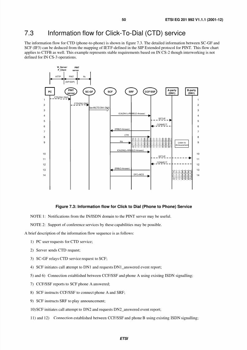
11) SRF reports to SCF the completion of fax sending;
12) SCF instructs to disconnect the connection between DN2 and SRF.
7.5 Information flow for Internet Call Waiting (ICW) serviceTo consider the Internet Call Waiting feature, the Internet access needs to be under the control of the IN. The Intelligent
Network should know that the called telephone number is busy with an Internet Access. Therefore, the information that
an Internet session is in progress must be available to the IN.
One solution could be as follows:
• When a user connects to the for Internet dial-up the IN recognizes an IAP/ISP number or through some othermeans.
It happens either at the CCF/SSF level if the IAP/ISP number is specific or after an interrogation of the SDF if
those numbers are not specific. (In the latter case the SMF is then responsible to update the data in the SDF.)
•DPs are then positioned in order to trigger the address (phone/IP) conversion when an incoming call for theInternet dial-up user is to be terminated.
The information flow for ICW is shown in figure 7.5. The service is triggered by an armed TDP at the Called Party
T_Busy DP.
SETUP
SearchReq (DN1)
SearchRslt ( VoIPaddr )
IDP(T_busy)
Connect (DN3 VoIPaddr )
VoIP
Notify( VoIPaddr DN2)
Notify(DN2) Accept
Accept
SearchReq (SEL,DN1,DN2) SearchRslt (DN3)
ANM Connect
PCM
Bridging conversion
Accept
IAM( VoIPaddr )
Notify( VoIPaddr DN2)
1 2 3
4 5 6 7 8 9
10 11 12 13 14 15
16 17 18 19
1 2 3
4 5 6 7 8 9
10 11 12 13 14 15
16 17 18 19
Registration Req Register( VoIPaddr ,DN1)
Store Server Ipaddr VoIPaddr & DN1 Register( VoIPaddr ,DN1)
Cld _party (DN1) SDF SCF SC-GF ICW
server CCF/SSF Clg _party (DN2) CCF/MG
Figure 7.5: Information flow for Internet Call Waiting
7.6.2 Information flow for GW Initiated number translated service
The same CCF/SSF triggering mechanism applies to processing H.323 IN-based call. CCF/SSF may be located in MGCfor DRC mode call control. The following example assumes that the Gatekeeper is enhanced to relay Core INAP like,
Call Control, Admission and User Interaction, operations to, and from, the MGC for the support of IN triggering for
triggering from the MGC via Gatekeeper. The information flow is shown in figure 7.7.
• In this case, dynamic DP arming should be supported at MGC under the control of Gatekeeper SM.
• New service control interface between GK and MGC should be defined to support information exchange
between SM in GK and CCF in MGC in case that DRC mode is used.
LEGEND:
Existing IF in IN domain New IF (INAP over TCP/IP)
Existing RAS IF Existing H.225.0 control IF
Updated RAS IF Existing H.248IF New Service Control IF
InitialDP InitalDP
Connect(DN1)
ARQ( endpointID =800 ****)
Connect(DN1)
Display(prompt for pwd ) Prompt& CollectUserInformation
Notify( pwd ) CollectedUserInfo
CollectedUserInfo
RequestReportBCSNEvent RequestReportBCSNEvent
ACF( callModel =DRC) SETUP ( cdpN =DN1)
RLC(Cause=user busy) EventReportBSCM
(O_Called_Party_Busy)
Connect(DN2) Connect(DN2) SETUP ( cdpN =DN1)
ALERTING
CONNECT
Connect(DN2)
RequestReportBCSNEvent
Ctxt (add(T1,Events (Line/DTMF,Notify)),
add(SRF))
Ctxt (Notify(T1, digits( xxxx )))
GK(SM) SCF SC-GF MGC(SM) GW
Prompt& CollectUserInformation
EventReportBSCM (O_Called_Party_Busy)
EventReportBSCM (O_Called_Party_Busy)
Figure 7.7: Information flow of GW Originated 800 Service
7.7 IN interaction with SIP call control message flows
7.7.1 Proposed registration process
This clause is intended to define the registration process based on the SIP REGISTER method, which allows
subscription information to be stored in the SIP proxy server/SSF.
IETF RFC 2543 [11] defines the term registrar for registration purposes and it is the SIP registrar that accepts the
REGISTER method. With the SIP REGISTER method, it is assumed that registration with a location server takes place.
Unlike H.323, registration with a server is not mandatory. Only users that wish to receive incoming calls need to
register with a SIP proxy server and a location server. Callers placing calls are not required to register.
This clause deals with the Core INAP interaction for terminated calls. An IN CS-3 service is triggered if the triggeringcriteria held in the called subscriber's data matches the characteristics of the incoming call. The information flows are
shown in figure 7.9.
4
From SIP server/ terminal INVITE
INAP Network Local Network
1
2
3 InitialDP
MS SDF SCF SIP Proxy Server
& SSF
Analysis for call requiring IN interaction. Ie triggering criteria in Terminating Subscriber data is examined
INVITE 5
INAP instructions Service Logic
Figure 7.9: Terminating Call with Core INAP interaction
A brief description of the information flow sequence is as follows:
1) The terminating SIP proxy server receives an INVITE method.
2) The Terminating subscriber data is analysed and the triggering criteria are check against the particulars of the
incoming call. A terminal must register with a server to be able to accept incoming call and has been assumed
that since this registration has taken place; the Terminating Subscriber data is available at the server.
3) If the necessary triggering criteria are met, the SCF is invoked and a Core INAP dialogue established between
the SSF and the SCF.
4) Instructions are received from the SCF on how the call is to be routed.
5) The SIP proxy server will route the call based on the instructions received by the service logic in the SCF. As the
rest of the information flows will vary according to the service logic, the remained of the information flows are
not shown.
7.8 IN/H.323 interaction Message Flows
7.8.1 RegistrationFurther investigation is required on the Core INAP support for the registration and location update process that must
exist within a multimedia service network. It has been decided not to support this capability for Core INAP.
Figure 7.10: Originating call with Core INAP interaction
Figure 7.10 shows the example when the SSF triggers on the RAS Admission Request message.
1) The H.323 Endpoint wishes to place an IP call checks that it is allowed to place a call via RAS AdmissionRequest message. When the Admission Request message is received at the gatekeeper, if the profile for the
calling user is present, it would be possible to analyse its contents and if necessary invoke the SSF. The SSF is
now assumed capable of implementing the Core INAP O-BCSM. The SSF starts a call-related dialogue with the
SCF. The SCF address and service key to invoke are obtained from the triggering criteria.
2) The SCF sends the instructions to the SSF according to the service logic invoked.
3) If the H.323 Endpoint is allowed to place the call (gatekeeper routed) an H.225.0 Set-up message is sent to the
gatekeeper.
4) When the Set-up message is received at the gatekeeper, the Set-up message is sent to the destination address
based on the routing information.
5) Dialogue between the SCF and the SSF may continue according to the service logic. The remainder of theinformation flows will vary according to the service logic and are not shown.
This clause suggests security requirements for the interworking between the IN and IP domains. The traditional discretesecurity requirements and solutions associated with the existing Public Switched Telephone Network may provedifficult to apply in the case of IP-based networks and services. . However, regulatory requirements for the public
telephony service - e.g. emergency, legal interception - are intended to be technology independent and therefore need to
be fulfilled irrespective of the choice of service platform.
In this clause, Security requirements are confined to those applicable to the IN-to-IP interface, and the IP-to-IN
interface. Within the IN domain, security requirements and security features recommended for the interconnection of INfunctional entities are outlined in more detail in [1], [2] and [3].
8.2 Requirements on the IN/IP interface
The IN/IP interface provides the link between the IN and IP environments. An overall requirement is to ensure secureintegration of legacy systems with IP-based networks. Security measures are necessary to ensure:
- Revenue protection;
- Network Integrity;
- Fraud detection and prevention - Prevent the release of financially sensitive data. e.g. Credit Card account details
which may be used for fraudulent purchases;
- Use of Public Key Infrastructure (PKI) - use of cryptographic keys and digital certificate technology;
- Accountability;
- Authorization - e.g. Credit check;
- Authentication;
- Availability;
- Confidentiality e.g. Maintain customer confidence;
- Maintain Privacy - Protect from unauthorized eavesdropping;
- Screening - IN and IP structured networks should screen data without corruption.
8.3 Requirements on the IN domain
- Protect the IN Network from unauthorized access via the IN/IP interface;
- Protect the IN Network from fraud via the IN/IP interface.
8.3.1 Core INAP SCF to SSF interface
The existing IN SCF-to-SSF Core INAP may be utilized for the H323-to-SCF interface. Security aspects to be
- ETSI TR 101 300: "Telecommunication and Internet Protocol Harmonization Over Networks(TIPHON): Description of Technical Issues".
- ETSI TR 101 306: "Telecommunication and Internet Protocol Harmonization Over Networks (TIPHON):
Requirements for service interoperability; Scenario 1".
- ETSI TS 101 312: "Telecommunication and Internet Protocol Harmonization Over Networks (TIPHON):
Network architecture and reference configurations; Scenario 1".
- ETSI TS 101 314: "Telecommunications and Internet Protocol Harmonization Over Networks (TIPHON);Network architecture and reference configurations; TIPHON Release 2".
- ETSI ETR 322 (1996): "Intelligent Network (IN); Vocabulary of terms and abbreviations for CS-1 and CS-2".
- ETSI EG 201 766 (V1.1.1): "Intelligent Network (IN); Benchmark services features and network capabilities for
the support of IN CS-3 and IN CS-4 [ITU-T Recommendation Q.1231]".
- ETSI EG 201 899 (V1.1.1): "Services and Protocols for Advanced Networks (SPAN); Service Provider Access;
Modelling Service Provider Access Requirements using an API approach".
- ETSI TR 101 287 (V1.2.1): "Services and Protocols for Advanced Networks (SPAN); Terms and Definitions".
- ETSI TS 129 198: "Universal Mobile Telecommunications System (UMTS); Open Service Architecture (OSA)
Application Programming Interface (API) - Part 1 (3GPP TS 29.198 version 3.4.0 Release 1999)".
- ETSI TS 123 127: "Universal Mobile Telecommunications System (UMTS); Virtual Home Environment/Open
Service Architecture (3GPP TS 23.127 version 3.4.0 Release 1999)".