80442841 Revision F Save These Instructions EH Series Desiccant Dryer Models 150-8000 Operator’s Manual Manual Del Operador ES Manual do Operador PT Manuel De L’opérateur FR Operator’s Manual EN December 2013
Transcript
80442841Revision F
Save These Instructions
EH Series Desiccant Dryer Models 150-8000
Operatorrsquos Manual
Manual Del OperadorES
Manual do OperadorPT
Manuel De LrsquoopeacuterateurFR
Operatorrsquos ManualEN
December 2013
2 EH Series Desiccant Dryer Models 150-8000 ingersollrandproductscom
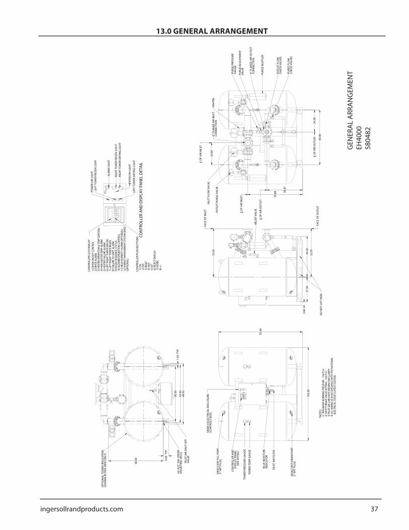
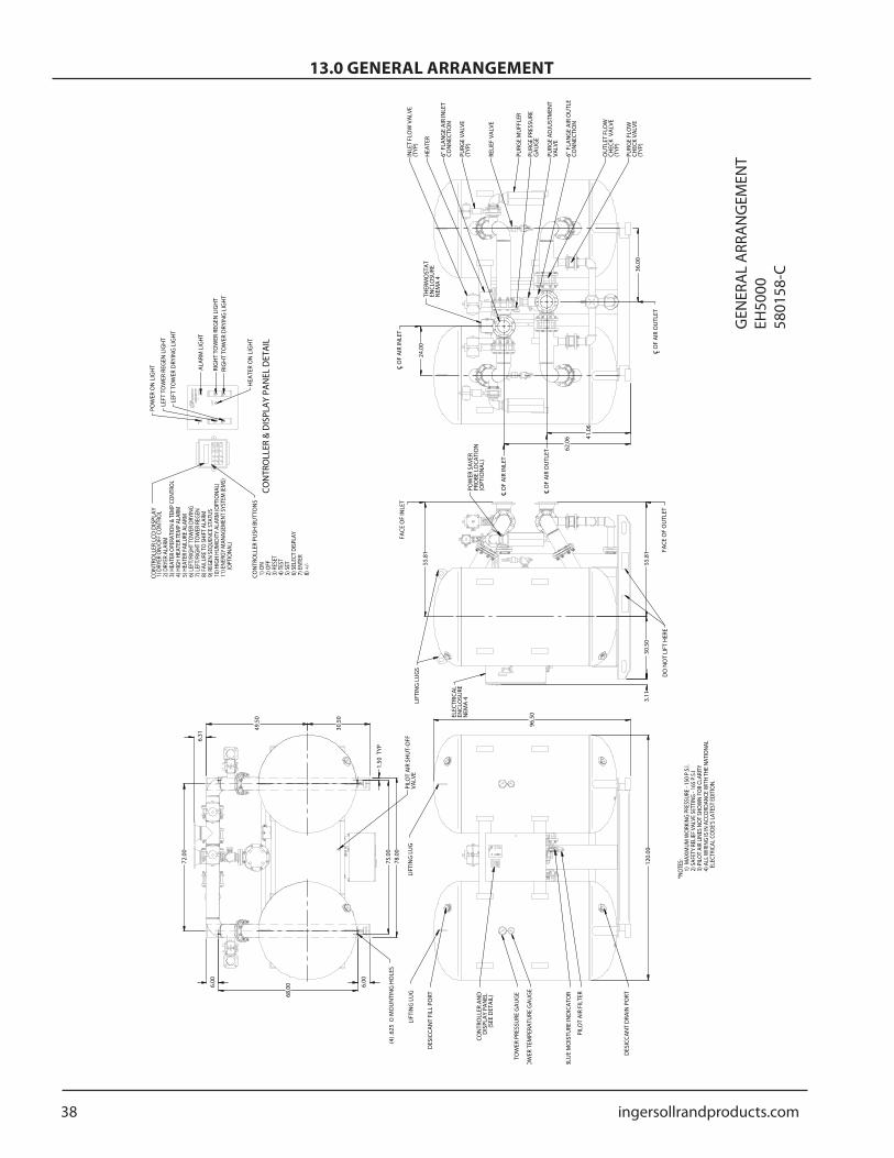
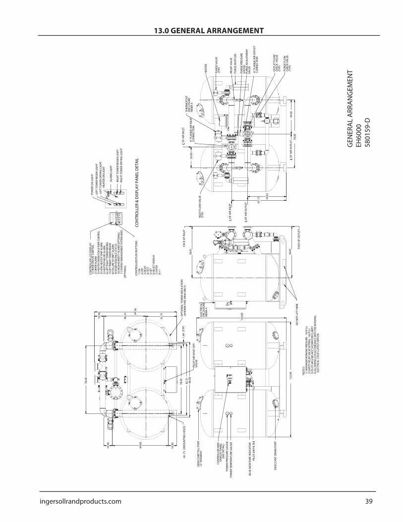
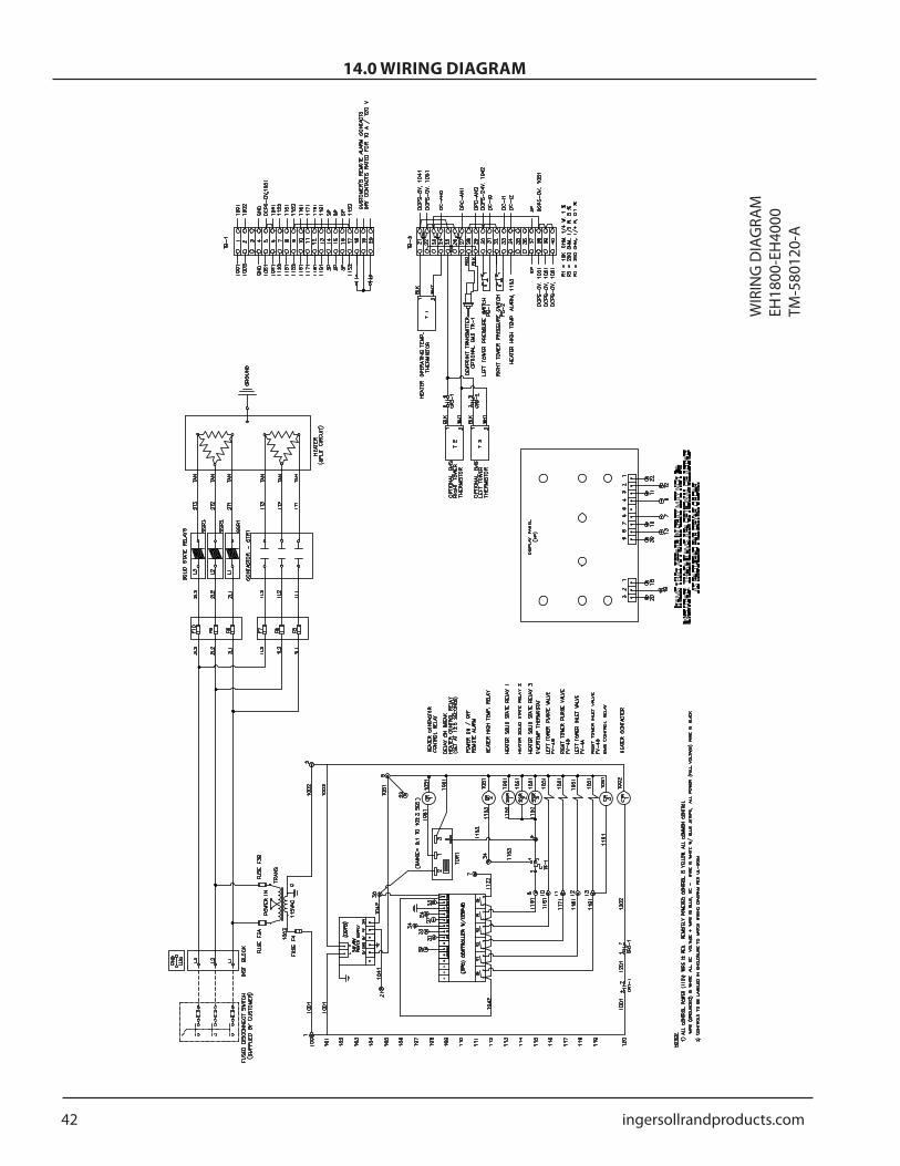
120 TROUBLESHOOTING 26130 GENERAL ARRANGEMENT 27140 WIRING DIAGRAM 41150 FLOW DIAGRAM 44160 REPLACEMENT PARTS 47170 ENGINEERING SPECIFICATIONS 51
ingersollrandproductscom 3
20 INTRODUCTION
The Company warrants that the equipment manufactured by it and delivered hereunder will be free of defects in material and workmanship for a period of twelve months from the date of placing the Equipment in operation or eighteen months from the date of shipment from the factory whichever shall first occur The Purchaser shall be obligated to promptly report any failure to conform to this warranty in writing to the Company in said period whereupon the Company shall at its option correct such nonconformity by suitable repair to such equipment or furnish a replacement part FOB point of shipment provided the Purchaser has stored installed maintained and operated such Equipment in accordance with good industry practices and has complied with specific recommendations of the Company Accessories or equipment furnished by the Company but manufactured by others shall carry whatever warranty the manufacturers have conveyed to the Company and which can be passed on to the Purchaser The Company shall not be liable for any repairs replacements or adjustments to the Equipment or any costs of labour performed by the Purchaser or others without Companyrsquos prior written approval
The effects of corrosion erosion and normal wear and tear are specifically excluded Performance warranties are limited to those specifically stated within the Companyrsquos proposal Unless responsibility for meeting such performance
warranties are limited to specified tests the Companyrsquos obligation shall be to correct in the manner and for the period of time provided above
THE COMPANY MAKES NO OTHER WARRANTY OR REPRESENTATION OF ANY KIND WHATSOEVER EXPRESSED OR IMPLIED EXCEPT THAT OF TITLE AND ALL IMPLIED WARRANTIES OF MERCHANT ABILITY AND FITNESS FOR A PARTICULAR PURPOSE ARE HERBY DISCLAIMED
Correction by the Company of non conformities whether patent or latent in the manner and for the period of time provided above shall constitute fulfilment of all liabilities of the Company for such non conformities whether based on contract warranty negligence indemnity strict liability or otherwise with respect to or arising out of such Equipment
The Purchaser shall not operate Equipment which is considered to be defective without first notifying the Company in writing of its intention to do so Any such use of Equipment will be at Purchaserrsquos sole risk and liabilityNote that this is Ingersoll Rand standard warranty Any warranty in force at the time of purchase of the equipment or negotiated as part of the purchase order may take prec-edence over this warranty
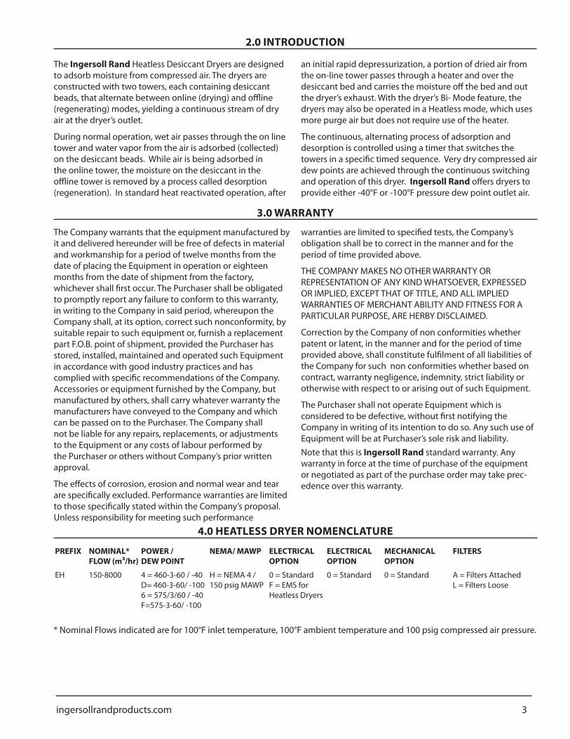
0 = Standard 0 = Standard A = Filters AttachedL = Filters Loose
Nominal Flows indicated are for 100degF inlet temperature 100degF ambient temperature and 100 psig compressed air pressure
The Ingersoll Rand Heatless Desiccant Dryers are designed to adsorb moisture from compressed air The dryers are constructed with two towers each containing desiccant beads that alternate between online (drying) and offline (regenerating) modes yielding a continuous stream of dry air at the dryerrsquos outlet
During normal operation wet air passes through the on line tower and water vapor from the air is adsorbed (collected) on the desiccant beads While air is being adsorbed in the online tower the moisture on the desiccant in the offline tower is removed by a process called desorption (regeneration) In standard heat reactivated operation after
an initial rapid depressurization a portion of dried air from the on-line tower passes through a heater and over the desiccant bed and carries the moisture off the bed and out the dryerrsquos exhaust With the dryerrsquos Bi- Mode feature the dryers may also be operated in a Heatless mode which uses more purge air but does not require use of the heater
The continuous alternating process of adsorption and desorption is controlled using a timer that switches the towers in a specific timed sequence Very dry compressed air dew points are achieved through the continuous switching and operation of this dryer Ingersoll Rand offers dryers to provide either -40degF or -100degF pressure dew point outlet air
30 WARRANTY
4 ingersollrandproductscom
Because an air dryer is pressurized and contains rotating parts the same precautions should be observed as with any piece of machinery of this type where carelessness in operation or maintenance could be hazardous to personnel In addition to obvious safety rules that should be followed with this type of machinery safety precautions as listed below must be observed
Only qualified personnel shall be permitted to adjust perform maintenance or repair this air dryer
Read all instructions completely before operating unit
Pull main electrical disconnect switch and disconnect any separate control lines if used before attempting to work or perform maintenance on the unit
Do not attempt to service any part while machine is in an operational mode
Do not attempt to remove any parts without first relieving the entire air system of pressure
Do not operate the dryer at pressures in excess of its rating
Do not operate the dryer without guards shields and screen in place
Inspect unit daily to observe and correct any unsafe operating conditions
1
2
3
4
5
6
7
8
OSHAHeading Descriptions
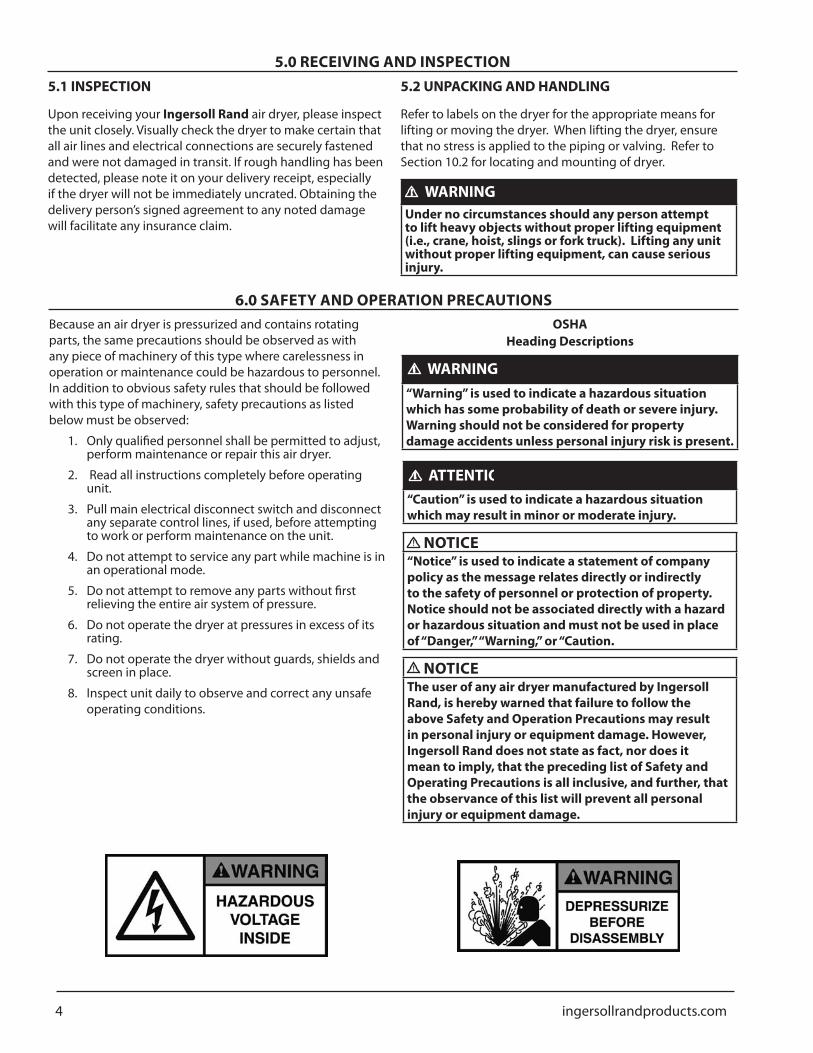
WARNINGldquoWarningrdquo is used to indicate a hazardous situation which has some probability of death or severe injury Warning should not be considered for property damage accidents unless personal injury risk is present
ATTENTIONldquoCautionrdquo is used to indicate a hazardous situation which may result in minor or moderate injury
NOTICEldquoNoticerdquo is used to indicate a statement of company policy as the message relates directly or indirectly to the safety of personnel or protection of property Notice should not be associated directly with a hazard or hazardous situation and must not be used in place of ldquoDangerrdquo ldquoWarningrdquo or ldquoCaution
NOTICEThe user of any air dryer manufactured by Ingersoll Rand is hereby warned that failure to follow the above Safety and Operation Precautions may result in personal injury or equipment damage However Ingersoll Rand does not state as fact nor does it mean to imply that the preceding list of Safety and Operating Precautions is all inclusive and further that the observance of this list will prevent all personal injury or equipment damage
60 SAFETY AND OPERATION PRECAUTIONS
50 RECEIVING AND INSPECTION51 INSPECTION
Upon receiving your Ingersoll Rand air dryer please inspect the unit closely Visually check the dryer to make certain that all air lines and electrical connections are securely fastened and were not damaged in transit If rough handling has been detected please note it on your delivery receipt especially if the dryer will not be immediately uncrated Obtaining the delivery personrsquos signed agreement to any noted damage will facilitate any insurance claim
52 UNPACKING AND HANDLING
Refer to labels on the dryer for the appropriate means for lifting or moving the dryer When lifting the dryer ensure that no stress is applied to the piping or valving Refer to Section 102 for locating and mounting of dryer
WARNINGUnder no circumstances should any person attempt to lift heavy objects without proper lifting equipment (ie crane hoist slings or fork truck) Lifting any unit without proper lifting equipment can cause serious injury
ingersollrandproductscom 5
70 PRINCIPLES OF OPERATION
71 INTRODUCTION
As described in Section 1 water vapor is removed from compressed air by diverting air flow alternately between two towers filled with activated alumina desiccant While one tower processes the compressed air stream adsorbing water vapor the opposite tower regenerates by desorbing the water vapor and venting it to atmosphere
The Microprocessor Controller provides the ability to select between heated or heatless regeneration Both heated and heatless regeneration methods are described in the following sections
NOTICEThe Microprocessor Controller must be in the OFF position prior to changing the mode (heated purge heatless) of the dryer After the change is made and the Microprocessor Control is subsequently turned ON the dryer will be in the new mode of operation
72 DRYING CYCLE
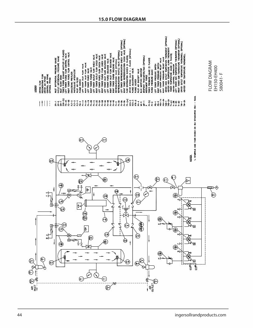
Saturated compressed air enters the dryer and is diverted to the appropriate tower by the Inlet Flow Valves (Refer to the Process and Instrumentation Diagram) The Right Tower Flow Valve is actuated to a closed position to prevent air flow from entering the regenerating tower Simultaneously the Left Tower Flow Valve is actuated to an open position allowing air flow to the drying tower During this time the Left Tower Purge Valve is actuated to a closed position preventing the compressed air from venting to atmosphere As the compressed air flows through the desiccant material in the left tower at pressure removal of water vapor from the air stream begins to occur through adsorption In the adsorption process the desiccant material draws water vapor out of the compressed air and ldquoholdsrdquo it until the left tower drying cycle is complete Compressed air flows out of the tower for delivery to the process use The Outlet Flow Check Valves provide air flow diversion to the outlet air connection of the dryer
73 REGENERATION CYCLE
Previously adsorbed moisture removed from the process stream gets stripped or desorbed from the desiccant material in the regeneration process The first stage of regeneration is tower depressurization After the Inlet Flow Valves are switched to divert air flow away from the regenerating tower the appropriate Purge Valve will be opened and the tower will be depressurized Through rapid depressurization a significant portion of the previously adsorbed water vapor is stripped off of the desiccant material and exhausted to atmosphere
CAUTIONAny time the dryer is switched between two operating modes care must be taken to ensure the purge adjustment valve is adjusted correctly Refer to the specification sheet in this manual for proper gauge setting
731 SETTING THE REGENERATION AIR FLOW
Proper setting of the purge flow is necessary to achieve proper dryer performance in the heatless and externally heated modes Setting the purge flow too high will waste compressed air and if set too low the dryer will not achieve dew point performance The purge adjustment manifold consists of the purge adjustment valve purge pressure gauge and the purge orifice The purge pressure gauge is located between the purge adjustment valve and purge orifice Manually adjust the purge adjustment valve until the reading on purge pressure gauge matches the purge pressure setting listed on the tag attached to the gauge Note that there are two purge gauge values corresponding to each mode of operation
732 HEATED PURGE REGENERATION
In the heat reactivated mode the dryer uses 75 of dry compressed air expanded to atmospheric pressure However after air expansion through the Purge Orifice the purge air is passed through the purge heater This expanded heated purge air is then passed through the regenerating tower and exhausted out to atmosphere After a three minute delay the heating process occurs for 2 hours and 57 minutes During the heating process the electric heater is cycled on and off by Ingersoll Randrsquo temperature controller Solid State relay This advanced controller precisely monitors purge air temperature and adjusts the heater temperature accordingly This results in a regeneration air temperature that remains within 15 degF from the heater setpoint for the entire regeneration cycle eliminating temperature swings associated with contactor-based heating system Upon completion of the three-hour heating period the electric heater turns off The dry regeneration air continues to flow for 57 minutes in order to cool down the desiccant bed
6 ingersollrandproductscom
70 PRINCIPLES OF OPERATION733 HEATLESS PRESSURE SWING REGENERATION
In the heatless mode following depressurization regeneration uses approximately 15 of the dry compressed air expanded to atmospheric pressure to complete the desorption process As shown on the P amp ID the compressed air exits the drying tower and a portion of the air flows through the purge adjustment valve and the Purge Orifice Once the air has passed through the Purge Orifice it expands to atmospheric pressure and continues the regeneration process Desorption occurs as the desiccant releases water vapor into the regeneration air and is exhausted through the Outlet Purge Valves
74 TOWER REPRESSURIZATION
Upon completion of tower regeneration and prior to changing the Inlet Flow Valve position to switch towers the regenerated tower must be repressurized Repressurization is accomplished by closing the appropriate purge valve Closing the Purge Valve allows the regeneration air to pressurize the tower
NOTICEFailure to repressurize prior to tower switchover will result in shocking the desiccant material and cause premature desiccant dusting
741 HEATED PURGE REPRESSURIZATION
Three minutes prior to tower switch-over repressurization is accomplished by closing the appropriate Purge Valve When the Purge Valve closes the regeneration air begins to pressurize the tower If the dryer is supplied with the optional repressurization piping the Repressurization Valve opens allowing some additional air from the outlet of the dryer to assist the purge air and to ensure adequate pressurization During normal tower regeneration the Repressurization Valve is held closed so that the only source of air for regeneration passes through the purge adjustment assembly
742 HEATLESS PRESSURE SWING REPRESSURIZATION
45 seconds prior to tower switch-over repressurization is accomplished by closing the appropriate Purge Valve When the Purge Valve closes the regeneration air begins to pressurize the tower If the dryer is supplied with the optional repressurization piping the Repressurization Valve opens allowing some additional air from the outlet of the dryer to assist the purge air and to ensure adequate pressurization During normal tower regeneration the Repressurization Valve is held closed so that the only source of air for regeneration passes through the purge adjustment assembly
75 VALVES
Flow and Purge Valves are two-way valves that are switched using airoperated double-acting actuators Each valve is actuated by a four-way solenoid valve as shown on the P amp ID
NOTICEActuated valves require 75 psi min pressure for proper operation
The Inlet Flow Valves are connected as normally open valves When the dryer is de-energized the solenoid valves for the Inlet Flow Valves supply control air to the ldquoopenrdquo port on the appropriate valve actuator
Purge Valves are connected as normally closed valves When the dryer is de-energized the solenoid valves for the Purge Valves supply control air to the ldquoclosedrdquo port on the appropriate valve actuator
Outlet Check Valves as well as Purge Check Valves are single-direction check valves that will allow flow in the direction shown on the P amp ID but not allow flow in the opposite direction
76 CONTROLS
761 MICROPROCESSOR CONTROL USER INTERFACE
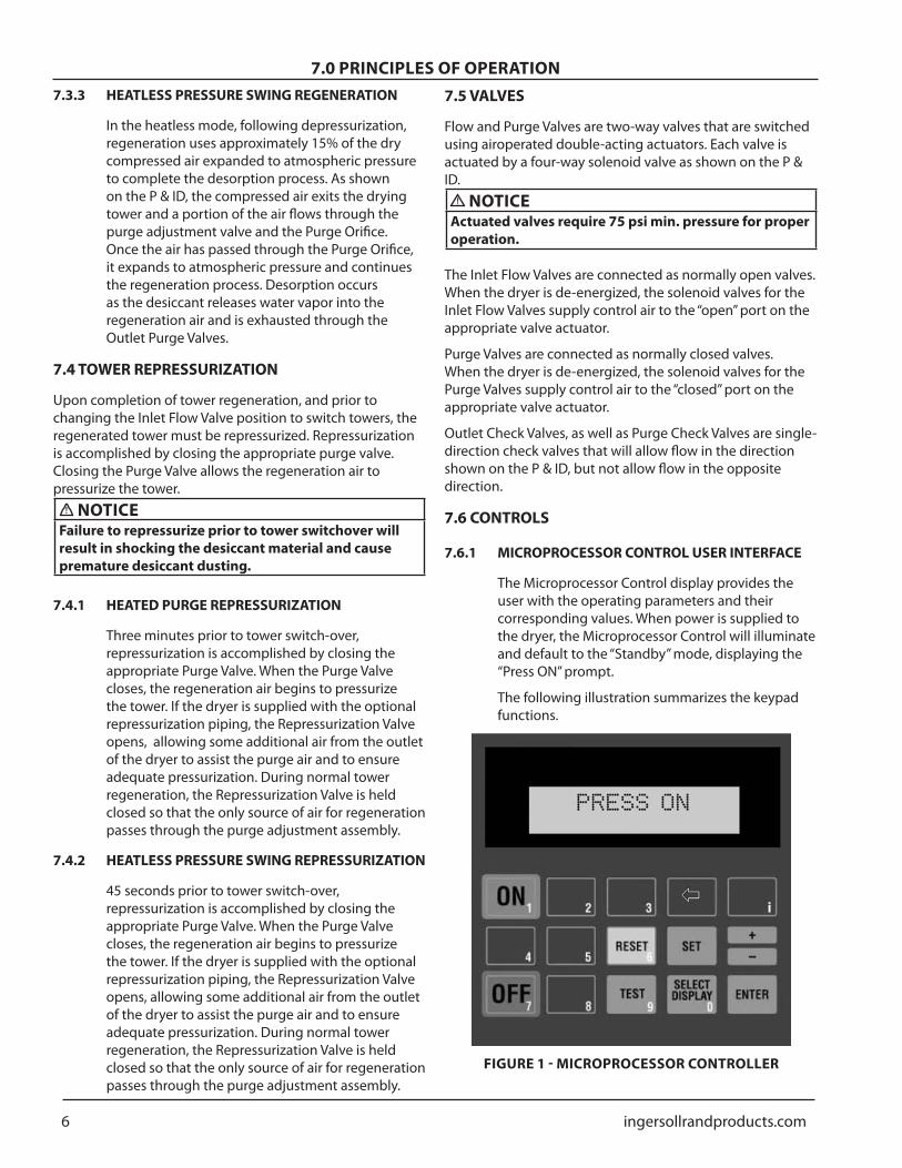
The Microprocessor Control display provides the user with the operating parameters and their corresponding values When power is supplied to the dryer the Microprocessor Control will illuminate and default to the ldquoStandbyrdquo mode displaying the ldquoPress ONrdquo prompt
The following illustration summarizes the keypad functions
FIGURE 1 - MICROPROCESSOR CONTROLLER
ingersollrandproductscom 7
70 PRINCIPLES OF OPERATION
BUTTONS
ON Initiates PLC program Begins system monitoring and valve switching functions
OFF Stops PLC program Stops valve switching functions Initiates shutdown sequence Opens Inlet Flow Valves Closes Purge Valves
SELECT DISPLAY Allows the user to scroll through the available displays The last display selected will remain displayed as the default display
+ - Allows user to modify set point values Set point values cycle through a fixed range Also allows entering negative numbers in Factory Modes
or ldquoblankrdquo button Allows user to step backwards to the previous level of the menu
bull
bull
bull
bull
bull
RESET Pressing once clears the local alarm indication and de-energizes the remote alarm contact for many alarm conditions Should the alarm condition persist the alarm will return after the alarm inhibit time has expired
SET Permits the adjustment of parameters in FACTORY MODES
ENTER Used to accept changed parameters and set point values
TEST Not used in Desiccant Dryer applications
i Restricted Level access for factory use only
762 STATUS PANEL USER INTERFACE
The status panel provides clear indication of dryer status via bright LED indicators The following illustration summarizes the panelrsquos features
bull
bull
bull
bull
bull
Secadora apagada alarma (rojo)
Regeneracioacuten de la torrederecha (amarillo)
Funcionamiento delcalefactor (verde)
Secado de la torre derecha(amarillo)
Secadora encendida(verde)
Regeneracioacuten de la torreizquierda (amarillo)
Secado de la torreizquierda (amarillo)
Figura 2 - Panel de estadoFIGURE 2 - STATUS PANEL
Dryer ON (Green)
Left Tower Regeneration (Yellow)
Left Tower Drying (Yellow)
Dryer OFF Alarm (Red)
Right Tower Regeneration (Yellow)
Right Tower Drying (Yellow)
Heater Operation (Green)
8 ingersollrandproductscom
NOTE Ingersoll Rand solid state temperature controller modulates the heater repeatedly during the heating cycle Pulsating of the heater LED will occur as a result and should be considered normal dryer operation
763 MICROPROCESSOR CONTROL DISPLAY PARAMETERS
The Microprocessor Controller is capable of displaying a number of system parameters in the default CUSTOMER MODE The following summarizes the parameters that can be accessed by depressing the SELECT DISPLAY button from the Microprocessor Controller (Note that some displays are optional and may not appear on all models)
Tower Status LT DRY RT REGEN or LT REGEN RT DRY Provides visual confirmation of tower drying and regenerating status
Step Timer ie STEP 4 TIME 120 Information screen displaying the current step in the program and the time remaining for the displayed step
Dew Point Temperature (OPTIONAL) - DEW POINT TEMP XX When equipped with the Energy Management System (EMS) feature provides accurate display of dryer outlet pressure dew point
Purge Status (OPTIONAL) - PURGE NO PURGE Indicates whether unit is currently consuming purging air Requires EMS
Heater Status (HEATED PURGE MODE ONLY) - On OFF Indicates that the heater is being given a signal to heat the purge air
Heater Temperature (HEATED PURGE MODE ONLY) - HEATER TEMP XX Indicates the heater temperature set point
Alarms ALARM LIST - PRESS ENTER Depressing ltENTgt at this prompt permits viewing of current alarm status and alarm history which includes the time and date of the alarm occurrence
Operating amp Purge Times - OPERATING TIMES - PRESS ENTER Depressing ltENTgt at this prompt provides access to the operating and purge hours of operation
Operating Mode OPERATING MODE HEATLESS HEATED PURGE EH dryers are capable of operating in Heated Purge and Heatless Pressure Swing modes This display indicates mode of operation for dryer
Once the last screen is displayed depressing the SELECT DISPLAY button will return the display to the top of the list
bull
bull
bull
bull
bull
bull
bull
bull
bull
77 TIMING SEQUENCE
All timing functions are performed by Ingersoll Randrsquo Microprocessor Controller an advanced micro PLC designed exclusively for Ingersoll Rand dryers The Microprocessor Controller is completely programmed at the factory and does not require any further adjustment The standard timing cycle switches the Inlet Flow Valve which alternates the drying tower At the same time as the Inlet Flow Valve opens the appropriate tower Purge Valve opens to begin the purge flow generation Once the purge regeneration flow portion of the dryer cycle is complete tower repressurization begins as previously described
771 HEATED PURGE TIMER CYCLE
In the externally heated operating mode the Microprocessor Control controls an eight-hour cycle The tower switch-over occurs every four hours Ten seconds after switch-over occurs the regenerating tower depressurizes for 50 seconds After depressurization heated regeneration begins and extends for 2 hours and 58 minutes The heating supply is turned off and the purge air flow continues for the next 58 minutes The purge air supply during this time is used to cool down the hot desiccant After the cool down stage a repressurization stage repressurizes the offline tower for 3 minutes
772 HEATLESS PRESSURE SWING TIMER CYCLE
In the heatless operating mode the Microprocessor Control controls a ten-minute cycle The tower switch-over occurs every five minutes Ten seconds after tower switch-over occurs the regenerating tower depressurizes and tower regeneration occurs for four minutes and 15 seconds At that time tower repressurization begins
78 RESTART MODES
The Microprocessor Controller includes a Shutdown Sequence that is activated when the dryer OFF button is depressed This feature positions the valves to their failsafe position and resets the program and is the recommended method of shutting down the dryer When the dryer is subsequently energized the dryer is ready to run at the start of the program Should however power be cut to the dryer before the Shutdown Sequence has been initiated as would be the case from a power failure the dryer can be configured to restart in one of two restart modes Note that when the dryer is shut down using the OFF button the dryer will require user intervention to restart the dryer
70 PRINCIPLES OF OPERATION
ingersollrandproductscom 9
70 PRINCIPLES OF OPERATION
781 MANUAL MODE (ZERO)
Ingersoll Rand dryers are shipped from the factory in the Manual Mode After power is re-supplied to the dryer the user will be presented with the ldquoPRESS ONrdquo display The valve switching and timing operations will only start once the ON button is depressed In this configuration to restart the dryer the user must manually depress the ON button on the Microprocessor Control panel
782 AUTO RESTART MODE (LAST)
In this mode the dryer will re-start automatically once power is applied to the dryer The Microprocessor Control will pick up where it left off in the program once power is applied
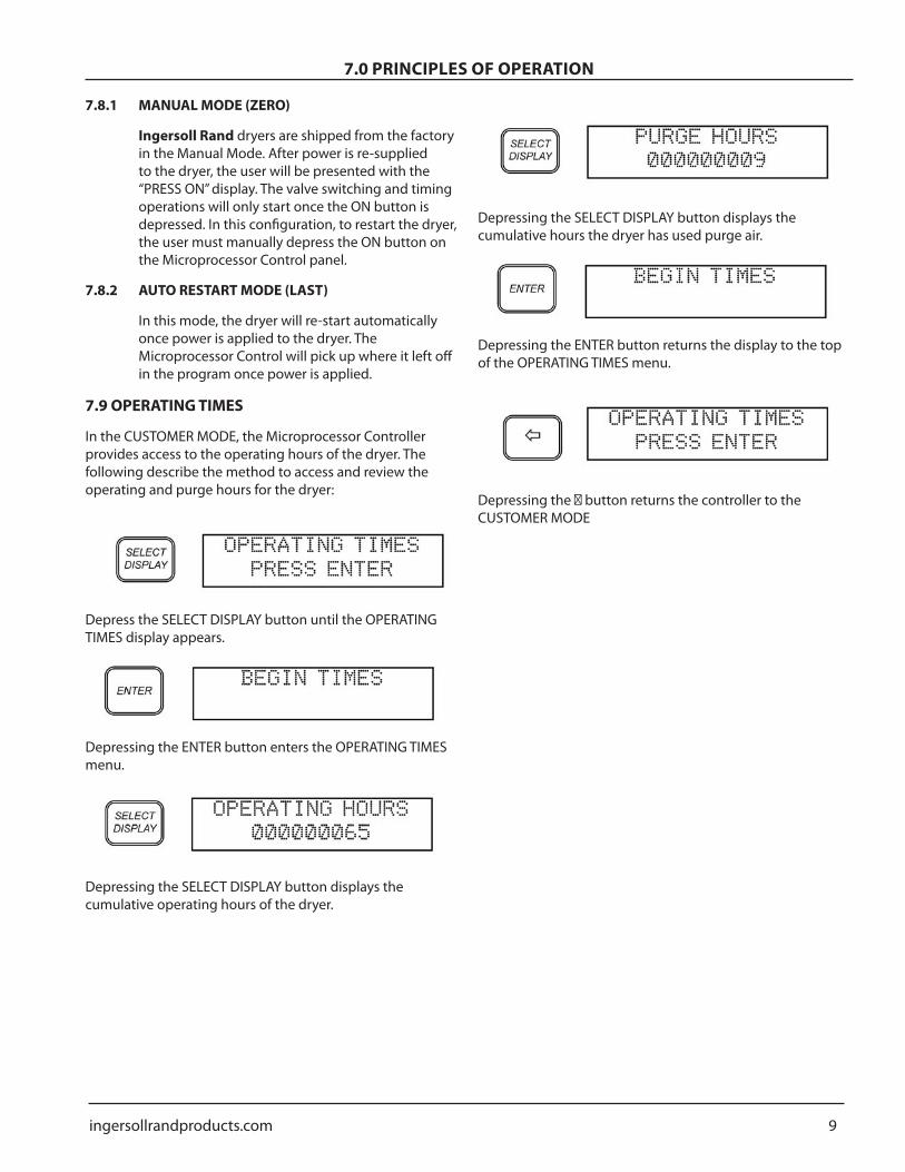
79 OPERATING TIMES
In the CUSTOMER MODE the Microprocessor Controller provides access to the operating hours of the dryer The following describe the method to access and review the operating and purge hours for the dryer
Depress the SELECT DISPLAY button until the OPERATING TIMES display appears
Depressing the ENTER button enters the OPERATING TIMES menu
Depressing the SELECT DISPLAY button displays the cumulative operating hours of the dryer
Depressing the SELECT DISPLAY button displays the cumulative hours the dryer has used purge air
Depressing the ENTER button returns the display to the top of the OPERATING TIMES menu
Depressing the 1048789 button returns the controller to theCUSTOMER MODE
10 ingersollrandproductscom
80 ALARMS AND INDICATORS
81 MOISTURE INDICATOR (STANDARD)
The moisture indicator senses a sample of the control air which is taken from the dryer outlet The indicator provides a gross indication of dew point deterioration at the outlet of the dryer Under normal operating conditions the indicator is blue In the event of a dryer malfunction or prolonged dryer shut down it will turn gray in the presence of moisture
82 HEATER HIGH TEMPERATURE ALARM WITH IN-TERLOCK (STANDARD)
The Heater High Temperature Alarm monitors the internal temperature of the heater housing Should a component failure occur or system conditions result in the heater temperature rising above the alarm set point the dryer will alarm During the alarm condition the heater is prevented from operating the Microprocessor Control halts the program at the point where the alarm occurred and displays the condition in the Microprocessor Control LCD display The dryer will be unable to be reset until the temperature of the heater has fallen below the alarm point To reinstate the dryer depress the RESET button on the Microprocessor Controller AND manually reset the Heater High Temperature Safety in the electrical enclosure Note that the alarm condition will return should proper corrective action not be taken
83 HEATER FAILURE ALARM (STANDARD)
This feature produces an alarm should the heater fail to generate heat at the beginning of the heating cycle During the initial ten minutes of the heating cycle the Microprocessor Controller monitors the heater temperature Should the heater temperature fail to rise to 150 degF within the ten minute period the Heater Failure Alarm will be triggered During this alarm condition power to the heater is removed and the program is halted Depressing the RESET button on the Microprocessor Controller will reinstate the program and provided the heater problem has been remedied continue with normal operation
84 FAILURE TO SHIFT ALARM (STANDARD)
Ingersoll Rand Failure To Shift Alarm monitors the dryer sequencing functions to insure proper dryer operation by sensing the pressure in each tower via tower pressure switches Should one of the following conditions occur the Microprocessor Controller will communicate the alarm condition There are several types of switching failure modes that can be detected by the Failure To Shift Alarm feature They are as follows
841 FAILURE TO REPRESSURIZE
At the end of the repressurization stage of the dryer operation both towers should be at line pressure Should the pressure switches indicate that both towers are not at line pressure the Failure to Shift Alarm will activate and the Microprocessor Control will stop the program at itrsquos current position in the program The user must depress the RESET button followed by the ON button at which time the Microprocessor Control will start at the beginning of the program
842 FAILURE TO DEPRESSURIZE
At the end of the depressurization stage of the dryer operation the regenerating tower should be at atmospheric pressure Should the pressure switches indicate that this is not the case the Failure to Shift Alarm will activate and the Microprocessor Control will stop the program at itrsquos current position in the program The user must depress the RESET button followed by the ON button at which time the Microprocessor Control will start at the beginning of the program
85 HIGH DEW POINT ALARM (INCLUDED WITH EMS)
The purpose of the High Dew Point Alarm is to provide the operator an alarm indication should the equipment fail to supply air at its designed pressure dew point The EMS dew point sensor communicates the pressure dew point reading to the Microprocessor Controller Should the pressure dew point rise above the alarm set point the Microprocessor Controller will display the alarm condition on the controller screen
86 ENERGY MANAGEMENT SYSTEM (EMS) (OP-TIONAL)
EMS is an energy savings feature that matches moisture loading and regeneration energy usage Drying equipment is typically operated below full flow rating andor below maximum water loading capacity of the desiccant bed The EMS option includes a dew point transmitter that transmits the outlet pressure dew point to the Microprocessor Controller The Microprocessor Controller displays the outlet pressure dew point in real-time The EMS feature utilizes the data communicated from the dew point sensor and extends the normal timed switching sequence in proportion to the moisture loading on the dryer When the EMS feature is turned off all switching sequences occur as described in Section 73 When the EMS feature is activated the drying sequence is governed by the outlet pressure dew point as
ingersollrandproductscom 11
80 ALARMS AND INDICATORSmeasured by the dew point sensor When the sampled outlet dew point registers below the customer set point (-43degF default for -40degF dryers -102degF on -100degF dryers) an immediate change in dryer operation will not be noticeable The dryer will continue its normal regeneration process through tower re-pressurization Once the tower is re-pressurized both towers will be at line pressure but air will only flow through the tower indicated by the status panel Tower switch over sequence is delayed until the dew point elevates above the EMS set point at which point tower switch over will occur
In addition to monitoring the outlet pressure dew point of the drying tower the EMS feature monitors the temperature of the purge exhaust air on the regenerating tower After a tower switch-over and at the beginning of tower regeneration the purge exhaust temperature will be relatively low (normally 90 to 110degF) The purge exhaust temperature will increase as desiccant regeneration progresses As nearly all of the previously adsorbed moisture is driven off of the desiccant the exhaust temperature will begin to rise The timing for the temperature change will vary depending on moisture loading on the towers When the purge exhaust temperature reaches 195degF which indicates that the desiccant heating is complete the Microprocessor Controller will remove power to the heater Once the heater is turned off the tower cool down process begins and continues for 57 minutes Purge air will continue to exhaust and the exhaust air temperature will continue to rise (250degF is not uncommon) as it removes the heat from the regenerated desiccant material As the cool down progresses the exhaust temperature will begin to decrease After cooling the Purge Valves close and the optional Repressurization Valve (if equipped) opens The off-line tower remains pressurized until the tower switchover sequence is initiated
87 HIGH OUTLET TEMPERATURE (OPTIONAL)
This option provides continuous monitoring of the the dryer discharge air temperature via a thermostat that senses the outlet air temperature during dryer operation Should a high outlet temperature condition exist the alarm is displayed on the Microprocessor Controller to alert maintenance personnel of a malfunction This alarm does not interrupt the dryer program Depressing the RESET button will clear the alarm provided the alarm condition as been addressed Note that the alarm will clear automatically once the high temperature condition is corrected
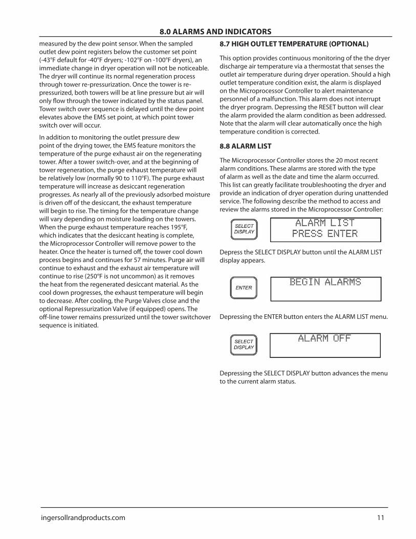
88 ALARM LIST
The Microprocessor Controller stores the 20 most recent alarm conditions These alarms are stored with the type of alarm as well as the date and time the alarm occurred This list can greatly facilitate troubleshooting the dryer and provide an indication of dryer operation during unattended service The following describe the method to access and review the alarms stored in the Microprocessor Controller
Depress the SELECT DISPLAY button until the ALARM LIST display appears
Depressing the ENTER button enters the ALARM LIST menu
Depressing the SELECT DISPLAY button advances the menu to the current alarm status
12 ingersollrandproductscom
80 ALARMS AND INDICATORS
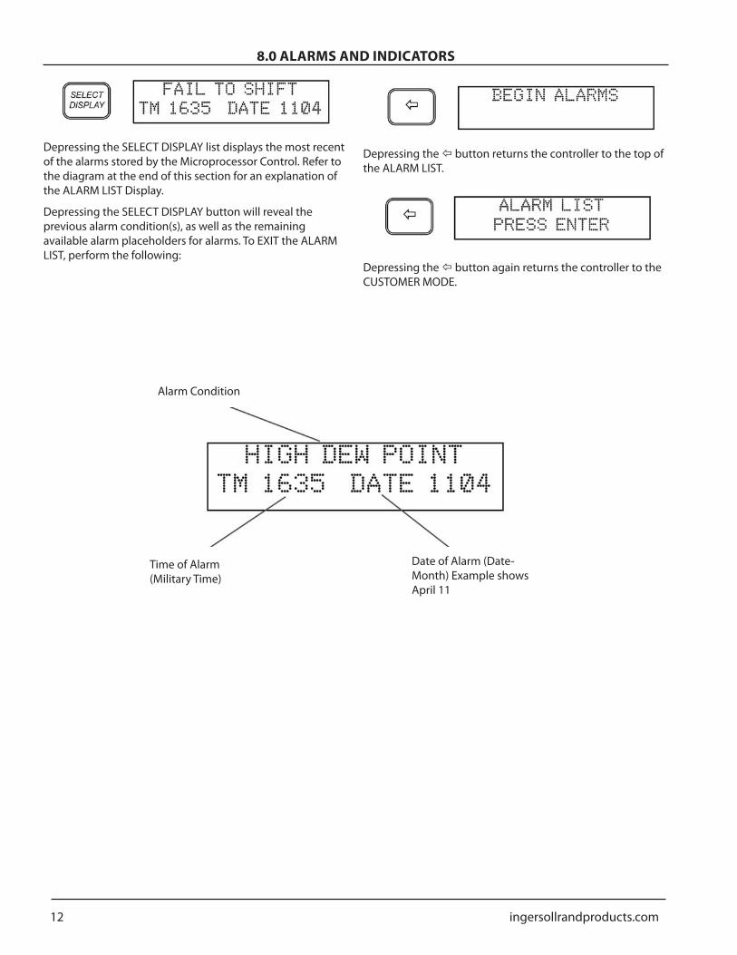
Depressing the SELECT DISPLAY list displays the most recent of the alarms stored by the Microprocessor Control Refer to the diagram at the end of this section for an explanation of the ALARM LIST Display
Depressing the SELECT DISPLAY button will reveal the previous alarm condition(s) as well as the remaining available alarm placeholders for alarms To EXIT the ALARM LIST perform the following
Depressing the button returns the controller to the top of the ALARM LIST
Depressing the button again returns the controller to the CUSTOMER MODE
Alarm Condition
Time of Alarm (Military Time)
Date of Alarm (Date-Month) Example shows April 11
ingersollrandproductscom 13
90 TECHNICIAN MODEThe Microprocessor Control provides a protected TECHNICIAN MODE to manipulate several parameters not accessible by the casual operator Below is a list of parameters that can be accessed and manipulated by the technician in the TECHNICIAN MODE
Parameter Display Set PointOPERATION MODE OPERATION
MODEHTLS HEATED
ENERGY MANAGEMENTSYSTEM (OPTIONAL)
EMS OFF ON
ENERGY MANAGEMENT SYSTEMSETPOINT (OPTIONAL)
EMS SET POINT -76 - +68
PURGE TEMPERATURE PURGE TEMP OFF ON
RESTART MODE RESTART LAST ZERO
EXTENDED HEATING EXTENDED HTG OFF ON
HIGH DEW POINT ALARMACTIVATION (OPTIONAL)
HIGH DEWPOINT
OFF ON
NOTE Setpoints indicated are adjustable ONLY when dryer is equipped with the Energy Management System option Setpoints are non-adjustable on dryers
91 ENTERING TECHNICIAN MODE
WARNINGTECHNICIAN MODE should only be entered by qualified service personnel Altering the set points in TECHNICIAN MODE will have a significant effect on the operation of the dryer Incorrect set points may damage dryer and cause potential serious injury
To enter the TECHNICIAN MODE perform the following keystrokes
Pressing the ldquo2rdquo and ldquo3rdquo buttons simultaneously enters the TECHNICIAN MODE
Depressing SELECT DISPLAY scrolls through the available parameters
92 OPERATING MODE (BI-MODE)
As described in Section 7 Heat Reactivated Dryers can operate in a heated purge mode as well as a heatless pressure swing mode To change the operation mode of the dryer perform the following keystrokes
Depress the SELECT DISPLAY button until the SET OPERATION MODE screen is displayed
Depress the +- button until the desired dew point is displayed Pressing SELECT DISPLAY saves the current selection
NOTICEThe Microprocessor Controller must be in the OFF position prior to changing the mode (heated purge heatless) of the dryer After the change is made and the Microprocessor Control is subsequently turned ON the dryer will be in the new mode of operation
CAUTIONAny time the dryer is switched between two operating modes care must be taken to ensure the purge adjustment valve is adjusted correctly Refer to the specification sheet in this manual for proper gauge setting
93 HEATER TEMPERATURE SETPOINT (HEATED PURGE MODE ONLY)
The Microprocessor Controller permits the user to adjust the temperature of the heater thereby altering the regeneration temperature in the heated purge mode
WARNINGThe user is advised to only alter the regeneration temperature after being instructed to do so by Ingersoll Rand factory personnel Improper or inappropriate manipulation of the heater temperature can result in degraded dryer performance equipment damage and serious injury Notify Ingersoll Rand Compressed Air Solutions prior to altering the heater temperature
14 ingersollrandproductscom
90 TECHNICIAN MODE
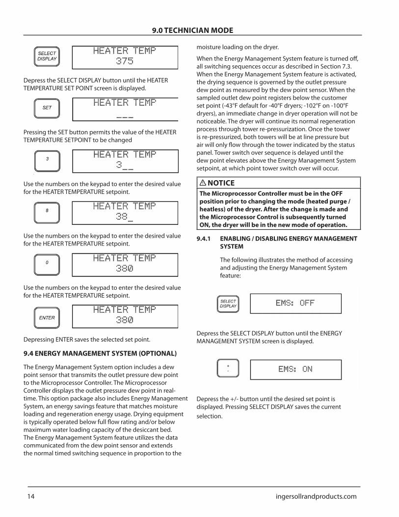
Depress the SELECT DISPLAY button until the HEATER TEMPERATURE SET POINT screen is displayed
Pressing the SET button permits the value of the HEATER TEMPERATURE SETPOINT to be changed
t
Use the numbers on the keypad to enter the desired value for the HEATER TEMPERATURE setpoint
Use the numbers on the keypad to enter the desired value for the HEATER TEMPERATURE setpoint
Use the numbers on the keypad to enter the desired value for the HEATER TEMPERATURE setpoint
Depressing ENTER saves the selected set point
94 ENERGY MANAGEMENT SYSTEM (OPTIONAL)
The Energy Management System option includes a dew point sensor that transmits the outlet pressure dew point to the Microprocessor Controller The Microprocessor Controller displays the outlet pressure dew point in real-time This option package also includes Energy Management System an energy savings feature that matches moisture loading and regeneration energy usage Drying equipment is typically operated below full flow rating andor below maximum water loading capacity of the desiccant bed The Energy Management System feature utilizes the data communicated from the dew point sensor and extends the normal timed switching sequence in proportion to the
moisture loading on the dryer
When the Energy Management System feature is turned off all switching sequences occur as described in Section 73 When the Energy Management System feature is activated the drying sequence is governed by the outlet pressure dew point as measured by the dew point sensor When the sampled outlet dew point registers below the customer set point (-43degF default for -40degF dryers -102degF on -100degF dryers) an immediate change in dryer operation will not be noticeable The dryer will continue its normal regeneration process through tower re-pressurization Once the tower is re-pressurized both towers will be at line pressure but air will only flow through the tower indicated by the status panel Tower switch over sequence is delayed until the dew point elevates above the Energy Management System setpoint at which point tower switch over will occur
NOTICEThe Microprocessor Controller must be in the OFF position prior to changing the mode (heated purge heatless) of the dryer After the change is made and the Microprocessor Control is subsequently turned ON the dryer will be in the new mode of operation
941 ENABLING DISABLING ENERGY MANAGEMENT SYSTEM
The following illustrates the method of accessing and adjusting the Energy Management System feature
Depress the SELECT DISPLAY button until the ENERGY MANAGEMENT SYSTEM screen is displayed
Depress the +- button until the desired set point is displayed Pressing SELECT DISPLAY saves the current selection
ingersollrandproductscom 15
90 TECHNICIAN MODE
942 SETPOINT ADJUSTMENTOn dryers equipped with the optional Energy Management System the setpoint can be adjusted to match the dryers operation to the desired pressure dew point
The following illustrates the method of adjusting the setpoint for the Energy Management System feature
Depress the SELECT DISPLAY button until the EMS SET POINT screen is displayed
Pressing the SET button permits the value of the EMS SETPOINT to be changed
To enter a negative number depress the +- button Otherwise proceed to the next step
Use the numbers on the keypad to enter the desired pressure dew point temperature for the EMS setpoint
Use the numbers on the keypad to enter the desired pressure dew point temperature for the EMS setpoint
Depressing ENTER saves the selected set point
95 PURGE TEMPERATURE (OPTIONAL HEATED PURGE MODE)
On dryers equipped with EMS the temperature of the purge exhaust is monitored and displayed on the Microprocessor Controller After a tower switch-over and at the beginning of tower regeneration the purge exhaust temperature will be relatively low (normally 90 to 110degF) The purge exhaust temperature will increase as desiccant regeneration progresses As nearly all of the previously adsorbed moisture is driven off of the desiccant the exhaust temperature will begin to rise The timing for the temperature change will vary depending on moisture loading on the towers When the purge exhaust temperature reaches 195degF which indicates that the desiccant heating is complete the Microprocessor Controller will remove power to the heater Once the heater is turned off the tower cool down process begins and continues for 57 minutes Purge air will continue to exhaust and the exhaust air temperature will continue to rise (250degF is not uncommon) as it removes the heat from the regenerated desiccant material As the cool down progresses the exhaust temperature will begin to decrease After cooling the Purge Valves close and the optional Repressurization Valve (if equipped) opens The off-line tower remains pressurized until the tower switchover sequence is initiated Activation of the Purge Temperature feature is via the Microprocessor Controller
The following illustrates the method of accessing and activating the Purge Temperature feature
Depress the SELECT DISPLAY button until the PURGE TEMP screen is displayed
Depress the +- button until the desired set point is displayed Pressing SELECT DISPLAY saves the current selection
96 RESTART MODE
Ingersoll Rand dryers can be configured to restart in one of two operating modes As described in Section 78 the dryer may be configured for Manual operation (factory default) or Auto Restart which permits the dryer to operate automatically once power is re-applied to the dryer after a power failure The following illustrates the method of accessing and adjusting the different start modes for the dryer
16 ingersollrandproductscom
90 TECHNICIAN MODE
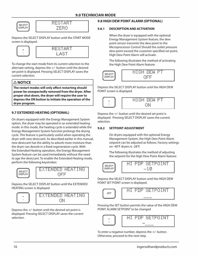
Depress the SELECT DISPLAY button until the START MODE screen is displayed
To change the start mode from its current selection to the alternate setting depress the +- button until the desired set point is displayed Pressing SELECT DISPLAY saves the current selection
NOTICEThe restart modes will only affect restarting should power be unexpectedly removed from the dryer After proper shut down the dryer will require the user to depress the ON button to initiate the operation of the dryer program
97 EXTENDED HEATING (OPTIONAL)
On dryers equipped with the Energy Management System option the dryer may be operated in an extended heating mode In this mode the heating cycle is extended while the Energy Management System function prolongs the drying cycle This feature is particularly useful when operating the dryer with new desiccant As described earlier in this manual new desiccant has the ability to adsorb more moisture than the dryer can desorb in a fixed regeneration cycle With the Extended Heating operation the Energy Management System feature can be used immediately without the need to age the desiccant To enable the Extended Heating mode perform the following keystrokes
Depress the SELECT DISPLAY button until the EXTENDED HEATING screen is displayed
Depress the +- button until the desired set point is displayed Pressing SELECT DISPLAY saves the current selection
98 HIGH DEW POINT ALARM (OPTIONAL)
981 DESCRIPTION AND ACTIVATION
When the dryer is equipped with the optional Energy Management System feature the dew point sensor transmits the dew point to the Microprocessor Control Should the outlet pressure dew point exceed the customer specified set point High Dew Point Alarm will activate
The following illustrates the method of activating the High Dew Point Alarm feature
Depress the SELECT DISPLAY button until the HIGH DEW POINT screen is displayed
Depress the +- button until the desired set point is displayed Pressing SELECT DISPLAY saves the current selection
982 SETPOINT ADJUSTMENT
On dryers equipped with the optional Energy Management System the High Dew Point Alarm setpoint can be adjusted as follows Factory settings on -40degF dryers is -28degF
The following illustrates the method of adjusting the setpoint for the High Dew Point Alarm feature
Depress the SELECT DISPLAY button until the HIGH DEW POINT SET POINT screen is displayed
Pressing the SET button permits the value of the HIGH DEW POINT ALARM SETPOINT to be changed
To enter a negative number depress the +- button Otherwise proceed to the next step
ingersollrandproductscom 17
90 TECHNICIAN MODE
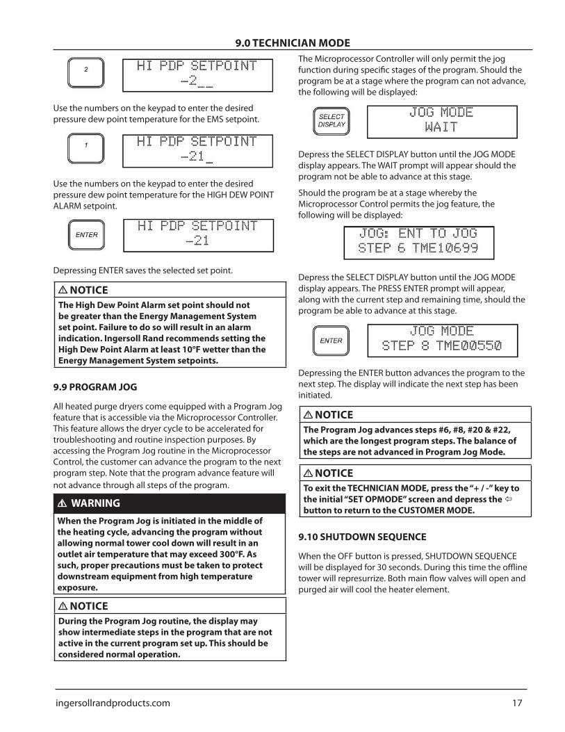
Use the numbers on the keypad to enter the desired pressure dew point temperature for the EMS setpoint
Use the numbers on the keypad to enter the desired pressure dew point temperature for the HIGH DEW POINT ALARM setpoint
Depressing ENTER saves the selected set point
NOTICEThe High Dew Point Alarm set point should not be greater than the Energy Management System set point Failure to do so will result in an alarm indication Ingersoll Rand recommends setting the High Dew Point Alarm at least 10degF wetter than the Energy Management System setpoints
99 PROGRAM JOG
All heated purge dryers come equipped with a Program Jog feature that is accessible via the Microprocessor Controller This feature allows the dryer cycle to be accelerated for troubleshooting and routine inspection purposes By accessing the Program Jog routine in the Microprocessor Control the customer can advance the program to the next program step Note that the program advance feature will not advance through all steps of the program
WARNINGWhen the Program Jog is initiated in the middle of the heating cycle advancing the program without allowing normal tower cool down will result in an outlet air temperature that may exceed 300degF As such proper precautions must be taken to protect downstream equipment from high temperature exposure
NOTICEDuring the Program Jog routine the display may show intermediate steps in the program that are not active in the current program set up This should be considered normal operation
The Microprocessor Controller will only permit the jog function during specific stages of the program Should the program be at a stage where the program can not advance the following will be displayed
Depress the SELECT DISPLAY button until the JOG MODE display appears The WAIT prompt will appear should the program not be able to advance at this stage
Should the program be at a stage whereby the Microprocessor Control permits the jog feature the following will be displayed
Depress the SELECT DISPLAY button until the JOG MODE display appears The PRESS ENTER prompt will appear along with the current step and remaining time should the program be able to advance at this stage
Depressing the ENTER button advances the program to the next step The display will indicate the next step has been initiated
NOTICEThe Program Jog advances steps 6 8 20 amp 22 which are the longest program steps The balance of the steps are not advanced in Program Jog Mode
NOTICETo exit the TECHNICIAN MODE press the ldquo+ -rdquo key to the initial ldquoSET OPMODErdquo screen and depress the button to return to the CUSTOMER MODE
910 SHUTDOWN SEQUENCE
When the OFF button is pressed SHUTDOWN SEQUENCE will be displayed for 30 seconds During this time the offline tower will represurrize Both main flow valves will open and purged air will cool the heater element
18 ingersollrandproductscom
100 INSTALLATION AND INITIAL START-UP
101 EQUIPMENT APPLICATION GUIDELINES
Ingersoll Rand Regenerative air dryers are shipped complete with desiccant up to and including model EH2100 On larger units the desiccant is packaged separately for ease in handling Refer to Section 96 for desiccant fill procedures
To achieve the best dryer performance carefully check that the design and installation requirements outlined below are satisfied
Ingersoll Rand dryers are available with an operating range from 75 - 150 PSIG Air available for your usage will vary with operating pressure The maximum design pressure of the standard Desiccant Dryers is 150 PSIG For units that require higher operating pressures consult your Ingersoll Rand representative
Dryers are sized according to flow and pressure drop not pipe size The difference between the inlet and the outlet flow is the amount of purge air required This air is exhausted to atmosphere and is not available for use downstream Make certain air supply to dryer meets air demand plus purge air requirements
NOTICEThe standard dryer is not rated for any gas other than air
NOTICEIngersoll Rand recommends that the mufflers be cleaned after initial start-up to remove any desiccant dust generated during shipment After running dryer for initial 30 minute period de-energize depressurize dryer and remove mufflers Disassemble and clean the removable insert inside the muffler core Reinstall mufflers prior to operating dryer
102 LOCATING AND MOUNTING
The dryer must never be installed where air andor ambient temperature exceeds 120degF or drops below +35degF Locate dryer to avoid extremes of heat and cold from ambient or other conditions Where applicable dryer towers may be insulated to reduce heat loses Avoid locating dryer outside or where it is exposed to the elements
The dryer or any air system component must be located to avoid exposure to pulsation in the compressed air as well as possible surges due to fluctuating demand In addition care must be used to minimize exposure to vibration transmitted through mounting pads or piping
Provide adequate space around the dryer for normal maintenance requirements and service
If the dryer is shipped with the desiccant packaged separately install the desiccant after locating and mounting
Desiccant has been provided separately to minimize handling difficulty and placing unnecessary stress on the dryer assembly
Bolt the dryer to the foundation using the bolt holes provided in the base frame Anchor bolts should project a minimum of 35 inches above the foundation and allow proper nut and washer assembly
103 PIPING
Pipe the compressed air lines to the inlet and outlet connections Locate the pre-filters as close as possible to the dryer Ensure the positioning allows for ease of servicing
Note that the wet air inlet is at the dryerrsquos lower manifold while the dry air outlet is at the dryerrsquos upper manifold In situations where air supply is required 24 hours a day (it is undesirable to interrupt the airflow) a three valve by-pass system is recommended to bypass the dryer To keep pressure drop at a minimum use the fewest elbows necessary
To eliminate noise created by frequent tower release of purge exhaust the dryerrsquos exhaust may be piped to an outside or more remote location This will also eliminate any possible problems caused by indoor accumulation of condensed moisture from the purge exhaust If extending the exhaust pipe install it horizontal or downward to avoid accumulation of condensate at low points If the purge exhaust is required to run upward install a valve at the low point Keep this valve partially (50-75) open to continually drain any liquid water If extending the exhaust pipe farther than 15 feet consult the factory for recommendations
Once all piping has been connected all joints including those on the dryer should be soap bubble tested at line pressure to ensure no joints have been damaged in transit and site placement
104 FILTRATION
It is important that a pre-filter and an post-filter be provided in your dryer installation These are included with the dryer They are mounted on models EH1500 and below
NOTICEAll dryers must have proper filtration Liquid water and oil must be removed before the air enters the dryer Ensure separators pre-filters and drains are in good working order Failure to do so will void warranty
It is recommended that a mechanical separator be installed immediately preceding the pre-filter to remove the bulk liquid and entrained water
ingersollrandproductscom 19
100 INSTALLATION AND INITIAL START-UP
Coalescing pre-filters located before the dryer protect desiccant beds from contamination by oil entrained water pipe scale etc thereby extending dryer desiccant life Locate pre-filters as close to dryer as possible FAILURE TO PROVIDE AND MAINTAIN A HIGH EFFICIENCY COALESCING PRE-FILTER WILL VOID DRYER WARRANTY
Post-filters located after the dryer help eliminate the possibility of desiccant dusting carrying over into the air system
WARNINGHigh temperature filters must be used to prevent rupture possibility in the event dryer failure should occur Consult your Ingersoll Rand representative for appropriate filter selection
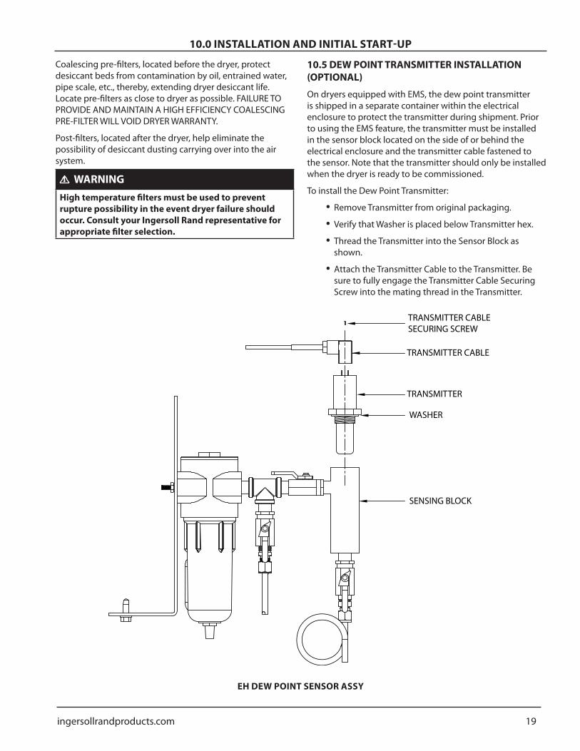
105 DEW POINT TRANSMITTER INSTALLATION (OPTIONAL)
On dryers equipped with EMS the dew point transmitter is shipped in a separate container within the electrical enclosure to protect the transmitter during shipment Prior to using the EMS feature the transmitter must be installed in the sensor block located on the side of or behind the electrical enclosure and the transmitter cable fastened to the sensor Note that the transmitter should only be installed when the dryer is ready to be commissioned
To install the Dew Point Transmitter
Remove Transmitter from original packaging
Verify that Washer is placed below Transmitter hex
Thread the Transmitter into the Sensor Block as shown
Attach the Transmitter Cable to the Transmitter Be sure to fully engage the Transmitter Cable Securing Screw into the mating thread in the Transmitter
bullbullbull
bull
TRANSMITTER CABLE SECURING SCREW
TRANSMITTER CABLE
TRANSMITTER
WASHER
SENSING BLOCK
EH DEW POINT SENSOR ASSY
20 ingersollrandproductscom
100 INSTALLATION AND INITIAL START-UP
106 ELECTRICAL CONNECTION
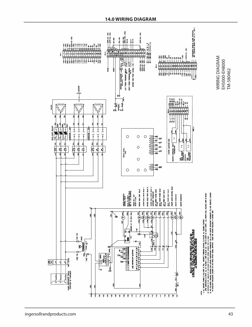
Refer to wiring diagram for all electrical connections Electrical connection must be hard piped with an external fused disconnect switch with proper overload protection
Size field connection knock-out for the conduit fitting required by the NEC
Service wires must be sized according to the minimum circuit ampacity shown on the dryer serial nameplate and the requirements of the NEC
The power connections are marked L1 L2 and L3
CAUTIONDryer must be grounded with the full sized ground wire connected to an earth ground
107 START-UP
NOTICEInitial dryer start-up must be in the Heated Purge Mode
With dryer de-energized slowly pressurize the dryer When the dryer reaches full operating pressure check the system for air leaks Soap test all joints and fitting To maintain desired dew point any leaks detected must be repaired especially those on the outlet side of the dryer
Turn on dryer disconnect switch to apply power to the dryer
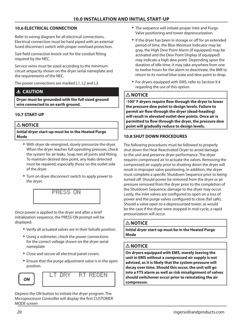
Once power is applied to the dryer and after a brief initialization sequence the PRESS ON prompt will be displayed
Verify all actuated valves are in their failsafe position
Using a voltmeter check the power connections for the correct voltage shown on the dryer serial nameplate
Close and secure all electrical panel covers
Ensure that the purge adjustment valve is in the open position
Depress the ON button to initiate the dryer program The Microprocessor Controller will display the first CUSTOMER MODE screen
bull
bull
bullbull
bullbull
The sequence will initiate proper Inlet and Purge Valve positioning and tower depressurization
If the dryer has been in storage or off for an extended period of time the Blue Moisture Indicator may be gray the High Dew Point Alarm (if equipped) may be activated and the Dew Point Display (if equipped) may indicate a high dew point Depending upon the duration of idle time it may take anywhere from one to twelve hours for the alarm to deactivate the BMI to return to its normal blue state and dew point to drop
For dryers equipped with EMS refer to Section 94 regarding the use of this option
NOTICE-100deg F dryers require flow through the dryer to lower the pressure dew point to design levels Failure to permit air flow through the dryer (dead-heading) will result in elevated outlet dew points Once air is permitted to flow through the dryer the pressure dew point will gradually reduce to design levels
108 SHUT DOWN PROCEDURES
The following procedures must be followed to properly shut down the Heat Reactivated Dryer to avoid damage to the unit and preserve dryer performance The dryer requires compressed air to actuate the valves Removing the compressed air supply prior to shutting down the dryer will result in improper valve positioning In addition the dryer must complete a specific Shutdown Sequence prior to being turned off Should power be removed from the dryer or air pressure removed from the dryer prior to the completion of the Shutdown Sequence damage to the dryer may occur Lastly the inlet valves are configured to open on a loss of power and the purge valves configured to close (fail safe) Should a valve open to a depressurized tower as would be the case if the dryer were stopped in mid-cycle a rapid pressurization will occur
NOTICEInitial dryer start-up must be in the Heated Purge Mode
NOTICEOn dryers equipped with EMS merely leaving the unit in EMS without a compressed air supply is not advised as it is likely that the system pressure will decay over time Should this occur the unit will go into a FTS alarm as well as risk misalignment of valves should switchover occur prior to reinstating the air compressor
bull
bull
bull
ingersollrandproductscom 21
100 INSTALLATION AND INITIAL START-UP
CAUTIONDryer should not be shut down during the heating cycle Doing so may cause the Heater High Temperature alarm to activate which will require the user to manually reset the Heater High Temperature safety in the control enclosure If the dryer must be shut down during the heating cycle advance the program via the Program Jog function (see Section 99) to the end of the heating cycle prior to initiating the Shutdown Sequence
For all Heat Reactivated Dryers Ingersoll Rand recommends that an isolation valve be installed at the dryer outlet Upon restarting the dryer it is likely that the pressure downstream of the dryer will have decayed When starting the dryer without the valve (or with the valve in the fully open position) the high velocities of the air through the towers could damage the desiccant as well as provide unprocessed air down stream
NOTICEPrior to removing power or compressed air from the dryer depress the OFF button on the Microprocessor Control This initiates the Shutdown Sequence which closes the purge valves repressurizes the off-line tower and opens the flow valves DO NOT REMOVE POWER OR COMPRESSED AIR FROM THE DRYER DURING THE SHUTDOWN SEQUENCE
Shut Down Procedure
Maintain a compressed air source to the dryer and a supply of power to the Microprocessor Controller
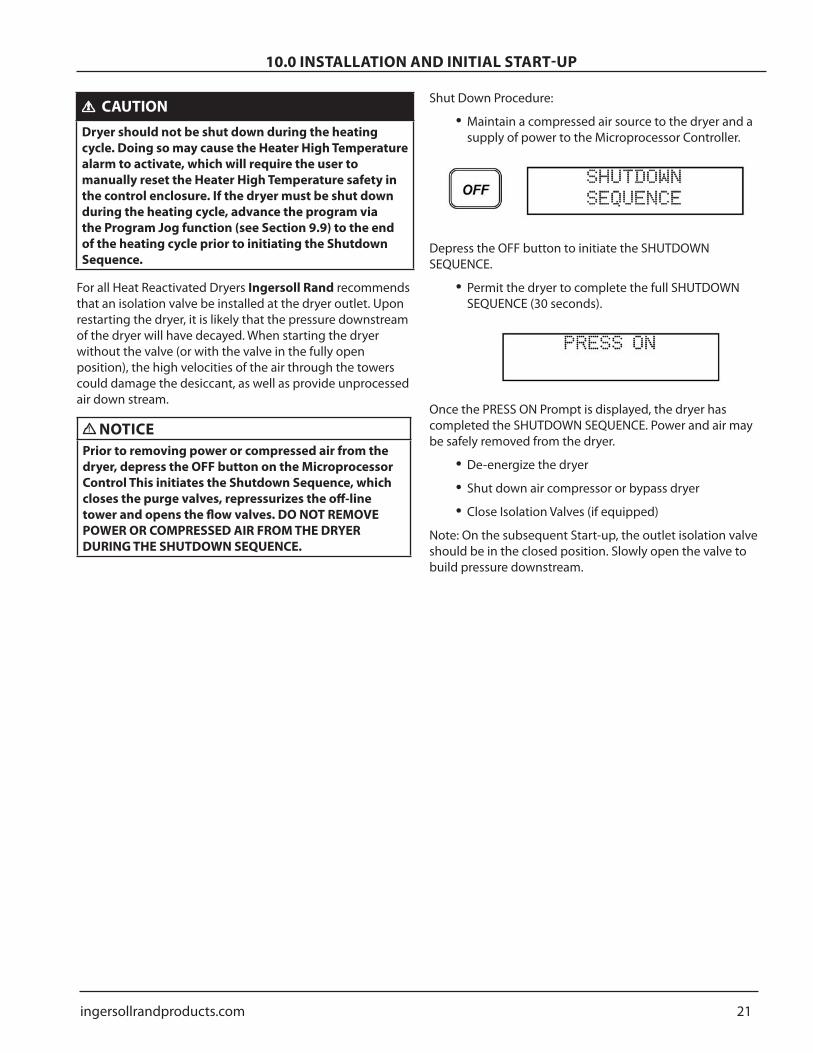
Depress the OFF button to initiate the SHUTDOWN SEQUENCE
Permit the dryer to complete the full SHUTDOWN SEQUENCE (30 seconds)
Once the PRESS ON Prompt is displayed the dryer has completed the SHUTDOWN SEQUENCE Power and air may be safely removed from the dryer
De-energize the dryer
Shut down air compressor or bypass dryer
Close Isolation Valves (if equipped)
Note On the subsequent Start-up the outlet isolation valve should be in the closed position Slowly open the valve to build pressure downstream
bull
bull
bullbullbull
22 ingersollrandproductscom
110 MAINTENANCE AND SYSTEM CHECK
111 SCHEDULED MAINTENANCE
DAILY MAINTENANCE FUNCTIONS
Check and record inlet pressure temperature and flow Verify that it is within specifications
Check tower pressure gauge readings within operating tolerance
Check tower pressure gauges for proper dryer cycling
Check that pre-filter condensate drains are functioning properly Replace cartridges sooner if necessary as required by differential pressure indicator
Verify that pressure in purging tower is 5 PSIG or less
Verify that pre-filter and post-filter differential pressure is within operating limits Replace cartridges sooner if necessary as required by differential pressure indicator
MONTHLY MAINTENANCE FUNCTIONS
Check your operating conditions inlet flow inlet pressure and inlet temperature
Check pre-filter(s) and post-filter(s) differential pressure and drains Replace cartridges sooner if necessary as required by differential pressure indicator
Check dryer cycle and sequence of operations (ie drying depressurizing regenerating)
QUARTERLY MAINTENANCE FUNCTIONS
Replace pre-filter(s) and post-filter(s) cartridges Replace cartridges sooner if necessary as required by differential pressure indicator
Check pilot air filter element and replace as needed
SEMI-ANNUAL MAINTENANCE FUNCTIONS
Check outlet dew point
Check amp draw on heater
Replace pre-filter and post-filter elements and or cartridges Replace cartridges sooner if necessary as required by differential pressure indicator
ANNUAL MAINTENANCE FUNCTIONS
Check desiccant and replace if necessary
Inspect and clean no-loss drain valves and check valves Replace worn or damaged seats and parts as required
Test lights and switches replace as necessary
Test electrical components replace as necessary
bull
bull
bullbull
bullbull
bull
bull
bull
bull
bull
bullbullbull
bullbull
bullbull
Check and repair any air leaks loose bolts flanges and fittings
EVERY TWO YEARS
Change check valves
Change control no-loss drain valves
Check and change temperature probes
EVERY THREE - TO - FIVE YEARS
Replace desiccant
NOTICERefer to Section 107 for the proper way to shut down the Heat Reactivated Dryer
112 PRE-FILTERS AND POST-FILTERS
Pre-filter elements must be changed as often as required to prevent contamination of the regenerative dryerrsquos desiccant bed
Pre-filter drains must be checked daily Failure to drain condensed liquid from the sump of the filter housing will result in carry over and damage to the desiccant material HB post-filters are used to prevent desiccant dust particulate contamination from migrating downstream into plant processes Elements should be changed as pressure drop increases to an undesirable level
NOTICEShould the drying system be overloaded andor malfunctioning causing high pressure drop HB post-filters will prematurely plug This problem can be avoided by frequent inspection and cleaning of elements
WARNING
Depressurize the system before disassembling filters Failure to do so may result in injury or death
Filter elements should be changed as indicated on the pressure differential gauge Change carbon elements when hydrocarbons are first detected downstream or every six months whichever comes first
Certain filters contain multiple elements When replacing filter elements all elements should be replaced simultaneously Mixing new and old elements can result in reduced air quality
bull
bullbullbull
bull
ingersollrandproductscom 23
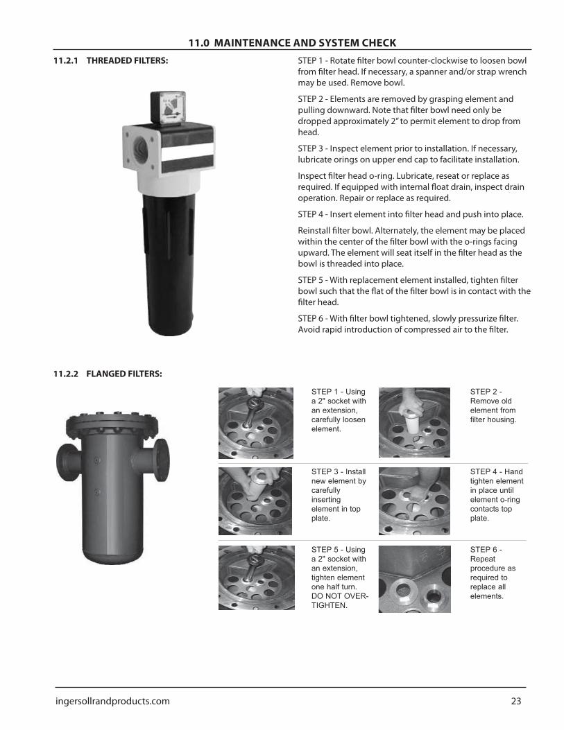
110 MAINTENANCE AND SYSTEM CHECK1121 THREADED FILTERS STEP 1 - Rotate filter bowl counter-clockwise to loosen bowl
from filter head If necessary a spanner andor strap wrench may be used Remove bowl
STEP 2 - Elements are removed by grasping element and pulling downward Note that filter bowl need only be dropped approximately 2rdquo to permit element to drop from head
STEP 3 - Inspect element prior to installation If necessary lubricate orings on upper end cap to facilitate installation
Inspect filter head o-ring Lubricate reseat or replace as required If equipped with internal float drain inspect drain operation Repair or replace as required
STEP 4 - Insert element into filter head and push into place
Reinstall filter bowl Alternately the element may be placed within the center of the filter bowl with the o-rings facing upward The element will seat itself in the filter head as the bowl is threaded into place
STEP 5 - With replacement element installed tighten filter bowl such that the flat of the filter bowl is in contact with the filter head
STEP 6 - With filter bowl tightened slowly pressurize filter Avoid rapid introduction of compressed air to the filter
Turn control power off per shutdown procedures described in Section 97
WARNING
To avoid injury depressurize dryer before performing any service
Once the dryer has been depressurized replace the muffler
Follow normal start-up procedures as described in Section 9
114 NO-LOSS DRAIN VALVES
Periodically clean all no-loss drain valves Cleaning can be accomplished by removing the no-loss drain removing the mufflers and removing the valve bodies from the manifold Check and replace o-rings as necessary If the no-loss drain valves fail to operate check the following
Control Circuit - Verify that the no-loss drain is receiving electric current
Burned out no-loss drain coil
Highlow voltage - Voltage should be +- 10 of nameplate readings
No-loss drain valve leaking - Disassemble clean and repack or replace
115 PILOT OPERATED ACTUATOR
Should the actuator fail to rotate disconnect the pilot lines to check if the actuator is receiving pilot pressure
If the actuator is receiving pressure
Verify that control pressure is 75 psig min
Ensure the inlet valve is not pluggedbull Normally Closed (NC) Valves For NC purge valves the top port is plugged Control air is supplied to the back port If air vents out of the back port continuously when the solenoid is de-energized it will exhaust through the top of the solenoid If this condition is observed the internal seals are leaking and must be replaced
116 DESICCANT CHANGEOUT PROCEDURE
WARNING
To avoid injury depressurize dryer before performing any service
bull
bull
bull
bull
bullbull
bull
bullbull
CAUTIONBe sure to wear respiratory protection during the draining and filling process to minimize inhalation of desiccant as desiccant will produce dust during this procedure
NOTICEEach dryer is shipped with a desiccant sample kit to allow the desiccant to be sent for analysis This kit can be used to have the condition of the desiccant verified by laboratory analysis Please follow the instructions found in the kit
Desiccant dryers are furnished with fill and drain ports on each desiccant tower Remove the caps on both ports
To assist in getting the desiccant to flow from the tower insert a small rod in to the drain port as necessary This may be required as the desiccant is packed into the towers which may interfere with the desiccant flow from the towers
Retainer screens located at the inlet and outlet piping connections of the tower are removable on all models It is suggested that these screens be removed and cleaned at the time of desiccant changeout These screens can be accessed by disconnecting the upper and lower manifolds from the dryer towers
After cleaning the retainer screens replace screens and reattach the outlet port plug
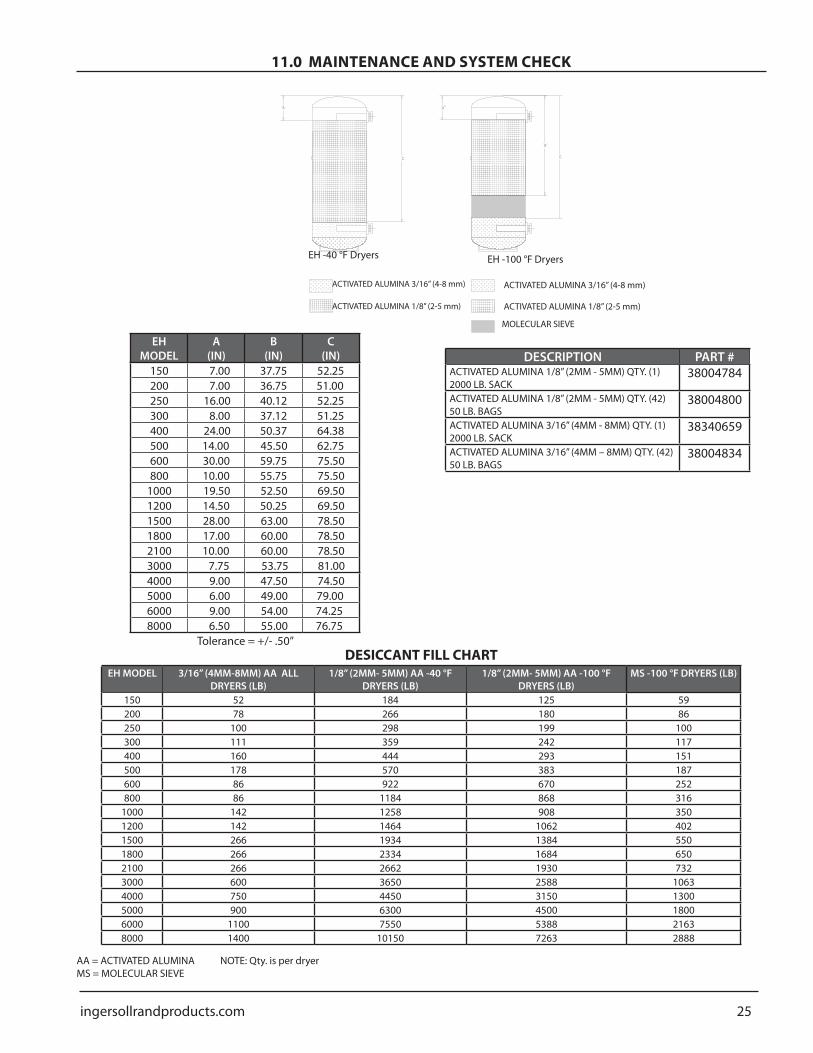
With the fill port plug removed fill the dryer tower with the appropriate grade and size desiccant The level and grade of the desiccant should be consistent with the Desiccant Fill Chart
CAUTIONDesiccant quantity positioning and grades must match the corresponding values in the Desiccant Fill Chart Failure to do so may result in poor dryer performance
Once the towers have been filled replace the fill port plug on each tower
Any connections disturbed in the desiccant changeout process should be leak tested prior to re-commissioning the dryer
AA = ACTIVATED ALUMINA NOTE Qty is per dryerMS = MOLECULAR SIEVE
26 ingersollrandproductscom
120 TROUBLESHOOTING
Refer to maintenance descriptions in Section 11as required for trouble shooting procedures
PROBLEM PROBABLE CAUSE CORRECTIVE ACTIONElevated dew point Insufficient purge rate Check purge flow settings
Check purge piping for obstruction Clean purge piping and muffler
Inlet air pressure below design condition Check pressure source
Flow rate higher than design condition Check flow rate and cause for increased demandInlet temperature above design condition Check aftercooler clean and service as necessary
Entrained water entering desiccant bed Check airmoisture separator and pre-filter Replace dryer desiccant if necessary
Desiccant contaminated by oil Install suitable pre-filter Replace dryer desiccantExcessive pressure drop in dryer
Excessive flow rate Check flow rate and cause for increased air demand
Excessive back pressure in regenerating tower (Above 5 PSIG)
Air is leaking across valve Check inlet valve Verify inlet valve is closed to purging tower (0 PSIG tower)
Excessively high pressure at the purge gage (Blower and Heatless Modes)
Improper calibration Check gauge against tower gauges when in switching sequence Replace gauge as required
Failure to Shift (Switching Failure)
No input power Check power inputDefective solenoid valve Check no-loss drain valveNo pilot air Low pilot air pressure Check pilot air line Check that control air line filter is clean Check
regulator setpointDefective pressure switch Check switch Open pressure gt 65 psig close pressure lt 40 psig
Failure to Shift (Dryer fails to pressurize)
Faulty purge valve Check purge valve and its no-loss drain valve Check that repressurization circuit is sending control signal
Failure to Shift (Dryer fails to depressurize)
Purge valve does not open Purge valve stuck in closed position
Check no-loss drain valve Repair and replace if necessary
Heater High Temp Alarm (Heater runs continuously)
Contactor stuck closed Replace contactorDefective thermocouple Replace thermocoupleDefective temperature control Replace temperature control
SWITCH LOW PRESSURE FAIL TO SHIFT 600924 600924 600924 600924 600924 2THERMOSTAT HEATER HITEMP SFTY 633601 633601 633601 633601 633601 1TRANSFORMER CONTROL 015KVA 600191 600191 600191 600191 600191 1TRANSMITTER DEWPOINT (EMS OPTION) 633856 633856 633856 633856 633856 1 1 1 1VALVE PURGE ADJUSTMENT HAND OP 680029 680429 680429 680429 680430 1VALVE INLET AIR OP 632199 632200 632200 632200 632201 2VALVE PURGE AIR OP 632199 632199 632199 632199 632200 2VALVE BALL CONTROL AIR 14rdquo 681621 681621 681621 681621 681621 1VALVE PURGE CHECK 633714 633731 633731 633731 633714 2VALVE OUTLET FLOW CHECK 632790 632791 632791 632791 632792 2VALVE SAFETYRELIEF 630730 630730 630730 630730 630730 2VALVE CONTROL AIR SOLENOID 4 WAY 633604 633604 633604 633604 633604 4
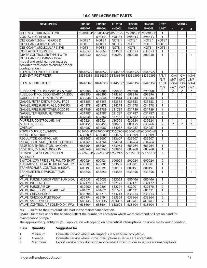
NOTE 1 Refer to the Desiccant Fill Chart in the Maintenance section
Spare Quantities under this heading reflect the number of each item which we recommend be kept on hand for maintenance or repair
The appropriate quantity for your application will depend on how critical interruptions in service are to your operation
Class Quantity Suggested for
1 Minimum Domestic service where interruptions in service are acceptable 2 Average Domestic service where some interruptions in service are acceptable 3 Maximum Export service or for domestic service where interruptions in service are unacceptable
48 ingersollrandproductscom
160 REPLACEMENT PARTS
DESCRIPTION EH5004H000A
EH6004H000A
EH8004H000A
EH10004H000A
EH12004H000A
QTYUNIT
SPARES
1 2 3
BLUE MOISTURE INDICATOR 705001-SP 705001-SP 705001-SP 705001-SP 705001-SP 1DESICCANT 2-5mm GRADE D NOTE 1 NOTE 1 NOTE 1 NOTE 1 NOTE 1 NOTE 1DESICCANT 4-8mm GRADE D NOTE 1 NOTE 1 NOTE 1 NOTE 1 NOTE 1 NOTE 1DESICCANT MOLECULAR SIEVE NOTE 1 NOTE 1 NOTE 1 NOTE 1 NOTE 1 NOTE 1DISPLAY BOARD PANEL 633653 633653 633653 633653 633653 1 1 1 1DRYER CONTROLLER TYPE 4 WITH DESICCANT PROGRAM ( Dryer model and serial number must be provided with order to ensure proper configuration )
SWITCH LOW PRESSURE FAIL TO SHIFT 600924 600924 600924 600924 600924 2THERMOSTAT HEATER HITEMP SFTY 633601 633601 633601 633601 633601 1TRANSFORMER CONTROL 015KVA 600191 600191 600191 600191 600191 1TRANSMITTER DEWPOINT (EMS OPTION) 633856 633856 633856 633856 633856 1 1 1 1VALVE PURGE ADJUSTMENT HAND OP 680430 680712 680712 632053 632053 1VALVE INLET AIR OP 632170 632170 632170 632170 632170 2VALVE PURGE AIR OP 632200 632200 632200 632200 632200 2VALVE BALL CONTROL AIR 14rdquo 681621 681621 681621 681621 681621 1VALVE CHECK PURGE 633714 633708 633708 633708 633708 2VALVE CHECK OUTLET FLOW 632792 632792 632794 632794 632794 2VALVE SAFETYRELIEF 630730 680896 680896 680896 680896 2VALVE CONTROL AIR SOLENOID 4 WAY 633604 633604 633604 633604 633604 4
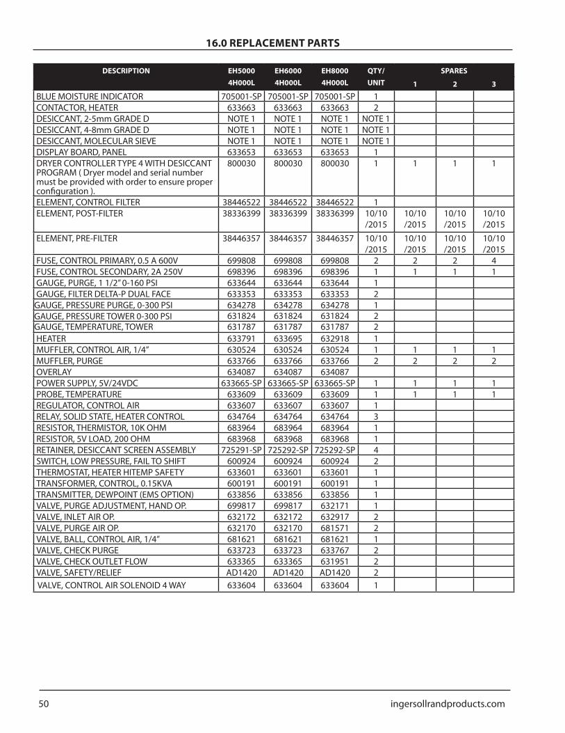
NOTE 1 Refer to the Desiccant Fill Chart in the Maintenance section
Spare Quantities under this heading reflect the number of each item which we recommend be kept on hand for maintenance or repair
The appropriate quantity for your application will depend on how critical interruptions in service are to your operation
Class Quantity Suggested for
1 Minimum Domestic service where interruptions in service are acceptable 2 Average Domestic service where some interruptions in service are acceptable 3 Maximum Export service or for domestic service where interruptions in service are unacceptable
ingersollrandproductscom 49
160 REPLACEMENT PARTS
DESCRIPTION EH15004H000A
EH18004H000L
EH21004H000L
EH30004H000L
EH40004H000L
QTYUNIT
SPARES
1 2 3BLUE MOISTURE INDICATOR 705001-SP 705001-SP 705001-SP 705001-SP 705001-SP 1CONTACTOR HEATER - 698343 698343 698343 698343 1DESICCANT 2-5mm GRADE D NOTE 1 NOTE 1 NOTE 1 NOTE 1 NOTE 1 NOTE 1DESICCANT 4-8mm GRADE D NOTE 1 NOTE 1 NOTE 1 NOTE 1 NOTE 1 NOTE 1DESICCANT MOLECULAR SIEVE NOTE 1 NOTE 1 NOTE 1 NOTE 1 NOTE 1 NOTE 1DISPLAY BOARD PANEL 633653 633653 633653 633653 633653 1DRYER CONTROLLER TYPE 4 WITH DESICCANT PROGRAM ( Dryer model and serial number must be provided with order to ensure proper configuration )
800030 800030 800030 800030 800030 1 1 1 1
ELEMENT CONTROL FILTER 38446522 38446522 38446522 38446522 38446522 1 1 1 1ELEMENT POST-FILTER 38336381 38336399 38336399 38336399 38336399 134
57134 57
134 57
134 57
ELEMENT PRE-FILTER 38446340 38446357 38446357 38446357 38446357 134 57
VALVE PURGE ADJUSTMENT HAND OP 632053 632053 632053 680466 680466 1VALVE INLET AIR OP 632170 632171 632171 632171 632172 2VALVE PURGE AIR OP 632200 632201 632201 632201 632170 2VALVE BALL CONTROL AIR 14rdquo 681621 681621 681621 681621 681621 1VALVE CHECK PURGE 633708 633713 633713 633713 633713 2VALVE CHECK OUTLET FLOW 632794 632794 633364 633364 633364 2VALVE SAFETYRELIEF AD1415 AD1415 AD1415 AD1415 AD1415 2VALVE CONTROL AIR SOLENOID 4 WAY 633604 633604 633604 633604 633604 4
NOTE 1 Refer to the Desiccant Fill Chart in the Maintenance section Spare Quantities under this heading reflect the number of each item which we recommend be kept on hand for maintenance or repair The appropriate quantity for your application will depend on how critical interruptions in service are to your operation
Class Quantity Suggested for
1 Minimum Domestic service where interruptions in service are acceptable 2 Average Domestic service where some interruptions in service are acceptable 3 Maximum Export service or for domestic service where interruptions in service are unacceptable
50 ingersollrandproductscom
160 REPLACEMENT PARTS
DESCRIPTION EH50004H000L
EH60004H000L
EH80004H000L
QTYUNIT
SPARES
1 2 3
BLUE MOISTURE INDICATOR 705001-SP 705001-SP 705001-SP 1CONTACTOR HEATER 633663 633663 633663 2DESICCANT 2-5mm GRADE D NOTE 1 NOTE 1 NOTE 1 NOTE 1DESICCANT 4-8mm GRADE D NOTE 1 NOTE 1 NOTE 1 NOTE 1DESICCANT MOLECULAR SIEVE NOTE 1 NOTE 1 NOTE 1 NOTE 1DISPLAY BOARD PANEL 633653 633653 633653 1DRYER CONTROLLER TYPE 4 WITH DESICCANT PROGRAM ( Dryer model and serial number must be provided with order to ensure proper configuration )
800030 800030 800030 1 1 1 1
ELEMENT CONTROL FILTER 38446522 38446522 38446522 1ELEMENT POST-FILTER 38336399 38336399 38336399 1010
20151010 2015
1010 2015
1010 2015
ELEMENT PRE-FILTER 38446357 38446357 38446357 1010 2015
120 TROUBLESHOOTING 26130 GENERAL ARRANGEMENT 27140 WIRING DIAGRAM 41150 FLOW DIAGRAM 44160 REPLACEMENT PARTS 47170 ENGINEERING SPECIFICATIONS 51
ingersollrandproductscom 3
20 INTRODUCTION
The Company warrants that the equipment manufactured by it and delivered hereunder will be free of defects in material and workmanship for a period of twelve months from the date of placing the Equipment in operation or eighteen months from the date of shipment from the factory whichever shall first occur The Purchaser shall be obligated to promptly report any failure to conform to this warranty in writing to the Company in said period whereupon the Company shall at its option correct such nonconformity by suitable repair to such equipment or furnish a replacement part FOB point of shipment provided the Purchaser has stored installed maintained and operated such Equipment in accordance with good industry practices and has complied with specific recommendations of the Company Accessories or equipment furnished by the Company but manufactured by others shall carry whatever warranty the manufacturers have conveyed to the Company and which can be passed on to the Purchaser The Company shall not be liable for any repairs replacements or adjustments to the Equipment or any costs of labour performed by the Purchaser or others without Companyrsquos prior written approval
The effects of corrosion erosion and normal wear and tear are specifically excluded Performance warranties are limited to those specifically stated within the Companyrsquos proposal Unless responsibility for meeting such performance
warranties are limited to specified tests the Companyrsquos obligation shall be to correct in the manner and for the period of time provided above
THE COMPANY MAKES NO OTHER WARRANTY OR REPRESENTATION OF ANY KIND WHATSOEVER EXPRESSED OR IMPLIED EXCEPT THAT OF TITLE AND ALL IMPLIED WARRANTIES OF MERCHANT ABILITY AND FITNESS FOR A PARTICULAR PURPOSE ARE HERBY DISCLAIMED
Correction by the Company of non conformities whether patent or latent in the manner and for the period of time provided above shall constitute fulfilment of all liabilities of the Company for such non conformities whether based on contract warranty negligence indemnity strict liability or otherwise with respect to or arising out of such Equipment
The Purchaser shall not operate Equipment which is considered to be defective without first notifying the Company in writing of its intention to do so Any such use of Equipment will be at Purchaserrsquos sole risk and liabilityNote that this is Ingersoll Rand standard warranty Any warranty in force at the time of purchase of the equipment or negotiated as part of the purchase order may take prec-edence over this warranty
0 = Standard 0 = Standard A = Filters AttachedL = Filters Loose
Nominal Flows indicated are for 100degF inlet temperature 100degF ambient temperature and 100 psig compressed air pressure
The Ingersoll Rand Heatless Desiccant Dryers are designed to adsorb moisture from compressed air The dryers are constructed with two towers each containing desiccant beads that alternate between online (drying) and offline (regenerating) modes yielding a continuous stream of dry air at the dryerrsquos outlet
During normal operation wet air passes through the on line tower and water vapor from the air is adsorbed (collected) on the desiccant beads While air is being adsorbed in the online tower the moisture on the desiccant in the offline tower is removed by a process called desorption (regeneration) In standard heat reactivated operation after
an initial rapid depressurization a portion of dried air from the on-line tower passes through a heater and over the desiccant bed and carries the moisture off the bed and out the dryerrsquos exhaust With the dryerrsquos Bi- Mode feature the dryers may also be operated in a Heatless mode which uses more purge air but does not require use of the heater
The continuous alternating process of adsorption and desorption is controlled using a timer that switches the towers in a specific timed sequence Very dry compressed air dew points are achieved through the continuous switching and operation of this dryer Ingersoll Rand offers dryers to provide either -40degF or -100degF pressure dew point outlet air
30 WARRANTY
4 ingersollrandproductscom
Because an air dryer is pressurized and contains rotating parts the same precautions should be observed as with any piece of machinery of this type where carelessness in operation or maintenance could be hazardous to personnel In addition to obvious safety rules that should be followed with this type of machinery safety precautions as listed below must be observed
Only qualified personnel shall be permitted to adjust perform maintenance or repair this air dryer
Read all instructions completely before operating unit
Pull main electrical disconnect switch and disconnect any separate control lines if used before attempting to work or perform maintenance on the unit
Do not attempt to service any part while machine is in an operational mode
Do not attempt to remove any parts without first relieving the entire air system of pressure
Do not operate the dryer at pressures in excess of its rating
Do not operate the dryer without guards shields and screen in place
Inspect unit daily to observe and correct any unsafe operating conditions
1
2
3
4
5
6
7
8
OSHAHeading Descriptions
WARNINGldquoWarningrdquo is used to indicate a hazardous situation which has some probability of death or severe injury Warning should not be considered for property damage accidents unless personal injury risk is present
ATTENTIONldquoCautionrdquo is used to indicate a hazardous situation which may result in minor or moderate injury
NOTICEldquoNoticerdquo is used to indicate a statement of company policy as the message relates directly or indirectly to the safety of personnel or protection of property Notice should not be associated directly with a hazard or hazardous situation and must not be used in place of ldquoDangerrdquo ldquoWarningrdquo or ldquoCaution
NOTICEThe user of any air dryer manufactured by Ingersoll Rand is hereby warned that failure to follow the above Safety and Operation Precautions may result in personal injury or equipment damage However Ingersoll Rand does not state as fact nor does it mean to imply that the preceding list of Safety and Operating Precautions is all inclusive and further that the observance of this list will prevent all personal injury or equipment damage
60 SAFETY AND OPERATION PRECAUTIONS
50 RECEIVING AND INSPECTION51 INSPECTION
Upon receiving your Ingersoll Rand air dryer please inspect the unit closely Visually check the dryer to make certain that all air lines and electrical connections are securely fastened and were not damaged in transit If rough handling has been detected please note it on your delivery receipt especially if the dryer will not be immediately uncrated Obtaining the delivery personrsquos signed agreement to any noted damage will facilitate any insurance claim
52 UNPACKING AND HANDLING
Refer to labels on the dryer for the appropriate means for lifting or moving the dryer When lifting the dryer ensure that no stress is applied to the piping or valving Refer to Section 102 for locating and mounting of dryer
WARNINGUnder no circumstances should any person attempt to lift heavy objects without proper lifting equipment (ie crane hoist slings or fork truck) Lifting any unit without proper lifting equipment can cause serious injury
ingersollrandproductscom 5
70 PRINCIPLES OF OPERATION
71 INTRODUCTION
As described in Section 1 water vapor is removed from compressed air by diverting air flow alternately between two towers filled with activated alumina desiccant While one tower processes the compressed air stream adsorbing water vapor the opposite tower regenerates by desorbing the water vapor and venting it to atmosphere
The Microprocessor Controller provides the ability to select between heated or heatless regeneration Both heated and heatless regeneration methods are described in the following sections
NOTICEThe Microprocessor Controller must be in the OFF position prior to changing the mode (heated purge heatless) of the dryer After the change is made and the Microprocessor Control is subsequently turned ON the dryer will be in the new mode of operation
72 DRYING CYCLE
Saturated compressed air enters the dryer and is diverted to the appropriate tower by the Inlet Flow Valves (Refer to the Process and Instrumentation Diagram) The Right Tower Flow Valve is actuated to a closed position to prevent air flow from entering the regenerating tower Simultaneously the Left Tower Flow Valve is actuated to an open position allowing air flow to the drying tower During this time the Left Tower Purge Valve is actuated to a closed position preventing the compressed air from venting to atmosphere As the compressed air flows through the desiccant material in the left tower at pressure removal of water vapor from the air stream begins to occur through adsorption In the adsorption process the desiccant material draws water vapor out of the compressed air and ldquoholdsrdquo it until the left tower drying cycle is complete Compressed air flows out of the tower for delivery to the process use The Outlet Flow Check Valves provide air flow diversion to the outlet air connection of the dryer
73 REGENERATION CYCLE
Previously adsorbed moisture removed from the process stream gets stripped or desorbed from the desiccant material in the regeneration process The first stage of regeneration is tower depressurization After the Inlet Flow Valves are switched to divert air flow away from the regenerating tower the appropriate Purge Valve will be opened and the tower will be depressurized Through rapid depressurization a significant portion of the previously adsorbed water vapor is stripped off of the desiccant material and exhausted to atmosphere
CAUTIONAny time the dryer is switched between two operating modes care must be taken to ensure the purge adjustment valve is adjusted correctly Refer to the specification sheet in this manual for proper gauge setting
731 SETTING THE REGENERATION AIR FLOW
Proper setting of the purge flow is necessary to achieve proper dryer performance in the heatless and externally heated modes Setting the purge flow too high will waste compressed air and if set too low the dryer will not achieve dew point performance The purge adjustment manifold consists of the purge adjustment valve purge pressure gauge and the purge orifice The purge pressure gauge is located between the purge adjustment valve and purge orifice Manually adjust the purge adjustment valve until the reading on purge pressure gauge matches the purge pressure setting listed on the tag attached to the gauge Note that there are two purge gauge values corresponding to each mode of operation
732 HEATED PURGE REGENERATION
In the heat reactivated mode the dryer uses 75 of dry compressed air expanded to atmospheric pressure However after air expansion through the Purge Orifice the purge air is passed through the purge heater This expanded heated purge air is then passed through the regenerating tower and exhausted out to atmosphere After a three minute delay the heating process occurs for 2 hours and 57 minutes During the heating process the electric heater is cycled on and off by Ingersoll Randrsquo temperature controller Solid State relay This advanced controller precisely monitors purge air temperature and adjusts the heater temperature accordingly This results in a regeneration air temperature that remains within 15 degF from the heater setpoint for the entire regeneration cycle eliminating temperature swings associated with contactor-based heating system Upon completion of the three-hour heating period the electric heater turns off The dry regeneration air continues to flow for 57 minutes in order to cool down the desiccant bed
6 ingersollrandproductscom
70 PRINCIPLES OF OPERATION733 HEATLESS PRESSURE SWING REGENERATION
In the heatless mode following depressurization regeneration uses approximately 15 of the dry compressed air expanded to atmospheric pressure to complete the desorption process As shown on the P amp ID the compressed air exits the drying tower and a portion of the air flows through the purge adjustment valve and the Purge Orifice Once the air has passed through the Purge Orifice it expands to atmospheric pressure and continues the regeneration process Desorption occurs as the desiccant releases water vapor into the regeneration air and is exhausted through the Outlet Purge Valves
74 TOWER REPRESSURIZATION
Upon completion of tower regeneration and prior to changing the Inlet Flow Valve position to switch towers the regenerated tower must be repressurized Repressurization is accomplished by closing the appropriate purge valve Closing the Purge Valve allows the regeneration air to pressurize the tower
NOTICEFailure to repressurize prior to tower switchover will result in shocking the desiccant material and cause premature desiccant dusting
741 HEATED PURGE REPRESSURIZATION
Three minutes prior to tower switch-over repressurization is accomplished by closing the appropriate Purge Valve When the Purge Valve closes the regeneration air begins to pressurize the tower If the dryer is supplied with the optional repressurization piping the Repressurization Valve opens allowing some additional air from the outlet of the dryer to assist the purge air and to ensure adequate pressurization During normal tower regeneration the Repressurization Valve is held closed so that the only source of air for regeneration passes through the purge adjustment assembly
742 HEATLESS PRESSURE SWING REPRESSURIZATION
45 seconds prior to tower switch-over repressurization is accomplished by closing the appropriate Purge Valve When the Purge Valve closes the regeneration air begins to pressurize the tower If the dryer is supplied with the optional repressurization piping the Repressurization Valve opens allowing some additional air from the outlet of the dryer to assist the purge air and to ensure adequate pressurization During normal tower regeneration the Repressurization Valve is held closed so that the only source of air for regeneration passes through the purge adjustment assembly
75 VALVES
Flow and Purge Valves are two-way valves that are switched using airoperated double-acting actuators Each valve is actuated by a four-way solenoid valve as shown on the P amp ID
NOTICEActuated valves require 75 psi min pressure for proper operation
The Inlet Flow Valves are connected as normally open valves When the dryer is de-energized the solenoid valves for the Inlet Flow Valves supply control air to the ldquoopenrdquo port on the appropriate valve actuator
Purge Valves are connected as normally closed valves When the dryer is de-energized the solenoid valves for the Purge Valves supply control air to the ldquoclosedrdquo port on the appropriate valve actuator
Outlet Check Valves as well as Purge Check Valves are single-direction check valves that will allow flow in the direction shown on the P amp ID but not allow flow in the opposite direction
76 CONTROLS
761 MICROPROCESSOR CONTROL USER INTERFACE
The Microprocessor Control display provides the user with the operating parameters and their corresponding values When power is supplied to the dryer the Microprocessor Control will illuminate and default to the ldquoStandbyrdquo mode displaying the ldquoPress ONrdquo prompt
The following illustration summarizes the keypad functions
FIGURE 1 - MICROPROCESSOR CONTROLLER
ingersollrandproductscom 7
70 PRINCIPLES OF OPERATION
BUTTONS
ON Initiates PLC program Begins system monitoring and valve switching functions
OFF Stops PLC program Stops valve switching functions Initiates shutdown sequence Opens Inlet Flow Valves Closes Purge Valves
SELECT DISPLAY Allows the user to scroll through the available displays The last display selected will remain displayed as the default display
+ - Allows user to modify set point values Set point values cycle through a fixed range Also allows entering negative numbers in Factory Modes
or ldquoblankrdquo button Allows user to step backwards to the previous level of the menu
bull
bull
bull
bull
bull
RESET Pressing once clears the local alarm indication and de-energizes the remote alarm contact for many alarm conditions Should the alarm condition persist the alarm will return after the alarm inhibit time has expired
SET Permits the adjustment of parameters in FACTORY MODES
ENTER Used to accept changed parameters and set point values
TEST Not used in Desiccant Dryer applications
i Restricted Level access for factory use only
762 STATUS PANEL USER INTERFACE
The status panel provides clear indication of dryer status via bright LED indicators The following illustration summarizes the panelrsquos features
bull
bull
bull
bull
bull
Secadora apagada alarma (rojo)
Regeneracioacuten de la torrederecha (amarillo)
Funcionamiento delcalefactor (verde)
Secado de la torre derecha(amarillo)
Secadora encendida(verde)
Regeneracioacuten de la torreizquierda (amarillo)
Secado de la torreizquierda (amarillo)
Figura 2 - Panel de estadoFIGURE 2 - STATUS PANEL
Dryer ON (Green)
Left Tower Regeneration (Yellow)
Left Tower Drying (Yellow)
Dryer OFF Alarm (Red)
Right Tower Regeneration (Yellow)
Right Tower Drying (Yellow)
Heater Operation (Green)
8 ingersollrandproductscom
NOTE Ingersoll Rand solid state temperature controller modulates the heater repeatedly during the heating cycle Pulsating of the heater LED will occur as a result and should be considered normal dryer operation
763 MICROPROCESSOR CONTROL DISPLAY PARAMETERS
The Microprocessor Controller is capable of displaying a number of system parameters in the default CUSTOMER MODE The following summarizes the parameters that can be accessed by depressing the SELECT DISPLAY button from the Microprocessor Controller (Note that some displays are optional and may not appear on all models)
Tower Status LT DRY RT REGEN or LT REGEN RT DRY Provides visual confirmation of tower drying and regenerating status
Step Timer ie STEP 4 TIME 120 Information screen displaying the current step in the program and the time remaining for the displayed step
Dew Point Temperature (OPTIONAL) - DEW POINT TEMP XX When equipped with the Energy Management System (EMS) feature provides accurate display of dryer outlet pressure dew point
Purge Status (OPTIONAL) - PURGE NO PURGE Indicates whether unit is currently consuming purging air Requires EMS
Heater Status (HEATED PURGE MODE ONLY) - On OFF Indicates that the heater is being given a signal to heat the purge air
Heater Temperature (HEATED PURGE MODE ONLY) - HEATER TEMP XX Indicates the heater temperature set point
Alarms ALARM LIST - PRESS ENTER Depressing ltENTgt at this prompt permits viewing of current alarm status and alarm history which includes the time and date of the alarm occurrence
Operating amp Purge Times - OPERATING TIMES - PRESS ENTER Depressing ltENTgt at this prompt provides access to the operating and purge hours of operation
Operating Mode OPERATING MODE HEATLESS HEATED PURGE EH dryers are capable of operating in Heated Purge and Heatless Pressure Swing modes This display indicates mode of operation for dryer
Once the last screen is displayed depressing the SELECT DISPLAY button will return the display to the top of the list
bull
bull
bull
bull
bull
bull
bull
bull
bull
77 TIMING SEQUENCE
All timing functions are performed by Ingersoll Randrsquo Microprocessor Controller an advanced micro PLC designed exclusively for Ingersoll Rand dryers The Microprocessor Controller is completely programmed at the factory and does not require any further adjustment The standard timing cycle switches the Inlet Flow Valve which alternates the drying tower At the same time as the Inlet Flow Valve opens the appropriate tower Purge Valve opens to begin the purge flow generation Once the purge regeneration flow portion of the dryer cycle is complete tower repressurization begins as previously described
771 HEATED PURGE TIMER CYCLE
In the externally heated operating mode the Microprocessor Control controls an eight-hour cycle The tower switch-over occurs every four hours Ten seconds after switch-over occurs the regenerating tower depressurizes for 50 seconds After depressurization heated regeneration begins and extends for 2 hours and 58 minutes The heating supply is turned off and the purge air flow continues for the next 58 minutes The purge air supply during this time is used to cool down the hot desiccant After the cool down stage a repressurization stage repressurizes the offline tower for 3 minutes
772 HEATLESS PRESSURE SWING TIMER CYCLE
In the heatless operating mode the Microprocessor Control controls a ten-minute cycle The tower switch-over occurs every five minutes Ten seconds after tower switch-over occurs the regenerating tower depressurizes and tower regeneration occurs for four minutes and 15 seconds At that time tower repressurization begins
78 RESTART MODES
The Microprocessor Controller includes a Shutdown Sequence that is activated when the dryer OFF button is depressed This feature positions the valves to their failsafe position and resets the program and is the recommended method of shutting down the dryer When the dryer is subsequently energized the dryer is ready to run at the start of the program Should however power be cut to the dryer before the Shutdown Sequence has been initiated as would be the case from a power failure the dryer can be configured to restart in one of two restart modes Note that when the dryer is shut down using the OFF button the dryer will require user intervention to restart the dryer
70 PRINCIPLES OF OPERATION
ingersollrandproductscom 9
70 PRINCIPLES OF OPERATION
781 MANUAL MODE (ZERO)
Ingersoll Rand dryers are shipped from the factory in the Manual Mode After power is re-supplied to the dryer the user will be presented with the ldquoPRESS ONrdquo display The valve switching and timing operations will only start once the ON button is depressed In this configuration to restart the dryer the user must manually depress the ON button on the Microprocessor Control panel
782 AUTO RESTART MODE (LAST)
In this mode the dryer will re-start automatically once power is applied to the dryer The Microprocessor Control will pick up where it left off in the program once power is applied
79 OPERATING TIMES
In the CUSTOMER MODE the Microprocessor Controller provides access to the operating hours of the dryer The following describe the method to access and review the operating and purge hours for the dryer
Depress the SELECT DISPLAY button until the OPERATING TIMES display appears
Depressing the ENTER button enters the OPERATING TIMES menu
Depressing the SELECT DISPLAY button displays the cumulative operating hours of the dryer
Depressing the SELECT DISPLAY button displays the cumulative hours the dryer has used purge air
Depressing the ENTER button returns the display to the top of the OPERATING TIMES menu
Depressing the 1048789 button returns the controller to theCUSTOMER MODE
10 ingersollrandproductscom
80 ALARMS AND INDICATORS
81 MOISTURE INDICATOR (STANDARD)
The moisture indicator senses a sample of the control air which is taken from the dryer outlet The indicator provides a gross indication of dew point deterioration at the outlet of the dryer Under normal operating conditions the indicator is blue In the event of a dryer malfunction or prolonged dryer shut down it will turn gray in the presence of moisture
82 HEATER HIGH TEMPERATURE ALARM WITH IN-TERLOCK (STANDARD)
The Heater High Temperature Alarm monitors the internal temperature of the heater housing Should a component failure occur or system conditions result in the heater temperature rising above the alarm set point the dryer will alarm During the alarm condition the heater is prevented from operating the Microprocessor Control halts the program at the point where the alarm occurred and displays the condition in the Microprocessor Control LCD display The dryer will be unable to be reset until the temperature of the heater has fallen below the alarm point To reinstate the dryer depress the RESET button on the Microprocessor Controller AND manually reset the Heater High Temperature Safety in the electrical enclosure Note that the alarm condition will return should proper corrective action not be taken
83 HEATER FAILURE ALARM (STANDARD)
This feature produces an alarm should the heater fail to generate heat at the beginning of the heating cycle During the initial ten minutes of the heating cycle the Microprocessor Controller monitors the heater temperature Should the heater temperature fail to rise to 150 degF within the ten minute period the Heater Failure Alarm will be triggered During this alarm condition power to the heater is removed and the program is halted Depressing the RESET button on the Microprocessor Controller will reinstate the program and provided the heater problem has been remedied continue with normal operation
84 FAILURE TO SHIFT ALARM (STANDARD)
Ingersoll Rand Failure To Shift Alarm monitors the dryer sequencing functions to insure proper dryer operation by sensing the pressure in each tower via tower pressure switches Should one of the following conditions occur the Microprocessor Controller will communicate the alarm condition There are several types of switching failure modes that can be detected by the Failure To Shift Alarm feature They are as follows
841 FAILURE TO REPRESSURIZE
At the end of the repressurization stage of the dryer operation both towers should be at line pressure Should the pressure switches indicate that both towers are not at line pressure the Failure to Shift Alarm will activate and the Microprocessor Control will stop the program at itrsquos current position in the program The user must depress the RESET button followed by the ON button at which time the Microprocessor Control will start at the beginning of the program
842 FAILURE TO DEPRESSURIZE
At the end of the depressurization stage of the dryer operation the regenerating tower should be at atmospheric pressure Should the pressure switches indicate that this is not the case the Failure to Shift Alarm will activate and the Microprocessor Control will stop the program at itrsquos current position in the program The user must depress the RESET button followed by the ON button at which time the Microprocessor Control will start at the beginning of the program
85 HIGH DEW POINT ALARM (INCLUDED WITH EMS)
The purpose of the High Dew Point Alarm is to provide the operator an alarm indication should the equipment fail to supply air at its designed pressure dew point The EMS dew point sensor communicates the pressure dew point reading to the Microprocessor Controller Should the pressure dew point rise above the alarm set point the Microprocessor Controller will display the alarm condition on the controller screen
86 ENERGY MANAGEMENT SYSTEM (EMS) (OP-TIONAL)
EMS is an energy savings feature that matches moisture loading and regeneration energy usage Drying equipment is typically operated below full flow rating andor below maximum water loading capacity of the desiccant bed The EMS option includes a dew point transmitter that transmits the outlet pressure dew point to the Microprocessor Controller The Microprocessor Controller displays the outlet pressure dew point in real-time The EMS feature utilizes the data communicated from the dew point sensor and extends the normal timed switching sequence in proportion to the moisture loading on the dryer When the EMS feature is turned off all switching sequences occur as described in Section 73 When the EMS feature is activated the drying sequence is governed by the outlet pressure dew point as
ingersollrandproductscom 11
80 ALARMS AND INDICATORSmeasured by the dew point sensor When the sampled outlet dew point registers below the customer set point (-43degF default for -40degF dryers -102degF on -100degF dryers) an immediate change in dryer operation will not be noticeable The dryer will continue its normal regeneration process through tower re-pressurization Once the tower is re-pressurized both towers will be at line pressure but air will only flow through the tower indicated by the status panel Tower switch over sequence is delayed until the dew point elevates above the EMS set point at which point tower switch over will occur
In addition to monitoring the outlet pressure dew point of the drying tower the EMS feature monitors the temperature of the purge exhaust air on the regenerating tower After a tower switch-over and at the beginning of tower regeneration the purge exhaust temperature will be relatively low (normally 90 to 110degF) The purge exhaust temperature will increase as desiccant regeneration progresses As nearly all of the previously adsorbed moisture is driven off of the desiccant the exhaust temperature will begin to rise The timing for the temperature change will vary depending on moisture loading on the towers When the purge exhaust temperature reaches 195degF which indicates that the desiccant heating is complete the Microprocessor Controller will remove power to the heater Once the heater is turned off the tower cool down process begins and continues for 57 minutes Purge air will continue to exhaust and the exhaust air temperature will continue to rise (250degF is not uncommon) as it removes the heat from the regenerated desiccant material As the cool down progresses the exhaust temperature will begin to decrease After cooling the Purge Valves close and the optional Repressurization Valve (if equipped) opens The off-line tower remains pressurized until the tower switchover sequence is initiated
87 HIGH OUTLET TEMPERATURE (OPTIONAL)
This option provides continuous monitoring of the the dryer discharge air temperature via a thermostat that senses the outlet air temperature during dryer operation Should a high outlet temperature condition exist the alarm is displayed on the Microprocessor Controller to alert maintenance personnel of a malfunction This alarm does not interrupt the dryer program Depressing the RESET button will clear the alarm provided the alarm condition as been addressed Note that the alarm will clear automatically once the high temperature condition is corrected
88 ALARM LIST
The Microprocessor Controller stores the 20 most recent alarm conditions These alarms are stored with the type of alarm as well as the date and time the alarm occurred This list can greatly facilitate troubleshooting the dryer and provide an indication of dryer operation during unattended service The following describe the method to access and review the alarms stored in the Microprocessor Controller
Depress the SELECT DISPLAY button until the ALARM LIST display appears
Depressing the ENTER button enters the ALARM LIST menu
Depressing the SELECT DISPLAY button advances the menu to the current alarm status
12 ingersollrandproductscom
80 ALARMS AND INDICATORS
Depressing the SELECT DISPLAY list displays the most recent of the alarms stored by the Microprocessor Control Refer to the diagram at the end of this section for an explanation of the ALARM LIST Display
Depressing the SELECT DISPLAY button will reveal the previous alarm condition(s) as well as the remaining available alarm placeholders for alarms To EXIT the ALARM LIST perform the following
Depressing the button returns the controller to the top of the ALARM LIST
Depressing the button again returns the controller to the CUSTOMER MODE
Alarm Condition
Time of Alarm (Military Time)
Date of Alarm (Date-Month) Example shows April 11
ingersollrandproductscom 13
90 TECHNICIAN MODEThe Microprocessor Control provides a protected TECHNICIAN MODE to manipulate several parameters not accessible by the casual operator Below is a list of parameters that can be accessed and manipulated by the technician in the TECHNICIAN MODE
Parameter Display Set PointOPERATION MODE OPERATION
MODEHTLS HEATED
ENERGY MANAGEMENTSYSTEM (OPTIONAL)
EMS OFF ON
ENERGY MANAGEMENT SYSTEMSETPOINT (OPTIONAL)
EMS SET POINT -76 - +68
PURGE TEMPERATURE PURGE TEMP OFF ON
RESTART MODE RESTART LAST ZERO
EXTENDED HEATING EXTENDED HTG OFF ON
HIGH DEW POINT ALARMACTIVATION (OPTIONAL)
HIGH DEWPOINT
OFF ON
NOTE Setpoints indicated are adjustable ONLY when dryer is equipped with the Energy Management System option Setpoints are non-adjustable on dryers
91 ENTERING TECHNICIAN MODE
WARNINGTECHNICIAN MODE should only be entered by qualified service personnel Altering the set points in TECHNICIAN MODE will have a significant effect on the operation of the dryer Incorrect set points may damage dryer and cause potential serious injury
To enter the TECHNICIAN MODE perform the following keystrokes
Pressing the ldquo2rdquo and ldquo3rdquo buttons simultaneously enters the TECHNICIAN MODE
Depressing SELECT DISPLAY scrolls through the available parameters
92 OPERATING MODE (BI-MODE)
As described in Section 7 Heat Reactivated Dryers can operate in a heated purge mode as well as a heatless pressure swing mode To change the operation mode of the dryer perform the following keystrokes
Depress the SELECT DISPLAY button until the SET OPERATION MODE screen is displayed
Depress the +- button until the desired dew point is displayed Pressing SELECT DISPLAY saves the current selection
NOTICEThe Microprocessor Controller must be in the OFF position prior to changing the mode (heated purge heatless) of the dryer After the change is made and the Microprocessor Control is subsequently turned ON the dryer will be in the new mode of operation
CAUTIONAny time the dryer is switched between two operating modes care must be taken to ensure the purge adjustment valve is adjusted correctly Refer to the specification sheet in this manual for proper gauge setting
93 HEATER TEMPERATURE SETPOINT (HEATED PURGE MODE ONLY)
The Microprocessor Controller permits the user to adjust the temperature of the heater thereby altering the regeneration temperature in the heated purge mode
WARNINGThe user is advised to only alter the regeneration temperature after being instructed to do so by Ingersoll Rand factory personnel Improper or inappropriate manipulation of the heater temperature can result in degraded dryer performance equipment damage and serious injury Notify Ingersoll Rand Compressed Air Solutions prior to altering the heater temperature
14 ingersollrandproductscom
90 TECHNICIAN MODE
Depress the SELECT DISPLAY button until the HEATER TEMPERATURE SET POINT screen is displayed
Pressing the SET button permits the value of the HEATER TEMPERATURE SETPOINT to be changed
t
Use the numbers on the keypad to enter the desired value for the HEATER TEMPERATURE setpoint
Use the numbers on the keypad to enter the desired value for the HEATER TEMPERATURE setpoint
Use the numbers on the keypad to enter the desired value for the HEATER TEMPERATURE setpoint
Depressing ENTER saves the selected set point
94 ENERGY MANAGEMENT SYSTEM (OPTIONAL)
The Energy Management System option includes a dew point sensor that transmits the outlet pressure dew point to the Microprocessor Controller The Microprocessor Controller displays the outlet pressure dew point in real-time This option package also includes Energy Management System an energy savings feature that matches moisture loading and regeneration energy usage Drying equipment is typically operated below full flow rating andor below maximum water loading capacity of the desiccant bed The Energy Management System feature utilizes the data communicated from the dew point sensor and extends the normal timed switching sequence in proportion to the
moisture loading on the dryer
When the Energy Management System feature is turned off all switching sequences occur as described in Section 73 When the Energy Management System feature is activated the drying sequence is governed by the outlet pressure dew point as measured by the dew point sensor When the sampled outlet dew point registers below the customer set point (-43degF default for -40degF dryers -102degF on -100degF dryers) an immediate change in dryer operation will not be noticeable The dryer will continue its normal regeneration process through tower re-pressurization Once the tower is re-pressurized both towers will be at line pressure but air will only flow through the tower indicated by the status panel Tower switch over sequence is delayed until the dew point elevates above the Energy Management System setpoint at which point tower switch over will occur
NOTICEThe Microprocessor Controller must be in the OFF position prior to changing the mode (heated purge heatless) of the dryer After the change is made and the Microprocessor Control is subsequently turned ON the dryer will be in the new mode of operation
941 ENABLING DISABLING ENERGY MANAGEMENT SYSTEM
The following illustrates the method of accessing and adjusting the Energy Management System feature
Depress the SELECT DISPLAY button until the ENERGY MANAGEMENT SYSTEM screen is displayed
Depress the +- button until the desired set point is displayed Pressing SELECT DISPLAY saves the current selection
ingersollrandproductscom 15
90 TECHNICIAN MODE
942 SETPOINT ADJUSTMENTOn dryers equipped with the optional Energy Management System the setpoint can be adjusted to match the dryers operation to the desired pressure dew point
The following illustrates the method of adjusting the setpoint for the Energy Management System feature
Depress the SELECT DISPLAY button until the EMS SET POINT screen is displayed
Pressing the SET button permits the value of the EMS SETPOINT to be changed
To enter a negative number depress the +- button Otherwise proceed to the next step
Use the numbers on the keypad to enter the desired pressure dew point temperature for the EMS setpoint
Use the numbers on the keypad to enter the desired pressure dew point temperature for the EMS setpoint
Depressing ENTER saves the selected set point
95 PURGE TEMPERATURE (OPTIONAL HEATED PURGE MODE)
On dryers equipped with EMS the temperature of the purge exhaust is monitored and displayed on the Microprocessor Controller After a tower switch-over and at the beginning of tower regeneration the purge exhaust temperature will be relatively low (normally 90 to 110degF) The purge exhaust temperature will increase as desiccant regeneration progresses As nearly all of the previously adsorbed moisture is driven off of the desiccant the exhaust temperature will begin to rise The timing for the temperature change will vary depending on moisture loading on the towers When the purge exhaust temperature reaches 195degF which indicates that the desiccant heating is complete the Microprocessor Controller will remove power to the heater Once the heater is turned off the tower cool down process begins and continues for 57 minutes Purge air will continue to exhaust and the exhaust air temperature will continue to rise (250degF is not uncommon) as it removes the heat from the regenerated desiccant material As the cool down progresses the exhaust temperature will begin to decrease After cooling the Purge Valves close and the optional Repressurization Valve (if equipped) opens The off-line tower remains pressurized until the tower switchover sequence is initiated Activation of the Purge Temperature feature is via the Microprocessor Controller
The following illustrates the method of accessing and activating the Purge Temperature feature
Depress the SELECT DISPLAY button until the PURGE TEMP screen is displayed
Depress the +- button until the desired set point is displayed Pressing SELECT DISPLAY saves the current selection
96 RESTART MODE
Ingersoll Rand dryers can be configured to restart in one of two operating modes As described in Section 78 the dryer may be configured for Manual operation (factory default) or Auto Restart which permits the dryer to operate automatically once power is re-applied to the dryer after a power failure The following illustrates the method of accessing and adjusting the different start modes for the dryer
16 ingersollrandproductscom
90 TECHNICIAN MODE
Depress the SELECT DISPLAY button until the START MODE screen is displayed
To change the start mode from its current selection to the alternate setting depress the +- button until the desired set point is displayed Pressing SELECT DISPLAY saves the current selection
NOTICEThe restart modes will only affect restarting should power be unexpectedly removed from the dryer After proper shut down the dryer will require the user to depress the ON button to initiate the operation of the dryer program
97 EXTENDED HEATING (OPTIONAL)
On dryers equipped with the Energy Management System option the dryer may be operated in an extended heating mode In this mode the heating cycle is extended while the Energy Management System function prolongs the drying cycle This feature is particularly useful when operating the dryer with new desiccant As described earlier in this manual new desiccant has the ability to adsorb more moisture than the dryer can desorb in a fixed regeneration cycle With the Extended Heating operation the Energy Management System feature can be used immediately without the need to age the desiccant To enable the Extended Heating mode perform the following keystrokes
Depress the SELECT DISPLAY button until the EXTENDED HEATING screen is displayed
Depress the +- button until the desired set point is displayed Pressing SELECT DISPLAY saves the current selection
98 HIGH DEW POINT ALARM (OPTIONAL)
981 DESCRIPTION AND ACTIVATION
When the dryer is equipped with the optional Energy Management System feature the dew point sensor transmits the dew point to the Microprocessor Control Should the outlet pressure dew point exceed the customer specified set point High Dew Point Alarm will activate
The following illustrates the method of activating the High Dew Point Alarm feature
Depress the SELECT DISPLAY button until the HIGH DEW POINT screen is displayed
Depress the +- button until the desired set point is displayed Pressing SELECT DISPLAY saves the current selection
982 SETPOINT ADJUSTMENT
On dryers equipped with the optional Energy Management System the High Dew Point Alarm setpoint can be adjusted as follows Factory settings on -40degF dryers is -28degF
The following illustrates the method of adjusting the setpoint for the High Dew Point Alarm feature
Depress the SELECT DISPLAY button until the HIGH DEW POINT SET POINT screen is displayed
Pressing the SET button permits the value of the HIGH DEW POINT ALARM SETPOINT to be changed
To enter a negative number depress the +- button Otherwise proceed to the next step
ingersollrandproductscom 17
90 TECHNICIAN MODE
Use the numbers on the keypad to enter the desired pressure dew point temperature for the EMS setpoint
Use the numbers on the keypad to enter the desired pressure dew point temperature for the HIGH DEW POINT ALARM setpoint
Depressing ENTER saves the selected set point
NOTICEThe High Dew Point Alarm set point should not be greater than the Energy Management System set point Failure to do so will result in an alarm indication Ingersoll Rand recommends setting the High Dew Point Alarm at least 10degF wetter than the Energy Management System setpoints
99 PROGRAM JOG
All heated purge dryers come equipped with a Program Jog feature that is accessible via the Microprocessor Controller This feature allows the dryer cycle to be accelerated for troubleshooting and routine inspection purposes By accessing the Program Jog routine in the Microprocessor Control the customer can advance the program to the next program step Note that the program advance feature will not advance through all steps of the program
WARNINGWhen the Program Jog is initiated in the middle of the heating cycle advancing the program without allowing normal tower cool down will result in an outlet air temperature that may exceed 300degF As such proper precautions must be taken to protect downstream equipment from high temperature exposure
NOTICEDuring the Program Jog routine the display may show intermediate steps in the program that are not active in the current program set up This should be considered normal operation
The Microprocessor Controller will only permit the jog function during specific stages of the program Should the program be at a stage where the program can not advance the following will be displayed
Depress the SELECT DISPLAY button until the JOG MODE display appears The WAIT prompt will appear should the program not be able to advance at this stage
Should the program be at a stage whereby the Microprocessor Control permits the jog feature the following will be displayed
Depress the SELECT DISPLAY button until the JOG MODE display appears The PRESS ENTER prompt will appear along with the current step and remaining time should the program be able to advance at this stage
Depressing the ENTER button advances the program to the next step The display will indicate the next step has been initiated
NOTICEThe Program Jog advances steps 6 8 20 amp 22 which are the longest program steps The balance of the steps are not advanced in Program Jog Mode
NOTICETo exit the TECHNICIAN MODE press the ldquo+ -rdquo key to the initial ldquoSET OPMODErdquo screen and depress the button to return to the CUSTOMER MODE
910 SHUTDOWN SEQUENCE
When the OFF button is pressed SHUTDOWN SEQUENCE will be displayed for 30 seconds During this time the offline tower will represurrize Both main flow valves will open and purged air will cool the heater element
18 ingersollrandproductscom
100 INSTALLATION AND INITIAL START-UP
101 EQUIPMENT APPLICATION GUIDELINES
Ingersoll Rand Regenerative air dryers are shipped complete with desiccant up to and including model EH2100 On larger units the desiccant is packaged separately for ease in handling Refer to Section 96 for desiccant fill procedures
To achieve the best dryer performance carefully check that the design and installation requirements outlined below are satisfied
Ingersoll Rand dryers are available with an operating range from 75 - 150 PSIG Air available for your usage will vary with operating pressure The maximum design pressure of the standard Desiccant Dryers is 150 PSIG For units that require higher operating pressures consult your Ingersoll Rand representative
Dryers are sized according to flow and pressure drop not pipe size The difference between the inlet and the outlet flow is the amount of purge air required This air is exhausted to atmosphere and is not available for use downstream Make certain air supply to dryer meets air demand plus purge air requirements
NOTICEThe standard dryer is not rated for any gas other than air
NOTICEIngersoll Rand recommends that the mufflers be cleaned after initial start-up to remove any desiccant dust generated during shipment After running dryer for initial 30 minute period de-energize depressurize dryer and remove mufflers Disassemble and clean the removable insert inside the muffler core Reinstall mufflers prior to operating dryer
102 LOCATING AND MOUNTING
The dryer must never be installed where air andor ambient temperature exceeds 120degF or drops below +35degF Locate dryer to avoid extremes of heat and cold from ambient or other conditions Where applicable dryer towers may be insulated to reduce heat loses Avoid locating dryer outside or where it is exposed to the elements
The dryer or any air system component must be located to avoid exposure to pulsation in the compressed air as well as possible surges due to fluctuating demand In addition care must be used to minimize exposure to vibration transmitted through mounting pads or piping
Provide adequate space around the dryer for normal maintenance requirements and service
If the dryer is shipped with the desiccant packaged separately install the desiccant after locating and mounting
Desiccant has been provided separately to minimize handling difficulty and placing unnecessary stress on the dryer assembly
Bolt the dryer to the foundation using the bolt holes provided in the base frame Anchor bolts should project a minimum of 35 inches above the foundation and allow proper nut and washer assembly
103 PIPING
Pipe the compressed air lines to the inlet and outlet connections Locate the pre-filters as close as possible to the dryer Ensure the positioning allows for ease of servicing
Note that the wet air inlet is at the dryerrsquos lower manifold while the dry air outlet is at the dryerrsquos upper manifold In situations where air supply is required 24 hours a day (it is undesirable to interrupt the airflow) a three valve by-pass system is recommended to bypass the dryer To keep pressure drop at a minimum use the fewest elbows necessary
To eliminate noise created by frequent tower release of purge exhaust the dryerrsquos exhaust may be piped to an outside or more remote location This will also eliminate any possible problems caused by indoor accumulation of condensed moisture from the purge exhaust If extending the exhaust pipe install it horizontal or downward to avoid accumulation of condensate at low points If the purge exhaust is required to run upward install a valve at the low point Keep this valve partially (50-75) open to continually drain any liquid water If extending the exhaust pipe farther than 15 feet consult the factory for recommendations
Once all piping has been connected all joints including those on the dryer should be soap bubble tested at line pressure to ensure no joints have been damaged in transit and site placement
104 FILTRATION
It is important that a pre-filter and an post-filter be provided in your dryer installation These are included with the dryer They are mounted on models EH1500 and below
NOTICEAll dryers must have proper filtration Liquid water and oil must be removed before the air enters the dryer Ensure separators pre-filters and drains are in good working order Failure to do so will void warranty
It is recommended that a mechanical separator be installed immediately preceding the pre-filter to remove the bulk liquid and entrained water
ingersollrandproductscom 19
100 INSTALLATION AND INITIAL START-UP
Coalescing pre-filters located before the dryer protect desiccant beds from contamination by oil entrained water pipe scale etc thereby extending dryer desiccant life Locate pre-filters as close to dryer as possible FAILURE TO PROVIDE AND MAINTAIN A HIGH EFFICIENCY COALESCING PRE-FILTER WILL VOID DRYER WARRANTY
Post-filters located after the dryer help eliminate the possibility of desiccant dusting carrying over into the air system
WARNINGHigh temperature filters must be used to prevent rupture possibility in the event dryer failure should occur Consult your Ingersoll Rand representative for appropriate filter selection
105 DEW POINT TRANSMITTER INSTALLATION (OPTIONAL)
On dryers equipped with EMS the dew point transmitter is shipped in a separate container within the electrical enclosure to protect the transmitter during shipment Prior to using the EMS feature the transmitter must be installed in the sensor block located on the side of or behind the electrical enclosure and the transmitter cable fastened to the sensor Note that the transmitter should only be installed when the dryer is ready to be commissioned
To install the Dew Point Transmitter
Remove Transmitter from original packaging
Verify that Washer is placed below Transmitter hex
Thread the Transmitter into the Sensor Block as shown
Attach the Transmitter Cable to the Transmitter Be sure to fully engage the Transmitter Cable Securing Screw into the mating thread in the Transmitter
bullbullbull
bull
TRANSMITTER CABLE SECURING SCREW
TRANSMITTER CABLE
TRANSMITTER
WASHER
SENSING BLOCK
EH DEW POINT SENSOR ASSY
20 ingersollrandproductscom
100 INSTALLATION AND INITIAL START-UP
106 ELECTRICAL CONNECTION
Refer to wiring diagram for all electrical connections Electrical connection must be hard piped with an external fused disconnect switch with proper overload protection
Size field connection knock-out for the conduit fitting required by the NEC
Service wires must be sized according to the minimum circuit ampacity shown on the dryer serial nameplate and the requirements of the NEC
The power connections are marked L1 L2 and L3
CAUTIONDryer must be grounded with the full sized ground wire connected to an earth ground
107 START-UP
NOTICEInitial dryer start-up must be in the Heated Purge Mode
With dryer de-energized slowly pressurize the dryer When the dryer reaches full operating pressure check the system for air leaks Soap test all joints and fitting To maintain desired dew point any leaks detected must be repaired especially those on the outlet side of the dryer
Turn on dryer disconnect switch to apply power to the dryer
Once power is applied to the dryer and after a brief initialization sequence the PRESS ON prompt will be displayed
Verify all actuated valves are in their failsafe position
Using a voltmeter check the power connections for the correct voltage shown on the dryer serial nameplate
Close and secure all electrical panel covers
Ensure that the purge adjustment valve is in the open position
Depress the ON button to initiate the dryer program The Microprocessor Controller will display the first CUSTOMER MODE screen
bull
bull
bullbull
bullbull
The sequence will initiate proper Inlet and Purge Valve positioning and tower depressurization
If the dryer has been in storage or off for an extended period of time the Blue Moisture Indicator may be gray the High Dew Point Alarm (if equipped) may be activated and the Dew Point Display (if equipped) may indicate a high dew point Depending upon the duration of idle time it may take anywhere from one to twelve hours for the alarm to deactivate the BMI to return to its normal blue state and dew point to drop
For dryers equipped with EMS refer to Section 94 regarding the use of this option
NOTICE-100deg F dryers require flow through the dryer to lower the pressure dew point to design levels Failure to permit air flow through the dryer (dead-heading) will result in elevated outlet dew points Once air is permitted to flow through the dryer the pressure dew point will gradually reduce to design levels
108 SHUT DOWN PROCEDURES
The following procedures must be followed to properly shut down the Heat Reactivated Dryer to avoid damage to the unit and preserve dryer performance The dryer requires compressed air to actuate the valves Removing the compressed air supply prior to shutting down the dryer will result in improper valve positioning In addition the dryer must complete a specific Shutdown Sequence prior to being turned off Should power be removed from the dryer or air pressure removed from the dryer prior to the completion of the Shutdown Sequence damage to the dryer may occur Lastly the inlet valves are configured to open on a loss of power and the purge valves configured to close (fail safe) Should a valve open to a depressurized tower as would be the case if the dryer were stopped in mid-cycle a rapid pressurization will occur
NOTICEInitial dryer start-up must be in the Heated Purge Mode
NOTICEOn dryers equipped with EMS merely leaving the unit in EMS without a compressed air supply is not advised as it is likely that the system pressure will decay over time Should this occur the unit will go into a FTS alarm as well as risk misalignment of valves should switchover occur prior to reinstating the air compressor
bull
bull
bull
ingersollrandproductscom 21
100 INSTALLATION AND INITIAL START-UP
CAUTIONDryer should not be shut down during the heating cycle Doing so may cause the Heater High Temperature alarm to activate which will require the user to manually reset the Heater High Temperature safety in the control enclosure If the dryer must be shut down during the heating cycle advance the program via the Program Jog function (see Section 99) to the end of the heating cycle prior to initiating the Shutdown Sequence
For all Heat Reactivated Dryers Ingersoll Rand recommends that an isolation valve be installed at the dryer outlet Upon restarting the dryer it is likely that the pressure downstream of the dryer will have decayed When starting the dryer without the valve (or with the valve in the fully open position) the high velocities of the air through the towers could damage the desiccant as well as provide unprocessed air down stream
NOTICEPrior to removing power or compressed air from the dryer depress the OFF button on the Microprocessor Control This initiates the Shutdown Sequence which closes the purge valves repressurizes the off-line tower and opens the flow valves DO NOT REMOVE POWER OR COMPRESSED AIR FROM THE DRYER DURING THE SHUTDOWN SEQUENCE
Shut Down Procedure
Maintain a compressed air source to the dryer and a supply of power to the Microprocessor Controller
Depress the OFF button to initiate the SHUTDOWN SEQUENCE
Permit the dryer to complete the full SHUTDOWN SEQUENCE (30 seconds)
Once the PRESS ON Prompt is displayed the dryer has completed the SHUTDOWN SEQUENCE Power and air may be safely removed from the dryer
De-energize the dryer
Shut down air compressor or bypass dryer
Close Isolation Valves (if equipped)
Note On the subsequent Start-up the outlet isolation valve should be in the closed position Slowly open the valve to build pressure downstream
bull
bull
bullbullbull
22 ingersollrandproductscom
110 MAINTENANCE AND SYSTEM CHECK
111 SCHEDULED MAINTENANCE
DAILY MAINTENANCE FUNCTIONS
Check and record inlet pressure temperature and flow Verify that it is within specifications
Check tower pressure gauge readings within operating tolerance
Check tower pressure gauges for proper dryer cycling
Check that pre-filter condensate drains are functioning properly Replace cartridges sooner if necessary as required by differential pressure indicator
Verify that pressure in purging tower is 5 PSIG or less
Verify that pre-filter and post-filter differential pressure is within operating limits Replace cartridges sooner if necessary as required by differential pressure indicator
MONTHLY MAINTENANCE FUNCTIONS
Check your operating conditions inlet flow inlet pressure and inlet temperature
Check pre-filter(s) and post-filter(s) differential pressure and drains Replace cartridges sooner if necessary as required by differential pressure indicator
Check dryer cycle and sequence of operations (ie drying depressurizing regenerating)
QUARTERLY MAINTENANCE FUNCTIONS
Replace pre-filter(s) and post-filter(s) cartridges Replace cartridges sooner if necessary as required by differential pressure indicator
Check pilot air filter element and replace as needed
SEMI-ANNUAL MAINTENANCE FUNCTIONS
Check outlet dew point
Check amp draw on heater
Replace pre-filter and post-filter elements and or cartridges Replace cartridges sooner if necessary as required by differential pressure indicator
ANNUAL MAINTENANCE FUNCTIONS
Check desiccant and replace if necessary
Inspect and clean no-loss drain valves and check valves Replace worn or damaged seats and parts as required
Test lights and switches replace as necessary
Test electrical components replace as necessary
bull
bull
bullbull
bullbull
bull
bull
bull
bull
bull
bullbullbull
bullbull
bullbull
Check and repair any air leaks loose bolts flanges and fittings
EVERY TWO YEARS
Change check valves
Change control no-loss drain valves
Check and change temperature probes
EVERY THREE - TO - FIVE YEARS
Replace desiccant
NOTICERefer to Section 107 for the proper way to shut down the Heat Reactivated Dryer
112 PRE-FILTERS AND POST-FILTERS
Pre-filter elements must be changed as often as required to prevent contamination of the regenerative dryerrsquos desiccant bed
Pre-filter drains must be checked daily Failure to drain condensed liquid from the sump of the filter housing will result in carry over and damage to the desiccant material HB post-filters are used to prevent desiccant dust particulate contamination from migrating downstream into plant processes Elements should be changed as pressure drop increases to an undesirable level
NOTICEShould the drying system be overloaded andor malfunctioning causing high pressure drop HB post-filters will prematurely plug This problem can be avoided by frequent inspection and cleaning of elements
WARNING
Depressurize the system before disassembling filters Failure to do so may result in injury or death
Filter elements should be changed as indicated on the pressure differential gauge Change carbon elements when hydrocarbons are first detected downstream or every six months whichever comes first
Certain filters contain multiple elements When replacing filter elements all elements should be replaced simultaneously Mixing new and old elements can result in reduced air quality
bull
bullbullbull
bull
ingersollrandproductscom 23
110 MAINTENANCE AND SYSTEM CHECK1121 THREADED FILTERS STEP 1 - Rotate filter bowl counter-clockwise to loosen bowl
from filter head If necessary a spanner andor strap wrench may be used Remove bowl
STEP 2 - Elements are removed by grasping element and pulling downward Note that filter bowl need only be dropped approximately 2rdquo to permit element to drop from head
STEP 3 - Inspect element prior to installation If necessary lubricate orings on upper end cap to facilitate installation
Inspect filter head o-ring Lubricate reseat or replace as required If equipped with internal float drain inspect drain operation Repair or replace as required
STEP 4 - Insert element into filter head and push into place
Reinstall filter bowl Alternately the element may be placed within the center of the filter bowl with the o-rings facing upward The element will seat itself in the filter head as the bowl is threaded into place
STEP 5 - With replacement element installed tighten filter bowl such that the flat of the filter bowl is in contact with the filter head
STEP 6 - With filter bowl tightened slowly pressurize filter Avoid rapid introduction of compressed air to the filter
Turn control power off per shutdown procedures described in Section 97
WARNING
To avoid injury depressurize dryer before performing any service
Once the dryer has been depressurized replace the muffler
Follow normal start-up procedures as described in Section 9
114 NO-LOSS DRAIN VALVES
Periodically clean all no-loss drain valves Cleaning can be accomplished by removing the no-loss drain removing the mufflers and removing the valve bodies from the manifold Check and replace o-rings as necessary If the no-loss drain valves fail to operate check the following
Control Circuit - Verify that the no-loss drain is receiving electric current
Burned out no-loss drain coil
Highlow voltage - Voltage should be +- 10 of nameplate readings
No-loss drain valve leaking - Disassemble clean and repack or replace
115 PILOT OPERATED ACTUATOR
Should the actuator fail to rotate disconnect the pilot lines to check if the actuator is receiving pilot pressure
If the actuator is receiving pressure
Verify that control pressure is 75 psig min
Ensure the inlet valve is not pluggedbull Normally Closed (NC) Valves For NC purge valves the top port is plugged Control air is supplied to the back port If air vents out of the back port continuously when the solenoid is de-energized it will exhaust through the top of the solenoid If this condition is observed the internal seals are leaking and must be replaced
116 DESICCANT CHANGEOUT PROCEDURE
WARNING
To avoid injury depressurize dryer before performing any service
bull
bull
bull
bull
bullbull
bull
bullbull
CAUTIONBe sure to wear respiratory protection during the draining and filling process to minimize inhalation of desiccant as desiccant will produce dust during this procedure
NOTICEEach dryer is shipped with a desiccant sample kit to allow the desiccant to be sent for analysis This kit can be used to have the condition of the desiccant verified by laboratory analysis Please follow the instructions found in the kit
Desiccant dryers are furnished with fill and drain ports on each desiccant tower Remove the caps on both ports
To assist in getting the desiccant to flow from the tower insert a small rod in to the drain port as necessary This may be required as the desiccant is packed into the towers which may interfere with the desiccant flow from the towers
Retainer screens located at the inlet and outlet piping connections of the tower are removable on all models It is suggested that these screens be removed and cleaned at the time of desiccant changeout These screens can be accessed by disconnecting the upper and lower manifolds from the dryer towers
After cleaning the retainer screens replace screens and reattach the outlet port plug
With the fill port plug removed fill the dryer tower with the appropriate grade and size desiccant The level and grade of the desiccant should be consistent with the Desiccant Fill Chart
CAUTIONDesiccant quantity positioning and grades must match the corresponding values in the Desiccant Fill Chart Failure to do so may result in poor dryer performance
Once the towers have been filled replace the fill port plug on each tower
Any connections disturbed in the desiccant changeout process should be leak tested prior to re-commissioning the dryer
AA = ACTIVATED ALUMINA NOTE Qty is per dryerMS = MOLECULAR SIEVE
26 ingersollrandproductscom
120 TROUBLESHOOTING
Refer to maintenance descriptions in Section 11as required for trouble shooting procedures
PROBLEM PROBABLE CAUSE CORRECTIVE ACTIONElevated dew point Insufficient purge rate Check purge flow settings
Check purge piping for obstruction Clean purge piping and muffler
Inlet air pressure below design condition Check pressure source
Flow rate higher than design condition Check flow rate and cause for increased demandInlet temperature above design condition Check aftercooler clean and service as necessary
Entrained water entering desiccant bed Check airmoisture separator and pre-filter Replace dryer desiccant if necessary
Desiccant contaminated by oil Install suitable pre-filter Replace dryer desiccantExcessive pressure drop in dryer
Excessive flow rate Check flow rate and cause for increased air demand
Excessive back pressure in regenerating tower (Above 5 PSIG)
Air is leaking across valve Check inlet valve Verify inlet valve is closed to purging tower (0 PSIG tower)
Excessively high pressure at the purge gage (Blower and Heatless Modes)
Improper calibration Check gauge against tower gauges when in switching sequence Replace gauge as required
Failure to Shift (Switching Failure)
No input power Check power inputDefective solenoid valve Check no-loss drain valveNo pilot air Low pilot air pressure Check pilot air line Check that control air line filter is clean Check
regulator setpointDefective pressure switch Check switch Open pressure gt 65 psig close pressure lt 40 psig
Failure to Shift (Dryer fails to pressurize)
Faulty purge valve Check purge valve and its no-loss drain valve Check that repressurization circuit is sending control signal
Failure to Shift (Dryer fails to depressurize)
Purge valve does not open Purge valve stuck in closed position
Check no-loss drain valve Repair and replace if necessary
Heater High Temp Alarm (Heater runs continuously)
Contactor stuck closed Replace contactorDefective thermocouple Replace thermocoupleDefective temperature control Replace temperature control
SWITCH LOW PRESSURE FAIL TO SHIFT 600924 600924 600924 600924 600924 2THERMOSTAT HEATER HITEMP SFTY 633601 633601 633601 633601 633601 1TRANSFORMER CONTROL 015KVA 600191 600191 600191 600191 600191 1TRANSMITTER DEWPOINT (EMS OPTION) 633856 633856 633856 633856 633856 1 1 1 1VALVE PURGE ADJUSTMENT HAND OP 680029 680429 680429 680429 680430 1VALVE INLET AIR OP 632199 632200 632200 632200 632201 2VALVE PURGE AIR OP 632199 632199 632199 632199 632200 2VALVE BALL CONTROL AIR 14rdquo 681621 681621 681621 681621 681621 1VALVE PURGE CHECK 633714 633731 633731 633731 633714 2VALVE OUTLET FLOW CHECK 632790 632791 632791 632791 632792 2VALVE SAFETYRELIEF 630730 630730 630730 630730 630730 2VALVE CONTROL AIR SOLENOID 4 WAY 633604 633604 633604 633604 633604 4
NOTE 1 Refer to the Desiccant Fill Chart in the Maintenance section
Spare Quantities under this heading reflect the number of each item which we recommend be kept on hand for maintenance or repair
The appropriate quantity for your application will depend on how critical interruptions in service are to your operation
Class Quantity Suggested for
1 Minimum Domestic service where interruptions in service are acceptable 2 Average Domestic service where some interruptions in service are acceptable 3 Maximum Export service or for domestic service where interruptions in service are unacceptable
48 ingersollrandproductscom
160 REPLACEMENT PARTS
DESCRIPTION EH5004H000A
EH6004H000A
EH8004H000A
EH10004H000A
EH12004H000A
QTYUNIT
SPARES
1 2 3
BLUE MOISTURE INDICATOR 705001-SP 705001-SP 705001-SP 705001-SP 705001-SP 1DESICCANT 2-5mm GRADE D NOTE 1 NOTE 1 NOTE 1 NOTE 1 NOTE 1 NOTE 1DESICCANT 4-8mm GRADE D NOTE 1 NOTE 1 NOTE 1 NOTE 1 NOTE 1 NOTE 1DESICCANT MOLECULAR SIEVE NOTE 1 NOTE 1 NOTE 1 NOTE 1 NOTE 1 NOTE 1DISPLAY BOARD PANEL 633653 633653 633653 633653 633653 1 1 1 1DRYER CONTROLLER TYPE 4 WITH DESICCANT PROGRAM ( Dryer model and serial number must be provided with order to ensure proper configuration )
SWITCH LOW PRESSURE FAIL TO SHIFT 600924 600924 600924 600924 600924 2THERMOSTAT HEATER HITEMP SFTY 633601 633601 633601 633601 633601 1TRANSFORMER CONTROL 015KVA 600191 600191 600191 600191 600191 1TRANSMITTER DEWPOINT (EMS OPTION) 633856 633856 633856 633856 633856 1 1 1 1VALVE PURGE ADJUSTMENT HAND OP 680430 680712 680712 632053 632053 1VALVE INLET AIR OP 632170 632170 632170 632170 632170 2VALVE PURGE AIR OP 632200 632200 632200 632200 632200 2VALVE BALL CONTROL AIR 14rdquo 681621 681621 681621 681621 681621 1VALVE CHECK PURGE 633714 633708 633708 633708 633708 2VALVE CHECK OUTLET FLOW 632792 632792 632794 632794 632794 2VALVE SAFETYRELIEF 630730 680896 680896 680896 680896 2VALVE CONTROL AIR SOLENOID 4 WAY 633604 633604 633604 633604 633604 4
NOTE 1 Refer to the Desiccant Fill Chart in the Maintenance section
Spare Quantities under this heading reflect the number of each item which we recommend be kept on hand for maintenance or repair
The appropriate quantity for your application will depend on how critical interruptions in service are to your operation
Class Quantity Suggested for
1 Minimum Domestic service where interruptions in service are acceptable 2 Average Domestic service where some interruptions in service are acceptable 3 Maximum Export service or for domestic service where interruptions in service are unacceptable
ingersollrandproductscom 49
160 REPLACEMENT PARTS
DESCRIPTION EH15004H000A
EH18004H000L
EH21004H000L
EH30004H000L
EH40004H000L
QTYUNIT
SPARES
1 2 3BLUE MOISTURE INDICATOR 705001-SP 705001-SP 705001-SP 705001-SP 705001-SP 1CONTACTOR HEATER - 698343 698343 698343 698343 1DESICCANT 2-5mm GRADE D NOTE 1 NOTE 1 NOTE 1 NOTE 1 NOTE 1 NOTE 1DESICCANT 4-8mm GRADE D NOTE 1 NOTE 1 NOTE 1 NOTE 1 NOTE 1 NOTE 1DESICCANT MOLECULAR SIEVE NOTE 1 NOTE 1 NOTE 1 NOTE 1 NOTE 1 NOTE 1DISPLAY BOARD PANEL 633653 633653 633653 633653 633653 1DRYER CONTROLLER TYPE 4 WITH DESICCANT PROGRAM ( Dryer model and serial number must be provided with order to ensure proper configuration )
800030 800030 800030 800030 800030 1 1 1 1
ELEMENT CONTROL FILTER 38446522 38446522 38446522 38446522 38446522 1 1 1 1ELEMENT POST-FILTER 38336381 38336399 38336399 38336399 38336399 134
57134 57
134 57
134 57
ELEMENT PRE-FILTER 38446340 38446357 38446357 38446357 38446357 134 57
VALVE PURGE ADJUSTMENT HAND OP 632053 632053 632053 680466 680466 1VALVE INLET AIR OP 632170 632171 632171 632171 632172 2VALVE PURGE AIR OP 632200 632201 632201 632201 632170 2VALVE BALL CONTROL AIR 14rdquo 681621 681621 681621 681621 681621 1VALVE CHECK PURGE 633708 633713 633713 633713 633713 2VALVE CHECK OUTLET FLOW 632794 632794 633364 633364 633364 2VALVE SAFETYRELIEF AD1415 AD1415 AD1415 AD1415 AD1415 2VALVE CONTROL AIR SOLENOID 4 WAY 633604 633604 633604 633604 633604 4
NOTE 1 Refer to the Desiccant Fill Chart in the Maintenance section Spare Quantities under this heading reflect the number of each item which we recommend be kept on hand for maintenance or repair The appropriate quantity for your application will depend on how critical interruptions in service are to your operation
Class Quantity Suggested for
1 Minimum Domestic service where interruptions in service are acceptable 2 Average Domestic service where some interruptions in service are acceptable 3 Maximum Export service or for domestic service where interruptions in service are unacceptable
50 ingersollrandproductscom
160 REPLACEMENT PARTS
DESCRIPTION EH50004H000L
EH60004H000L
EH80004H000L
QTYUNIT
SPARES
1 2 3
BLUE MOISTURE INDICATOR 705001-SP 705001-SP 705001-SP 1CONTACTOR HEATER 633663 633663 633663 2DESICCANT 2-5mm GRADE D NOTE 1 NOTE 1 NOTE 1 NOTE 1DESICCANT 4-8mm GRADE D NOTE 1 NOTE 1 NOTE 1 NOTE 1DESICCANT MOLECULAR SIEVE NOTE 1 NOTE 1 NOTE 1 NOTE 1DISPLAY BOARD PANEL 633653 633653 633653 1DRYER CONTROLLER TYPE 4 WITH DESICCANT PROGRAM ( Dryer model and serial number must be provided with order to ensure proper configuration )
800030 800030 800030 1 1 1 1
ELEMENT CONTROL FILTER 38446522 38446522 38446522 1ELEMENT POST-FILTER 38336399 38336399 38336399 1010
20151010 2015
1010 2015
1010 2015
ELEMENT PRE-FILTER 38446357 38446357 38446357 1010 2015