,lAD-A125 875 COMPUTATION OF PROPAGATION SPEED AND REFLECTION OF / I AXIALLY SYMMETRIC UAVE.. (U) NAVAL RESEARCH LAB MRHASHI1NGTON DC P S DUBBELDAY ET AL. 25 AUG 82 UNCLASSI1FIED NRL-MR-4885 F.'G 11/4 N ElEONE EhhhE-E
Transcript
,lAD-A125 875 COMPUTATION OF PROPAGATION SPEED AND REFLECTION OF /I AXIALLY SYMMETRIC UAVE.. (U) NAVAL RESEARCH LAB
UNCLASSIFIEDSECUAITY CLASSIFICATION OF THIS PAGE (When Det Entered)
REPORT DOCUMENTATION PAGE READ INSTRUCTIONSBEFORE COMPLETING FORM
I. REPORT NUMBER 12. GOVT ACCESSION NO. 3. R5BtIENT'S CATALOG NUMBER
NRL MEMORANDUM REPORT 4885 W4. TITLE (and Subitle) S. TYPE OF REPORT & PERIOD COVERED(U) Computation of Propagation Speed and Reflec- Interim report on a
tion of Axially Symmetric Waves in Composite continuing problemCylinders, With Application to Impedance Tube 6. PERFORMING ORG. REPORT NUMBERand Calibrator
7. AuTHOR(e) 8. CONTRACT OR GRANT NUMBER(s)
Pieter S. Dubbelday and Clementina M. Ruggiero
9. PERFORMING ORGANIZATION NAME AND ADDRESS 10. PROGRAM ELEMENT. PROJECT, TASK
AREA & WORK UNIT NUMBERSUnderwater Sound Reference Detachment Program Element: 61153NNaval Research Laboratory Task: RROI-08-42P.O. Box 8337, Orlando, FL 32856 NRL Work Unit: (59)0585
11. CONTROLLING OFFICE NAME AND ADDRESS 12. REPORT DATE
IS. NUMBER OF PAGES77
14. MONITORING AGENCY NAME I ADDRESS(If different from Controlling Office) IS. SECURITY CLASS. (of this report)
UNCLASSIFIED
IS.. DECL ASSI FIC ATION/DOWN GRADIN GSCHEDULE
16. DISTRIBUTION STATEMENT (of this Report)
Approved for public release; distribution unlimited.
17. DISTRIBUTION STATEMENT (of the abstract entered In Block 20, it different from Report)
IS. SUPPLEMENTARY NOTES
19. KEY WORDS (Continue on reveree side If necoesry and identify by block number)
Impedance tube Dispersion of WavesHydroacoustic calibrator Propagation speed in composite cylindersWaveguides
20. ABSTRACT (Continue on reverse side If necessary end identify by block number)
--aveguide theory is applied to the interpretation of data on reflection andpropagation of sound in a water-filled impedance tube and in an acousticcalibrator. Computer programs are described and documented that: (1) relatepropagation speed and attenuation for the sample in the impedance tube to thecomplex reflection coefficient; (2) relate propagation speed in the samplein the impedance tube to the elastic moduili of the sample material, hoth realand complex; and () compute the propagation speed in the acoustic cal Ibr:ator.
(continued on reverse)
DD IARM3 1473 EDITION OF I NOVSSIS OBSOLETE UNCLASSIFIEDS/N 0102-LF-014-6601
i SECURITY CLASSIFICATION OF THIS PAGE (When Dots En-ee)
UNCLASSIFIEDSECURITY CLASSFICATION OF THIS PAGE (Man DOallWOC
Item 20 continued.
A correction factor is developed to account for the lack of rigidity of thereflector in the impedance tube. The major conclusion with respect to thedata reduction for the mpedance tube is the observation that the relevantwave speed is not necessarily the dilatational wave speed, but is a functionof the space between sample and tube wall. By modifying the experimentalarrangement one may measure two separate elastic moduli.
I'
UNCLASSIFIEDiiSaCuRITY CLASSFICATION OF T14IS PAORfthu Date RnfeatE)
COMPUTATION OF PROPAGATION SPEED AND REFLECTION OFAXIALLY SYMMETRIC WAVES IN COMPOSITE CYLINDERS, WITH
APPLICATION TO IMPEDANCE TUBE AND CALIBRATOR
1. 0. INTRODUCTION
Various instruments used at the Underwater Sound Reference Detachment ofthe Naval Research Laboratory (NRL-USRD) are based on acoustic waveguidetechnology. Examples are the impedance tube [1], inertial calibrators [2,3],and the Low-Frequency Facility's systems [4,51. A common feature of theseinstruments is the creation of an acoustic field with well-defined propertiesin a limited space, as contrasted with free-field measurements. The field
* description of this class of instruments is based on waveguide theory. Inthis report an analysis of the waveguide aspects of these instruments is
* presented. Discussion and documentation of the computer programs used in thedata reduction are given. The correspondence between predictions from theanalysis and the data will be a measure of the extent to which simple
*--. waveguide theory is adequate in describing the phenomena.
Waveguide theory is well established and described 16,7]. Some of its
features are given in this report to serve as a basis for the understanding ofthe computer programs and quantitative conclusions. It is assumed that thewave propagation takes place in one dimension only. The field perpendicularto this direction is spatially limited by shape and properties of physicalbodies. This does not exclude the possibility that particle velocity and
pressure may be functions of more than one coordinate. It will be assumed,though, that at interfaces perpendicular to the direction of propagation, theboundary conditions are only imposed on averaged axial velocity and averagedpressure. Usually, one applies waveguide theory to cases where the cross-sectional dimension is small compared with the wavelength; a consequence isthat the radial variation of the field variables is small. The analysisdeveloped in this report does not account for the influence of finite cylinder
length and its attending termination on the wave pattern. This influence willbe less the larger the ratio of length to diameter of the various cylindricalelements of the system.
The hierarchy of computer programs documented here may be understood byreference to the sketches of impedance tube, Fig. 1, and free surface
calibrator, Fig. 2. For the cylindrical sample in the impedance tube, Fig. 1,one wants to evaluate the propagation speed in the axial direction given thevalues of a pair of elastic moduli of the solid material. In general,propagation speed and elastic moduli are complex, accounting for the existenceof dissipation of acoustic energy in the material. The reflection of a planewave from the front face of the sample may then be computed. The propagationspeed in the water will be influenced by the 1Vvrk of rigidity of the cylinderwall. This problem is more serious in the X-ase of the calibrator where the
wall thickness is considerably less than that of the impedance tube. This
influence is numerically determined. The sequence of computations in data
analysis of the impedance tube is just the opposite of the one sketched. One
experimentally determines the complex reflection coefficient. From this a
complex propagation speed is inferred and, in turn, this propagation speed is
related to the elastic moduli of the solid material. This inverse proceduremay be effected by a combination of root-search techniques and the programs
presented here.
TRANSMIT-RECEIVETRANSDUCER REFLECTOR
Fig. 1 - Section of acoustic impedance tube.
-WATER
PISTON
Fig. 2 -Principle of free surface acoustic calibration device.
In this report three computer programs are described and documented.Program RTUBE computes the complex propagation speed in the sample in theimpedance tube from the measured complex reflection coefficient. Program
*WGUIDE, vith various options, determines real propagation speed in the samplein the impedance tube and in the water in the calibrator from a pair of real
*elastic moduli characterizing the material of the sample and tube vail,* respectively. Program IMPED computes the complex wave speed from two complex- elastic moduli for the sample in the impedance tube.
1 2
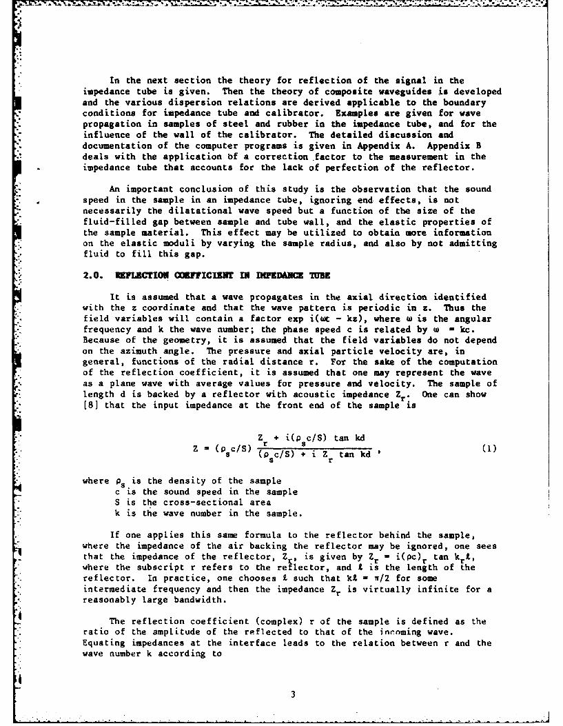
In the next section the theory for reflection of the signal in theimpedance tube is given. Then the theory of composite waveguides is developedand the various dispersion relations are derived applicable to the boundaryconditions for impedance tube and calibrator. Examples are given for wavepropagation in samples of steel and rubber in the impedance tube, and for theinfluence of the wall of the calibrator. The detailed discussion anddocumentation of the computer programs is given in Appendix A. Appendix Bdeals with the application bf a correction .factor to the measurement in theimpedance tube that accounts for the lack of perfection of the reflector.
An important conclusion of this study is the observation that the soundspeed in the sample in an impedance tube, ignoring end effects, is notnecessarily the dilatational wave speed but a function of the size of thefluid-filled gap between sample and tube wall, and the elastic properties ofthe sample material. This effect may be utilized to obtain more informationon the elastic moduli by varying the sample radius, and also by not admittingfluid to fill this gap.
2.0. 1FLECTION OMMFICIENT I I WEDAMN TUBK
It is assumed that a wave propagates in the axial direction identifiedwith the z coordinate and that the wave pattern is periodic in z. Thus thefield variables will contain a factor exp i(ot - kz), where w is the angularfrequency and k the wave number; the phase speed c is related by W - kc.Because of the geometry, it is assumed that the field variables do not dependon the azimuth angle. The pressure and axial particle velocity are, ingeneral, functions of the radial distance r. For the sake of the computationof the reflection coefficient, it is assumed that one may represent the waveas a plane wave with average values for pressure and velocity. The sample oflength d is backed by a reflector with acoustic impedance Zr. One can show[8] that the input impedance at the front end of the sample is
Z + i(Ps c/S) tan kdZ(P C/S)r (1
s (Psc/S) + i Z tan kds, r
where Ps is the density of the samplec is the sound speed in the sampleS is the cross-sectional areak is the wave number in the sample.
If one applies this same formula to the reflector behind the sample,where the impedance of the air backing the reflector may be ignored, one seesthat the impedance of the reflector, Z , is given by Zr - i(pc) r tan krl ,where the subscript r refers to the reflector, and I is the length of thereflector. In practice, one chooses X such that kX - w/2 for someintermediate frequency and then the impedance Zr is virtually infinite for areasonably large bandwidth.
The reflection coefficient (complex) r of the sample is defined as theratio of the amplitude of the reflected to that of the incoming wave.Equating impedances at the interface leads to the relation between r and thewave number k according to
3
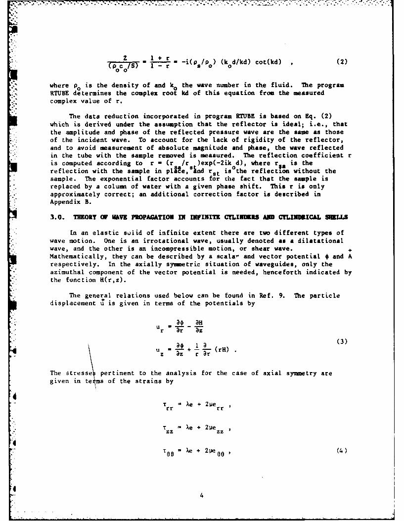
Z I +r(p c ) - + - -i(p /po) (k d/kd) cot(kd) (2)- (PoCo/S) 1 - r '
where pO is the density of and ko the wave number in the fluid. The programRTUBE determines the complex root kd of this equation from the measuredcomplex value of r.
The data reduction incorporated in program RTUBE is based on Eq. (2)which is derived under the assumption that the reflector is ideal; i.e., thatthe amplitude and phase of the reflected pressure wave are the same as thoseof the incident wave. To account for the lack of rigidity of the reflector,
"" and to avoid measurement of absolute magnitude and phase, the wave reflectedin the tube with the sample removed is measured. The reflection coefficient ris computed according to r - (r /r )exp(-2ik d), where roa is thereflection with the sample in ple, nd r s 0 the reflection without the
* sample. The exponential factor accounts for Lhe fact that the sample isreplaced by a column of water with a given phase shift. This r is onlyapproximately correct; an additional correction factor is described in
*i Appendix B.
3.0. THKORY OF WAVK PROPAGATION I FINT CYLIMDiS AND CYLINIMCAL SLLS
In an elastic solid of infinite extent there are two different types ofwave motion. One is an irrotational wave, usually denoted as a dilatational
' wave, and the other is an incompressible motion, or shear wave. +Mathematically, they can be described by a scalar and vector potential * and Arespectively. In the axially symetric situation of waveguides, only theazimuthal component of the vector potential is needed, henceforth indicated by
*,i the function H(r,z).
The general relations used below can be found in Ref. 9. The particledisplacement u is given in terms of the potentials by
ao 3Hur 3r 3z
uz + 7 (rH).
The stresse pertinent to the analysis for the case of axial symmetry aregiven in te ms of the strains by
T Ae + 2perr rr
T Xe + 2 peZZ Zz
i" XS 8' e + 2 p- e_ (4)
!4
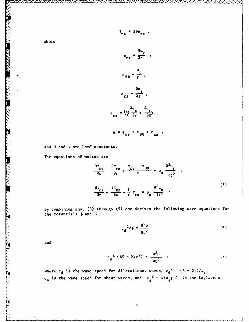
rz rz
whe re
aurerr r '
Ur
e86 r
ezz 3z
3u auz r
rr zz
:-. and Xk and Ii are Lam6 constants.
"The equations of motion are
3}T 3}T T - ^ 3)2urr rz rr 00 r
3Ta 3T3uu5
rzr- r+ -- z -s at
ee - + er +es-Z
By combining Eqs. (3) through (5) one derives the following wave equations for
the potentials o and H
i.C "d2A = -2_ (6)
and
3r2
c 2 (AH -H/r 2 ) ff )H (7)
s 8t2
where cd is the wave speed for dilatational waves, Cd2 ( + 2 t)/ps,
the potentialstheLapaadeH
cw is the wave speed for shear waves, and c s s
5
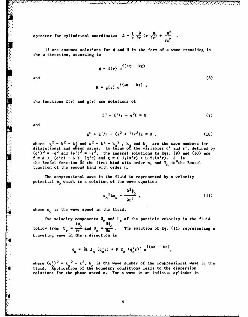
operator for cylindrical coordinates A = (r + - .ri Tr T z2
If one assumes solutions for * and H in the form of a wave traveling in. the z direction, according to
i(wt - kz)
*-f(r) e
and (8)
H- g(r) ei(Wl - kz)
the functions f(r) and g(r) are solutions of
f" + f'/r - q2f 0 (9)
and
+ g'/r - (s2 + I/r2)g =0 , (10)
where q2 k2 - k2 and s2 k 2 - k 2 k and k are the wave numbers fordilatational and sear waves. In tSrms o the variables q' and s', defined by
S(q') 2 =q and (s,)2 - -82, the general solutions to Eqs. (9) and (10) are
f - A J (q'r) + B Y (q'r) and g = C Jl(s'r) + D Y1(s'r). J isthe Bessel function of the first kind with order n, and Yn isnthe Bessel
• function of the second kind with order n.
The compressional wave in the fluid is represented by a velocitypotential €o which is a solution of the wave equation
C2A€° a2 , (11)0 0 t2
where co is the wave speed in the fluid.
The velocity components Ur and Uz of the particle velocity in the fluid
follow from U r - and Uz a . The solution of Eq. (11) representing a
traveling wave in the z direction isa"- i(wt - kz)
0 - [E J (q r) + F Y (qor) J e
where (q')2 - k 2 - k2, k is the wave number of the compressional wave in the
* fluid. ipplicahion of the boundary conditions leads to the dispersionrelations for the phase speed c. For a wave in an infinite cylinder in
6
vacuum, the analysis has been performed by Pochhammer and Chree [10]. Acomprehensive set of calculations of the phase speed based on the Pochhammer-Chree solution were performed by Bancroft [111.
I*4.0. PROPAGATION SPEED OF AXIALLY SYMMETRIC MWES IN COMPOSITE CYLINDERS
The determination of phase speed in composite cylinders is accomplishedby imposing the pertinent boundary conditions on the stresses and particlevelocities derived in Section 3. An overview of the various optior in thecomputer program is presented in Fig. 3.
The physical situation in the impedance tube is represented itOption 1. A solid cylinder is surrounded by a thin layer of fluid d thecenter wall of the tube is assumed to be rigid. For comparison, a outerboundary is considered in Option 2, although this case can hardly t alizedin practice. The calibrator situation is represented by Option 3, where the
influence of a nonrigid wall on the fluid wave speed is evaluated. Options 4and 5 reflect the situation where a soft coating is applied to the inside ofthe calibration tube in order to slow down the wave in the liquid; inOption 4 the coating is cemented to the wall, in Option 5 it is free to movetangentially at the wall. In Option 6 the wave speed in a fluid cylinder withrigid boundary is computed, in Option 7 the wave speed in a fluid cylinderwith free boundary is computed.
/I \ I\
// I
FLU FLUID /
-RIM N FREE /OPTION I OPTION 2
/ //-I Ii I
FLUIDFLUID
SOLID /SOLID
\0\
FIREE N RIGIDCEMENTED
OPTION 3 OPTION 4
O { (N UID OPTION 6
FLUID IGID 0
SOLID ( FLUID IOPTION 7NO
CEMENTEDOPTION 5 FREE
Fig. 3 -Cross section of waveguides in situations correspondingto options in program W#GUIDE.
7
In the real variable program WGUIDE, the variables q', a', and q' may beeither real or imaginary. In order to avoid the necessity of complex0
calculations, the transformations q' + iq; a' + is and q; + iq areapplied whenever imaginary values appear. The Bessel functions aretransformed according to the identities Jo(ix) - I(X), J(ix) - iI(x),
Y (ix) = -K (x), and Y1 (ix) = iK,(x). In(x) and Kn(x) are modified Besselfunctions [?21.
* 4. 1. Wave Speed in Sample in Impedance Tube
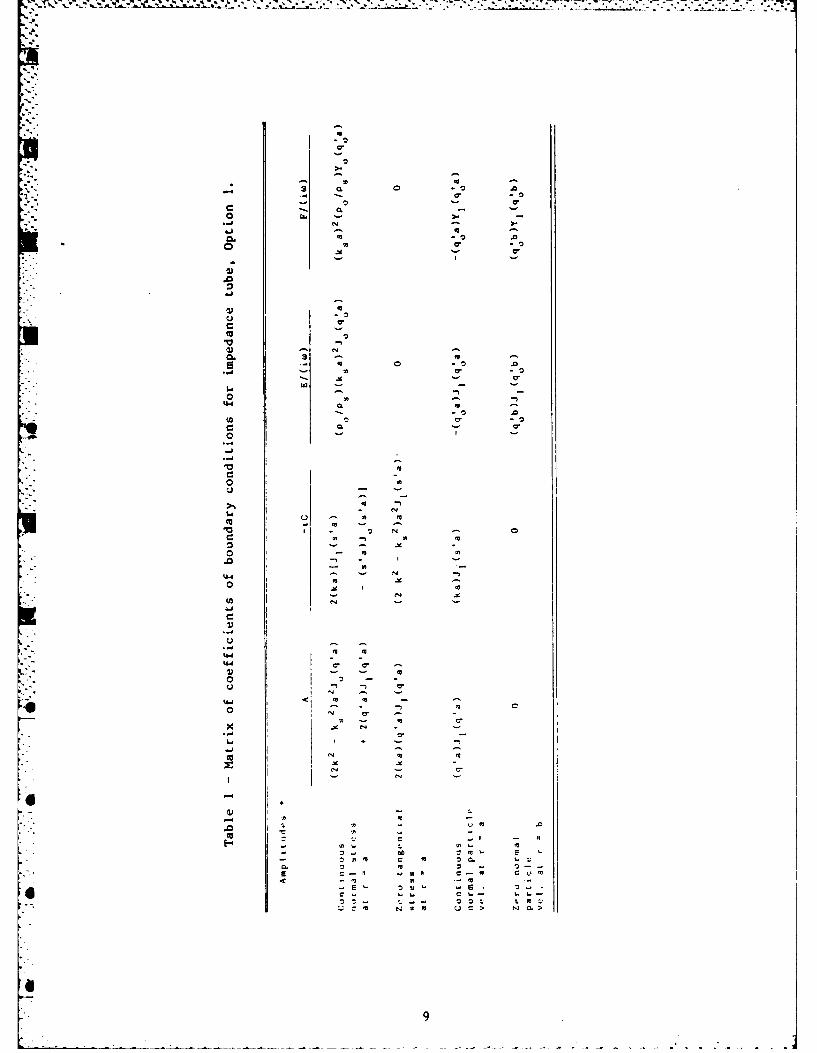
The following set of boundary conditions is applied to the fieldvariables in the solid cylinder and surrounding fluid if the outer wall isrigid (Option 1).
a. The normal stress Trr in the solid is equal to the negative ofthe pressure p in the fluid at the surface r - a, where a is theradius of the cylinder. The pressure follows from
8to2k P 2 Thus p =-Po 11 at r =a.
b. The tangential stress Trz is zero in the solid for r f a.
c. The normal component of the particle velocity is continuous atthe interface between solid and fluid at r - a.
d. The normal component of the particle velocity in the fluid Ur iszero at r - b.
The coefficients of the amplitudes A, C, E, and F may be shown in amatrix, Table 1. Equating the determinant value of this matrix to zero yieldsthe dispersion relation for the wave speed.
If the outer boundary is assumed free (Option 2), the fourth boundarycondition is replaced by one where the pressure in the fluid is zero for
* r = b. The resulting matrix of the coefficients is shown in Table 2.
For the case of the calibrator, one assumes that the fluid cylinder has a
radius a and is bounded by a solid, but not rigid, wall with outer radius b.- The following set of boundary conditions applies to the field variables in
fluid and cylinder wall.
a. The negative value of the pressure p is equal to the normalstress in the solid at r - a.
" b. The tangential stress in the solid is zero at r = a.
c. The normal stress in the solid is zero at r = b.
d. The tangential stress in the solid is zero at r = b.
e. The normal component of the particle velocity in the fluid isequal to that in the solid at r - a.
The resulting coefficient matrix for amplitudes A, B, C, D, and F is shown in'Table 3.
It was desirable to analyze the situation where a soft coating was
aplied to the inside of the calibrator with the purpose of reducing theeffective wave speed in the liquid of the calibrator. If this coating iscemented to the wall, the following boundary conditions apply:
1"
L..
*? -o'. .. * *
.0I
. ". ,
* U
".",
U - A a
* * A I
- t. 0 -
I
-" ' " - - - - - °~ • o- ° - -- . . • • -. -. ° •
Option 4
a. The negative value of the pressure p is equal to the normal stress inthe solid at r - a.
b. The tangential stress in the solid is zero at r = a.
c. The normal component of the velocity is zero at r = b.
d. The tangential component of the particle velocity is zero at r b.
e. The normal component of the particle velocity is continuous at r = a.
The resulting matrix of the coefficients of these boundary conditions isshown in Table 4.
If the coating is not cemented to the wall, but is free to move in atangential direction, condition (d) is replaced by the requirement that thetangential stress in the solid is zero at r - b. The resulting matrix isgiven in Table 5.
15
- a.-
'* e 0 0 .0
o -0
* a
:Lo - a
: 1 -. - -.
- . I
* - #-. a -4
•o a.a a a, U
- ® .,, - -
,-I
o.. a # #
o. ".#4 .4 U
o I -, a-
-. I #4a#
0 - - .6
Empty cylinder
The phase speed in an empty solid cylinder may be readily derived fromthe matrix in Table 2 by omitting the fifth row and fifth column and settingthe determinant value of the remaining 4x4 matrix equal to zero.
Other phase speeds of interest may be obtained. In a fluid column withfree boundaries, the phase speed is given by
Jo(q' a) -0 or (c/c) 2 1/Li - Jom/(koa)2] (12)0 0 o0 0
where m = 1,2,... and Jo,m are the zeros of the J. Bessel function. Thus,there is a cutoff frequency given by
w an c/a (13)
below which no wave propagation is possible in a free fluid cylinder.Similarly, the phase speed of waves in a fluid cylinder bounded by rigid wallsfollows from
(q a)J (q a)- 0 (14)
or
(c/co)2 = 1/[L - j2 m/(koa)21 (15)
where m = 0,i,2,... and Jl,m are the zeros of the Jl Bessel function(including JlO - 0).
4.3. Complex Vave Speed In Sample In Impedance Tube
i4 The measurements in the impedance tube consist of a complex reflectioncoefficient. Thus, it is important to determine the complex wave speed thatis connected with a pair of complex elastic moduli. This is accomplished bythe program IMPED. Its dispersion relation is the same as in WGUIDE option 1,but the roots are found by a complex root finder described in Ref. 13.
45.0. RiSULTS AD DISCUSSION
The original incentive to develop the WGUIDE program was the need todetermine exactly which propagation speed is measured in the impedance tube.It appears to be tacitly assumed that the dilatational speed is the quantity
measured. For instance, in Ref. 14 the sound speed is graphed without furtherqualification; from the text one may infer that it is the dilatational wave
17
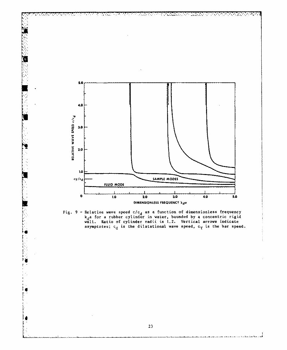
speed. The present analysis shows that it depends on the circumstances as towhat speed applies for the sample in the impedance tube. This is shown in asequence of figures. The first set shows the dispersion relation in a sampleof steel with a density of 7700 kg/in3, Young's modulus 19.5x10¹⁰ Pa,shear modulus 8.3x0 1 0 Pa, Poisson's ratio 0.37 (data from Ref. 15). The tubeis filled with water with density 998 kg/m 3 and wave speed 1481 m/s. Theabscissa kda is a dimensionless measure of the frequency, with kd the wavenumber for the dilatational wave in the solid and a the radius of thecylindrical sample; the ordinate is the ratio of the wave speed to thedilatational wave speed. For large values of kda the wave speed approachesthe Rayleigh wave speed. Figure 4 shows that for a sample in vacuum at lowfrequency the bar speed is approached, as expected. With water in the spacebetween the tube wall and the sample, radii a and b, respectively, the wavespeed in the sample at low frequency increases with decreasing value of b/a asseen in Figs. 5 and 6 and is indistinguishable from the dilatational wavespeed (c/cd 1) for b/a = 1.001, Fig. 7. Notice that there is a "fluid mode"with low propagation speed in addition to various modes determined by thesample. The same behavior is shown by hard rubber as sample material, density1100 kg/m 3, shear modulus 0.1X101 0 Pa, bulk modulus 0.5xlOI0 Pa. Here,however, a thicker layer of fluid is able to constrain the material tomanifest dilatational wave speed than for steel (see Figs. 8 through 10).Even for b/a = 1.2, the speed is close to the dilatational wave speed (Fig. 9)The value for b/a is about 1.03 for the NRL-USRD impedance tube.
S.0
* 4.0-
S-U
3.0 -#A
2! 2.0 -
I- SAMPE MODES
".7.
'0 1.0 2.0 3.0 4.0 S.0
','." DIMENSIONLESS FREOUENCY kda
:Fig. 4 Relative wave speed c/c d as a function of dimensionless frequency!' k~da fo tel linder in vacuum. Vertical arrows indicate
i': asymptotes; c d is the dilatational speed, Cy is bar speed.
-18
5.0
4.0
O 3.0
S2.0
1.0
~SAMPLE MODES
• FLUID MODE
VA
0 o.0 2.0 3. 4.0 S.
DIMENSIONLESS FREOUENCY kdO
Fig. 5 -Relative wave speed c/cd as a function of dimensionless frequency
kda for steel cylinder in water, bounded by a concentric rigidwall. Ratio of the cylinder radii is 1.05. Vertical arrows indi-cate asymptotes; cd is the dilatational speed, c y is the bar speed.
i4
1019
LC"/'d-
5.0-
* 4.0
U
2 .0-
0M 2.0.0304. .
C/d
Fig. 6indReate aveypoed Cd s ah functtiona fed dienioles frequenc
speed.
20
5.0
4.0
o 3.0#ASM
3t
2.o-
1.0cy/cd SAMPLE MODES
FLUID MODEi Ii Ii IiI
0 1.0 2.0 3.0 4.0 5.0
DIMENSIONLESS FREQUENCY kda
Fig. 7 - Relative wave speed c/cd as a function of dimensionless frequencykda for a steel cylinder in water bounded by a concentric rigidwall. Ratio of cylinder radii is 1.001. Vertical arrows indicateasymptotes; dd is the dilatational wave speed, cy is the bar speed.
21
S.0
4.0
CL 3.0
LU
> 2.0. -.
1.0
Cy lcd-
0 1 A I I I I1.0 2.0 3.0 4.0 5.0
DIMENSIONLESS FREQUENCY kda
Fig. 8 - Relative wave speed c/cd as a function of dimensionless frequencykda for a rubber cylinder in vacuum. Vertical arrows indicateasymptotes; cd is the dilatational wave speed, Cy is the bar speed.
22
F:.0
4.0
3.0
.03.03.-
I"cy/cd SAMPLEMOE. FLUID MODE
20 i.0 2.0 3.0 4.0 .0
,+i DIMENSIONLESS FREOUENCY kda
'iFig. 9 -Relative wave speed c/c d as a function of dimensionless frequency
[++ kda for a rubber cylinder in water, bounded by a concentric rigid+ wall. Ratio of cylinder radii is 1.2. Vertical arrows indicate
I Q asymptotes; c d is the dilatational wave speed, cy is the bar speed.
I-3
[---l"L
lto
CY/Cd
' 7
5.0
4.0
-
1.0
cy/c d SAMPLE MOVES
"FLUID MODE
1.0 2.0 3.0 4.0 5.0
DIMENSIONLESS FREQUENCY kda
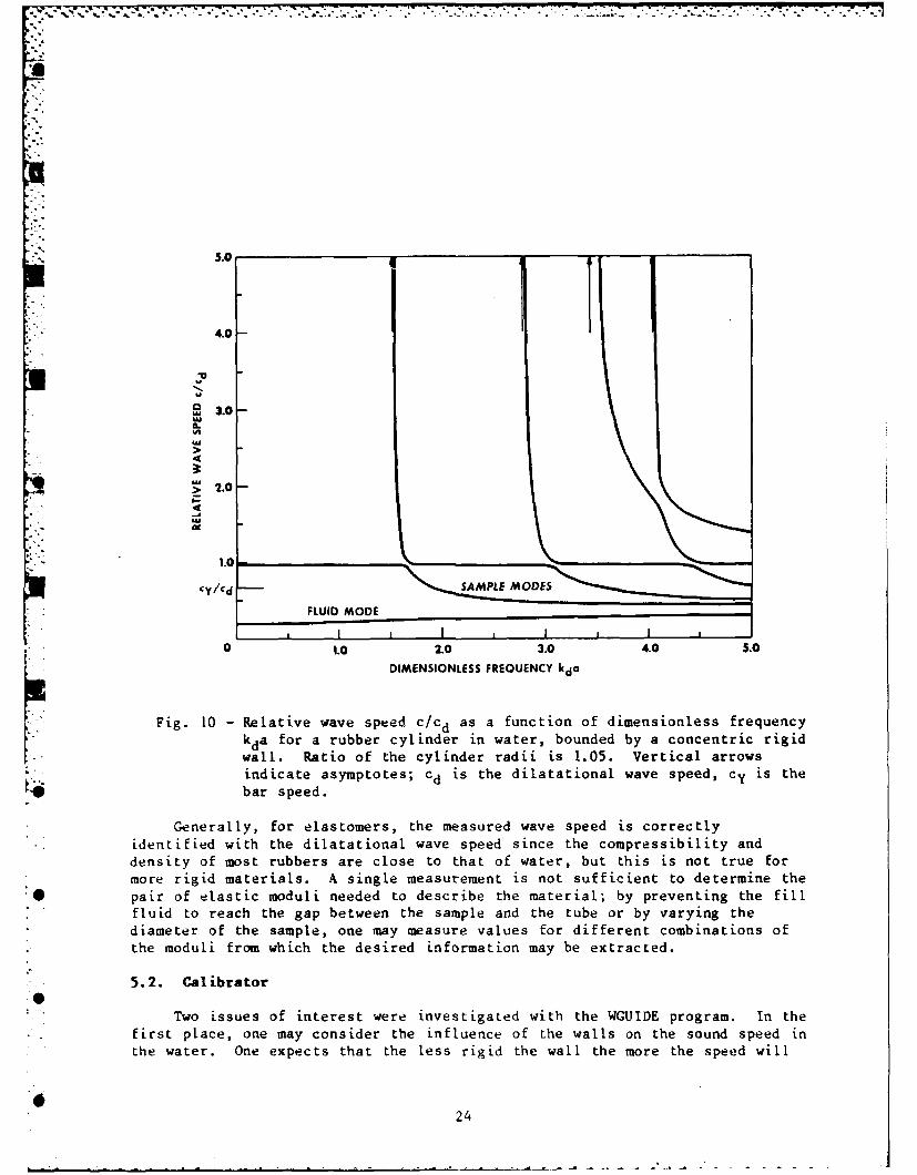
Fig. 10 - Relative wave speed c/cd as a function of dimensionless frequencykda for a rubber cylinder in water, bounded by a concentric rigidwall. Ratio of the cylinder radii is 1.05. Vertical arrowsindicate asymptotes; cd is the dilatational wave speed, Cy is the
0O bar speed.
Generally, for elastomers, the measured wave speed is correctly
identified with the dilatational wave speed since the compressibility anddensity of most rubbers are close to that of water, but this is not true formore rigid materials. A single measurement is not sufficient to determine the
*O pair of elastic moduli needed to describe the material; by preventing the fillfluid to reach the gap between the sample and the tube or by varying thediameter of the sample, one may measure values for different combinations ofthe moduli from which the desired information may be extracted.
5.2. Calibrator
Two issues of interest were investigated with the WGUIDE program. In thefirst place, one may consider the influence of the walls on the sound speed inthe water. One expects that the less rigid the wall the more the speed will
24
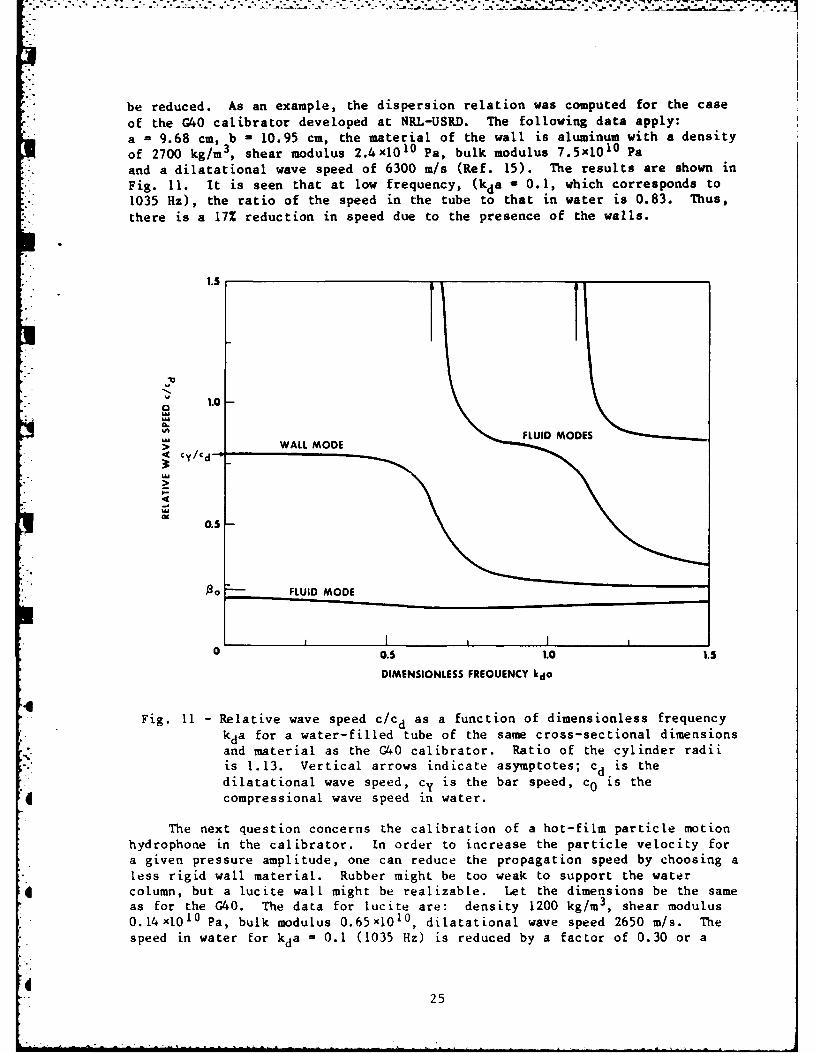
be reduced. As an example, the dispersion relation was computed for the caseof the G40 calibrator developed at NRL-USRD. The following data apply:a 9.68 cm, b - 10.95 cm, the material of the wall is aluminum with a density
of 2700 kg/m 3, shear modulus 2.4x10 10 Pa, bulk modulus 7.5x10 10 Pa
and a dilatational wave speed of 6300 m/s (Ref. 15). The results are shown inFig. 11. It is seen that at low frequency, (kda - 0.1, which corresponds to1035 Hz), the ratio of the speed in the tube to that in water is 0.83. Thus,
there is a 17% reduction in speed due to the presence of the walls.
1.5
- -U
1.0-
FLUID MOE>WALL MODE• 4 Cy/€ d j
0.5
S -- FLUID MODE
0 0.5 1.0 1.5
DIMENSIONLESS FREQUENCY kda
.4Fig. 11 - Relative wave speed c/cd as a function of dimensionless frequency
kda for a water-filled tube of the same cross-sectional dimensionsand material as the G40 calibrator. Ratio of the cylinder radii
is 1.13. Vertical arrows indicate asymptotes; cd is thedilatational wave speed, cy is the bar speed, co is the
"4 compressional wave speed in water.
The next question concerns the calibration of a hot-film particle motion
hydrophone in the calibrator. In order to increase the particle velocity for
a given pressure amplitude, one can reduce the propagation speed by choosing a
less rigid wall material. Rubber might be too weak to support the water
* column, but a lucite wall might be realizable. Let the dimensions be the sameas for the G40. The data for lucite are: density 1200 kg/m 3 , shear modulus
speed in water for kda = 0.1 (1035 Hz) is reduced by a factor of 0.30 or a
225
speed of 440 m/s. Another possible way to reduce the wave speed in the tubeis to insert a concentric layer of a suitable material inside the tube. Theparameters influencing the reduction in wave speed are the elastic constants,density, and the ratio b/a. The results for a number of materials are shownin Table 6. Only polyethylene gives a sizable reduction in wave speed: afactor of 2. The data for glass, lead, rubber, and lucite were taken fromRef. 15, the data for polyethylene and polystyrene from Ref. 16.
Table 6 - Reduction in wave speed for various wall coatings in G40calibrator (Frequency is 1035 Hz, a = 7.0 cm, b = 9.8 cm).
Recent theoretical and experimental work in sound propagation in pipeswith acoustic impedance comparable to that in water is found in Refs. 17 and18.
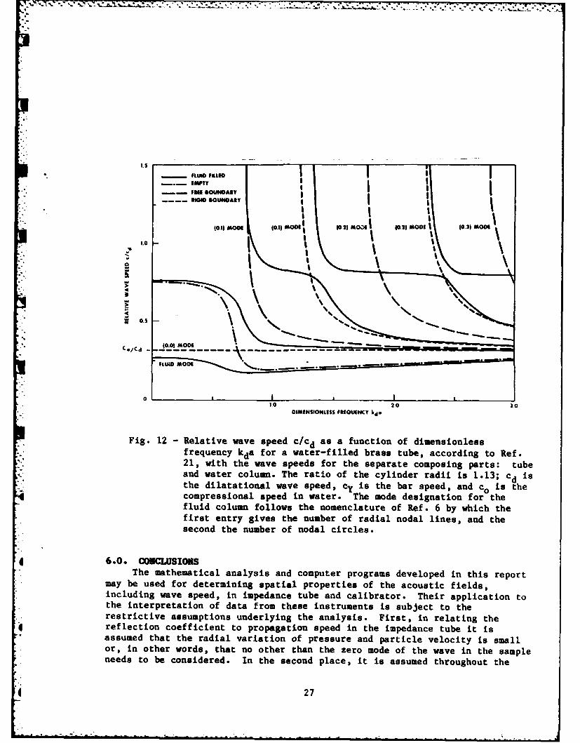
For comparison with the literature, Fig. 12 shows the dispersion relationin a water-filled tube in addition to the curves for an empty tube, and awater column that has a rigid boundary and one that has a free boundary. Thematerial of the wall is brass, as in Ref. 19, the results of which arereproduced in Ref. 20. The ratio of cylinder radii was chosen accordingly,b/a = 1.13. The material constants for brass are those given in Ref. 15.P = 8500 kg/m 3, G/K - 0.279, and cd - 4700 m/s. The "longitudinal wavespeed" is given in Ref. 19 as 3590 r/s which actually is closer to the bar
6 speed, 3500 m/s. according to Ref 16. The results in Fig. 12 show that thewave speed approaches the bar speed (subscript Y) for small kda, indisagreement with Ref. 19 but in accordance with Ref. 21.
4
0 26
NF * I I
RIMl OUNOARY £I- - " tII,SI I
I\ %\\
(Oild MOO (0.01 MOOD0E) M ~ 0.)M O (.) M O
1.0 2.0
Fig. 12 -Relative wave speed c/c d as a function of dimensionless
frequency kda for a water-filled brass tube, according to Ref.21, with the wave speeds for the separate composing parts: tubeand water colun. The ratio of the cylinder radii is 1.13; c d isthe dilatational wave speed, cy is the bar speedI and co is thecompressional speed in water. The mode designation forothefluid column follows the nomenclature of Ref. 6 by which thefirst entry gives the number of radial nodal lines, and thesecond the number of nodal circles.
6.0. CONCLUSIONS
The mathematical analysis and computer programs developed in this reportmay be used for determining spatial properties of the acoustic fields,including wave speed, in impedance tube and calibrator. Their application tothe interpretation of data from these insrufents is subject to theresfrictive assumptions underlying the analysis. First, in relating thereflec2ion coefficient to propagation speed in the impedance tube it isassumed that the radial variation of pressure and particle velocity is smallor, in other words, that no other shan thC is the of the wave in the sampleneeds to be considered. In he second place, i is assumed throughout the
| 27
.-. 7
computation of wave speeds that the composite cylinders are infinite in the
axial direction. This ignores the influence of the unavoidable termination ina finite cylinder on the wave pattern in the waveguide. The experimentalefforts to terminate the waveguides by rigid reflectors or other idealizeddevices can ipso facto be only approximately successful. It is assumed thatthe idealization implied by the model of infinite cylinders will be moreclosely approached the larger the ratio of length to diameter of the sections
of the waveguide.
Keeping this restriction in mind, one may conclude that it is notnecessarily true that the wave speed measured by the impedance tube is thedilatational speed. It is rather a function of the thickness of the fluid-filled gap between sample and wall, in relation to the elastic properties of
the sample material that determines the proper wave speed. As a consequence,one may measure different wave speeds by changing the radius of the sample, orby removing the fluid from the gap. Experimental study will have to decide inhow far the finite length of the sample would interfere with theinterpretation of the data.
ERFERENCES
1. G. H. Sabin, "Acoustic Impedance Measurements at High HydrostaticPressures," J. Acoust. Soc. Am. 40, 1345-1353 (1966).
2. 1. D. Groves Jr., "Twenty Years of Underwater ElectroacousticStandards," NRL Report 7735, 1974, pp. 61-65.
3. G. D. Hugus III and I. D. Groves, Jr., "Hydrophone Calibrator forShipboard Use," J. Acoust. Soc. Am. 56, 70-74, (1974).
4. S. heatty and J. F. Prandc-ii, "Underwater Sound Transducer CalibrationF.cility for the 10- t, 4000-Hz Frequency Range at Hydrostatic Pressure
to 10,000 psic," NRL Report 6965, August 1969.
5. H. J. llebert and L P. Browder, "Underwater Sound Transducer CalibrationSystem f.-'r the 0.3- to 2000-Hz FreqUency Range at Hydrostatic Pressureto 6.89 MPa.," NRL Report 7502, October 1972.
6. M. Redwood, MochaniczZ Waveguides, Pergamon Press, New York, 1960.7. J. Miklowitz The. 7, eor ,j
~t, aeory of Ela't-c Waves ani Waveguides, North Holland,
Arist :rdam. 1978.
8. L. E. lin ' I-r aji %. R. -r v Fun'xen'?,2 of Acoustics, 2nd ed, Wiley,New York, 1962, p. 201.
9. 1. S. Sokolnikof. , t1'th7at l'a Theo.y .i1aeticity, McGraw Hill, 1956,pp. 183-184.
10. Rcf. 6', ClIapt)0r - .
11. D. Bancroft, "rh, Vil(city of 1 n,)nitudiai 'Javs in Cylindrical Bars,"Phys Rev. 59, 583-593
12. N. W. McLachlan, Bessel Functions for Engineee, Oxford UniversityPress, 1955.
13. P. S. Dubbelday, "Complex Root-Finding Program with Application to theDispersion Relation of Waves Propagating in a Fluid Plate," NRLMemorandum Report 4559, November 1981.
14. J. L. Lastinger and I. D. Groves, "Speed of Sound in Four Elastomers,"NRL Memorandum Report 2363, December 1971.
15. Ref. 8, p. 502.
16. H. L. Anderson editor, "Physics Vade Mecum," American Institute ofPhysics, NY (1981), p. 60.
17. R. A. Skop, "Sound Propagation Through Liquids in Viscoelastic CircularCylinders", Shock-Vib. Bull. 51 Part 1, 217-223 (May 1981).
18. N. P. Horne and R. J. Hansen, "Sound propagation in a pipe containing aliquid of comparable acoustic impedance," J. Acoust. Soc. Am. 71, 14001405 (1982).
19. T. C. Lin and G. W. Morgan, "Wave propagation through fluid contained ina cylindrical elastic shell", J. Acoust. Soc. Am. 28, 1165-1176 (1956).
20. Ref. 6, p. 245.
21. 1. Mirsky and G. Herrmann, "Axially Symmetric Motions of ThickCylindrical Shells," J. App[. Mech. 25, 97-102 (1958).
29
(BLANK PAGE)
0 30
hMUUDiX A
Computer Program
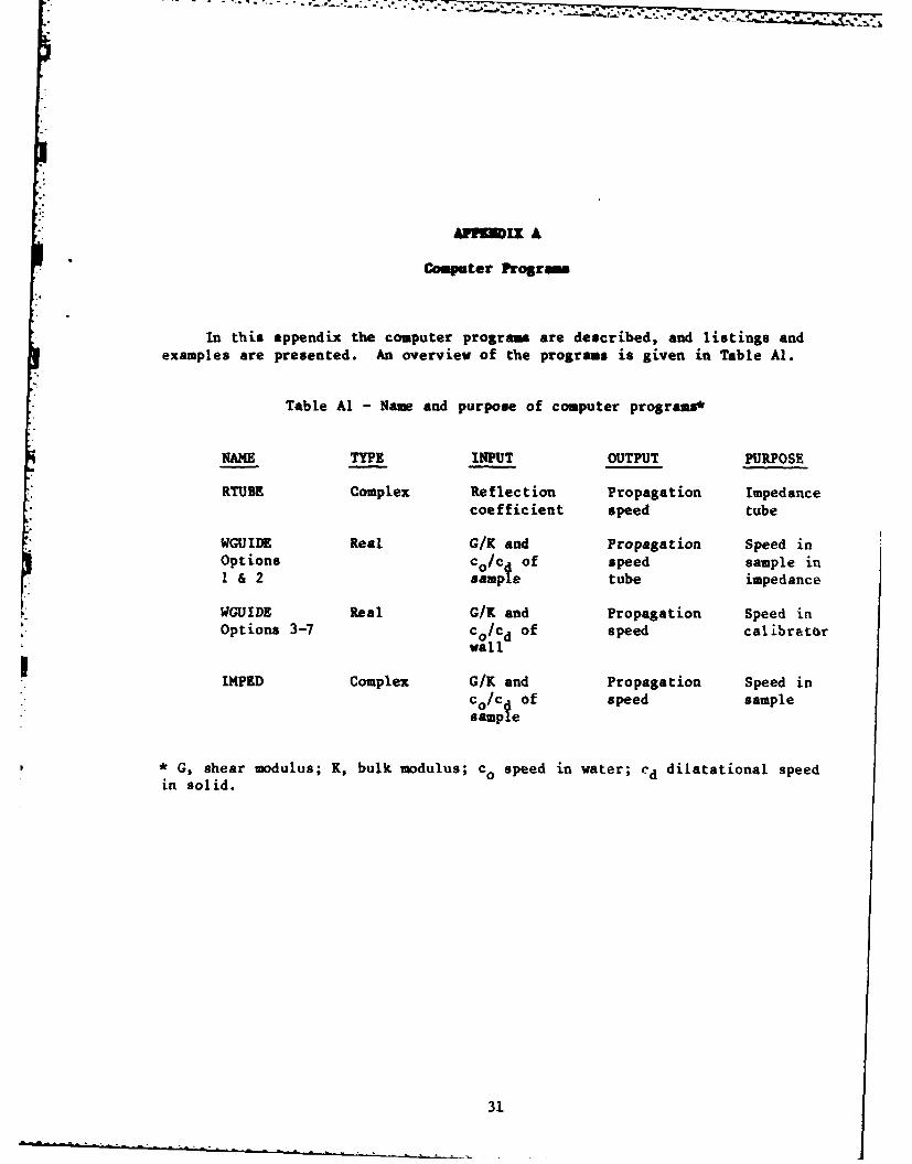
In this appendix the computer programs are described, and listings andexamples are presented. An overview of the programs is given in Table Al.
WGUIDE Real G/K and Propagation Speed inOptions co/c of speed sample inI & 2 sampe tube impedance
WGUIDE Real G/K and Propagation Speed inOptions 3-7 Co/ed of speed calibrator
wall
P IMPED Complex G/K and Propagation Speed inCo/c of speed samplesample
* G, shear modulus; K, bulk modulus; co speed in water; cd dilatational speedin solid.
31
DESCIPTION O PROGRAM &U
The computer program RTUBE determines numerical values for the soundspeed and attenuation of a sample in the acoustic impedance tube. The inputto the program consists of the measured values of the amplitude and phase ofthe signal reflected by the sample and of the signal reflected without asample in the tube, indicated by "standard". The program is written inFORTRAN IV and should run on any computer that accepts this language.
There are two major parts in RTUBE. First a real-valued seed or startingvalue for the sound speed is computed from the reactive part of the acoustic
* impedance.* This seed is entered into subroutine R0819, which contains the*logic for the complex root search. The function, the roots of which are
sought, is contained in subroutine DS.**
The real root finder determines the real part of (kd) corresponding tothe reactive part X of the impedance Z in Eq. (2). according to the relation
",. X kdkd -(Ps /p) cot(kd) (Al)
0
Obviously, there is an infinite number of roots kd of this equation and oneneeds circumstantial evidence about the propagation speed in order to choosethe correct one. In the iterative procedure used here, it is necessary toevaluate an inverse cotangent function which involves choosing the properbranch.
The propagation speed in the water is computed for a given temperatureand pressure. The density of the fluid is 1.034 g/cm 3, applicable to theglycol water mixture used in the experiment. For a different fill-fluid, this
*- number should be changed accordingly.
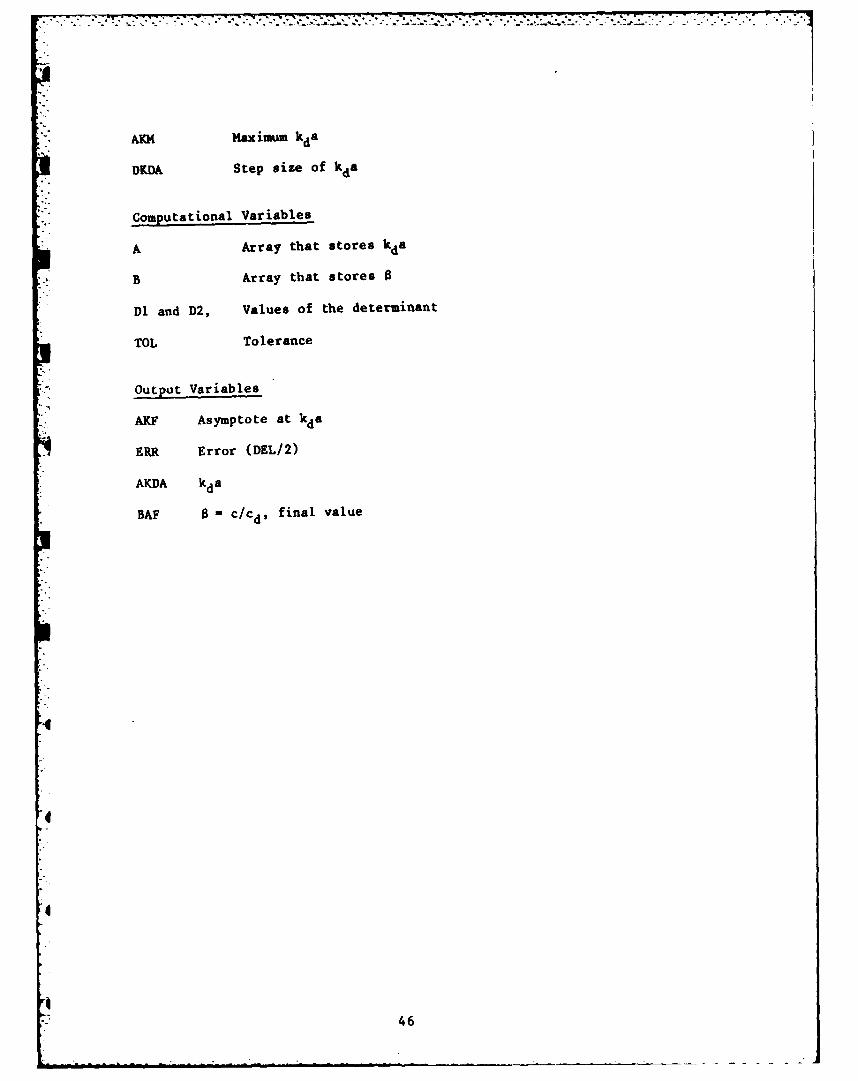
Important Variables in RTUBE
Input Variables
AMAX Maximum frequency (Hz)
AMIN Minimum frequency (Hz)
N3eDENS P., density of material (g/cm3)
PRES p, pressuie (MPa)
* C.M. Ruggiero, "Solution of Transcendental and Algebraic Equations with
Application to Wave Propagation in Elastic Plates," NRL Memorandum ReportS 4449, November 1981.
.** P.S. Dubbelday, "Complex Root-Finding Program with Application to theDispersion Relation of Waves Propagating in a Fluid Plate," NRL Memorandum4559, November 1981.
32
PSA Phase of sample
PST Phase of standard
STEP Step size
TEMP Temperature (C)
THICK Length of sample (cm)
VSA Voltage of sample
VST Voltage of standard
Computational Variables
A ( 0/ps)(kd)
ANS = ANSI Counter, same as Z plus branch correction (+nr)
DIFF Difference of last approximation and currentapproximation
E Phase difference (in radians for signals with and
without sample).
G Phase difference corrected for absence of sample
I and X Slopes computed at seed
J Tolerance of relative error in root
il Number of frequencies
K Counter
M Reactance
N Resistance
[ Q 2 kod, ko is the wave number in water.
4 U Number used in slope computation
V Absolute value of reflection coefficient
W Wave speed in water corrected for ambient temperature
and pressure
Y cot(kd)
3[.
Output variables
AMGA Attenuation (Np/m)
FREQ Frequency (Hz)
SS Sound speed (r/s)
Major Computation Blocks in R3UB, m0819
Descriptions of the major computation blocks in RTUBE are as follows:
C THIS PROGRAM COMPUTES THE SOUND SPEED AND ATTENUATIONc OF THE IMPEDANCE TUBE WHEN THE VOLTAGE OF THE SAMPLE ANDC THE VOLTAGE OF THE STANDARDPTHE PHASE OF THE SAMPLE AND THEc PHASE OF THE STANDARD ARE MEASURED.CC SUBROUTINES USED:C R0819C DSC
0001 REAL MPNPIPJPLYDAT(599)-)002 WRITE(5vlO)0003 10 FORMAT(' ENTER PRESSURE(MPA)PLENOTH(CM),TEMP(C)PDENSITY(G) '
0004 READ( 5,20)PRE STHICKTEMPDENS0005 20 FORMAT(4FI0.0)0006 THICK=THICK/1000007 ZNOT=2.50009 P1=0-)009 ANS1=-100000010 K=l0011 WRITE(5y2l)0012 21 FORMAT(/P' ENTER FREQUENCY (MINYMAXPSTEP) '
0044 IF (AE'S(I) .LE. AES(X))ASSIGN 100 TO JOB'0045 GO TO JOB'0046 95 Y=A*COS(ZNOT+FPI*3,14159 )/SIN(ZNOT+FI*3.14159)0047 ZY(M0048 IF(K .GT. 1000)ASSIGN 100 TO JOB'0049 GO TO 1100050 100 H=-M*(ZNOT+F'I*3.14159)/A0051 Z-ACOS(H/SORT(1+H**2))0052 IFCK ,GT. 1000)ASSIGN 95 TO JOB'0053 110 DIFF=ZNOT-Z0)054 IF(AE'S(DIFF *LE. J) GO TO 2000055 ZNOT=Z0056 K=K+l-)057 IF(K .GT. 1001)ZNOT=ANS10058 IF (K ,GT. 1001)K-100019 GOTO JOB4-.060 200 ANS=Z+PI*3.14159
0037 KUP=00038 KDOWNmO0039 SIGNUAIMAG(F1)*REAL(F2)-REAL(FI)*AIMAG(F2)0040 IF(8ION)71v72p730041 71 FH1=-1.0042 G0 TO 740043 72 WRITE(59302) SIGN0044 302 FORMAT C LEFT-RIGHT SIGHN 'iEl2S5)0045 GO TO 920046 73 FH1-1.0047 74 DELN.FNI*DEL0048 75 Z1=ZI+DELH0049 Z2=Z2+DELH0050 FIwDS(ZI)0051 F2=D8(Z2)0052 SISNsAIMAG(F1 )*REAL(F2)-AIMAG(F2)*REAL(F1)0053 IF (SIGN) 81i82P930054 91 FH2--1.0055 KL=KL+10056 IF (KAM-KL) 99999t840057 99 WRITE(5Y310)0058 310 FORMAT C EXIT LEFT')0059 GO TO 100
0060 82 GO TO 920061 83 FH2 - 1.0062 KR=KR+10063 IF(KAN-KR) 98,99,840064 98 WRITE (5,311)0065 311 FORMAT(' EXIT RIGHT')0066 00 TO 1000067 84 IF (FN1*FH2) 92p75,750068 92 Z4=(ZI+Z2)/2.+DEL
D' WRITE (5,886) KRKLD886 FORMAT C KR-'v14v' KL='P14)
0069 KR=O0070 IL00071 Z3=(Z1+Z2)/2.-DEL0072 F3=DS(Z3)0073 F4=DS(Z4)0074 SIGN=AIMAG(F3)$REAL(F4)-AIMAG(F4)*REAL(F3)0075 IF (SIGN) 10l110291030076 101 FV1=1.0077 G0 TO 1040078 102 WRITE (50304) SIGN0079 60 TO 1220080 103 FV1=-1.0081 104 DELV-FVI*DEL0082 105 Z4=Z4+AISDELY0083 Z3=Z3+AI*DELV
0124 RHO=RHO+RHM/ANR0125 NRV=NRV+I0126 GO TO 700127 145 WRITE (5,173)FREG0128 173 FORMAT(/,' SOUND SPEED AND ATTENUATION FOR FREG =: ',F6.0)0129 SS=(2*3.14159FREQ)/REGA
" 0130 WRITE (5,174)SS,ABS(AMGA)
0131 174 FORMAT(2E15.5)0132 10 CONTINUE
0133 CLOSE(UNIT=1)
" 0134 100 END
04
0
"0
" 40
- - 7 -77 S - ;L.&,t-77 -
0001 FUNCTION DS(Z)
CC THIS IS A SPECIFIC FUNCTION TO BE CALCULATED WITHC COMPLEX ROOTFINDER. THE COMPLEX ARGUMENT IS Z.CC NOTEC ALL DATA IS PASSED IN COMMON STATEMENT
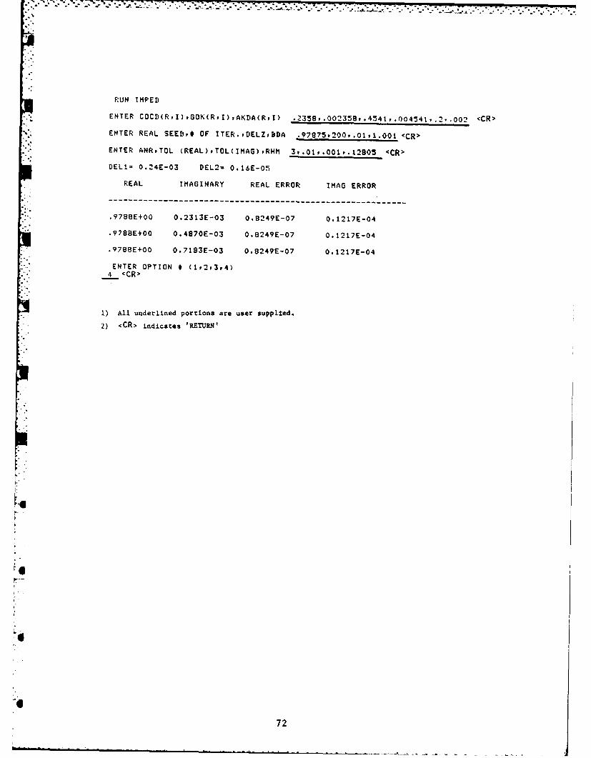
ENTER VOLT. STAND.,VOLT. SAMF', PHASE STAND.,FHASE SAMF.339,.242f358.36-.,79 <CR>
4 REAL SEED REACTANCE=, RESISTANCE= 5.72622 1.75329 0.75410
Iit 42
SOUND SPEED AND AT TENUA T!CN FOR FFCEO 4000.O. 13677E+04 0,45141E+00
SOUND SPEED AND ATTENUATION FOR FREO 5000.
0.13658E+04 O.60050E00
SOUND SPEED AND ATTENUATION FOR FRE= 6000.
0.13943E+04 O.88003E4O0
SOUND SFEED ANI, ,.TfEUAT:UN FOR FREO_ 7000.O. 14196E D4 0. 1; 34 +01
SOUND S'EEE ANI ',T TN,;H ON FOk FREO= 8000.0 .1425!E*,. +.:4:z -,1
.OUND SPEEr' AN! ATENUAT'ON FOR PREG) 9000.O. 14290E * ). I C29E+01
SOUND SPEED , N' 4T'ENUAT!ON FOR FRE: 10000.". 14401E+04 ,'.19, O1 E+0
SOUND SFEED AND' T -ENJA-21 FO. FREG 11000.O .I 429E'*04 O. 1!.798E,01
i. All underlined p)rtions are user supplied.
2) <CR> indiLates 'RETJRN'
I.'43
09SCRIPTILOR OF incM WGUDR
The program WGUIDE computes the speed of axially symmetric wavespropagating along the axial direction in composite infinite cylindrical wave-
- guides, given the values of the ratio of shear modulus and bulk modulus of thesolid and the ratio of the propagation speed in the fluid to the dilatationalwave speed in the solid. To facilitate tracing the complete graph for thedispersion relation, including higher modes, two methods of scanning arepossible. In the first one, the dimensionless frequency kda (abscissa) isfixed and the program searches for all relative wave speeds (ordinate) betweentwo limits. In the other method, the program steps through increasing ordecreasing values for the dimensionless frequency and finds the smallest valuefor the relative wave speed that falls between limits, chosen such that thedesired branch is bracketed. It is also possible to determine the verticalasymptotes. The application of the program is twofold: firstly, the program
* computes the wave speed in the sample Inside an impedance tube which isassumed to be rigid and separated from the tube wall by a concentric layer offluid; secondly, one may apply the program to assess the influence ofnonrigidity of the wall for inertial calibrators.
The main program calls subroutine FUNC for Option numbers 1 through 5.FUNC, in turn, calls subroutine D13 which contains the impedance tubedispersion elation, for Options 1 and 2. Number 1 assumes that the impedancetube wall is rigid, number 2 (rather unrealistically) assumes a free outerboundary. For Option numbers 3, 4, and 5, FUNC calls subroutine CALIB, whichcontains the dispersion relations for the inertial calibrator arrangement.Number 3 is for an elastic tube, fluid-filled or empty; number 4 is for arigid tube with inner coating cemented to the wall; and number 5 is for arigid tube with inner coating free to move tangentially with respect to thewall. If the Option number is 6 or 7, the main program calls subroutineFLUID; for number 6, it computes the wave speed for a fluid tube with rigidboundary. Note that the zero order is the compressional wave speed in thefluid. For the number 7, the wave speed in a fluid with free boundary (inthis case there is a low-frequency cut-off) is calculated.
The program computes the location of vertical asymptotes by entering anegative value of AKDA. In Option 1, entering a negative value fo RHH willprompt the computation of the wave speed in a solid cylinder in vacuum(indicated by '*VACUUM TUBE" in the listing and printout). In Option 3,setting RHM equal to 0 will result in the computation of the wave speed in an
* empty cylindrical shell, indicated by "EMPTY TUBE" in print-out.
The Bessel function subroutines are documented in: System/360 Scientificsubroutine Package Version II (c), International Business Machines Corporation1966, 1967, 1968, White Plains, NY, Section - Special Operations andFunctions, 363 - 367 (copies of these subroutines will not be foundin this report; but the user may implement the needed Bessel function routinesfrom the program library). Subroutine DET computes the determinant value of a
* matrix. The various results are stored by calling subroutine FILE, which is, prompted by choosing Option number 9. The values of y - cy/c
c /C, R c R/C, B° 0 Co/cd, and the asymptotes are als stored in as s doR R
44
file separate from the dispersion results in order to discriminate betweenthem. They can, however, appear on the same graph by running a plottingprogram named PLOTTER.*
FORTRAN Variable Names for WGUIDK
Input Variables
KB: Option number determining mode of operationI Sample !a fluld tube with rigid boundary
= 2 Sample in fluid tube with free boundary= 3 Fluid-filled elastic tube or empty tube= 4 Fluid-filled coated rigid tube (cemented)= 5 Fluid-filled coated rigid tube (not cemented)= 6 Fluid tube with rigid boundary= 7 Fluid tube with free boundary
GOK (G/K) ratio of shear modulus to bulk modulus
COCD (Co/cd) ratio of wave speed in fluid to dilatationalwave speed in solid
RHM (p /ps) ratio of fluid density to density of solid; negativevalue for solid cylinder in vacuum; zero for empty calibrator
AKDA (kda) dimensionless wave number of dilatational waves(ia
k ari c d
B1 or BAM Minimum (kda if asymptote option, 8 otherwise)
.2 Maximum (kd:1 if asymptote option, otherwise)
DB or DEL Step size of (kda if asymptote option, 8 otherwise)
KO: Return option numberI = program returns to entering input option number2 program returns to entering GOK
= 3 program returns to entering COCD4 program rcturna to ertering RHM5 prog L returus to et.ering MIN, MAX, STEP (Y value)0 7,r(ru r tv-ns r - entering BDAI 7 rc,n rtrs to entering AKDA
u )Wogram r'tur,-s to entering MIN, MAX, STEP (X value)=9 st.)ru dat i
C WGUIDEC WRITTEN BY P. DUBBELDAY AND T. RUGGIEROCC THE PURPOSE OF THIS PROGRAM IS TO CALCULATE THE SPEEDC OF AXIAL WAVES IN CYLINDRICAL WAVE GUIDES.CC C SUBROUTINES: BESJBESYBESKDETFILEFUNCINUEC IO,DI3,CALIBFLUIDC
0001 REAL A(500)uB(500)0002 COMMON AKAAKDABAMSPACCtCOCDBDARHMpKByAA0003 K9=00004 110 WRITE(5,120)0005 120 FORMAT(' ENTER * CORRESPONDING TO OPTION DESIRED',
1/9'(1) SAMPLE IN FLUID TUBE WITH RIGID BOUNDARY',2/,'(2) SAMPLE IN FLUID TUBE WITH FREE BOUNPARY',3/p'(3) FLUID FILLED ELASTIC TUBE, OR EMPTY TUBE',4/,'(4) FLUID FILLED COATED RIGID TUBE (CEMENTED)',5/,'(5) FLUID FILLED COATED RIGID TUBE (NOT CEMENTED)',6/p'(6) FLUID TUBE WITH RIGID BOUNDARY',7/v'(7) FLUID TUBE WITH FREE BOUNDARY')
0047 240 FORMAT (/,'$ENTER MINMAXSTEP (VERTICAL SCAN) 1)
0048 250 READ (5,260) BID2,DB
0049 260 FORMAT(3E15.0)0050 IF(K9 .EO. i)GOTO 300
0051 270 WRITE (5,280)0052 280 FORMAT (/,'$ENTER RATIO OF TUBE TO SAMPLE RADIUS (B/A)
0053 READ (5,170) BDA
0054 TYPE *,
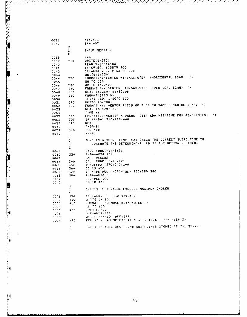
0055 290 FORMAT(/,'$ENTER X VALUE (SET KDA NEGATIVE FOR ASYMPTOTES) )
0056 300 IF (AKDA) 310,440,440
0057 310 KO=8
0058 AKtDA=B1
0059 320 DEL =DB
0060 N=N+1CC FUNC IS A SUBROUTINE THAT CALLS THE CORRECT SUBROUTINE TO
C EVALUATE THE DETERMINANT. KB IS THE OPTION DESIRED.
C
0061 CALL FUNC(-1,KBD1)
0062 330 AKDA=AKDA +DEL
0063 CALL DECLAR
0064 340 CALL FUNC(-1,KBD2)
0065 350 IF(D1*D2) 370,540,390
0066 360 00 TO 620
0067 370 IF (ABS(DEL/AKDA)-TOL) 420,380,380
.69 320 AKDA=AKDA-DEL
2069 DEL=DEL/10.$07 GO TO 330
CCtECh S :F VALJE EXCEEDS MAXIMUM CHOSEN
r
$071 390 IF (,N0A-B$: fl0,400,40010-2 400 Wr!TEI ,410
'I$x 40 0MAT NO MORE ASYMPTOTES '
,774 C 'q 62)
0175 420 L 2Q070 .A, F:.A A-ESR
., ITC ',,430) AKFERR
007f 3 71 F( T , AS'MPTOTE AT X = ,FiO.5,' +/- ',E9.3)
" "'-E A .'TOTE ARE FOUNI. AND POINTS STORED AT Y=1.2591.5
V 49
0079 A(N) =AKF
0080 B(N)=1.250081 N=N+10082 A(N)=AKF0083 B(N)=1.50084 GO TO 3200085 440 SAM=91
*0086 450 DEL=DB0087 N=N+l0088 CALL FUNC(BAMpKBwDl)0089 460 BAM-BAM+DEL0090 CALL DECLAR0091 470 CALL FUNC(BAMFKBYD2)0092 480 IF (DI*D2) 490P540,5100093 490 IF (ABS(DEL/E4AM)-TOL) 560,500,5000094 500 DAM-BAM-DEL0095 DEL=DEL/10.0096 GO TO 4600097 510 IF (BAM-B2) 460i520v5200098 520 WRITE (57530)
*0099 530 FORMAT (' NO MORE ROOTS')0100 GO TO 620
CC PRINTED WHEN EITHER DETERMINANT IS EQUALTO ZERO
0101 540 WRITE (5t550)0102 550 FORMAT (' D1*D2ZERO')0103 GO TO 6200104 560 ERR=DEL/2.0105 BAF=BAM-ERR0106 570 IF(KO .NE. 7)80 TO 6000107 580 WRITE (5v590) BAFPERR
*0108 590 FORMAT(' Y = 'FF10.5p' ERROR ='PE9.20109 A(N)=AKDA0110 BCN)=BAF0111 GO TO 4500112 600 WRITE (59610) AKDAPBAFiERR0113 610 FORMAT(' X ='PF1O.5t' Y a 'PF10.5p' ERROR ='PE9.3)0114 A(N)=AKDA0115 B(N)-BAF0116 AKDA=AKDA+DKDA0117 IF (CAKM-AKDA)*DKDA) 620t440,4400118 620 K9=1
C TO RECYCLE SACK OR EXIT CHOSE OPTION0119 WRITE(59630)0120 630 FORMAT(/Y' ENTER # CORRESPONDING TO CHANGE
1/p' 1) OPTION'2/v' 2) SHEAR M ODULUS/SULK MODULUS (G/K)3/v' 3) SPEED IN FLUID/SPEED IN SOLID (CO/Cr')'4/v' 4) FLUID DENSITY/SOLI' DENSITY (RHM)
*5/r' 5) MIN MAX, STEP (Y VALUES)'6/9' 6) TUBE RADIUS/SAMPLE RADIUS (S/A)7/p' 7) X VALUE (KDA)'8/t' 8) MINPMAXPSTEP (X VALUES)'7/v' 9) STORE DATA'9/9' 10) EXIT FROM PROGRAM')
0121 N=N-1
*0122 READ' (5v640) KO0123 640 FORMAT (14)0124 GO TO (110,130,150,180v230,27092l0,66096509690) KO0125 650 CALL FILE(NPAPB)0126 GO TO 620
*0127 660 WRITE (5p670)0128 670 FORMAT(/Y'SENTER X VALUES: START(KNOWN)PENDPSTEP(+/-) '
0129 READ (SP680) AKDAPAKMPDKDA60130 680 FORMAT (3F15.0)
0131 GO TO 2300132 690 CONTINUE0133 END
50
*> SUBROUTINES
SUBROUTINE: DET
CC SUBROUTINE DETC DECEMBER, 1980C EDITED BY TINA RUGGIEROC
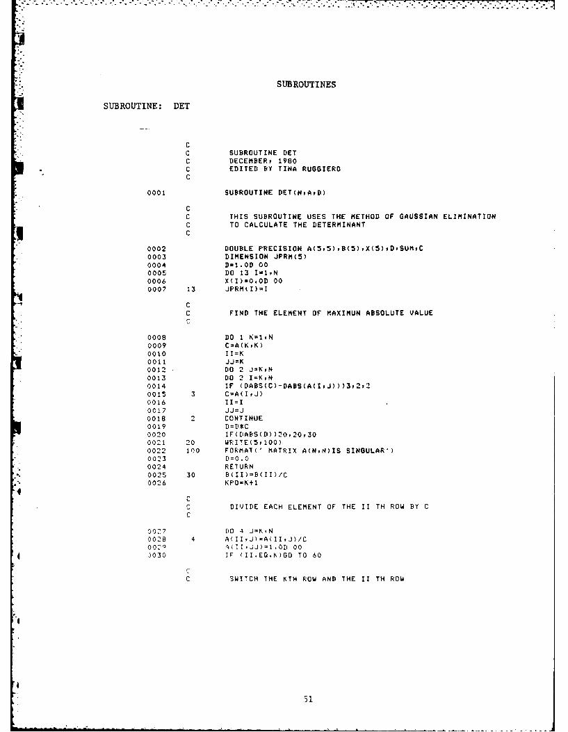
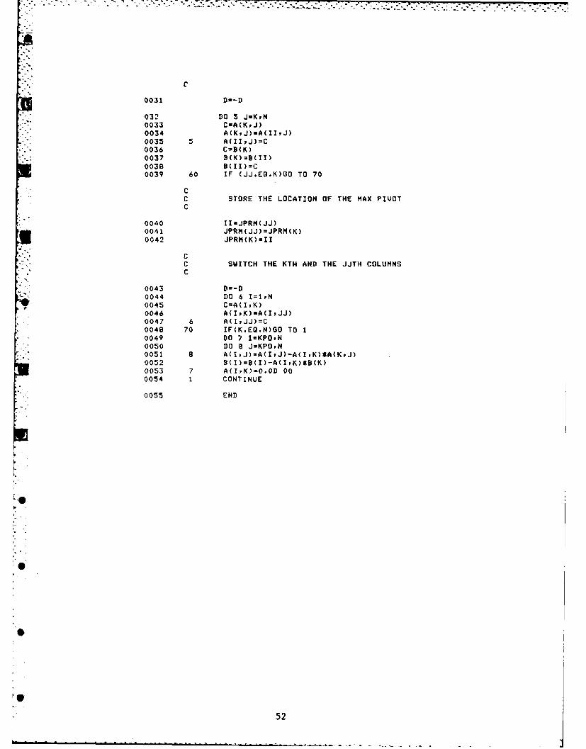
0001 SUBROUTINE DET(N,AD)
CC THIS SUBROUTINE USES THE METHOD OF GAUSSIAN ELIMINATIONC TO CALCULATE THE DETERMINANTC
0043 D=-D0044 DO 6 I=IPN0045 C=A(IK)0046 A(IPK)=A(IPJJ)0047 6 A(IPJJ)=C0048 70 IF(K.EQ.N)GO TO 10049 DO 7 I=KPOrN0050 DO 8 J-KPOvN0051 6 A(IPJ)=A(IYJ)-A(IPK)*A(KPJ)0052 B(ID=B(I)-A(IvK)*B(K)0053 7 A~IK)=0.0D 000054 1 CONTINUE
0055 END
52
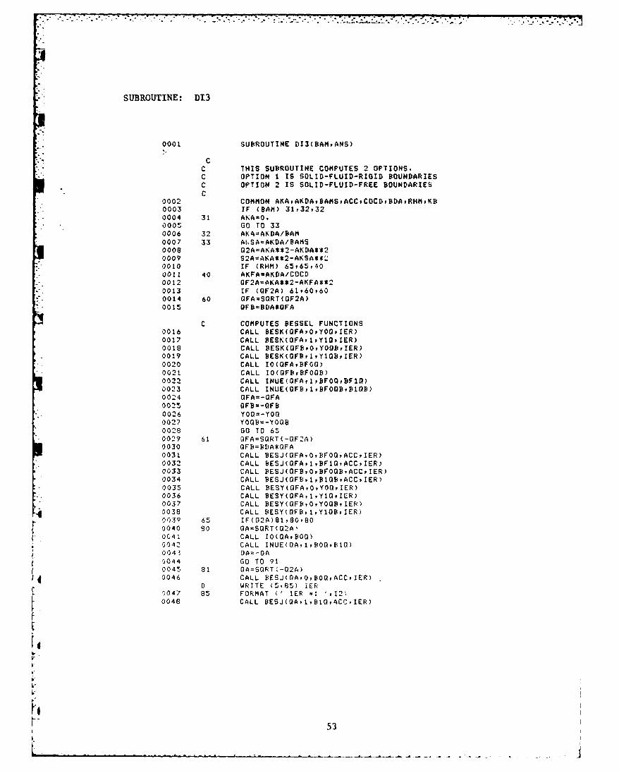
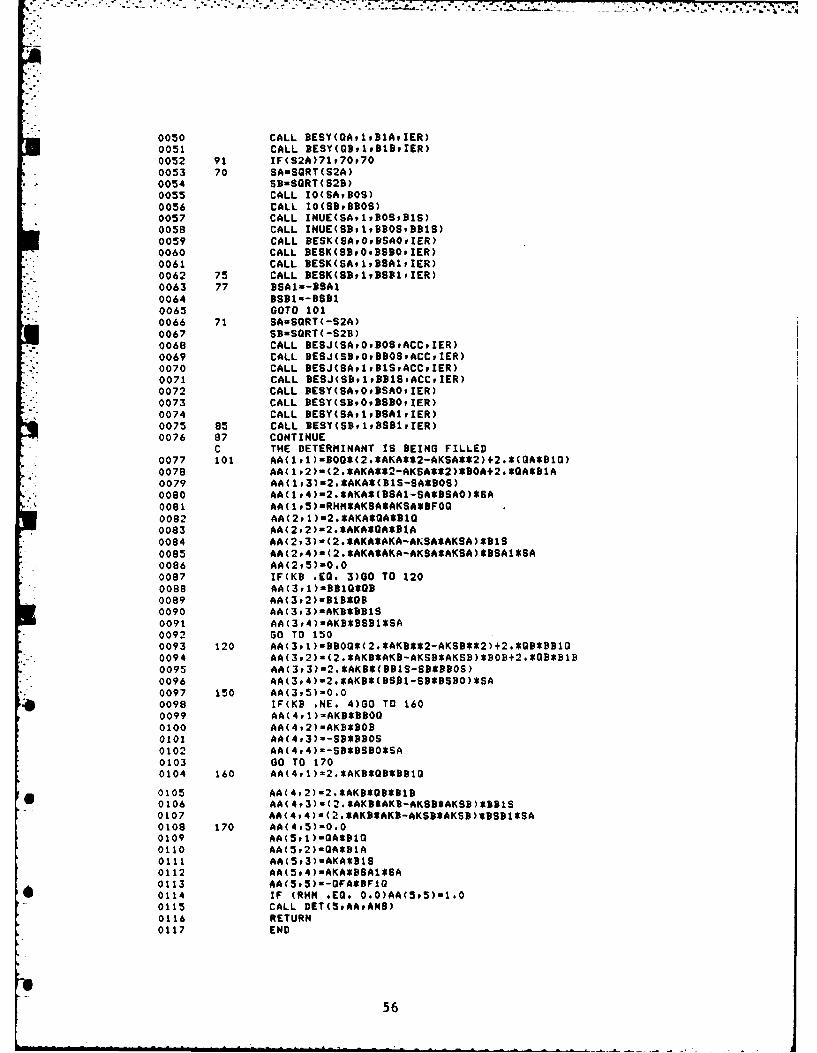
* SUBROUTINE: D13
0001 SUB~ROUTINE DI3(BA14,ANS)
* CC THIS SUBROUTINE COMPUTES 2 OPTIONS.C OPTION 1 IS SOLID-FLUID-RIGID BOUNDARIESC OPTION 2 IS SOLID-FLUID-FREE BOUNDARIESC
0002 COMMON AKAPAKDADAMSACCCOCDPBDARHMKD0003 IF (DAM) 31P32Y320004 31 ANA0O.0005 GO TO 330006 32 AKA=AKDA/BAM0007 33 AISA=AKDA/BAMS0008 02A=AKA**'-AKDA**20009 S2A=AKA**2-AKSA**20010 IF (RHM) 65P65P400011 40 AKFA-AKDA/COCD0012 OF2A-AKA**2-AKFA**20013 IF (OF2A) 61Y60P600014 60 QFA=S0RT(0F2A)0015 OFB=8DA*QFA
0047 85 FORMAT (' IER -: 'PI2)0048 CALL BESJ(QAt1,810,ACC.IER)
________
D WRITE (5P85) IER0049 91 IF M9A) 71P70,700050 70 SA=SGRT(S2A)0051 CALL IO(SAI40S)0052 CALL INUE(SAultDOS*91S)0053 G0 TO 1010054 71 SA-SORT(-52A)0055 CALL DE5J(SAP0PD0SPACCIER)
Il WRITE (Su85) IER0056 CALL BESJ(SAPIPD1S.ACCPIER)
D WRITE (5,83) IER0057 101 D11-B00*(2.*AKA**2-AKSA**2)+D1O*2.*OA0058 D12=2.*AKA*(D1S-SASDOS)0059 021=2.*AKA*OA*B1O0060 D22=B1S*C2.*AKA**2-AKSA**2)0061 IF (RHM) 21,21,220062 21 ANS-D11*D22-D12*D210063 G0 TO 110064 22 D13-AKSA**2*RNM*DFOG0065 D14=AKSA**2*RHM*YOG0066 D31=GA*81O0067 D32-AKAWBIS0068 D33-GFA*DF1G0069 034u-OFA*YIO0070 IF (lCD-1) 75P75P760071 76 D43=DFOOD0072 D44-Y00B0073 GO TO 780074 75 0430QF3*D1OB0075 D44=GFD*Y1OD0076 78 P12=011*D22-D12*D210077 P34=033*044-034*0430078 P23=021*032-D22*D310079 P14=013*D44-014*0430080 AN5=P2*P34-P23*P140081 11 RETURN0082 END
54
* SUBROUTINE: CALIB
0001 C SUBROUTINE CALIB(BAMANS)
C THIS SUBROUTINE CORRESPONDS TO THE OPTIONS 3prv AND 5.C OPTION 3 IS WHERE FLUID SOLID AND FREE BOUNDERIES IS ANALYZEDC OPTION 4 IS WHERE FLUID-SOLID-RIGID BOUNDERIESCCEMENTED)C OPTION 5 IS WHERE FLUID-SOLID-RIGID(NOT CEMENTED)C IS ANALYZED.
0002 DOUBLE PRECISION AA(5p5)0003 COMMON AKAPAKDABAMSACCCOCDBDARHMKBmAA0004 IF(BAM)31i32p320005 31 AKA0O0006 GO TO 330007 32 AKA=AKDA/BAM0009 33 AKSA=AKDA/BAMS0009 OZA=AKA**2-AKDA**20010 S2A=AKA**2-ANSA**20011 AKFAuAKDA/COCD0012 GF2A=AKA**2-AKFA**20013 AKB=AKA*BDA0014 AKSD=AKSA*BDA0015 G23=02A*BDA*BDA0016 S2B=S2A*BDA*BDA0017 IF(GF2A)61,60,600019 60 OFA=SGRT(GF2A)
C BESSEL FUNCTIONS ARE COMPUTED HERE40019 CALL I0(OFAPBF0Q)
C THE DETERMINANT IS BEING FILLED0077 101 AA( 1.1)mBOQ*(2.*AKA**2-AKSA**2)+2.*(QA*D10)0078 AA(IP2)-(2.*AKA**2-AKSA*$2)*30A42.3OASB1A0079 AA(lp3)s2.*AKA*(BIS-SA*DOS)0080 AA(1P4)u2.*AKA8(BSAI-SA*BSA0)*SA0081 AA(1#5)=RHM*AKSA*AKSASDPOQ0082 AA(2p1)=2.*AKA*QA*B1O0083 AA(292)s2.*AKASOA*D1A0084 AA(2,3)s(2.*AKA*AKA-AKSA*AKSA)*9190085 AA(2,4)=(2.*AKA*AKA-AKSA*AKSA)*DSAI*SA0096 AA(2t5)=0.00097 IF(KB .EQ, 3)90 TO 1200088 AA(3pl)=DD1O*GB
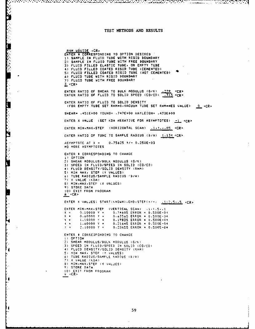
ENTER X VALUE (SET KDA NEGATIVE FOR ASYMPTOTES) -1 <CR >
ENTER MINtMAXSTEP (HORIZONTAL SCAN) .lvl.P.05 <CR>
ENTER RATIO OF TUBE TO SAMPLE RADIUS (B/A) 1.134 <CR>
ASYMPTOTE AT X = 0.75625 +/- 0.250E-03NO MORE ASYMPTOTES
ENTER t CORRESPONDING TO CHANGE1) OPTION2) SHEAR MODULUS/BULK MODULUS (G/K)3) SPEED IN FLUID/SPEED IN SOLID (CO/CD)4) FLUID DENSITY/SOLID DENSITY (RHM)5) MIN MAX, STEP (Y VALUES)6) TUBE RADIUS/SAMPLE RADIUS (B/A)7) X VALUE (KDA)8) MINMAXSTEP (X VALUES)9) STORE DATA10) EXIT FROM PROGRAM8 <CR>
ENTER X VALUES: START(NNOWN),ENDSTEF'(+/-) .2.5. .5 <CR>
ENTER MINMAX,STEF (VERTICAL SCAN) .1,1.5,.lX = 0.10000 Y = 0.74605 ERROR = 0.500E-01X . 0.60000 Y z 0.63565 ERROR = 0.500E-04
z 1 .10000 y z 0.19835 ERROR = 0.500E-041.60000 Y = 0.21645 ERROR = 0.500E-04
X 2.10000 Y = 0.23655 ERROR = 0.500E-04
ENTER t CORRE3PONDING TO CHANGE1) OPTION2) SHEAR MODULUS/BULK MODULUS (G/K)3) SPEED IN FLUID/SFEED IN SOLID (CO/C')4) FLUID DENSITY/SOLID DENSITY (RHM)5) NIN MAX, STEP (Y VALUES)6) TUBE RADIUS/SAMFLE RADIUS (B/A)7) X VALUE (KDA)9) MINMAX,STEF (X VALUES)9) STORE DATA
10) EXIT FROM FROGRAMS<CR>
4 59
SFILE NAME FOR XPY DATA:DATA <CR>
ENTER $ CORRESPONDING TO CHANGE1) OPTION2) SHEAR MODULUS/BULK MODULUS (G/K)3) SPEED IN FLUID/SPEED IN SOLID (CO/CD)4) FLUID DENSITY/SOLID DENSITY (RHM).5) MIN MAX, STEP (Y VALUES)6) TUBE RADIUS/SAMPLE RADIUS (B./A)7) X VALUE (KDA)8) MINPMAXPSTEF (X VALUES)9) STORE DATA10) EXIT FROM PROGRAM10 <CR>
1.) All underlined portions are user supplied.
2) <CR> indicates 'RETURN'
60
* -
*" .SCuPTIO Or PROGRAM Imm
The program IMPED computes values for the complex dimensionlesspropagation speed in the solid sample (assumed infinite in length) inside theimpedance tube. Input to the program are the complex values for the ratio ofshear modulus to bulk modulus G/K, and the speed in the fluid divided by thedilatational wave speed in the solid, c /cd. Thus, it may be considered asthe complex counterpart to program WGUIB-, Option 1. The root finding
technique is identical to that used in program RURE.*
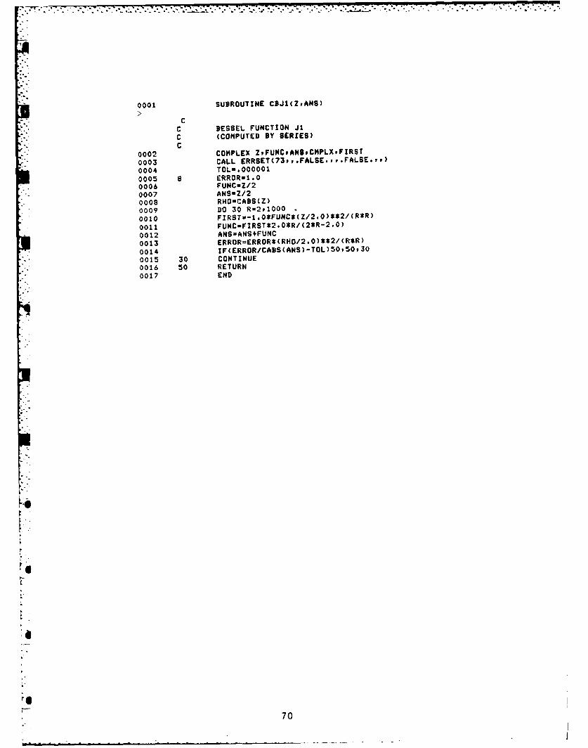
Subroutines for Bessel functions were written by direct series expansionsince the real part of the argument is small enough that a small number ofterms suffices. The names of the subroutines are CBJO, CBJ1, CBYO, and CBY1,where the last two letters of each name indicate kind and order of the Besselfunction.
The output produced by the program is in the form of real and imaginaryparts of the relative wave speed B - c/cd, each with its own error limit,corresponding to the input error limits set separately for the two terms. Theattenuation constant may be readily calculated by a - -k d /($ 2 + 22)
where m is the attenuation per unit of length and 81 and 02 are the real andimaginary parts of B which is equal to c/cd. If the propagation of the wavein water is assumed to be without loss (co real), the input value of AKIDAshould have the same ratio of imaginary to real part as COCD.
Importat Variables in DIMED
Input Variables
AKDA (k a), Dimensionless wave number of dilatational waves,l (a)/cd (real & complex)
AMI # of iterations
ANR # of divisions of imaginary part
BAM (c/cd) relative wave speed; enter real part of c/cd (ZNOT)
BDA (b/a) b - radius of tubea - radius of cylindrical sample
COCD (co/cd) - wave speed in fluid divided by dilatational wave
speed in solid (real and complex)
DELZ (used in computation of stepsize)
GOK (G/K) (real and complex) G - shear modulus, K - bulk modulus
* P.S. Dubbelday, "Complex Root-Finding Program with Application to theDispersion Relation of Waves Propagating in a Fluid Plate," NRL MemorandumReport 4559, November 1981.
61
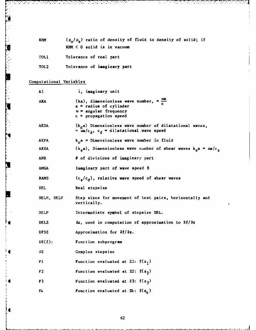
RHM (po/Ps) ratio of density of fluid to density of solid; if
RHM < 0 solid is in vacuum
* TOLl Tolerance of real part
TOL2 Tolerance of imaginary part
Computational Variables
AI i, imaginary unit
AKA (ka), dimensionless wave number, wa
a = radius of cylinder C
w - angular frequencyc - propagation speed
AKDA (kda) Dimensionless wave number of dilatational waves,= ca/cd, cd = dilatational wave speed
AKFA k0a - Dimensionless wave number in fluid
AKSA (ksa), Dimensionless wave number of shear waves ksa = ha/c s
ANR # of divisions of imaginary part
AMGA Imaginary part of wave speed 8
BAMS (cs/cd), relative wave speed of shear waves
DEL Real stepsize
DELH, DELV Step sizes for movement of test pairs, horizontally andvertically.
DELP Intermediate symbol of stepsize DEL.
* DELZ Az, used in computation of approximation to af/az
DFDZ Approximation for 3f/3z.
DS(Z): Function subprogram
OZ Complex stepsize
F1 Function evaluated at Zl: f(zI)
F2 Function evaluated at Z2: f(z2 )
F3 Function evaluated at Z3: f(z3 )
F4 Function evaluated at Z4: f(z4 )
I62
I
. FVl, FV2
FMI, FV2 Flags to indicate direction of motion of test pairs
FSTEP Factor to adjust step size DEL
lOP Return option number- 1 Program returns to entering COCD, GOK, AKDA- 2 Program returns to entering Real Seed, # ofiterations, DELZ, BDA= 3 Program returns to entering AWR, TOL (Real), TOL(Imag.), RHM- 4 Program exits
KAM - AMI
KR, KLKUP, KDO Counters in loops to check number of iterations
NR =ANR
NRV Counter in advancing the parameter RHO
Q2A (qa) 2 = (ka) 2 - (kda)2
QF2A (qoa)2 (ka)2 - (koa)2
QF2B (q0b)2 = (kb) 2 - (k0a)
2
REGA Real part of relative wave speed 0
RHM Nominal density of fluid loading the plate, divided bydensity of plate material.
RHO Stepwise varied value of relative density, varying fromzero to RHM
SIGN Expression, the algebraic sign of which determines locationof root relative to test pair.
TOL Limit for relative error in the root.
Z Variable for root used in calling subroutines
Zl, Z2 Vertical test pair
Z3, Z4 Horizontal test pair
ZNOT Value for the real root of the disporsion relation from areal root finder, serving as the .eed for starting theprogram.
ZVAR Intermediate value of root, serving as seed for the nextstep, in parameter RHO
63
* ZVAR Intermediate value of root, serving as seed for the next
step, in parameter RHO
"* Output Variables
. AMGA Imaginary part of root
ZEGA Real part of root
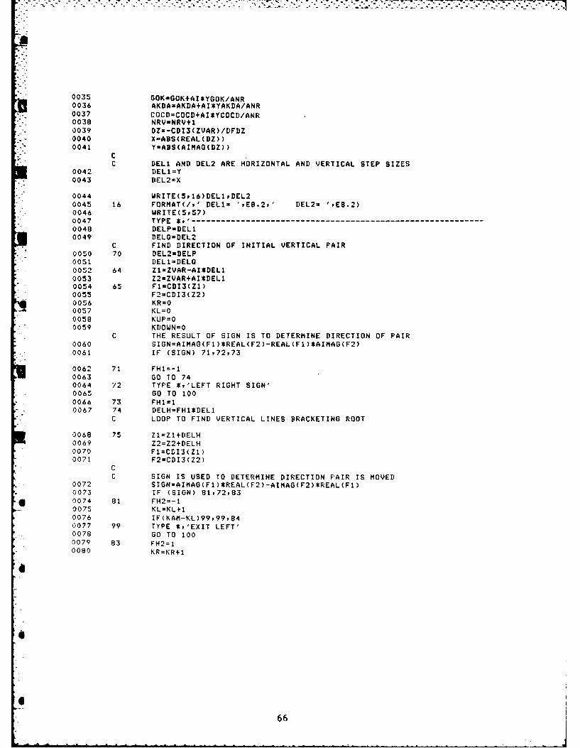
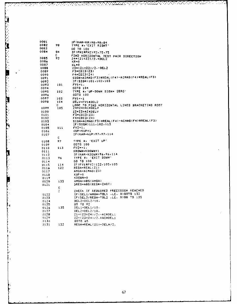
* Major Computation Block in IPED
Refer to major computation blocks in R0819
6
0.
m .64
C COMPLEX ROOTFINDING ROUTINEC WRITTEN BY TINA RUGGIEROC DECEMBER 17P1981CC THIS COMPLEX ROUTINE INTRODUCED BY DUIBELDAYC ALLOWS THE USER TO SOLVE FOR BOTH THE REAL AND IMAGINARYC PARTS OF A COMPLEX ROOT, GIVEN A REAL ROOT IN THEC VICINITY AS A SEED.CCC SUBROUTINES USED:C CDI3 (CONTAIN FUNCTION DESCRIBED BY DETERMINANT OF A SET OFC BOUNDARY CONDITIONS)C CEJO (BESSEL FUNCTION (JO))C CBJ1 (BESSEL FUNCTION (Ji))C CBY0 (BESSEL FUNCTION (YO))C CBYI (BESSEL FUNCTION CYl))C
Cc SIGN IS USED TO DETERMINE DIRECTION PAIR IS MOVED
0072 SIGN=AIMAG(F1)*REAL(F2)-AIMAG(F2)*REAL(F1)0073 IF (SIGN) 81,72,830074 81 FH2=-10075 KL=KL+I0076 IF(KAM-KL)99,99,840077 99 TYPE *,'EXIT LEFT'0078 GO TO 1000079 83 FH2=10080 KR=KR+1
6
6
666
0081 IF(KAM-KR)98,98,840082 98 TYPE E.'EXIT RIGHT'0083 60 TO 1000084 84 IF(FHI$FH2)92,75975
C FIND HORIZONTAL TEST PAIR DIRECTION0085 92 Z4=(ZI+Z2)/2.+DEL20086 KRUO0087 KL=O0088 Z3-(Z1+Z2)/2.-DEL20089 F3=CDI3(Z3)0090 F4=CDI3(Z4)0091 SIGN-AIMAG( F3)*REAL (F4) -AIMAG( F4 )*REAL(F3)
C CHECK IF FINAL G0K AND AKDA IS REACHED0138 IF(NR-NRV) 145' 145' 1460139 146 ZVAR=REGA+AMGA*AI0140 GOK=GOK+AI*YGOK/ANR0141 AKDAsAKDA+AIEYAKDA/ANP0142 COCD=COCrI+AIEYCOCD/ANR0143 NRV=NRV+i0144 GOTO 700145 145 CONTINUE0146 TYPE *90147 100 TYPE *y' ENTER OPTION t (lvp3v4)0148 READ(5,160)IOF0149 160 FORMAT(12)0150 G0 TO (5,25,45y550)vIOF0151 550 END
0001 FUNCTION CD13CBAM)0002 COMMON AKAvAKDAvCOCDp9DArRHMvGOK0003 COMPLEX AKAAKDADAMSPCOCDAKSA,02AS2AAKFAQF2AOFAGFUDBFOO,
0054 P23-D21*D32-D22*D310055 P14=D13*D44-D14*D430056 CDI3-P12*P344P23*P140057 11 RETURN0058 1000 TYPE WARGUMENT FOR BESSEL FUNCTIONSP TOO LARGE'0059 2000 END
69
* - -,~,*-~.-.----~~--7--- - I S . ~ -~7
0001 SUBROUTINE C9J1(ZrANS)
CC BESSEL FUNCTION JiC (COMPUTED BY SERIES)C
0002 COMPLEX ZFUNCoAN3,CMPLX.FIRST0003 CALL ERRSET(73,,.FALSE.,,.FALSE.vv)0004 TOL=.0000010005 a ERRORI1.00006 FUNCmZ/20007 ANSsZ/20008 RHOsCABS(Z)0009 DO 30 R-2,1000
APPUDIX BCorrection for Imperfect Reflector in Impedance Tube
The analysis of the role of the reflector in the impedance tube startsfrom the observation that there are traveling waves in both directions in thewater of the impedance tube, in the sample, and in the reflector, each withits own amplitude and phase. By equating stress and particle velocity at eachof the interfaces one may infer the reflection coefficient for the followingcases: rsa is the reflection coefficient without the sample in place, rst isthe reflection coefficient without the sample. One would like to relate thesemeasured quantities to the reflection coefficient r used in Eq. (2), whichimplies a perfect reflector. The length £ of the reflector is chosen suchthat krX is close to w/2. The subscript r refers to the reflector. Defineby krt I w/2 + S, 6 is a small complex number. One finds that
1 - i(tan ksd)(pc)o/(PC)1 + i(tan k d)(pc) /(Pc) s (B3)
where the parameter e is defined by e - (tan 6)(Pc)o/(Pc) r.
In the present data analysis, the reflection coefficient r in Eq. (2) isreplaced by rc, defined by
rc = exp(-21k d)r sa /r st (B4)
The correction factor applied to rsa according to this equation may beexpressed in terms of the small parameter £ by
exp(-21k d)/r st i + 21c . (B5)
The proper correction factor is r/rsa, which may be expressed to the sameorder by
73
r/rsa 1 + 2iFe , (B6)?.a
where the factor F is given by
F = 1/Icos2kd + sin2 kd[(pc) /( pc) ]2. (B7)
This factor F may be noticeably different from one, if the complex specificacoustic impedance of the sample material is not very close to that of thewater in the tube. Even though densities and propagation speeds of sample andwater might be close, as is the case for elastomers, a difference inattenuation still would make this factor unequal to one.
This proposed correction does not consider the effect of the terminationof the tube by the reflector and the consequent deviation from the idealizedsituation of an infinite waveguide.