15
EIC Meeting, Stony Brook University, January 10, 2010 Dmitry Kayran for MeRHIC group EIC Meeting January 10 - 12, 2010 MeRHIC: Injection System
| Date post: | 01-Jan-2016 |
| Category: |
Documents |
| Upload: | angela-kennedy |
| View: | 215 times |
| Download: | 1 times |

EIC Meeting, Stony Brook University, January 10, 2010
Dmitry Kayran for MeRHIC group
EIC Meeting
January 10 - 12, 2010
MeRHIC: Injection System

EIC Meeting, Stony Brook University, January 10, 2010
(April 09)
Linac 1
Linac 2
Main ERLs; 6 cryomodules x 6 cavities x 18 Mev/cav = 0.65 GeV per linac
0.75, 2.05, 3.35 GeV
4 GeV
0.1, 1.4, 2.7 GeV
Pre-accelerator 90 MeV ERL
Electrongun 0.1 GeV
IR2 region features: - asymmetric detector hall (appropriate for asymmetric detector for e-p collisions) - long wide (7.3m) tunnel on one side from the IR (enough space to place energy recovery linac(s))
Main components:
-100 MeV injector on the basis of polarized electron gun (50 mA) and pre-accelerator ERL.
-Two main ERLs (one of them in the RHIC tunnel) with maximum 0.65 GeV energy gain per linac.
-Recirculation passes are going outside of the existing tunnel: warm magnets, acceptable synchrotron radiation power.
10 MeV Injector
90 MeV Linac 1 cryomodule 5 cavities+3rd harmonics
100 MeV100 MeV
11 m11 m 10 MeV x 50 mA
0.5 MW Beam Dump
Merger to MeRHIC
Merger from eRHIC Merger to eRHIC100MeV pre-accelerator
MeRHIC: General layout

EIC Meeting, Stony Brook University, January 10, 2010
100 MeV Pre Accelerator ERL
3
Injector ParametersPolarized Gun (200kV)Cathode GaAs,Laser 780nm Emax= 10 MeV Iavr =50 mA, Q per bunch =5nC
Pre-accelerator ERL: One passEnergy gain 90 MeVEinj & Eextr=10 MeVEmax =100 MeV
eBeam parameters : E=100 MeVIavr=50 mAIpeak=500 ARep.rate = 9.8 MHzEmittance =70 mm-mradBanchlength = 2-3 mm dE/E = 1E-3
Gatling Gun (Ek=200keV)
10 MeV Injector 90 MeV Linac
1.4, 2.7, 4 GeV
11 m 11 m10 MeV x 50 mA
0.5 MW Beam Dump
from MeRHICarcs
to MeRHIC vertical combiner
10 MeV Booster Linac
30 m
EIC Meeting, Stony Brook University, January 10, 2010
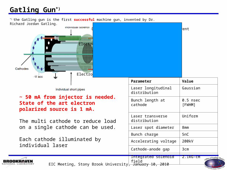
Gatling Gun*)
Parameter Value
Laser longitudinal distribution
Gaussian
Bunch length at cathode 0.5 nsec [FWHM]
Laser transverse distribution
Uniform
Laser spot diameter 8mm
Bunch charge 5nC
Accelerating voltage 200kV
Cathode-anode gap 3cm
Integrated solenoid field 2.1kG-cm
Dogleg funneling system is spin transparent
Electrostatic kicker
Rotating field kicker
~ 50 mA from injector is needed. State of the art electron polarized source is 1 mA.
The multi cathode to reduce load on a single cathode can be used.
Each cathode illuminated by individual laser
*) the Gatling gun is the first successful machine gun, invented by Dr. Richard Jordan Gatling.
Electrostatic kicker

EIC Meeting, Stony Brook University, January 10, 2010
Laser
No Commercial Laser to meet the need!
LDRD for laser development 2W/mA (780 nm, 0.1% QE)• Three possible approaches:
– Fiber oscillator Fiber amplifier 2ћω to 780 nm– Ti:S Oscillator Ti:S amplifier 780 nm– Diode oscillator Power amplifier 780 nm
• All three approaches will be evaluated• Best selected, built & test to drive up to 2 mA
Expected Results• Laser to drive one cathode of the multi cathode gun• Laser system scalable to deliver full EIC electron beam
2 LDRD’s for the new injector and laser have been approved

EIC Meeting, Stony Brook University, January 10, 2010
Beam pipe radius: 5cm
DC Gun voltage 200 kV, GaAs cathode, with funneling system (L=1.5 m).
Spin rotator ( Wien filter: B=36Gs, E=751 kV/m, 1m, spin rotation 90 degrees) .
Bunching cavity is a low frequency (112MHz) cavity with outer radius of about 105cm
3rd harmonic frequency (336MHz) cavity with outer radius of about 35cm
Booster linac (6x112MHz cavity ) boosts the beam energy to 10MeV (L=4.5 m).
So
len
oid
Gun
200 KeV
Spin rotator
So
len
oid
So
len
oid
Bunching Cavity
3rd harmonic cavity
So
len
oid
11 m
10MeV Injector layout
10 MeV booster linacE B

EIC Meeting, Stony Brook University, January 10, 2010
1.4, 2.7 GeV and 4 GeV beam lines are separated vertically.Each pass can be tuned separately.
30 m
Low/High Energy Switch yards
11 m10 MeV 10 MeV
10 MeV, 100MeV 100 MeV, 10MeV
100MeV100MeV
2 Dog-Legs (at 10MeV):
2 x30°dipoles,B=560 Gauss L=30 cm
6 quadrupoles
2 Dog-Legs(at 100MeV):
2 x30° dipoles, B=5.6 kGauss, L= 30 cm
6 quadrupoles
Beam Dump
Injector

EIC Meeting, Stony Brook University, January 10, 2010
MeRHIC Pre-accelerator: 90 MeV Linac
Pre-accelerator linac:Standard MeRHIC linac cryomodule (L~10m) with 5x703 MHz 5-cell cavities and one 3rd harmonic 2.11 GHz inside.Two transition sections (L=0.5 m each) attached from both ends Energy gain 90 MeV
10 MeV 10 MeV
100 MeV100 MeVStandard main MeRHIC linac cryomodule
Transition section Transition section
703.75 MHz
2.11 GHz

EIC Meeting, Stony Brook University, January 10, 2010
0
50
100
150
200
250
300 350 400 450 500 550
Z, cm
Po
we
r d
en
sit
y, W
/cm
2
0
10
20
30
40
50
Ap
ert
ure
, cm
P, W/cm2
Collector contour
R&D ERL: Beam dump
Simulation Setup:Bending dipole:
30 degree, R=60 cm
Spreader:
focusing solenoid:
L= 10 cm, B= 2.7 kGauss
Particles trajectories in collector
Power density distribution
Strong solenoid
Modified 1MW CPI Klystron beam collector
to accept 1MW= 2 MeV x 500mA beam
(MeRHIC parameters: 10 MeV x 50mA=0.5 MW)

EIC Meeting, Stony Brook University, January 10, 2010
2-3 MeV
2-3 MeV
20 MeV
20 MeV
20 MeV
2-3 MeV
SC RF GunSC 5 Cell cavity
Beam dump
BPM
DCCT
1MW Klystron
SRF Linac50 kW Transmitter ready to operate
Arc assembly
Quadrupole
Dipole
Tested in
BLD912
ready for
gun
First cool-down, March, 2009 T=2K
Measured, ready to be
installed
BNL R&D ERL: Status
SRF Gun

EIC Meeting, Stony Brook University, January 10, 2010
Major issues to be addressed at BNL R&D ERL
• eRHIC/MeRHIC:– very high average current
SRF injector BBU, e-dump
• Proof of principal of coherent e-cooling / conventional pre-cooling – High charge per bunch– Low energy spread and emittances (3rd harmonic is needed)– Conservation of beam parameter in merger (Z-bend test will give an answer)– Ion bunch much longer then electron one (703.75 MHz train of e-bunches helps,
will split laser beam to 2/4/8)
For all projects Stability criteria for CW beam currentHalo/losses control (G5 test will give us more information, first study then
collimators at low energy in injection line will be installed )

EIC Meeting, Stony Brook University, January 10, 2010
ERLs beam parameters
R&D ERL design BNL ERL projects requirements
High Current High charge PoP CeC Test *) Pre-cooling @ 40GeV
MeRHIC eRHIC
10/20
Charge per bunch, nC 0.7 5 5 5 14 (9x1.56) 5 18/3.5
Energy maximum/injection, MeV 20/2.5 20/3.0 21/3 21/3 21/3 4000/10 10000/10
20000/10
R.m.s. Normalized emittances ex/ey, mm*mrad
1.4/1.4 4.8/5.3 5 5 3 7-73 77
R.m.s. Energy spread, E/E 3.5x10⁻³ 1x10⁻² 1.5x 10⁻³ 1.5x 10⁻³ 8 10-4 2x10⁻³ 1x10⁻³
R.m.s. Bunch length, ps 18 31 30 30 30 6.7 30
Bunch rep-rate, MHz 700 9.383 0.078 9.383 9.383 9.383 14.1
Gun/dumped avrg. current, mA 500 50 0.4 50 130 50 50
Linac average current, mA 1000 100 0.4 0.4/50 130 300 500
Injected/ejected beam power, MW 1.0 0.150 0.0012 0.15 0.390 0.5 0.5
Numbers of passes 1 1 1 1 1 3 5

EIC Meeting, Stony Brook University, January 10, 2010
Summary
100 MeV Pre Accelerator main elements: • 10 MeV Injector:
– the most challenging Polarized Gun/Cathode/Laser (approved 2 LDRD starts in 2009 )– Spin rotator & power supply– Booster, Bunching, 3rd harmonics
• 90 MeV linac will use:– One MeRHIC standard 10m cryo- module (going on research)– With 5 standard MeRHIC cavities + 3rd hormonic
• Doglegs and matching sections– Magnets & Power supplies (dipoles, solenoids, quadrupoles, correctors)
• Beam dump is modified CPI Klystron electron beam collector similar what used for BNL R&D ERL
Based on simulations: 10 MeV Injector will provide e-beam with required parameters both longitudinal and transverse
• Beam dynamics of high energy part (100 MeV) pre accelerators does not look challenging but needs to be done
The R&D ERL (2011) will address key questions relevant to MeRHIC/eRHIC ERLs.• High average current ERL operation• R&D ERL can be used to proof-of-principal coherent electron cooling

EIC Meeting, Stony Brook University, January 10, 2010
Thank you!

EIC Meeting, Stony Brook University, January 10, 2010
Commisionnig plan: ERL fully operational in 2011
We start commissioning of the R&D ERL in 20095cell SRF cavity cold emission test (first cool-down March, 14 2009)•First, we develop the straight pass (gun -- 5 cell cavity -- beam stop) test for the SRF Gun performance studies. (end of 2010)
#Metal cathode (low charge per bunch)
#Multi-Alkaline Cathode (up to 5nC per bunch)•Next, a novel concept of emittance preservation in a beam merger at the lower energy will be tested ( 2010)
•After recirculation loop completed, demonstrate energy recovery of high charge and high current beam.The prototype will serve as a test bed for studying issues relevant for very high current ERLs (2011)
•Proof of principle coherent electron cooling ions in RHIC at ~ 40 GeV/n is feasible with existing R&D ERL parameters (ERL available around 2012)


