EUROPEAN ORGANISATION FOR THE SAFETY OF AIR NAVIGATION EUROCONTROL EXPERIMENTAL CENTRE EIGHT-STATES FREE ROUTE AIRSPACE PROJECT 4 th SMALL SCALE REAL TIME SIMULATION EEC Note No. 17/2000 Project AOM-Z-FR Issued: December 2000 The information contained in this document is the property of the EUROCONTROL Agency and no part should be reproduced in any form without the Agency’s permission. The views expressed herein do not necessarily reflect the official views or policy of the Agency. EUROCONTROL
Transcript
EUROPEAN ORGANISATIONFOR THE SAFETY OF AIR NAVIGATION
EUROCONTROL EXPERIMENTAL CENTRE
EIGHT-STATES FREE ROUTE AIRSPACE PROJECT4th SMALL SCALE REAL TIME SIMULATION
EEC Note No. 17/2000
Project AOM-Z-FR
Issued: December 2000
The information contained in this document is the property of the EUROCONTROL Agency and no part shouldbe reproduced in any form without the Agency’s permission.
The views expressed herein do not necessarily reflect the official views or policy of the Agency.
This report describes the fourth small-scale real-time simulation study of the Free Routes Airspace Conceptwithin the context of the Eight-States Free Routes Airspace Project. Belgian and Dutch airspace wassimulated. The simulation was designed to support the validation of the Free Routes Airspace Concept, andwas the fourth of six planned real-time simulation studies. The study focused on the military operations inthe Free Routes environment, with special emphasis on the possibility for the military airspace users tocontinue the various types of operations in the Free Routes environment with adequate freedom and toassess any increase in workload or complexity for military ATC. The simulation also addressed the possibleneed for added system functionality in military ACC systems in order to support civil Free Routes Operation.Human Performance, Human Error and Safety issues were addressed in parallel studies conducted withinthe framework of the Free Routes Airspace Project, using the simulation as a vehicle to provide data
This document has been collated by mechanical means. Should there be missing pages, please report to:
Centre du Bois des Bordes B.P. 1591222 – BRETIGNY-SUR-ORGE CEDEX
France
FRAP SRT-4 EUROCONTROL
Project AOM-ZFR v
SUMMARY
This is the report of the 4th Eight-States Free Routes Airspace Project Real-timeSimulation. The simulation is one in a series of six real-time simulations, that togetherwith a number of other activities provides the basis for the validation of the FreeRoutes Airspace Concept.
The simulation was conducted at the EUROCONTROL Experimental Centre, andlasted for two weeks. Eleven air traffic controllers from BELGA RADAR, DUTCHMIL,MAASTRICHT UAC, TAMPERE ACC and MALMO ACC participated in the simulationwhere airspace covering Belgium and The Netherlands was simulated. The emphasisin this simulation was on military operations.
Functionality and Human Machine Interface expected to be in operation in the militaryACCs within the simulated area over the next five years formed the basis for theplatform used. This included OLDI/SYSCO, System Supported Civil-military Co-ordination and Short Term Conflict Alert. The HMI was a stripless, object based, colourcoded concept.
Flight plans assured that flights circumnavigated segregated airspace, in order toreduce the tactical workload when aircraft had to be vectored around segregatedairspace.
Most common types of military operations, transit flights, transit to/from TemporaryReserved Airspace (TRA), large formation flights, supersonic flights etc. wassimulated. Operations within TRAs were not simulated.
The simulation showed that the impact from Free Routes on Operational Air Traffic(OAT) operations is rather limited. The main effect seems to be a slight increase inworkload on the OAT controller. Procedures tested in Dutch airspace, known asMowing Windows Procedures, eliminated this increase in workload.
A similar set of procedures may, with future traffic growth, be necessary in Belgianairspace, but that is an effect of the introduction of RVSM more than Free Routes.
For Belgian airspace, procedures were proposed to reduce the time where TRAs areclosed for civil operations, in order to increase the flexibility of airspace usage.
The use of System Supported Civil-military Co-ordination and full exchange of flightplan between civil and military ATC data was seen as help to reduce workload.
The results in this report, although agreed between the participating military and civilcontrollers, shall be seen as simulation results only, and do not necessarily reflect theviewpoints of Belgian and Dutch military authorities.
EUROCONTROLFRAP SRT-4
Project AOM-ZFRvi
FRAP SRT-4 EUROCONTROL
Project AOM-ZFR vii
TABLE OF CONTENTS
Abbreviations .................................................................................................................... IxReferences, list of figures, list of tables ............................................................................. X
Abbreviation De-CodeAPW Area Proximity WarningATFM Air Traffic Flow Management
AR Air RoutesARN ATS Routes and associated Navigation meansATC Air Traffic ControlATM Air Traffic ManagementATS Air Traffic ServicesBAF Belgian Air ForceCFL Cleared Flight LevelCOP Coordination PointCWP Controller Working PositionEEC EUROCONTROL Experimental CentreEXC Executive ControllerFDP Flight Data ProcessingFIR Flight Information RegionFR Free Routes
FRA Free Routes AirspaceFRAC Free Routes Airspace ConceptFRAP 8-States Free Routes Airspace ProjectGAT General Air TrafficHMI Human Machine InterfaceISA Instantaneous Self Assessment
MTCD Medium Term Conflict DetectionOAT Operational Air TrafficOLDI On-Line Data InterchangeODS Operator Display SystemPLC Planner Controller
R&D Areas Restricted and Danger AreasRFL Requested Flight Level
RNLAF Royal Netherlands Air ForceRVSM Reduced Vertical Separation MinimaSSR Secondary Surveillance Radar
STCA Short Term Conflict AlertTRA Temporary Reserved AirspaceUIR Upper Information RegionXFL Exit Flight Level
EUROCONTROLFRAP SRT-4
Project AOM-ZFRx
REFERENCES
1. Eight-States Free Routes Airspace Project Management Plan ver. 1.02. Eight-States Free Routes Airspace Project EEC Activity Plan Plan ver. 1.03. Eight-States Free Routes Airspace Project SRT-4 Facility Specification Part 1
Figure Name Page1. Example of question ............................................................................. 32. Example of ISA Recording.................................................................... 43. Question, Training ................................................................................ 144. Question, Training ................................................................................ 145. Question, Traffic samles....................................................................... 156. Question, Feed sectors......................................................................... 157. Question, Level of Service.................................................................... 168. Question, Workload.............................................................................. 169. Question, Workload.............................................................................. 17
10. Question, Complexity............................................................................ 1711. Question, Civil-military Co-ordination.................................................... 1812. Question, Impact of TRAs..................................................................... 2013. Question, Flightplanning ....................................................................... 2014.. Recording, Average use of telephone................................................... 2415. Recording, Average use of radio .......................................................... 2416 ISA, Perceived workload, Basic System Scenario ................................ 2517. ISA, Perceived workload, Advanced System Scenario ......................... 2518 Question, MTCD................................................................................... 26
LIST OF TABLES
Table Name Page1. Sample description..................................................................................................... 42. Controller Working Position Configuration, Organisation 1 ...................... 53. Controller Working Position Configuration, Organisation 2 ...................... 64. R & D Areas............................................................................................. 65. Hourly throughput & Instantaneous Peaks during simulated exercises.... 76. Program of exercises............................................................................... 97. Priority Rules OAT/GAT, Belgian Airspace .............................................. 198. Priority Rules for TRA Penetrations ......................................................... 23
FRAP SRT-4 EUROCONTROL
Project AOM-ZFR 1
1. INTRODUCTION
The fourth Small Scale Real-time Simulation of the Eight-States Free Routes AirspaceConcept (FRAC) took place at the EUROCONTROL Experimental Centre between 4th
and 15th September 2000. The simulation was designed to meet the requirements ofFRAP to validate the Free Routes Concept (FRAC).
The simulation was one of six planned real-time simulations that, together with anumber of other activities, shall validate FRAC within the airspace of the eightparticipating states (Belgium, Denmark, Finland, Germany, Luxembourg, TheNetherlands, Norway, and Sweden).
This simulation is seen as a study simulation, where the concept is further developedas well as validated. The simulation was based on the upper airspace of AmsterdamFIR and Brussels UIR. The airspace structure was constructed to suit the requirementsof the simulation, mainly following military sector boundaries. Civil traffic was based oncollected traffic data from June 1999, augmented to the agreed sector load. Militarytraffic was based on data received from Belgian Air Force and Royal Netherlands AirForce.
The simulation focussed on military operations in Free Routes Airspace. Various typesof military operations, Formation flights, supersonic flights, transit flights to and fromTemporary Reserved Airspace (TRA), airborne early warning flights and airbornerefuelling was simulated, in order to assess the impact of FRA on these operations, todevelop procedures and to identify the need for added functionality in military AreaControl Centres (ACCs).
Two different system scenarios were used, a Basic System depicting today’s situationin many military ACCs and an Advanced System, depicting a more advanced situationwith full transfer of flight plan data and controller intentions together with systemsupported civil-military co-ordination.
The simulation was based on RVSM, OAT considered as non-RVSM capable.
The FRAP Human Performance Study was also part of the simulation, and performeda number of measurements related to human performances. The results of this studyare published in a separate report.
During the simulation the participating Air Traffic Controllers (ATCO’s) took part inthree half-day hazard analysis sessions to support the FRAP Safety Study.
The results in this report, although agreed between the participating military and civilcontrollers, shall be seen as simulation results only, and do not necessarily reflect theviewpoints of Belgian and Dutch military authorities.
EUROCONTROLFRAP SRT-4
Project AOM-ZFR2
2. OBJECTIVES AND MEASURES2.1 OBJECTIVES
The general objective of the simulation was to assess the impact on military operationsin Free Routes Airspace in an RVSM scenario.
More specifically the objectives were to:
1. Assess the effect of FRA on different types of OAT operations under various setsof procedures using different levels of system support
2. Develop and assess different sets of procedures for civil-military co-operation,including priority rules in FRA with respect to workload, efficiency, safety, takinginto consideration the effects of RVSM
3. Analyse the effect on TRA operation in FRA, including tactical activation anddeactivation of TRAs and the need for distribution of airspace status data.
4. Evaluate the possibilities for GAT traffic to transit TRAs including workload
5. Identify additional requirements for system support for military operations in FreeRoutes Airspace
2.2 MEASURES
In order to achieve the objective, the following measures were taken:
Subjective data
• Questionnaires, The controllers were asked to fill in questionnaires before andafter the simulation.
• Instantaneous Self Assessment (ISA) (See below)• Debriefings. Controller opinions were collected during the daily debriefings
Objective data
The following data-sets were recorded:• The number of pilot inputs/controller tactical instructions (level, heading,
direct)• Radio usage (number of calls per aircraft, average length of calls)• Average flying time per sector• The percentage of the flights cleared to cruise in the level requested in the
flight plan
2.2.1 Questionnaires
The participating controllers were asked to decide how much they agreed with anumber of statements related to ATC and FRAC, as described in the example below
FRAP SRT-4 EUROCONTROL
Project AOM-ZFR 3
Figure 1: Example of question
In the above example five civil and five military controllers agrees with the idea thattowers should be build higher, one military controller strongly agrees.
The opinion of six military and five civil controllers working on the simulated sectors isincluded in this report. The answers are indicated as the number of controllersselecting each possibility.
Comments given by the controllers in the questionnaires are listed below the subjectquestion.
2.2.2 ISA
ISA stands for Instantaneous Self-Assessment. It is a technique originally developedby DRA Portsmouth Maritime Command and Control and used here at the EEC forseveral years.
Each control position is equipped with a small box containing 5 buttons labelled:
• Very High• High• Fair• Low• Very Low
At five-minute intervals the controller is prompted by a flashing red light to press one ofthe five buttons corresponding to his perceived workload during the previous fiveminutes. The light flashes for 30 seconds during which time the controller mustrespond. At each interval a record is written of the button selected and the delay inresponding so that by the end of the exercise we have a history of the variation of eachcontroller’s perceived workload.
T h e re w a s e n o u g h tra in in g o n th e H M I, its ru le s a n d m e c h a n is m s
0
2
4
6
8
1 0
1 2
Strong
ly dis
agree
Disagre
e
Slightl
y Disa
gree
Slightl
y agre
eAgre
e
Strong
ly ag
ree
No.
of r
eplie
s
C iv il co n tro lle rsM ilita ry co n tro lle rs
EUROCONTROLFRAP SRT-4
Project AOM-ZFR4
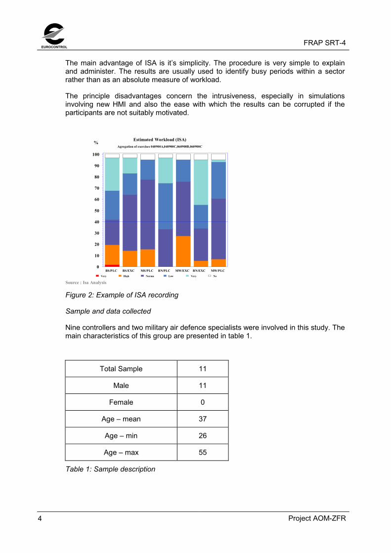
The main advantage of ISA is it’s simplicity. The procedure is very simple to explainand administer. The results are usually used to identify busy periods within a sectorrather than as an absolute measure of workload.
The principle disadvantages concern the intrusiveness, especially in simulationsinvolving new HMI and also the ease with which the results can be corrupted if theparticipants are not suitably motivated.
Estimated Workload (ISA)Agregation of exercises 040900A,040900C,060900B,060900C
Source : Isa AnalysisVery High Norma Low Very No
%
0
10
20
30
40
50
60
70
80
90
100
BS/PLC BS/EXC MS/PLC BN/PLC MW/EXC BN/EXC MW/PLC
Figure 2: Example of ISA recording
Sample and data collected
Nine controllers and two military air defence specialists were involved in this study. Themain characteristics of this group are presented in table 1.
Total Sample 11
Male 11
Female 0
Age – mean 37
Age – min 26
Age – max 55
Table 1: Sample description
FRAP SRT-4 EUROCONTROL
Project AOM-ZFR 5
3. SIMULATION CONDUCT3.1 AIRSPACE
3.1.1 The simulated area
The simulation airspace included parts of Amsterdam FIR and Brussels UIR.
In order to create a realistic traffic picture, parts of the surrounding airspace wasincluded in the simulation as feed sectors.
3.1.2 Sector Design Principles
The military sector structure was used as the basis for simulation sector design. ForBelga Radar, the present sectors were combined into two sectors covering Belgianairspace. Dutch airspace was covered by one military sector. Civil sectors wereequivalent to the military sectors.
This gave unrealistic big sizes of the civil sectors. This was necessary due to technicallimitations, i.a. the number of Controller Working Positions (CWPs) available. For thatreason the workload on the civil sectors was unrealistically high, it was howeverconsidered more important to have a correct traffic density to enable the militaryparticipants to judge the impact on their operations. A traffic density corresponding tothe predictions for 2003 was sought.
3.1.3 Operations Room Configuration
The operations room was configured with 10 CWPs. 7 of these CWPs were used formeasures.
Two different airspace organisations were simulated
• Organisation 1, covering Brussels UIR
• Organisation 2, Covering Amsterdam FIR and the northern part of Brussels FIR
Measured sectors were as shown in Tables 2 and 3 bellow:
SectorName
SectorCode
CWPsEXC
CWPsPLC
Belga North (MIL) BN 1 1
Belga South (MIL) BS 1 1
Maastricht West MW 1 1
Maastricht South MS 1 0
Table 2: Controller Working Position Configuration, Organisation 1
EUROCONTROLFRAP SRT-4
Project AOM-ZFR6
SectorName
SectorCode
CWPsEXC
CWPsPLC
Belga North (MIL) BN 1 1
Belga South (MIL) BS 1 1
Maastricht West MW 1 1
Maastricht South MS 1 0
Table 3: Controller Working Position Configuration, Organisation 2
3.1.4 Route Structure
Military TACAN routes were simulated as they are today. No civil route structure wasused during the simulation.
3.1.5 Restricted and Danger Areas and Temporary Segregated Airspace
The following Restricted and Danger Areas were included in the simulation:
Reference LevelEB - CBA 1A FL115 – UNLEB - CBA 1B FL225 – UNLEB - CBA 1C FL115 – UNLEB - TRA WEST BRAVO FL195 – UNLEB - TRA WEST DELTA FL195 – UNLEB - TRA NORTH BRAVO FL195 – UNLEB - TRA SOUTH BRAVO FL195 – UNLEH - R 8 (DEN HELDER) MSL - 32800ftEH - D41 MSL - 30000ftEH - D42 MSL - 30000ftEH - TRA01 FL055 - FL500EH - TRA02 FL055 - FL500EH - TRA03 FL055 - FL500EH - TRA04 FL055 - FL500EH - TRA05 FL055 - FL500EH - TRA06 FL055 - FL500EH - TRA07 FL055 - FL500EH - TRA08 FL055 - FL500EH - TRA09 FL055 - FL300EH - TSA A FL195 - FL660EH - TSA D FL195 - FL660EB - CBA 16B FL065 – UNL
Table 4: Simulated R&D Areas
All areas were designed in accordance with the national AIPs or in accordance withknown plans for future airspace design. Areas were activated and deactivated during
FRAP SRT-4 EUROCONTROL
Project AOM-ZFR 7
simulation exercises in accordance with a schedule agreed with the participating units.
3.2 TRAFFIC
3.2.1 Creation
Specialists from BAF and RNLAF created military traffic samples including all thedifferent types of flights required for the simulation. These samples were thenprocessed and converted into five traffic samples.
Civil traffic samples were created from IFPS traffic recordings of 18th June 1999. Afterthe data collection, the traffic samples were analysed and considered to berepresentative. No unusual ATFM or weather constraints were identified for thatparticular day. The levels of aircraft were then transformed into RVSM levels, using theguidelines developed by the RVSM project finally the civil traffic was combined with themilitary traffic samples.
Five base samples were then created with traffic levels corresponding to year 2003forecasts. In addition a set of traffic samples with reduced traffic level was created, toallow the civil controllers to get used to the relatively high workload. Traffic wasreduced with approximately 20%. The number of flights in each traffic sample can beseen in Table 6 below.
The five base traffic samples corresponds to different periods along the day, to get arealistic picture of the different traffic situations that normally occurs.
Each sample covered a time period of 1 hour 15 minutes, 60 minutes of which wasmeasured for analysis purposes.
Civil traffic was routed directly from the entry point to FRA airspace to the exit pointfrom FRA airspace, however segregated airspace was circumnavigated by addingadditional points to the route in order to simulate a scenario where operators wereobliged to submit flight plans that do not penetrate segregated airspace.
3.2.2 Traffic Sample Analysis
The analysis of the traffic samples below is based on recording from the simulationand shows the actual simulated load that each sample represented for the simulatedmeasured sectors.
EUROCONTROLFRAP SRT-4
Project AOM-ZFR8
Trafficsample
Time slot Sector Reduced Traffic 2003 traffic
Flow/hour
Peak Flow/hour
Peak
Maastricht South 48 13 Not simulatedMaastricht West 46 15 Not simulated
T1 08:50-09:50
Maastricht Delta 52 17 Not simulatedMaastricht South Not simulated 70 17Maastricht West Not simulated Not simulated
T2 10:50-11:50
Maastricht Delta Not simulated 80 31Maastricht South 44 11 53 14Maastricht West 46 18 64 19
T3 13:30-14:30
Maastricht Delta 44 17 Not simulatedMaastricht South 54 16 Not simulatedMaastricht West 46 15 62 16
T4 15:30-16:30
Maastricht Delta 43 14 69 24Maastricht South 48 11 80 29Maastricht West 48 13 80 23
T5 17:30-18:30
Maastricht Delta 52 18 Not simulated
Table 5: Hourly Throughput & Instantaneous Peaks during simulated exercises
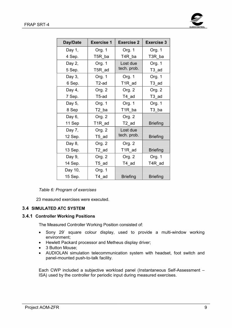
3.3 PROGRAM OF EXERCISES
In the Program of Exercises below, exercises are marked Org. 1 or Org. 2 inaccordance with the description in Para. 3.1.3. Exercises run in the Basic SystemScenario are labelled _ba, exercises run in the advanced system scenario are labelled_ad. A description of the system scenarios is included in Para. 3.4.4.
The Measured Controller Working Position consisted of:
• Sony 29’ square colour display, used to provide a multi-window workingenvironment;
• Hewlett Packard processor and Metheus display driver;• 3 Button Mouse;• AUDIOLAN simulation telecommunication system with headset, foot switch and
panel-mounted push-to-talk facility.
Each CWP included a subjective workload panel (Instantaneous Self-Assessment –ISA) used by the controller for periodic input during measured exercises.
EUROCONTROLFRAP SRT-4
Project AOM-ZFR10
3.4.2 System Functionality
3.4.2.1 Surveillance
The entire simulated area was covered by radar. In general the vertical limits of radarcoverage were from ground to unlimited.
3.4.2.2 OLDI/SYSCO
Estimates were sent by the preceding sector 9 minutes before the flight time forpassing the sector boundary.
Time revisions were passed automatically by the system. Level revisions were passedas OLDI messages after input by the controller. Negotiation possibilities were availablein the form of Counterproposal and Reject of level co-ordination messages.
Co-ordination of direct routings was also available.
3.4.2.3 Medium Term Conflict Detection
Medium Term Conflict Detection (MTCD) was not provided
3.4.2.4 System Supported Civil-Military Coordination
Civil-Military co-ordination enabled civil controllers to request transit of TRA via input inthe data label of the subject flight. After having received a crossing request, the militarysector could either accept, reject or counter propose a different crossing level.
Depending on the procedures used, military controllers could also co-ordinate airspacecrossing of OAT with the civil sector.
3.4.2.5 Safety Nets
• Short Term Conflict Detection (STCA)Short Term Conflict Alert (STCA) was defined within the radar coverage area,taking into consideration Cleared Flight Level. The look-ahead time was 2minutes.
3.4.3 Human Machine Interface (HMI)3.4.3.1. General
Executive Controller (EXC) and Planner Controller (PLC) had radar windows withcolour coding of the data label to indicate the Flight Plan Life State. The data labelcontained callsign, Mode-C, Entry level (EFL), Cleared level (CFL), Exit level (XFL) andRoute elements. Additional information such as heading and speed instructions couldbe added to the data label.
Flight plan data was presented on a call-down basis for one flight at a time in adedicated window and in Sector Entry Lists for flights about to enter the sector.
A graphical presentation of the flights planned trajectory was available on a call-downbasis.
Input of instructions was performed directly via the data label.
FRAP SRT-4 EUROCONTROL
Project AOM-ZFR 11
Short Term Conflict Alert (STCA) was activated if two flights were predicted to bewithin 5 NM and 1000’ (2000’ for non-RVSM equipped aircraft and above Fl 400) within1 minute.
3.4.4 Simulated System Scenarios
In the Basic Scenario military sectors had full access to flight plan details andcontroller intentions for civil flights, for OAT-flights only SSR code and Mode-C read-out was presented to the civil controller. The Basic System Scenario was onlysimulated with BELGA RADAR.
In the Advanced Scenario, full exchange of flight data and controller intentions wassimulated together with Civil-Military Co-ordination.
3.5 ATC PROCEDURES
Revised Letters of Agreement between the involved ACCs were developed, in order toallow the use of Free Routes. Levels were in accordance with the RVSM semi-circularrule.
Procedures for Operational Air Traffic were simulated as described below.
3.5.1 Belga Radar
3.5.1.1 General
Belga Radar has today access to a full set of flight plan and flight data informationfrom Maastricht UAC, but Maastricht can only see SSR-code and Mode-C informationon OAT controlled by Belga Radar. It is planned that full exchange in both direction willbe available when the Belga Radar SEROS 2 system is implemented.
Belga Radar has different ways of operating outside TRAs in Maastricht airspace.
• Belga Radar can operate OAT under radar control without informing Maastrichtabout the traffic. In this case Belga radar is responsible for maintaining separationto GAT.
• Belga Radar can ask Maastricht to maintain separation to OAT, a single flight or acorridor, providing information about SSR-code, route and level to Maastricht.
• Belga Radar can have a fixed slot for the OAT. This procedure is mainly used forlarge formations in transit.
• Belga Radar can co-ordinate traffic with Maastricht, agreeing how separation willbe maintained between flights, in which case the responsibility for maintainingseparation is in as agreed in the co-ordination
EUROCONTROLFRAP SRT-4
Project AOM-ZFR12
3.5.1.2 Temporary Reserved Airspace
When TRAs not are used for air defense operations controlled by an air defence unit,civil flights can be accepted through the TRAs if the military traffic situation permit.
This transit can be done in the following ways:
• Case-by-case basis• Through level blocks• During time slots• On specific axisThe TRAs were simulated as they are designed today
During the simulation the co-ordination was done via telephone in the Basic Scenarioand by use of the System Supported Civil-military Co-ordination in the AdvancedScenario.
3.5.2 Dutchmil
3.5.2.1 General
Dutchmil is in the process of negotiating a new LoA with Maastricht UAC. The LoA isbased on the “Moving Windows” principles.
Mowing Windows can be described as a number of corridors leading from the airbasesto the training areas and back. Each corridor is available in one level for outboundtraffic to the training areas, e.g. fl 270, and one level for the return flights, e.g. fl 390.When a Window is required, Dutchmil will inform Maastricht UAC that the Window willbe active, together with the callsigns of the aircraft using the window.
Maastrich UAC is responsible for maintaining separation to traffic flying in the MowingWindows.
For OAT not flying in the Mowing Windows, Dutchmil will inform Maastricht UAC aboutcallsign, route and level. Maastricht will then maintain separation to these flights
It is expected that these procedures will be introduced within the near future, Theprocedures are considered as adequate for FRA, they were therefore the only set ofprocedures to be simulated between Dutchmil and Maastricht.
3.5.2.2 Temporary Reserved Airspace
When TRA’s are active, civil flights are not accepted through the areas. No co-ordination takes place.
TRAs were simulated as they are designed today, including known future plans.
TRA’s are deactivated during periods where they are not required for OAT operations.
FRAP SRT-4 EUROCONTROL
Project AOM-ZFR 13
3.6 SIMULATION LIMITATIONS
The civil sectors were bigger than usual due to limitations in the number of workingpositions. Priority was given to get the military sectorisation correct, and workload onthe civil sectors was not an issue during this simulation.
Civil controllers were not familiar with the simulated airspace. It was not possible to getcontrollers with rating in the simulated airspace.
Dynamic re-sectorisation was not simulated.
System supported co-ordination messages were not always sent to the appropriatecivil or military sector due technical problems.
The performance of the military aircraft was not always realistic, e.g. turn and climbrate were to low.
OAT operations within TRAs were not simulated, reducing workload on the militarysectors.
Change of status from OAT to GAT could not be simulated for technical reasons.
EUROCONTROLFRAP SRT-4
Project AOM-ZFR14
4. CONTROLLER TRAINING
The participating controllers received five days training combined with the simulationtest week. The program of the training week included theoretical lessons on HMI andsystem related matters as well as issues related to the Free Routes concept and theuse of RVSM. After each theoretical lesson, the controllers trained on the simulationplatform in order to learn the required skills. The last two days of the week was usedentirely to run simulated traffic at increasing traffic levels, so that the controllers at theend of the training period got used to the level of traffic that would we simulated in thebeginning of the simulation period.
After the simulation the controllers were asked whether the training was sufficient, andwhether the feed sectors and traffic samples were simulated in a realistic way.
The 4 questions and the answers are shown below.
Figure 3: Question, Training
Figure 4. Question, Training
T h e re w a s e n o u g h tim e to g e t fa m ilia r w ith th e F re e R o u te s p ro c e d u re s
0123456789
Strong
ly dis
agree
Disagre
e
Slightl
y Disa
gree
Slightl
y agre
eAgre
e
Strong
ly ag
ree
No.
of r
eplie
s
C iv il c o n t r o lle r sM ili ta r y c o n t r o lle r s
T h e re w a s e n o u g h tra in in g o n th e H M I, its ru le s a n d m e c h a n is m s
0
2
4
6
8
1 0
1 2
Strong
ly dis
agree
Disagre
e
Slightl
y Disa
gree
Slightl
y agre
eAgre
e
Strong
ly ag
ree
No.
of r
eplie
s
C iv il co n tro lle rsM ilita ry co n tro lle rs
FRAP SRT-4 EUROCONTROL
Project AOM-ZFR 15
Figure 5: Question, Traffic samples
Figure 6: Question, Feed sectors
From the questions it can be concluded that the controllers felt that the trainingprogram gave them adequate training before the simulation.
The way the feed sectors are simulated are by the controllers considered adequate.
Some of the controllers slightly disagree to the statement that the traffic was simulatedin a realistic way. This was mainly due to problems simulating military traffic, especiallythe lack of capability to simulate changeover from OAT status to GAT status, aprocedure that is used in the simulated area for particular routes.
Based on the answers received, the simulated scenario is considered valid for thevalidation.
The traffic samples w ere realistic
0
1
2
3
4
5
6
7
Strong
ly dis
agree
Disagre
e
Slightl
y Disa
gree
Slightl
y agre
eAgre
e
Strong
ly ag
ree
No.
of r
eplie
s
Civil contro lle rsMilitary contro llers
Th e feed sectors w ere su itab ly s im ulated
0
1
2
3
4
5
6
Strong
ly dis
agree
Disagre
e
Slightl
y Disa
gree
Slightl
y agre
eAgre
e
Strong
ly ag
ree
No.
of r
eplie
s
Civil con tro lle rsMilita ry con tro lle rs
EUROCONTROLFRAP SRT-4
Project AOM-ZFR16
5. RESULTS
5.1 OBJECTIVE 1
Assess the effect of FRA on different types of OAT operations under various sets ofprocedures using different levels of system support
5.1.1 Recordings
None
5.1.2 Questionnaires
Figure 7: Question, Level of service
Figure 8: Question, Workload
Free Routes enabled you to provide a better level of service
0
1
2
3
4
5
6
Strong
ly dis
agree
Disagre
e
Slightl
y Disa
gree
Slightl
y agre
eAgre
e
Strong
ly ag
ree
No.
of r
eplie
s
Civil controllersMilitary controllers
Free Routes enabled you to execute your tasks more efficiently
00.5
11.5
22.5
33.5
Strong
ly dis
agree
Disagre
e
Slightl
y Disa
gree
Slightl
y agre
eAgre
e
Strong
ly ag
ree
No.
of r
eplie
s
Civil controllersMilitary controllers
FRAP SRT-4 EUROCONTROL
Project AOM-ZFR 17
Figure 9: Question, Workload
Figure 10: Question, Complexity
5.1.3 De-briefings
The general feeling amongst the military controllers was that FRAC not fundamentallywould change their ability to provide service to OAT, and not will have an impact on thepossibility for OAT mission to complete their tasks outside TRA’s (For TRA operationssee Para 5.3)
Dutchmil controllers were of the opinion that FRAC hardly had an impact on theiroperations, due to the Mowing Windows procedures used in the simulation. Theproblems were left to the civil controller.
Belga Radar controllers were of the opinion that, due to the TRA structure in Belgianairspace, civil traffic streams hardly change as long as military activity is high.
F re e R o u te s e n a b le d y o u to h a n d le m o re tra ffic in g e n e ra l
00 .5
11 .5
22 .5
33 .5
Strong
ly dis
agree
Disagre
e
Slightl
y Disa
gree
Slightl
y agre
eAgre
e
Strong
ly ag
ree
No.
of r
eplie
s
C ivi l co n tro l le rsMi l i ta ry co n tro l le rs
O AT t r a n s it f l ig h ts a r e m o r e d if f ic u lt to h a n d le in F r e e R o u te s
0
1
2
3
4
5
6
Strong
ly dis
agree
Disagre
e
Slightl
y Disa
gree
Slightl
y agre
eAgre
e
Strong
ly ag
ree
No.
of r
eplie
s
C ivil c o n tro lle rsMil i ta ry c o n tro l le rs
EUROCONTROLFRAP SRT-4
Project AOM-ZFR18
5.1.4 Discussion
Most common OAT operations were simulated or discussed during the simulation.
For the simulated area the impact on military operations outside TRAs is small. Thereseems to be a small increase in workload, as the controller must work harder tomaintain a picture of the civil traffic situation, but this has no negative effect on theservice provided to OAT. This may change with future higher traffic density, howevernew procedures, as described under Objective 2 may be able to compensate for this.
In general it can be concluded, that the Free Routes operations only have a minorimpact on OAT operations.
It was, as in earlier simulations, clear that RVSM has a considerable impact on OAT.
5.2 OBJECTIVE 2
Develop and assess different sets of procedures for civil-military co-operation,including priority rules in FRA with respect to workload, efficiency, safety, taking intoconsideration the effects of RVSM
5.2.1 Recordings
None
5.2.2 Questionnaires
Question 11: Civil-military coordination
5.2.3 De-briefings
Dutchmil:
The participating controllers liked the simulated Mowing Windows procedures andstated that a procedure like this was an enabler to assure an adequate level of serviceto OAT in a combined RVSM/Free-Routes environment. It would be very difficult tohandle OAT traffic if there was a requirement to handle and monitor each flight on anindividual basis.
Civil-military coordination becomes more demanding in Free Routes
0123456
Strong
ly dis
agree
Disagre
e
Slightl
y Disa
gree
Slightl
y agre
eAgre
e
Strong
ly ag
ree
No.
of r
eplie
s
Civil controllersMilitary controllers
FRAP SRT-4 EUROCONTROL
Project AOM-ZFR 19
It was not possible to come up with proposals to improve the simulated procedures.
The civil-military co-ordination was largely reduced due to the Mowing Windowsprocedures
Belga Radar:
The present procedures are adequate for Free Routes operations for the time being.With future traffic growth there will be a need to further develop the procedures used.
5.2.4 Discussion
The co-ordination tasks become more demanding in Free Routes. This is in line withfindings from previous simulations
The Mowing Windows procedures used by Dutchmil seems to be optimal for the FreeRoutes scenario, and reduces the co-ordination workload for civil and militarycontrollers. It should be noted that this procedure adds to the responsibility of the civilcontroller, but at the same time creates a simpler military traffic situation.
The Mowing Windows procedures require the military traffic to follow procedures thatare quite rigid, but gives priority to OAT over GAT. In order to test whether enoughoperational flexibility was left to conduct the OAT traffic, a number of requests andevents, such as diversions and emergencies were simulated. It was possible for theOAT controller to achieve clearance from the GAT controller to manage these taskswithout noticeable delay.
The procedures presently in force in Belga Radar were used during the simulations.These procedures enabled the controller to provide a good and safe service to OAT.
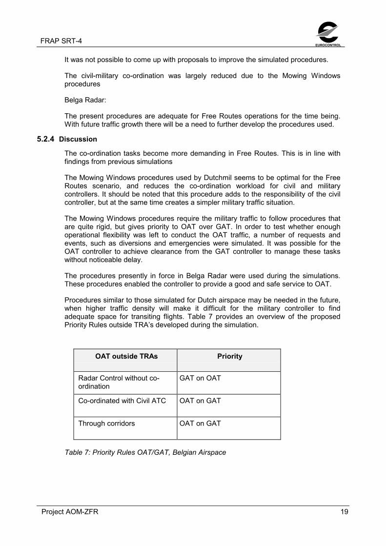
Procedures similar to those simulated for Dutch airspace may be needed in the future,when higher traffic density will make it difficult for the military controller to findadequate space for transiting flights. Table 7 provides an overview of the proposedPriority Rules outside TRA’s developed during the simulation.
OAT outside TRAs Priority
Radar Control without co-ordination
GAT on OAT
Co-ordinated with Civil ATC OAT on GAT
Through corridors OAT on GAT
Table 7: Priority Rules OAT/GAT, Belgian Airspace
EUROCONTROLFRAP SRT-4
Project AOM-ZFR20
5.3 OBJECTIVE 3
Analyse the effect on TRA operation in FRA, including tactical activation anddeactivation of TRAs and the need for distribution of airspace status data.
5.3.1 Recordings
None
5.3.2 Questionnaires
Figure 12: Impact of TRAs
Figure 13: Flightplanning
Activation of segregated airspace has a bigger impact on capacity in Free Routes than with a
route structure
0123456
Strong
ly dis
agree
Disagre
e
Slightl
y Disa
gree
Slightl
y agre
eAgre
e
Strong
ly ag
ree
No.
of r
eplie
s
Civil controllersMilitary controllers
Operators should send flightplans that circumnavigates segregated airspace. Shortcuts
can be made on a tactical basis if airspace situation permits
0123456789
Strong
ly dis
agree
Disagre
e
Slightl
y Disa
gree
Slightl
y agre
eAgre
e
Strong
ly ag
ree
No.
of r
eplie
s
Civil controllersMilitary controllers
FRAP SRT-4 EUROCONTROL
Project AOM-ZFR 21
5.3.3 De-briefings
Military controllers found it most convenient that flight plans for civil flights werecircumnavigating active TRAs. Not all civil controllers agreed to this, mainly becausethey did not trust that the operators could do this correctly due to ad hoc changes inactivation times, cancellation due to weather etc.
The need for real-time updates of airspace status, not only within your own FIR, butalso for surrounding areas, was considered very important.
In periods with many TRAs active, Free Routes traffic streams are almost identical tothe fixed routes.
The co-ordination of GAT through TRAs is adding to the workload on the GAT and theOAT controller.
The benefit of Free Routes during the periods where many TRAs were active wasconsidered to be very limited in the simulated airspace.
5.3.4 Discussion
GAT flight plans should keep the flights clear of TRAs planned to be active. Thissubject has been discussed during several simulations, and it seems that the bestsolution, for the civil as well as the military operations, would be to adopt this practise.
It would require a very accurate and updated picture of the planned TRA activation,available for airline operators to implement this procedure. A notification 24 hours inadvance seems not to be accurate enough for this purpose. In addition the presentairspace status for neighbouring FIRs should be available, to enable the controller totake tactical measures without causing new problem in downstream sectors.
The workload related to co-ordination of flights through TRAs will be reduced by theimplementation of System Supported Civil-military Co-ordination, but it is still possiblethat GAT controllers, when busy, will omit to co-ordinate through the TRAs, and let theflights follow their flight planned routes around the TRAs to reduce workload.
The question about deactivation and reactivation of TRAs was raised. From civil side,even small timeslots where TRAs were deactivated were considered a benefit, andcould help solving tactical problems. The workload of deactivating and reactivatingTRAs is small. The important thing is to assure that everybody has the same currentinformation.
5.4 OBJECTIVE 4
Evaluate the possibilities for GAT traffic to transit TRA’s including workload.
5.4.1 RecordingsNone
5.4.2 QuestionnairesNone
EUROCONTROLFRAP SRT-4
Project AOM-ZFR22
5.4.3 De-briefings
In order to reduce the periods where TRAs are segregated, the following possibilitiesfor GAT to transit TRAs where proposed for Belgian Airspace.
• Civil traffic controlled by the GAT or by the OAT service provider depending activitywithin the TRA
• Civil flights following the Free Routes track or through a fixed corridor through theTRA.
If the operations within the TRAs managed by an air defence unit, there would be nopossibility to cross the TRA for GAT traffic.
5.4.4 Discussion
In Dutch airspace this it is not possible for GAT to penetrate active TRAs.
Procedures that allow civil flights to cross active TRA are in force in other countries inEurope.
The workload associated with the co-ordination task is considered the same as thetactical workload when circumnavigating a TRA, but from a workload distribution pointof view, it is in general an advantage to take work away from the EXC and leave thetask with the PLC.
The proposed possibility for crossings to take place under control of the OAT controllercould be an interesting way to allow crossings in periods where it normally not wouldbe possible. It was also proposed that TRA penetration could be more acceptable forthe military part if all penetrating flights were following the same route within the TRA.Table 7 shows a proposal for priority Rules for TRA operations
OAT controlledby
GAT TRAPenetration
GAT controlledby
Priority
Mil ATC On Free Routestrack
Civil ATC GAT on OAT
Mil ATC Establishedcorridor
Mil ATC No priority
Mil ATC On Free Routestrack
Civil ATC GAT on OAT
Mil ATC Establishedcorridor
Mil ATC No priority
Air Defence No penetration N/a N/a
Table 8: Priority Rules for TRA Penetrations
FRAP SRT-4 EUROCONTROL
Project AOM-ZFR 23
5.5 OBJECTIVE 5
Identify additional requirements for system support for military operations in FreeRoutes Airspace
5.5.1 Recordings
Figure 14: Recording, Average use of telephone
Figure 15: Recording, Average use of radio
Average telephone usage, all Org. 1 exercises
012345678
BN/PLC BNEXC BS/PLC BS/EXC
Controller
Min
utes
pr.
exer
cise
Advanced scenarioBasic scenario
Average radio usage, all Org. 1 exercises
1313.5
14
14.5
1515.5
1616.5
BN/EXE BS/EXE
Controller
Min
utes
pr.
hour
Advanced scenarioBasic scenario
EUROCONTROLFRAP SRT-4
Project AOM-ZFR24
Estimated Workload (ISA)Agregation of exercises 040900A,040900C,060900B,060900C
Source : Isa AnalysisVery High Norma Low Very No
%
0
10
20
30
40
50
60
70
80
90
100
BS/PLC BS/EXC MS/PLC BN/PLC MW/EXC BN/EXC MW/PLC
Figure 16: ISA, Perceived Workload, Basic System Scenario
Estimated Workload (ISA)Agregation of exercises 050900A,050900C,080900B,080900C
Source : Isa AnalysisVery High Norma Low Very No
%
0
10
20
30
40
50
60
70
80
90
100
BS/PLC BS/PLC MS/PLC BN/PLC MW/EXC BN/EXC MW/PLC
Figure 17: ISA, Perceived workload, Advanced System Scenario
FRAP SRT-4 EUROCONTROL
Project AOM-ZFR 25
5.5.2 Questionnaires
Figure 18: Question, MTCD
5.5.3 De-briefings
The full exchange of flight plan data and controller inputs such as cleared level,heading etc. was considered useful by the controllers, especially in a Free Routesenvironment, where flight paths are more difficult to anticipate for the OAT controller,this was considered a necessity.
The System Supported Civil-Military Co-ordination was well received by the controllers,who found it easy to use. The reduction in telephone co-ordination was clear.
The controllers expressed a need for a real-time update on airspace status within aarea covering their own FIR plus neighbouring FIRs.
5.5.4 Discussion
Figure 14 shows, as expected, a reduction in the use of telephone when mowing fromthe Basic System Scenario to the Advanced System Scenario. The ISA scores inFigures 16 and 17 support the finding, where a small reduction in workload is recordedwhen introducing the Advanced System Scenario.
It is a finding in several simulations that there in Free Routes will be a need for real-time update of airspace status in neighbouring FIRs in order to enable the controller toplan ahead when implementing tactical measures. This exists between some ACCstoday, but will have to be more dynamic, including the actual and planned use of R&DAreas and TRAs.
Introduction of MTCD will be necessary before the introduction of Free Routes
0
1
2
3
4
5
6
Strong
ly dis
agree
Disagre
e
Slightl
y Disa
gree
Slightl
y agre
eAgre
e
Strong
ly ag
ree
No.
of r
eplie
s
Civil controllersMilitary controllers
EUROCONTROLFRAP SRT-4
Project AOM-ZFR26
6. CONCLUSIONS
Assess the effect of FRA on different types of OAT operations under various sets ofprocedures using different levels of system support.
• FRA has only a minor impact on OAT operations in the simulated airspace.• FRA lead to a small increase in the OAT controllers workload.Develop and assess different sets of procedures for civil-military co-operation,including priority rules in FRA with respect to workload, efficiency, safety, taking intoconsideration the effects of RVSM reduction in controller workload was demonstrated.
• Co-ordination becomes more demanding in FRA.• The procedures presently in force in Belgian airspace are sufficient to support FRA
operations with the present workload.• When traffic density increases, there will be a need to modify procedures presently
used in Belgian airspace, even without implementation of FRAC• The Moving Windows procedure introduced in Dutch Airspace seems to be ideal for
FRA in an RVSM scenarioAnalyse the effect on TRA operation in FRA, including tactical activation anddeactivation of TRAs and the need for distribution of airspace status data.
• When TRAs are active, GAT benefit of FRA is very limited in the simulatedairspace.
• GAT flight plans should be made to circumnavigate TRAsEvaluate the possibilities for GAT traffic to transit TRA’s including workload.
• Procedures for GAT penetration of active TRAs should be established if possible.Identify additional requirements for system support for military operations in FreeRoutes Airspace.
• Full exchange of flight plan data and controller intentions should be implemented• System Supported Civil-military Co-ordination is reducing workload.
FRAP SRT-4 EUROCONTROL
Project AOM-ZFR 27
7. RECOMMENDATIONS
The following additional studies should be carried out during the Validation Phase ofthe Eight-States Free Routes Project
1. Moving Windows procedure like the ones simulated for Dutch airspace in thissimulation should be considered for other areas of FRAC airspace.
2. Flexible rules for utilisation of TRAs should be considered.
3. Development of a tool providing real-time status of segregated airspacethroughout the Eight States should be initiated and implemented in ACCs.
4. A tool that will allow Airline operators to submit flight plans that took active TRAsand R&D Areas into consideration should be developed.