FLUID COOLING | Shell & T ube EK Series W ATERCOOLEDEKCOPPER & STEEL CONSTRUCTION Features n Compact Size n High Efficiency Finned Bundle Design n Low Cost n Optional Patented Built -in Surge-Cushion ® Relief Bypass n 3/16” Tube Size n Heat Removal up to 400 Horsepower (300 kW) n Oil Flow rates u p to 80 U.S. GPM (300 Liters/min.) n Large Oil Connections for Minimum Entering and Exiting Flow Restriction n Removable End Bonnets for easy tube cleaning n Mounting Brackets Designed so that Cooler can be Rotated in 90° Increments n High Pressure Ratings n Complete Line of Accessories Available Materials ShellSteel Tube SheetsSteel Baff lesSteel Mounting BracketsSteel GasketsNitrile Rubber/Cellulose Fiber NameplateAluminum Foil Tubes Copper FinsAluminum End CapsGrey Iron Ratings Operating Pressure/Shell side500 psi Operating Pressure/Tubeshell side150 psi Operating Temperature250° F Incorrect installation can cause premature failure. Maximum Flow Rates Shell Tube Side GPM Unit Side One Two Four Size GPM Pass Pass Pass 500 20 13 6 N/A 700 60 24 12 6 1000 80 56 28 14 Surge-Cushion (Option) The SURGE-CUSHION ® is a protective device (patented) designed to internally bypass a portion of the oil flow during cold start conditions, or when sudden flow surges temporarily exceed the maximum flow allowed for a given cooler. This device may replace an external bypass valve, but it is not intended to bypass the total oil flow. [email protected] p. 888-226-8522 . 805-484-0049 www.SouthwestThermal.com
Surge-Cushion ® Relief Bypassn 3/16” Tube Sizen Heat Removal up to 400 Horsepower
(300 kW)n Oil Flow rates up to 80 U.S. GPM (300
Liters/min.)n Large Oil Connections for Minimum
Entering and Exiting Flow Restrictionn Removable End Bonnets for easy tube cleaning
n Mounting Brackets Designed so that Cooler can be Rotated in 90°Increments
n High Pressure Ratingsn Complete Line of Accessories Available
MaterialsShell Steel
Tube Sheets Steel
Baff les Steel
Mounting Brackets Steel
Gaskets Nitrile Rubber/Cellulose Fiber
Nameplate Aluminum Foil
Tubes Copper
Fins Aluminum
End Caps Grey Iron
RatingsOperating Pressure/Shell side 500 psi
Operating Pressure/Tubeshell side 150 psi
Operating Temperature 250° F
Incorrect installation can cause premature failure.
Maximum Flow Rates
Shell Tube Side GPM Unit Side One Two Four Size GPM Pass Pass Pass
500 20 13 6 N/A
700 60 24 12 6
1000 80 56 28 14
Surge-Cushion (Option)The SURGE-CUSHION® is a protective device(patented) designed to internally bypassa portion of the oil ow during cold startconditions, or when sudden ow surgestemporarily exceed the maximum ow allowedfor a given cooler. This device may replace anexternal bypass valve, but it is not intended tobypass the total oil ow.
[email protected] p. 888-226-8522 . 805-484-0049 www.SouthwestThermal.com
8/10/2019 EK Series
http://slidepdf.com/reader/full/ek-series 2/7
8/10/2019 EK Series
http://slidepdf.com/reader/full/ek-series 3/7
E K
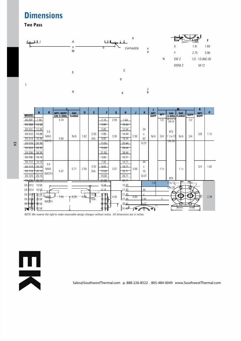
DimensionsTwo Pass
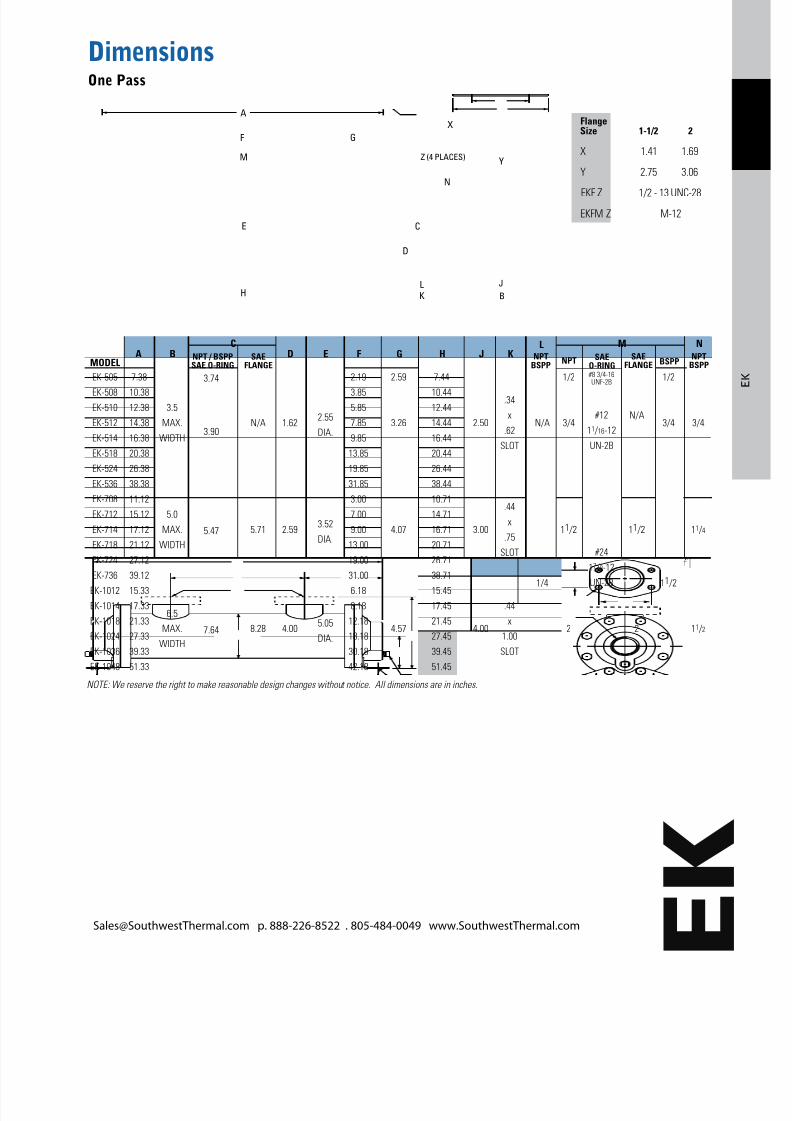
Flange Size 1-1/2 2
X 1.41 1.69
Y 2.75 3.06
EKF Z 1/2 - 13 UNC-28
EKFM Z M-12
D
C
G
E
FM
A
H
L
K
P
N
JB
X
YZ (4 PLACES)
A B SAEFLANGE SAEO-RING
SAEFLANGE BSPP
C
D E F G H J K P
L
NPT
M
NPTBSPP
N
NPTBSPPNPT / BSPPSAE O-RING
MODEL
EK-505
EK-508
EK-510
EK-512
EK-514
EK-518
EK-524
EK-536
EK-708
EK-712
EK-714
EK-718
EK-724
EK-736
EK-1012
EK-1014
EK-1018
EK-1024
EK-1036
EK-1048
7.38
10.38
12.38
14.38
16.38
20.38
26.38
38.38
10.19
14.19
16.19
20.19
26.19
39.19
14.58
16.58
20.58
26.58
38.58
50.58
2.19
3.85
5.85
7.85
9.85
13.85
19.85
31.85
3.00
7.00
9.00
13.00
19.00
31.00
6.18
8.18
12.18
18.18
30.18
42.18
7.44
10.44
12.44
14.44
16.44
20.44
26.44
38.44
10.71
14.71
16.71
20.71
26.71
38.71
15.45
17.45
21.45
27.45
39.45
51.45
3.5
MAX.
WIDTH
5.0
MAX.
WIDTH
6.5
MAX.
WIDTH
2.55
DIA.
3.52
DIA.
5.05
DIA.
3.74
3.90
5.47
7.64
N/A
5.71
8.28
1.62
2.59
4.00
2.59
3.26
3.57
4.45
2.50
3.00
4.00
1.12
1.62
2.38
.34
x
.62
SLOT
.44
x
.75
SLOT
.44
x
1.00
SLOT
N/A
1/4
1/2
3/4
11 / 2
2
1/2
3/4
11 / 2
#8 3/4-16UNF-2B
#12
11 / 16-12
UN-2B
#24
17 /8-12
UN-2B
N/A
11 / 2
2
3/8
3/4
1.0
NOTE: We reserve the right to make reasonable design changes without notice. All dimensions are in inches.
[email protected] p. 888-226-8522 . 805-484-0049 www.SouthwestThermal.com
8/10/2019 EK Series
http://slidepdf.com/reader/full/ek-series 4/7
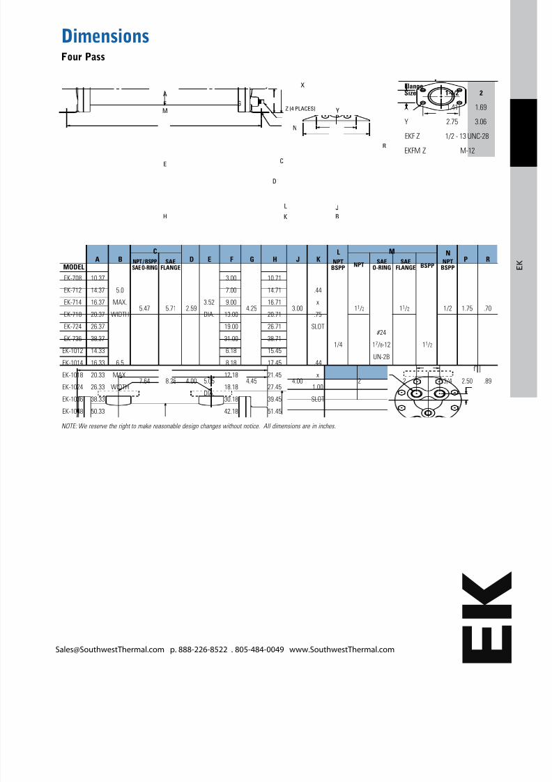
DimensionsFour Pass
Flange Size 1-1/2 2
X 1.41 1.69
Y 2.75 3.06
EKF Z 1/2 - 13 UNC-28
EKFM Z M-12
P
J
B
R
N
L
D
C
GF
A
M
E
H K
X
YZ (4 PLACES)
MODELA B NPT / BSPP
SAE O-RINGSAE
FLANGESAE
O-RINGSAE
FLANGE BSPP
C
D E F G H J K P
L
NPT R
M
NPTBSPP
N
EK-708
EK-712
EK-714
EK-718
EK-724
EK-736
EK-1012
EK-1014
EK-1018
EK-1024
EK-1036
EK-1048
10.37
14.37
16.37
20.37
26.37
38.37
14.33
16.33
20.33
26.33
38.33
50.33
3.00
7.00
9.00
13.00
19.00
31.00
6.18
8.18
12.18
18.18
30.18
42.18
10.71
14.71
16.71
20.71
26.71
38.71
15.45
17.45
21.45
27.45
39.45
51.45
5.0
MAX.
WIDTH
6.5
MAX.
WIDTH
3.52
DIA.
5.05
DIA.
5.47
7.64
5.71
8.28
2.59
4.00
4.25
4.45
3.00
4.00
.44
x
.75
SLOT
.44
x
1.00
SLOT
1/4
11 /2
2
#24
17 /8-12
UN-2B
11 /2
2
11 /2
1/2
3/4
1.75
2.50
.70
.89
NPTBSPP
NOTE: We reserve the right to make reasonable design changes without notice. All dimensions are in inches.
[email protected] p. 888-226-8522 . 805-484-0049 www.SouthwestThermal.com
8/10/2019 EK Series
http://slidepdf.com/reader/full/ek-series 5/7
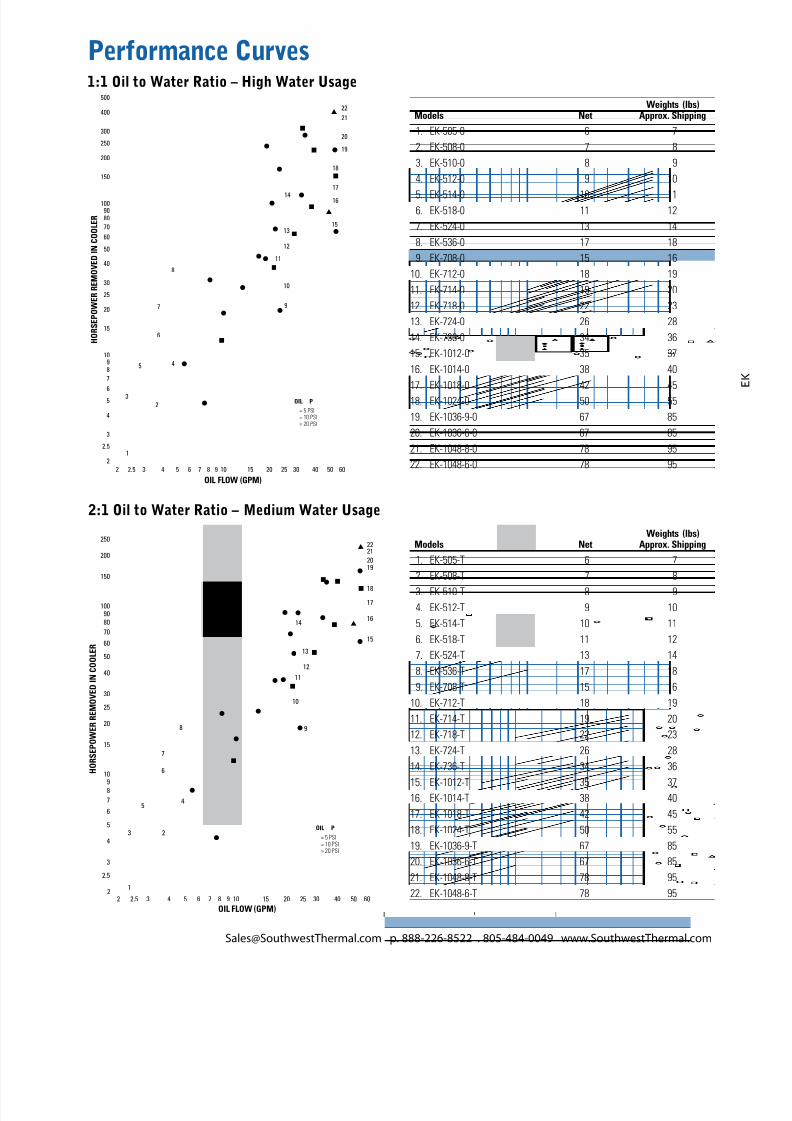
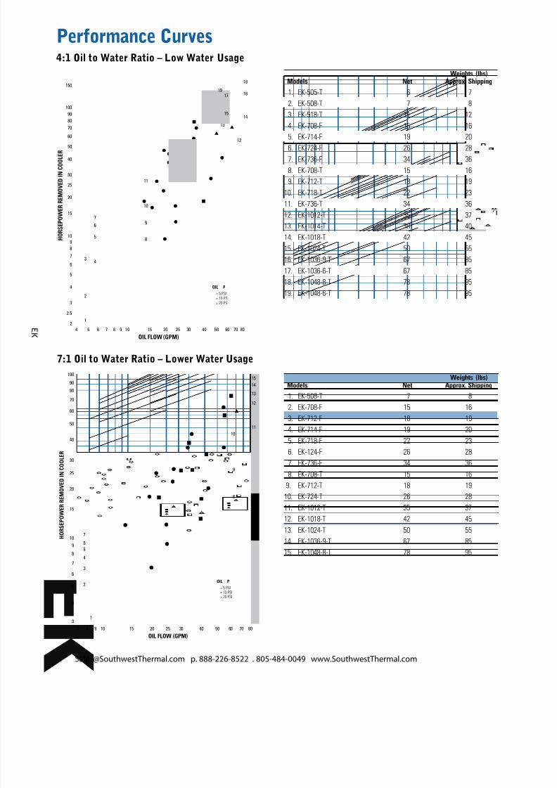
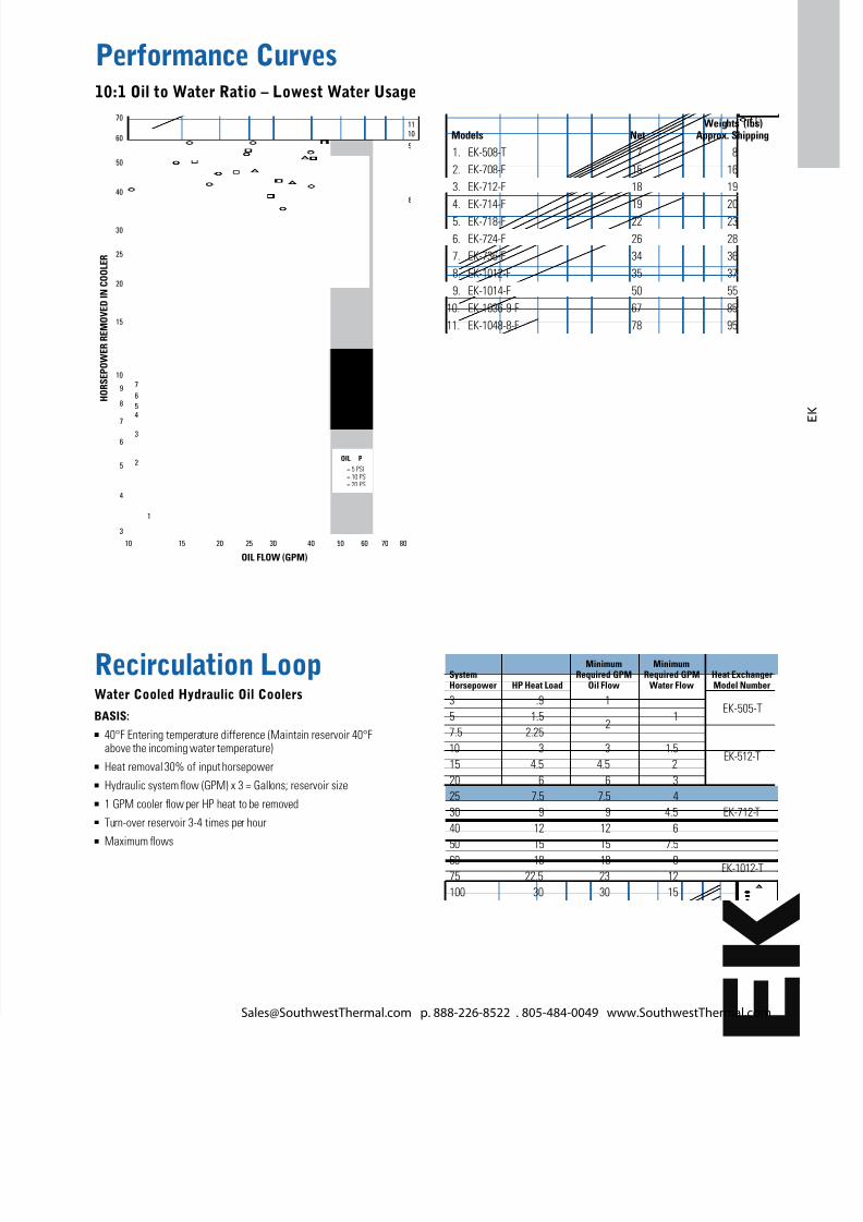
Performance Curves1:1 Oil to Water Ratio – High Water Usage
above the incoming water temperature)n Heat removal 30% of input horsepowern Hydraulic system ow (GPM) x 3 = Gallons; reservoir sizen 1 GPM cooler ow per HP heat to be removedn Turn-over reservoir 3-4 times per hourn Maximum ows
Minimum MinimumSystem Required GPM Required GPM Heat ExchangerHorsepower HP Heat Load Oil Flow Water Flow Model Number