ELECTRONICS FOR SPECIALISTS ELECTRONICS FOR SPECIALISTS ELECTRONICS FOR SPECIALISTS ELECTRONICS FOR SPECIALISTS BEDIENUNGSANLEITUNG INSTRUCTION MANUAL MODE D’EMPLOI ISTRUZIONI PER L’USO MANUAL DE INSTRUCCIONES INSTRUKCJA OBSŁUGI VEILIGHEIDSVOORSCHRIFTEN SIKKERHEDSOPLYSNINGER SÄKERHETSFÖRESKRIFTER TURVALLISUUDESTA ELA-Mischverstärker PA Mixing Amplifier PA-900 Bestell-Nr. • Order No. 17.1190
Transcript
ELECTRONICS FOR SPECIALISTS ELECTRONICS FOR SPECIALISTS ELECTRONICS FOR SPECIALISTS ELECTRONICS FOR SPECIALISTS
BEDIENUNGSANLEITUNG
INSTRUCTION MANUAL
MODE D’EMPLOI
ISTRUZIONI PER L’USO
MANUAL DE INSTRUCCIONES
INSTRUKCJA OBSŁUGI
VEILIGHEIDSVOORSCHRIFTEN
SIKKERHEDSOPLYSNINGER
SÄKERHETSFÖRESKRIFTER
TURVALLISUUDESTA
ELA-MischverstärkerPA Mixing Amplifier
PA-900Bestell-Nr. • Order No. 17.1190
2
ELECTRONICS FOR SPECIALISTS ELECTRONICS FOR SPECIALISTS ELECTRONICS FOR SPECIALISTS ELECTRONICS FOR SPECIALISTS
COM
OUTPUT
4Ω 70V 100V100 V
COM
OUTPUT
4Ω 70V 100V4Ω
COM
OUTPUT
4Ω 70V 100V4Ω
COM
OUTPUT
4Ω 70V 100V4Ω
COM
OUTPUT
4Ω 70V 100V100 V
+
-
100 V+
-
100 V+
-
100 V+
-
+
-
+
-
. . .
+
-
+
-
+
-
+
-
70 V+
-
70 V+
-
70 V+
-
. . .
4Ω30 W RMS
8Ω60 W RMS
4Ω120 W RMS
8Ω60 W RMS
4Ω30 W RMS
4Ω30 W RMS
max. Belastungmax. load120 W RMS
max. Belastungmax. load120 W RMS
4Ω30 W RMS
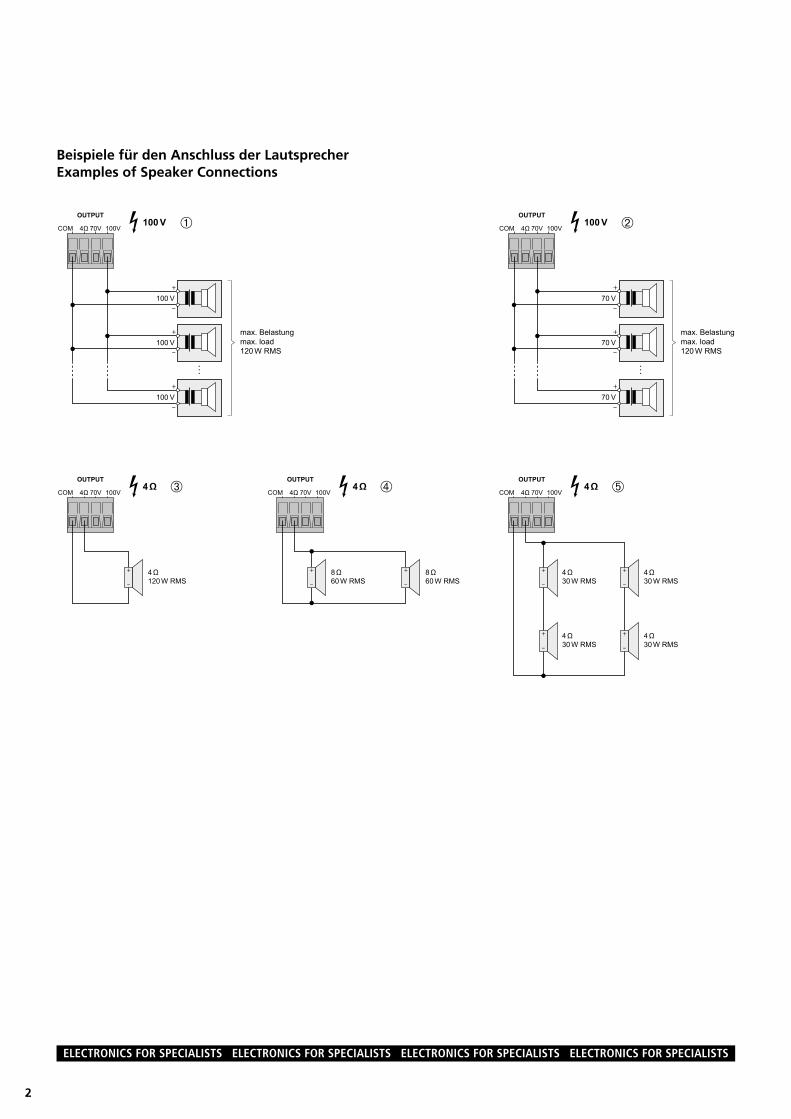
Beispiele für den Anschluss der LautsprecherExamples of Speaker Connections
➀
➂ ➃
➁
➄
ELECTRONICS FOR SPECIALISTS ELECTRONICS FOR SPECIALISTS ELECTRONICS FOR SPECIALISTS ELECTRONICS FOR SPECIALISTS
ELA-MischverstärkerBitte lesen Sie diese Anleitung vor dem Betrieb gründlich durch und heben Sie sie für ein spä-teres Nachlesen auf .
Die Lautsprecher dürfen nur von Perso-nen, die ausreichende Fachkenntnisse in der 100-V-Beschallungstechnik besitzen, ange-schlossen werden (Kap . 5 .1) . Die Bedienung des Verstärkers ist einfach und auf erwachsene Nichtfachleute ausgerichtet . Treten jedoch Fra-gen auf, wenden Sie sich bitte an Ihren Installa-teur oder Fachhändler .
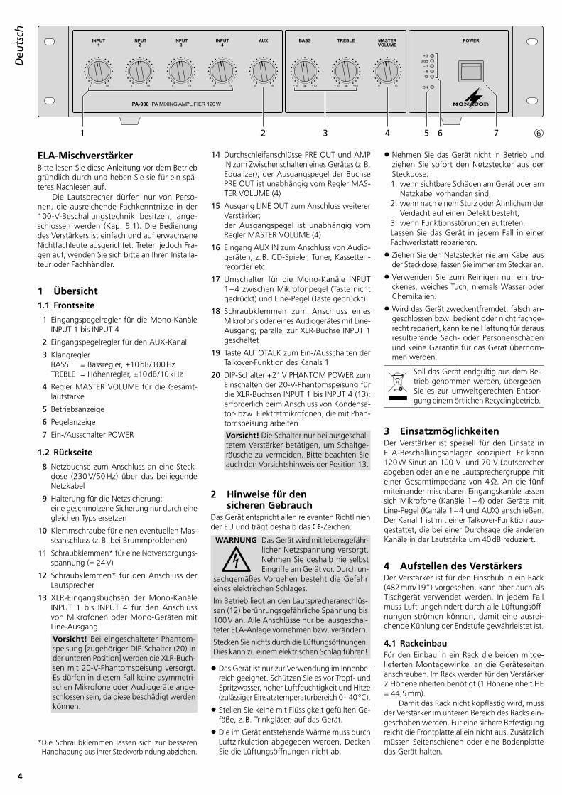
1 Übersicht1.1 Frontseite
1 Eingangspegelregler für die Mono-Kanäle INPUT 1 bis INPUT 4
2 Eingangspegelregler für den AUX-Kanal
3 Klangregler BASS = Bassregler, ±10 dB / 100 Hz TREBLE = Höhenregler, ±10 dB / 10 kHz
4 Regler MASTER VOLUME für die Gesamt-lautstärke
5 Betriebsanzeige
6 Pegelanzeige
7 Ein- /Ausschalter POWER
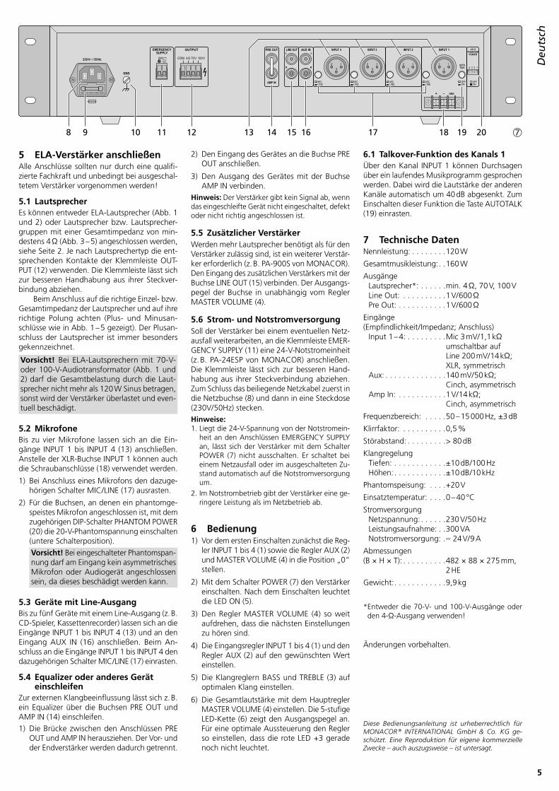
1.2 Rückseite
8 Netzbuchse zum Anschluss an eine Steck-dose (230 V/ 50 Hz) über das beiliegende Netzkabel
9 Halterung für die Netzsicherung; eine geschmolzene Sicherung nur durch eine gleichen Typs ersetzen
10 Klemmschraube für einen eventuellen Mas-seanschluss (z . B . bei Brummproblemen)
11 Schraubklemmen* für eine Notversorgungs-spannung ( 24 V)
12 Schraubklemmen* für den Anschluss der Lautsprecher
13 XLR-Eingangsbuchsen der Mono-Kanäle INPUT 1 bis INPUT 4 für den Anschluss von Mikrofonen oder Mono-Geräten mit Line-Ausgang
Vorsicht! Bei eingeschalteter Phantom-speisung [zugehöriger DIP-Schalter (20) in der unteren Position] werden die XLR-Buch-sen mit 20-V-Phantomspeisung versorgt . Es dürfen in diesem Fall keine asymmetri-schen Mikrofone oder Audio geräte ange-schlossen sein, da diese beschädigt werden können .
* Die Schraubklemmen lassen sich zur besseren Handhabung aus ihrer Steckverbindung abziehen .
14 Durchschleifanschlüsse PRE OUT und AMP IN zum Zwischenschalten eines Gerätes (z . B . Equalizer); der Ausgangspegel der Buchse PRE OUT ist unabhängig vom Regler MAS-TER VOLUME (4)
15 Ausgang LINE OUT zum Anschluss weiterer Verstärker; der Ausgangspegel ist unabhängig vom Regler MASTER VOLUME (4)
16 Eingang AUX IN zum Anschluss von Audio-geräten, z . B . CD-Spieler, Tuner, Kassetten-recorder etc .
17 Umschalter für die Mono-Kanäle INPUT 1 – 4 zwischen Mikrofonpegel (Taste nicht gedrückt) und Line-Pegel (Taste gedrückt)
18 Schraubklemmen zum Anschluss eines Mikro fons oder eines Audiogerätes mit Line- Ausgang; parallel zur XLR-Buchse INPUT 1 geschaltet
19 Taste AUTOTALK zum Ein- /Ausschalten der Talkover-Funktion des Kanals 1
20 DIP-Schalter +21 V PHANTOM POWER zum Einschalten der 20-V-Phantomspeisung für die XLR-Buchsen INPUT 1 bis INPUT 4 (13); erforderlich beim Anschluss von Kondensa-tor- bzw . Elektretmikrofonen, die mit Phan-tomspeisung arbeiten
Vorsicht! Die Schalter nur bei ausgeschal-tetem Verstärker betätigen, um Schaltge-räusche zu vermeiden . Bitte beachten Sie auch den Vorsichtshinweis der Position 13 .
2 Hinweise für den sicheren Gebrauch
Das Gerät entspricht allen relevanten Richtlinien der EU und trägt deshalb das -Zeichen .
WARNUNG Das Gerät wird mit lebensgefähr-licher Netzspannung versorgt . Nehmen Sie deshalb nie selbst Eingriffe am Gerät vor . Durch un-
sachgemäßes Vorgehen besteht die Gefahr eines elektrischen Schlages .
Im Betrieb liegt an den Lautsprecheranschlüs-sen (12) berührungsgefährliche Spannung bis 100 V an . Alle Anschlüsse nur bei ausgeschal-teter ELA-Anlage vornehmen bzw . verändern .
Stecken Sie nichts durch die Lüftungsöffnungen . Dies kann zu einem elektrischen Schlag führen!
• Das Gerät ist nur zur Verwendung im Innenbe-reich geeignet . Schützen Sie es vor Tropf- und Spritzwasser, hoher Luftfeuchtigkeit und Hitze (zulässiger Einsatztemperaturbereich 0 – 40 °C) .
• Stellen Sie keine mit Flüssigkeit gefüllten Ge-fäße, z . B . Trinkgläser, auf das Gerät .
• Die im Gerät entstehende Wärme muss durch Luftzirkulation abgegeben werden . Decken Sie die Lüftungsöffnungen nicht ab .
• Nehmen Sie das Gerät nicht in Betrieb und ziehen Sie sofort den Netzstecker aus der Steckdose:1 . wenn sichtbare Schäden am Gerät oder am
Netzkabel vorhanden sind,2 . wenn nach einem Sturz oder Ähnlichem der
Verdacht auf einen Defekt besteht,3 . wenn Funktionsstörungen auftreten .Lassen Sie das Gerät in jedem Fall in einer Fachwerkstatt reparieren .
• Ziehen Sie den Netzstecker nie am Kabel aus der Steckdose, fassen Sie immer am Stecker an .
• Verwenden Sie zum Reinigen nur ein tro-ckenes, weiches Tuch, niemals Wasser oder Chemikalien .
• Wird das Gerät zweckentfremdet, falsch an-geschlossen bzw . bedient oder nicht fachge-recht repariert, kann keine Haftung für daraus resultierende Sach- oder Personenschäden und keine Garantie für das Gerät übernom-men werden .
Soll das Gerät endgültig aus dem Be-trieb genommen werden, übergeben Sie es zur umweltgerechten Entsor-gung einem örtlichen Recyclingbetrieb .
3 EinsatzmöglichkeitenDer Verstärker ist speziell für den Einsatz in ELA-Beschallungsanlagen konzipiert . Er kann 120 W Sinus an 100-V- und 70-V-Lautsprecher abgeben oder an eine Lautsprechergruppe mit einer Gesamtimpedanz von 4 Ω . An die fünf miteinander mischbaren Eingangskanäle lassen sich Mikrofone (Kanäle 1 – 4) oder Geräte mit Line-Pegel (Kanäle 1 – 4 und AUX) anschließen . Der Kanal 1 ist mit einer Talkover-Funktion aus-gestattet, die bei einer Durchsage die anderen Kanäle in der Lautstärke um 40 dB reduziert .
4 Aufstellen des VerstärkersDer Verstärker ist für den Einschub in ein Rack (482 mm / 19”) vorgesehen, kann aber auch als Tischgerät verwendet werden . In jedem Fall muss Luft ungehindert durch alle Lüftungsöff-nungen strömen können, damit eine ausrei-chende Kühlung der Endstufe gewährleistet ist .
4.1 RackeinbauFür den Einbau in ein Rack die beiden mitge-lieferten Montagewinkel an die Geräteseiten anschrauben . Im Rack werden für den Verstärker 2 Höheneinheiten benötigt (1 Höheneinheit HE = 44,5 mm) .
Damit das Rack nicht kopflastig wird, muss der Verstärker im unteren Bereich des Racks ein-geschoben werden . Für eine sichere Befestigung reicht die Frontplatte allein nicht aus . Zusätzlich müssen Seitenschienen oder eine Bodenplatte das Gerät halten .
5
Deu
tsch
2 1
3
USE ONLY WITH A 250V FUSE
230 V~ / 50 Hz
+ – GND
GND
24V COM 4Ω 70V 100VL
R
LINE OUT AUX INL
R
PRE OUT
AMP IN
OUTPUT INPUT 4 INPUT 3 INPUT 2 INPUT 1
AUTOTALK
+21 VPHANTOM
POWER
1234
OFFON
OFFON
MICLINE
MICLINE
MICLINE
MICLINE
EMERGENCY SUPPLY
2 1
3
2 1
3
2 1
3
8 9 10 11 12 13 14 15 16 17 18 19 20 ➆
5 ELA-Verstärker anschließenAlle Anschlüsse sollten nur durch eine qualifi-zierte Fachkraft und unbedingt bei ausgeschal-tetem Verstärker vorgenommen werden!
5.1 LautsprecherEs können entweder ELA-Lautsprecher (Abb . 1 und 2) oder Lautsprecher bzw . Lautsprecher-gruppen mit einer Gesamtimpedanz von min-destens 4 Ω (Abb . 3 – 5) angeschlossen werden, siehe Seite 2 . Je nach Lautsprechertyp die ent-sprechenden Kontakte der Klemmleiste OUT-PUT (12) verwenden . Die Klemmleiste lässt sich zur besseren Handhabung aus ihrer Steckver-bindung abziehen .
Beim Anschluss auf die richtige Einzel- bzw . Gesamtimpedanz der Lautsprecher und auf ihre richtige Polung achten (Plus- und Minusan-schlüsse wie in Abb . 1 – 5 gezeigt) . Der Plusan-schluss der Lautsprecher ist immer besonders gekennzeichnet .
Vorsicht! Bei ELA-Lautsprechern mit 70-V- oder 100-V- Audiotransformator (Abb . 1 und 2) darf die Gesamtbelastung durch die Laut-sprecher nicht mehr als 120 W Sinus betragen, sonst wird der Verstärker überlastet und even-tuell beschädigt .
5.2 MikrofoneBis zu vier Mikrofone lassen sich an die Ein-gänge INPUT 1 bis INPUT 4 (13) anschließen . Anstelle der XLR-Buchse INPUT 1 können auch die Schraubanschlüsse (18) verwendet werden .
1) Bei Anschluss eines Mikrofons den dazuge-hörigen Schalter MIC / LINE (17) ausrasten .
2) Für die Buchsen, an denen ein phantomge-speistes Mikrofon angeschlossen ist, mit dem zugehörigen DIP-Schalter PHANTOM POWER (20) die 20-V-Phantomspannung einschalten (untere Schalterposition) .Vorsicht! Bei eingeschalteter Phantomspan-nung darf am Eingang kein asymmetrisches Mikrofon oder Audiogerät angeschlossen sein, da dieses be schädigt werden kann .
5.3 Geräte mit Line-AusgangBis zu fünf Geräte mit einem Line-Ausgang (z . B . CD-Spieler, Kassettenrecorder) lassen sich an die Eingänge INPUT 1 bis INPUT 4 (13) und an den Eingang AUX IN (16) anschließen . Beim An-schluss an die Eingänge INPUT 1 bis INPUT 4 den dazugehörigen Schalter MIC /LINE (17) einrasten .
5.4 Equalizer oder anderes Gerät einschleifen
Zur externen Klangbeeinflussung lässt sich z . B . ein Equalizer über die Buchsen PRE OUT und AMP IN (14) einschleifen .1) Die Brücke zwischen den Anschlüssen PRE
OUT und AMP IN herausziehen . Der Vor- und der Endverstärker werden dadurch getrennt .
2) Den Eingang des Gerätes an die Buchse PRE OUT anschließen .
3) Den Ausgang des Gerätes mit der Buchse AMP IN verbinden .
Hinweis: Der Verstärker gibt kein Signal ab, wenn das eingeschleifte Gerät nicht eingeschaltet, defekt oder nicht richtig angeschlossen ist .
5.5 Zusätzlicher VerstärkerWerden mehr Lautsprecher benötigt als für den Verstärker zulässig sind, ist ein weiterer Verstär-ker erforderlich (z . B . PA-900S von MONACOR) . Den Eingang des zusätzlichen Verstärkers mit der Buchse LINE OUT (15) verbinden . Der Ausgangs-pegel der Buchse in unabhängig vom Regler MASTER VOLUME (4) .
5.6 Strom- und NotstromversorgungSoll der Verstärker bei einem eventuellen Netz-ausfall weiterarbeiten, an die Klemmleiste EMER-GENCY SUPPLY (11) eine 24-V-Notstrom einheit (z . B . PA-24ESP von MONACOR) anschließen . Die Klemmleiste lässt sich zur besseren Hand-habung aus ihrer Steckverbindung abziehen . Zum Schluss das beiliegende Netzkabel zuerst in die Netzbuchse (8) und dann in eine Steckdose (230V/ 50Hz) stecken .Hinweise: 1 . Liegt die 24-V-Spannung von der Notstromein-
heit an den Anschlüssen EMERGENCY SUPPLY an, lässt sich der Verstärker mit dem Schalter POWER (7) nicht ausschalten . Er schaltet bei einem Netzausfall oder im ausgeschalteten Zu-stand automatisch auf die Notstromversorgung um .
2 . Im Notstrombetrieb gibt der Verstärker eine ge-ringere Leistung als im Netzbetrieb ab .
6 Bedienung1) Vor dem ersten Einschalten zunächst die Reg-
ler INPUT 1 bis 4 (1) sowie die Regler AUX (2) und MASTER VOLUME (4) in die Position „0“ stellen .
2) Mit dem Schalter POWER (7) den Verstärker einschalten . Nach dem Einschalten leuchtet die LED ON (5) .
3) Den Regler MASTER VOLUME (4) so weit aufdrehen, dass die nächsten Einstellungen zu hören sind .
4) Die Eingangsregler INPUT 1 bis 4 (1) und den Regler AUX (2) auf den gewünschten Wert einstellen .
5) Die Klangreglern BASS und TREBLE (3) auf optimalen Klang einstellen .
6) Die Gesamtlautstärke mit dem Hauptregler MASTER VOLUME (4) einstellen . Die 5-stufige LED-Kette (6) zeigt den Ausgangspegel an . Für eine optimale Aussteuerung den Regler so einstellen, dass die rote LED +3 gerade noch nicht leuchtet .
6.1 Talkover-Funktion des Kanals 1Über den Kanal INPUT 1 können Durchsagen über ein laufendes Musikprogramm gesprochen werden . Dabei wird die Lautstärke der anderen Kanäle automatisch um 40 dB abgesenkt . Zum Einschalten dieser Funktion die Taste AUTOTALK (19) einrasten .
Abmessungen(B × H × T): . . . . . . . . . .482 × 88 × 275 mm,
2 HE
Gewicht: . . . . . . . . . . . .9,9 kg
* Entweder die 70-V- und 100-V-Ausgänge oder den 4-Ω-Ausgang verwenden!
Änderungen vorbehalten .
Diese Bedienungsanleitung ist urheberrechtlich für MONACOR ® INTERNATIONAL GmbH & Co. KG ge-schützt. Eine Reproduktion für eigene kommerzielle Zwecke – auch auszugsweise – ist untersagt.
PA Mixing AmplifierPlease read these instructions carefully prior to operation and keep them for later reference .
Connection of the speakers (chapter 5 .1) requires adequate technical knowledge in 100 V PA technology and is to be made by experts only . Operation of the amplifier is easy, even for adults without any expert knowledge . How-ever, in case of any queries, please contact your installer or retailer .
1 Operating Elements and Connections
1.1 Front panel
1 Input level controls for the mono channels IN PUT 1 to INPUT 4
2 Input level control for the AUX channel
3 Tone controls BASS control ±10 dB / 100 Hz TREBLE control ±10 dB / 10 kHz
4 Control MASTER VOLUME for the total volume
5 POWER LED
6 Level indicators
7 POWER switch
1.2 Rear panel
8 Mains jack for connection to a mains socket (230 V/ 50 Hz) via the supplied mains cable
9 Support for the mains fuse; replace a blown fuse only by one of the same type
10 Clamping screw for a possible ground con-nection (e . g . in case of hum problems)
11 Terminals* for an emergency supply voltage ( 24 V)
12 Terminals* for the connection of the speakers
13 XLR input jacks of the mono channels INPUT 1 to INPUT 4 for connecting micro-phones or mono units with line outputCaution! With phantom power activated [corresponding DIP switch (20) in the lower position], the XLR jacks are supplied with 20 V phantom power . In this case, no un-balanced microphones or audio units must be connected as they may be damaged .
14 Feed-through connections PRE OUT and AMP IN for inserting a unit (e . g . equalizer); the output level of jack PRE OUT is inde-pendent of control MASTER VOLUME (4)
15 Output LINE OUT for connection of further amplifiers; the output level is independent of control MASTER VOLUME (4)
16 Input AUX IN for the connection of audio units, e . g . CD player, tuner, cassette re-corder, etc .
17 Selector switches for the mono channels INPUT 1 – 4 between microphone level (button not pressed) and line level (button pressed)
18 Terminals for connecting a microphone or an audio unit with line output; connected in parallel to the XLR jack INPUT 1
19 Button AUTOTALK for switching on / off the talk over function of channel 1
20 DIP switches +21 V PHANTOM POWER for switching on the 20 V phantom power for the XLR jacks INPUT 1 to INPUT 4 (13); required for connect ing capacitor or elec-tret microphones operating with phantom powerCaution! Only actuate the switches with the amplifier switched off to avoid swit-ching noise . Please observe the note under item 13 .
2 Safety NotesThe unit corresponds to all relevant directives of the EU and is therefore marked with .
WARNING The unit is supplied with haz-ardous mains voltage . Leave servic ing to skilled personnel only . Inexpert handling may cause an electric shock hazard .
During operation, there is a hazard of contact at the speaker connections (12) with a dan-gerous voltage up to 100 V . Always switch of the PA system before making or changing any connections .
Do not insert anything into the air vents! This could result in an electric shock .
• The unit is suitable for indoor use only . Protect it against dripping water and splash water, high air humidity, and heat (admissible am-bient temperature range 0 – 40 °C) .
• Do not place any vessels filled with liquid, e . g . drinking glasses, on the unit .
• The heat being generated in the unit must be dissipated by air circulation . Therefore, never cover the air vents .
• Do not set the unit into operation, and im-mediately disconnect the mains plug from the mains socket if
1 . there is visible damage to the unit or to the mains cable,
2 . a defect might have occurred after a drop or similar accident,
3 . there are malfunctions .The unit must in any case be repaired by skilled personnel .
• Never pull the mains cable to disconnect the mains plug from the mains socket, always seize the plug .
• For cleaning only use a dry, soft cloth; never use chemicals or water .
• No guarantee claims for the unit and no liabil-ity for any resulting personal damage or mate-rial damage will be accepted if the unit is used for purposes other than originally intended, if it is not correctly connect ed or operated or if it is not repaired in an expert way .
If the unit is to be put out of operation defini tively, take it to a local recycling plant for disposal which is not harmful to the environment .
3 ApplicationsThe amplifier has especially been designed for use in PA systems . It can deliver 120 W RMS to 100 V and 70 V speakers or to a speaker group with a total impedance of 4 Ω . Microphones (channels 1 – 4) or units with line level (channels 1 – 4 and AUX) can be connected to the five input channels which can be mixed with one another . Channel 1 is equipped with a talkover function which attenuates the volume of the other channels by 40 dB in case of an announce-ment .
4 Setting up the AmplifierThe amplifier has been designed for installation into a rack (482 mm / 19”), however, it can also be used as a table top unit . In any case, air must be allowed to pass freely through all air vents to ensure sufficient cooling of the power amplifier .
4.1 Rack installationFor rack installation, screw the two supplied mount ing brackets to the sides of the unit . In the rack, 2 rack spaces are required for the am-plifier (1 rack space = 44 .45 mm) .
To prevent top-heaviness of the rack, the amplifier must be inserted into the lower part of the rack . The front panel alone will not be able to secure the unit . Side rails or a base plate must additionally be provided .
EnglishEnglish Page
* The screw terminals can be removed from their plug-in connections for better handling .
7
English
2 1
3
USE ONLY WITH A 250V FUSE
230 V~ / 50 Hz
+ – GND
GND
24V COM 4Ω 70V 100VL
R
LINE OUT AUX INL
R
PRE OUT
AMP IN
OUTPUT INPUT 4 INPUT 3 INPUT 2 INPUT 1
AUTOTALK
+21 VPHANTOM
POWER
1234
OFFON
OFFON
MICLINE
MICLINE
MICLINE
MICLINE
EMERGENCY SUPPLY
2 1
3
2 1
3
2 1
3
8 9 10 11 12 13 14 15 16 17 18 19 20 ➆
5 Connecting the PA AmplifierAll connections should only be made by skilled personnel and with the amplifier switched off .
5.1 SpeakersIt is possible to connect either PA speakers (figs . 1 and 2) or speakers /speaker groups with a total impedance of at least 4 Ω (figs . 3 – 5), see page 2 . Depending on the speaker type, use the corresponding contacts of the terminal strip OUTPUT (12) . The terminal strip can be removed from its plug-in connection for better handling .
When connecting, observe the correct individual or total impedance of the speakers and their correct polarity (positive and negative connections as shown in figs . 1 – 5) . The positive connection of the speakers is always especially coded .
Caution! With PA speakers with a 70 V or 100 V audio transformer (figs . 1 and 2), the total load by the speak ers must not exceed 120 W RMS, otherwise the amplifier will be overloaded and possibly damaged .
5.2 MicrophonesUp to four microphones may be connected to the inputs INPUT 1 to INPUT 4 (13) . Instead of the XLR jack INPUT 1, also the terminals (18) may be used .
1) When connecting a microphone, unlock the corresponding switch MIC / LINE (17) .
2) For the jacks to which a phantom-powered microphone is connected: Use the corre-sponding DIP switch PHANTOM POWER (20) to switch on the 20 V phantom power (switch in the lower position) .Caution! When the phantom power is switched on, no unbalanced microphone or audio unit must be connected to the input; these units may be damaged .
5.3 Units with line outputUp to five units with a line output (e . g . CD player, cas sette recorder) can be connected to the inputs INPUT 1 to INPUT 4 (13) and to the input AUX IN (16) . When connecting to the in-puts INPUT 1 to INPUT 4, lock the corresponding switch MIC / LINE (17) .
5.4 Inserting an equalizer or another unit
For external effects on the sound, an equalizer, for example, can be inserted via the jacks PRE OUT and AMP IN (14) .
1) Remove the jumper between the connections PRE OUT and AMP IN . Thus, the preamplifier and the power amplifier are separated .
2) Connect the input of the unit to the jack PRE OUT .
3) Connect the output of the unit to the jack AMP IN .
Note: The amplifier does not emit a signal if the unit inserted is not switched on, if it is defective or not correctly connected .
5.5 Additional amplifierIf the number of the required speakers is higher than the number admissible for the amplifier, an additional amplifier will be required (e . g . MONACOR PA-900S) . Connect the input of the additional amplifier to the jack LINE OUT (15) . The output level of the jack is independent of the control MASTER VOLUME (4) .
5.6 Power supply and emergency power supply
For continued operation of the amplifier after a possible mains failure, connect a 24 V emergency power supply unit (e . g . MONACOR PA-24ESP) to the terminal strip EMERGENCY SUPPLY (11) . The terminal strip can be removed from its plug-in connection for better handling . Finally connect the supplied mains cable to the mains jack (8) first and then to a mains socket (230V/ 50Hz) .Notes: 1 . If the 24 V voltage from the emergency power
unit is available at the terminals EMERGENCY SUPPLY, the amplifier cannot be switched off with the switch POWER (7) . In case of a mains failure or if it is switched off, the amplifier will automatically switch to the emergency power supply .
2 . With emergency power supply, the amplifier will deliver less power than with mains supply .
6 Operation1) Prior to switching on the amplifier for the first
time, set the controls INPUT 1 to 4 (1) and the controls AUX (2) and MASTER VOLUME (4) to position “0” .
2) Switch on the amplifier with the POWER switch (7) . After switching-on, the LED ON (5) lights up .
3) Turn up the control MASTER VOLUME (4) so that the next adjustments are audible .
4) Adjust the input controls INPUT 1 to 4 (1) and the control AUX (2) to the desired value .
5) Adjust the tone controls BASS and TREBLE (3) to optimum sound .
6) Adjust the total volume with the main control MASTER VOLUME (4) . The 5-step LED row (6) indicates the output level . For an optimum level, adjust the control so that the red LED +3 does not yet light up .
6.1 Talkover function of channel 1Via channel INPUT 1, announcements can be made during a musical programme . Then the volume of the other channels is automatically attenuated by 40 dB . To switch on this function, lock the button AUTOTALK (19) .
Tone control Bass: . . . . . . . . . . . . . .±10 dB /100 Hz Treble: . . . . . . . . . . . .±10 dB /10 kHz
Phantom power: . . . . . .+20 V
Ambient temperature: .0 – 40 °C
Power supply Mains voltage: . . . . . .230 V/ 50 Hz Power consumption: . .300 VA Emergency power supply: . . . . . . . 24 V/ 9 A
Dimensions (W × H × D): . . . . . . . . .482 × 88 × 275 mm,
2 rack spaces
Weight: . . . . . . . . . . . .9 .9 kg
* Either use the 70 V and 100 V outputs or the 4 Ω output!
Subject to technical modification .
All rights reserved by MONACOR ® INTERNATIONAL GmbH & Co. KG. No part of this instruction manual may be reproduced in any form or by any means for any commercial use.
Amplificateur-Mixeur Public AdressVeuillez lire la présente notice avec attention avant le fonctionnement et conservez-la pour pouvoir vous y reporter ultérieurement .
Seules des personnes ayant des connais-sances suffisantes en ligne 100 V peuvent ins-taller les enceintes (chapitre 5 .1) . L’utilisation de l’amplificateur est simple et prévue pour des adultes non techniciens . Cependant, en cas de questions, contactez votre installateur ou re-vendeur .
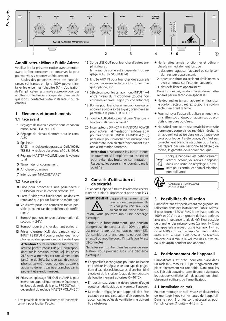
1 Eléments et branchements1.1 Face avant
1 Réglages de niveau d’entrée pour les canaux mono INPUT 1 à INPUT 4
2 Réglage de niveau d’entrée pour le canal AUX
3 Égaliseur BASS = réglage des graves, ±10 dB /100 Hz TREBLE = réglage des aigus, ±10 dB /10 kHz
4 Réglage MASTER VOLUME pour le volume total
5 Témoin de fonctionnement
6 Affichage du niveau
7 Interrupteur MARCHE /ARRET
1.2 Face arrière
8 Prise pour brancher à une prise secteur (230 V/ 50 Hz) via le cordon secteur livré
9 Porte-fusible ; tout fusible fondu ne doit être remplacé que par un fusible de même type
10 Vis d’arrêt pour une connexion masse pos-sible (p . ex . en cas de problèmes de ronfle-ment)
11 Bornes* pour une tension d’alimentation de secours ( 24 V)
12 Bornes* pour brancher des haut-parleurs
13 Prises d’entrée XLR des canaux mono INPUT 1 à INPUT 4 pour brancher des micro-phones ou des appareils mono à sortie Ligne
Attention ! Si l‘alimentation fantôme est activée [interrupteur DIP (20) correspon-dant sur la position inférieure], les prises XLR sont alimentées par une alimentation fantôme de 20 V . Dans ce cas, des micro-phones asymétriques ou des appareils audio ne doivent pas être branchés car ils peuvent être endommagés .
14 Prises de repiquage PRE OUT et AMP IN pour insérer un appareil (par exemple égaliseur) ; le niveau de sortie de la prise PRE OUT est in-dépendant du réglage MASTER VOLUME (4)
* Il est possible de retirer les bornes de leur empla-cement pour faciliter l’accès .
15 Sortie LINE OUT pour brancher d’autres am-plificateurs ; le niveau de sortie est indépendant du ré-glage MASTER VOLUME (4)
16 Entrée AUX IN pour brancher des appareils audio, par exemple lecteur CD, tuner, ma-gnétophone, etc .
17 Sélecteurs pour les canaux mono INPUT 1 – 4 entre niveau du microphone (touche non enfoncée) et niveau Ligne (touche enfoncée)
18 Bornes pour brancher un microphone ou un appareil audio à sortie Ligne ; branchées en parallèle à la prise XLR INPUT 1
19 Touche AUTOTALK pour allumer / éteindre la fonc tion talkover du canal 1
20 Interrupteurs DIP +21 V PHANTOM POWER pour activer l’alimentation fantôme 20 V pour les prises XLR INPUT 1 à INPUT 4 (13) ; nécessaire pour brancher des microphones condensateur ou électret fonctionnant avec une alimentation fantôme .
Attention ! Actionnez les interrupteurs uniquement si l‘amplificateur est éteint pour éviter des bruits de commutation . Respectez les conseils mentionnés dans le point 13 .
2 Conseils d’utilisation et de sécurité
Cet appareil répond à toutes les directives néces-saires de l’Union Européenne et porte donc le .
AVERTISSEMENT L’appareil est alimenté par une tension dangereuse . Ne touchez jamais l’intérieur car en cas de mauvaise manipu-
lation, vous pourriez subir une décharge électrique .
Pendant le fonctionnement, une tension dangereuse de contact de 100 V au plus est présente aux bornes haut-parleurs (12) . L’ensemble des branchements ne peut être effectué ou modifié que si l’installation PA est déconnectée .
Ne faites rien tomber dans les ouïes de ven-tilation, vous pourriez subir une décharge électrique !
• L’appareil n’est conçu que pour une utilisation en intérieur . Protégez-le de tout type de projec-tions d’eau, des éclaboussures, d’une humidité élevée et de la chaleur (plage de température de fonctionnement autorisée 0 – 40 °C) .
• En aucun cas, vous ne devez poser d’objet contenant du liquide ou un verre sur l’appareil .
• La chaleur dégagée par l’appareil doit être évacuée par une circulation d’air correcte . En aucun cas les ouïes de ventilation ne doivent être obstruées .
• Ne le faites jamais fonctionner et débran-chez-le immédiatement lorsque :1 . des dommages sur l’appareil ou sur le cor-
don secteur apparaissent .2 . après une chute ou accident similaire, vous
avez un doute sur l’état de l’appareil .3 . des défaillances apparaissent .Dans tous les cas, les dommages doivent être réparés par un technicien spécialisé .
• Ne débranchez jamais l’appareil en tirant sur le cordon secteur ; retirez toujours le cordon secteur en tirant la fiche .
• Pour nettoyer l’appareil, utilisez uniquement un chiffon sec et doux, en aucun cas de pro-duits chimiques ou d’eau .
• Nous déclinons toute responsabilité en cas de dommages corporels ou matériels résultants si l’appareil est utilisé dans un but autre que celui pour lequel il a été conçu, s’il n’est pas correctement branché ou utilisé ou s’il n’est pas réparé par une personne habi litée ; de même, la garantie deviendrait caduque .
Lorsque l’appareil est définitivement retiré du service, vous devez le déposer dans une usine de recyclage à proxi-mité pour contribuer à son élimination non polluante .
CARTONS ET EMBALLAGE PAPIER À TRIER
3 Possibilités d’utilisationL’amplificateur est spécialement conçu pour une utilisation dans des installations Public Adress . Il peut fournir 120 W RMS à des haut-parleurs 100 V et 70 V ou à un groupe de haut-parleurs avec une im pédance totale de 4 Ω . Il est possible de brancher des microphones (canaux 1 – 4) ou des appareils à niveau Ligne (canaux 1 – 4 et canal AUX) aux cinq canaux d’entrée mixables entre eux . Le canal 1 est doté d’une fonction talk over qui diminue le volume des autres ca-naux de 40 dB pendant une annonce .
4 Positionnement de l’appareilL’amplificateur est prévu pour être placé dans un rack (482 mm / 19”), il peut également être placé directement sur une table . Dans tous les cas, l’air doit pouvoir circuler librement via toutes les ouïes de ventilation afin de garantir un refroi-dissement suffisant de l’amplificateur .
4.1 Installation en rackPour un montage en rack, vissez les deux étriers de montage livrés sur les côtés de l’appareil . Dans le rack, 2 unités sont nécessaires pour l’amplificateur (1 unité = 44,5 mm) .
FrançaisFrançais Page
9
Fran
çais
2 1
3
USE ONLY WITH A 250V FUSE
230 V~ / 50 Hz
+ – GND
GND
24V COM 4Ω 70V 100VL
R
LINE OUT AUX INL
R
PRE OUT
AMP IN
OUTPUT INPUT 4 INPUT 3 INPUT 2 INPUT 1
AUTOTALK
+21 VPHANTOM
POWER
1234
OFFON
OFFON
MICLINE
MICLINE
MICLINE
MICLINE
EMERGENCY SUPPLY
2 1
3
2 1
3
2 1
3
8 9 10 11 12 13 14 15 16 17 18 19 20 ➆
Afin que le rack ne se renverse pas, vous devez placer l’amplificateur dans la partie infé-rieure du rack . Pour une fixation solide la plaque avant ne suffit pas . Utilisez également des rails latéraux ou une plaque inférieure pour le main-tenir correctement en place .
5 Branchement de l’amplificateur Public Adress
Tous les branchements ne doivent être effectués que par un technicien qualifié et uniquement lorsque l’amplificateur est éteint !
5.1 Haut-parleursIl est possible de brancher soit des haut-parleurs Public Adress (schémas 1 et 2) soit des haut-parleurs ou des groupes de haut-parleurs avec une impédance totale de 4 Ω au moins (schémas 3 – 5), voir page 2 . Selon le type de haut-parleur, utilisez les contacts correspondants des bornes OUTPUT (12) . Il est possible de retirer les bornes de leur emplacement pour faciliter l’accès .
Lors du branchement, veillez à respecter l’impédance individuelle ou l’impédance totale des haut-parleurs et leur polarité (branchements plus et moins comme indiqués sur les schémas 1 – 5) . Le branchement plus des haut-parleurs est toujours spécialement repéré .
Attention ! Dans le cas de haut-parleurs Public Adress avec transformateur audio 70 V ou 100 V (schémas 1 et 2), l’impédance totale par les haut-parleurs ne doit pas être supérieure à 120 W RMS, sinon l’amplificateur sera en sur-charge et pourrait être endommagé .
5.2 MicrophonesIl est possible de relier jusqu’à quatre micro-phones aux entrées INPUT 1 à INPUT 4 (13) . Il est également possible d’utiliser les bornes (18) à la place de la prise XLR INPUT 1 .
1) Lors du branchement d’un microphone, acti-vez le sélecteur correspondant MIC / LINE (17) .
2) Pour les prises auxquelles un microphone à alimentation fantôme est relié, activez l’ali-mentation fantôme 20 V (position inférieure de l’interrupteur) avec l’interrupteur DIP PHANTOM POWER (20) correspondant .
Attention ! Si l‘alimentation fantôme est activée, il ne faut pas brancher des micropho-nes asymétriques ou des appareils audio à l’entrée, car ils pourraient être endommagés .
5.3 Appareils à sortie LigneIl est possible de relier jusqu’à cinq appareils à sortie Ligne (p . ex . lecteur CD, magnétophone) aux entrées INPUT 1 à INPUT 4 (13) et à l’entrée AUX IN (16) . Si les entrées INPUT 1 à INPUT 4 sont reliées, activez le sélecteur correspondant MIC / LINE (17) .
5.4 Insérer un égaliseur ou un autre appareil
Pour une modification externe de la tonalité, il est possible d’insérer par exemple un égaliseur via les prises PRE OUT et AMP IN (14) .
1) Retirez le cavalier entre les connexions PRE OUT et AMP IN . Ainsi, le préamplificateur et l’amplificateur de puissance sont séparés .
2) Branchez l’entrée de l’appareil à la prise PRE OUT .
3) Reliez la sortie de l’appareil à la prise AMP IN .Conseil : L’amplificateur ne fournit pas de signal si l’appareil inséré n’est pas allumé, s’il est défectueux ou n’est pas correctement branché .
5.5 Amplificateur supplémentaireSi le nombre de haut-parleurs nécessaires est supérieur au nombre autorisé pour l’amplifica-teur, il convient de connecter un autre amplifica-teur (p . ex . PA-900S de MONACOR) . Reliez l’en-trée de l’amplificateur supplémentaire à la prise LINE OUT (15) . Le niveau de sortie de la prise est indépendant du réglage MASTER VOLUME (4) .
5.6 Alimentation secteur et alimentation de secours
Si l’amplificateur doit continuer à fonctionner en cas de coupure d’alimentation secteur, reliez une unité d’a limentation de secours 24 V (p . ex . PA-24ESP de MONACOR) aux bornes EMER-GENCY SUPPLY (11) . Il est possible de retirer les bornes de leur emplacement pour faciliter l’accès . Pour finir, reliez le cordon secteur livré tout d’abord à la prise (8) et puis à une prise secteur (230 V/ 50 Hz) .Conseils : 1 . Si une tension 24 V de l’unité d’alimentation de
secours est présente aux bornes EMERGENCY SUPPLY, l’amplificateur ne peut pas être éteint avec l’interrupteur POWER (7) . En cas de cou-pure de courant ou s’il est éteint, il commute automatiquement sur l’alimentation de secours .
2 . Avec un fonctionnement par courant de secours, l’amplificateur délivre une puissance moindre qu’avec un fonctionnement secteur .
6 Fonctionnement1) Avant la première mise sous tension, mettez
tout d’abord les réglages INPUT 1 à 4 (1) ainsi que les réglages AUX (2) et MASTER VOLUME (4) sur la position «0» .
2) Allumez l’amplificateur avec l’interrupteur POWER (7) . Après la mise sous tension, la LED ON (5) brille .
3) Tournez le réglage MASTER VOLUME (4) jusqu’à ce que les réglages suivants puissent être écoutés .
4) Mettez les réglages d’entrée INPUT 1 à 4 (1) et le réglage AUX (2) sur la valeur souhaitée .
5) Réglez les réglages de l’égaliseur BASS et TREBLE (3) pour obtenir une tonalité opti-male .
6) Réglez le volume total avec le réglage MAS-TER VOLUME (4) . La chaîne des LEDs à 5 niveaux indique le niveau de sortie . Pour un réglage optimal, tournez le réglage de telle sorte que la LED +3 rouge ne brille pas .
6.1 Fonction talkover du canal 1Via le canal INPUT 1, il est possible d’effectuer des annonces pendant la diffusion d’un pro-gramme de musique . Le volume des autres ca-naux est automatiquement diminué de 40 dB . Pour allumer cette fonc tion, enclenchez la touche AUTOTALK (19) .
7 Caractéristiques techniquesPuissance nominale : . . .120 WPuissance musique totale : . . . . . . . . . . . . . 160 W
Sorties Haut-parleurs* : . . . . .min . 4 Ω, 70 V, 100 V Line Out : . . . . . . . . . .1 V/ 600 Ω Pre Out : . . . . . . . . . . .1 V/ 600 Ω
* Utilisez soit les sorties 70 V et 100 V soit la sortie 4 Ω!
Tout droit de modification réservé .
Notice d’utilisation protégée par le copyright de MONACOR ® INTERNATIONAL GmbH & Co. KG. Toute reproduction même partielle à des fins commerciales est interdite.
Amplificatore mixer PAVi preghiamo di leggere attentamente le pre-senti istruzioni prima della messa in funzione e di conservarle per un uso futuro .
Gli altoparlanti devono essere collegati solo da persone con conoscenze sufficienti della tecnica di sonorizzazione con uscita audio 100 V (Cap . 5 .1) . L’impiego dell’amplificatore è semplice ed è previsto per non esperti adulti . Se avete delle domande, rivolgetevi al vostro installatore o rivenditore specializzato .
1 Elementi di comando e collegamenti
1.1 Pannello frontale
1 Regolatori del livello d’ingresso dei canali mono INPUT 1 a INPUT 4
2 Regolatore del livello d’ingresso del canale AUX
3 Regolatori toni BASS = regolatore bassi, ±10 dB /100 Hz TREBLE = regolatore alti, ±10 dB /10 kHz
4 Regolatore MASTER VOLUME per il volume globale
5 Spia di funzionamento
6 Indicazione livello
7 Interruttore on / off POWER
1.2 Pannello posteriore
8 Presa rete per il collegamento con una presa (230 V/ 50 Hz) servendosi del cavo rete in do-tazione
9 Supporto per il fusibile di rete; sostituire un fusibile difettoso solo con uno dello stesso tipo
10 Vite per un eventuale collegamento con la massa (p . es . nel caso di problemi di ronzio)
11 Morsetti* per un’alimentazione di emer-genza ( 24 V)
12 Morsetti* per il collegamento degli alto-parlanti
13 Prese d’ingresso XLR dei canali mono INPUT 1 a INPUT 4 per il collegamento di microfoni o di apparecchi mono con uscita Line
Attenzione! Se è attivata l’alimentazione phantom [il relativo DIP-switch (20) in posizione inferiore], le prese XLR vengono alimentate con l’alimentazione phantom 20 V . In questo caso non devono essere collegati microfoni o dispositivi audio sbi-lanciati in quanto possono subire dei danni .
* Per maggiore comodità, i morsetti possono essere sfilati dai connettori .
14 Contatti di attraversamento PRE OUT e AMP IN per inserire un apparecchio (p . es . equalizer); il livello d’uscita della presa PRE OUT è indi-pendente dal regolatore MASTER VOLUME (4)
15 Uscita LINE OUT per il collegamento di ulteriori amplificatori; il livello d’uscita è indipendente dal regola-tore MASTER VOLUME (4)
16 Ingresso AUX IN per il collegamento di apparecchi audio, p . es . lettore CD, tuner, registratore a cassette ecc .
17 Commutatori per i canali mono INPUT 1 – 4 fra livello microfono (tasto non premuto) e livello Line (tasto premuto)
18 Morsetti per il collegamento di un micro-fono o di un apparecchio audio con uscita Line; collegato in parallelo con la presa XLR INPUT 1
19 Tasto AUTOTALK per attivare / disattivare la funzione talkover del canale 1
20 DIP-switch +21 V PHANTOM POWER per attivare l’alimentazione phantom 20 V per le prese XLR INPUT 1 a INPUT 4 (13); è necessario quando si collegano microfoni a condensatore o a elettrete che funzionano con alimentazione phantom
Attenzione! Attivare gli switch solo con l’amplificatore spento, per evitare rumori di commutazione . Da notare anche la nota al punto 13 .
2 Avvertenze di sicurezzaL’apparecchio è conforme a tutte le direttive rilevanti dell’UE e pertanto porta la sigla .
AVVERTIMENTO Quest’apparecchio funziona con pericolosa tensione di rete . Non intervenire mai al suo interno; la manipolazione scorretta può provocare delle scariche pericolose .
Durante il funzionamento, ai contatti per gli altoparlanti (12) è presente una tensione fino a 100 V, pericolosa al contatto . Eseguire o mo-dificare tutti i collegamenti solo con l’impianto PA spento .
Non inserire oggetti nelle fessure d’aerazione . Altrimenti si potrebbe provocare una scarica elettrica!
• Lo strumento è previsto solo per l’uso all’in-terno di locali . Proteggerlo dall’acqua goccio-lante e dagli spruzzi d’acqua, da alta umidità dell’aria e dal calore (temperatura d’impiego ammessa fra 0 °C e 40 °C) .
• Non depositare sull’apparecchio dei conteni-tori riempiti di liquidi, p . es . bicchieri .
• Dev’essere garantita la libera circolazione del l’aria per dissipare il calore che viene pro-
dotto all’interno dell’apparecchio . Non coprire le fessure d’aerazione .
• Non mettere in funzione l’apparecchio e stac-care subito la spina rete se:1 . l’apparecchio o il cavo rete presentano dei
danni visibili;2 . dopo una caduta o dopo eventi simili sus-
siste il sospetto di un difetto;3 . l’apparecchio non funziona correttamente .Per la riparazione rivolgersi sempre ad un’of-ficina competente .
• Staccare il cavo rete afferrando la spina, senza tirare il cavo .
• Per la pulizia usare solo un panno morbido, asciut to; non impiegare in nessun caso pro-dotti chimici o acqua .
• Nel caso d’uso improprio, di collegamenti sba gliati, d’impiego scorretto o di riparazione scorretta non si assume nessuna responsabilità per eventuali danni consequenziali a persone o a cose e cessa ogni diritto di garanzia rela-tivo all’ apparecchio .
Se si desidera eliminare l’apparecchio definitivamente, consegnarlo per lo smaltimento ad un’istituzione locale per il riciclaggio .
3 Possibilità d’impiegoL’amplificatore è stato realizzato specialmente per l’impiego in impianti di sonorizzazione PA . Fornisce 120 Weff ad altoparlanti con ingresso audio 100 V e 70 V oppure ad un gruppo di altoparlanti con impedenza globale di 4 Ω . Ai cinque canali d’ingresso miscelabili fra di loro si possono collegare dei microfoni (canali 1 – 4) oppure apparecchi con livello Line (canali 1 – 4 e AUX) . Il canale 1 possiede una funzione Talkover, che durante un avviso riduce il volume degli altri canali di 40 dB .
4 Collocamento dell’amplificatoreL’amplificatore è previsto per il montaggio in un rack (482 mm / 19”), ma può essere collocato anche su un tavolo . In ogni caso deve essere garantita la libera circolazione dell’aria attra-verso le fessure di aerazione per ottenere una raffreddamento sufficiente dello stadio finale .
4.1 Montaggio in un rackPer il montaggio in un rack avvitare ai lati dell’ap-parecchio i due angoli di montaggio in dotazione . L’amplificatore richiede rispettivamente due unità di altezza (1 unità di altezza = 44,5 mm) .
Per evitare che il rack risulti con troppi pesi in alto occorre che l’amplificatore venga siste-mato in bas so . Per un fissaggio sicuro non basta il pannello frontale . L’apparecchio deve essere sostenuto in più da guide laterali o da un piano sul quale poggia .
ItalianoItaliano Pagina
11
Italiano
2 1
3
USE ONLY WITH A 250V FUSE
230 V~ / 50 Hz
+ – GND
GND
24V COM 4Ω 70V 100VL
R
LINE OUT AUX INL
R
PRE OUT
AMP IN
OUTPUT INPUT 4 INPUT 3 INPUT 2 INPUT 1
AUTOTALK
+21 VPHANTOM
POWER
1234
OFFON
OFFON
MICLINE
MICLINE
MICLINE
MICLINE
EMERGENCY SUPPLY
2 1
3
2 1
3
2 1
3
8 9 10 11 12 13 14 15 16 17 18 19 20 ➆
5 Collegare l’amplificatore PAFare eseguire tutti i collegamenti solo da un esper -to qualificato e con l’amplificatore asso-lutamente spento!
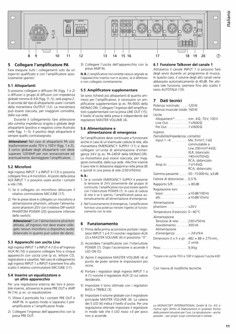
5.1 AltoparlantiSi possono collegare o diffusori PA (figg . 1 e 2) o diffusori o gruppi di diffusori con impedenza globale minima di 4 Ω (figg . 3 – 5), vedi pagina 2 . A seconda del tipo di altoparlante usare i contatti della morsettiera OUTPUT (12) . La morsettiera può essere staccata, per maggiore comodità, dalla sua sede .
Durante il collegamento fare attenzione alla corretta impedenza singola o globale degli altoparlanti (positivo e negativo come illustrato nelle figg . 1 – 5) . Il positivo degli altoparlanti è sempre quello contrassegnato .
Attenzione! Nel caso di altoparlanti PA con trasformatore audio 70 V o 100 V (figg . 1 e 2), il carico globale degli al toparlanti non deve superare 120 Weff per non sovraccaricare ed eventualmente danneggiare l’amplificatore .
5.2 MicrofoniAgli ingressi INPUT 1 a INPUT 4 (13) si possono collegare fino a 4 microfoni . Al posto della presa XLR INPUT 1 si possono usare anche i contatti a vite (18) .
1) Se è collegato un microfono sbloccare il relativo commutatore MIC / LINE (17) .
2) Per le prese dove è collegato un microfono a alimentazione phantom, attivare l’alimenta-zione phantom 20 V con il relativo DIP-switch PHANTOM POWER (20) (posizione inferiore dello switch) .
Attenzione! Con l‘alimentazione phantom attivata, all‘ingresso non deve essere colle-gato nessun microfono o dispositivo audio sbilanciato in quanto può subire dei danni .
5.3 Apparecchi con uscita LineAgli ingressi INPUT 1 a INPUT 4 (13) e all’ingresso AUX IN (16) si possono collegare fino a cinque apparecchi con uscita Line (p . es . lettore CD, registratore a cassette) . Nel caso di collegamento agli ingressi INPUT 1 a INPUT 4 premere fino allo scatto il relativo commutatore MIC / LINE (17) .
5.4 Inserire un equalizzatore o un altro apparecchio
Per una regolazione esterna dei toni è possi-bile inserire, attraverso le prese PRE OUT e AMP IN (14), p . es . un equalizzatore .
1) Sfilare il ponticello fra i contatti PRE OUT e AMP IN . In questo modo si separano il pre-amplificatore e l’amplificatore finale .
2) Collegare l’ingresso dell’apparecchio con la presa PRE OUT .
3) Collegare l’uscita dell’apparecchio con la presa AMP IN .
N. B.: L’amplificatore non emette nessun segnale se l’apparecchio inserito non è acceso, se è difettoso o non collegato correttamente .
5.5 Amplificatore supplementareSe sono richiesti più altoparlanti di quanto am-messi per l’amplificatore, è necessario un am-plificatore supplementare (p . es . PA-900S della MONACOR) . Collegare l’ingresso dell’amplifica-tore supplementare con la presa LINE OUT (15) . Il livello d’uscita della presa è indipendente dal regolatore MASTER VOLUME (4) .
5.6 Alimentazione e alimentazione di emergenza
Se l’amplificatore deve continuare a funzionare anche in caso di un’eventuale caduta di rete, alla morsettiera EMERGENCY SUPPLY (11) si deve collegare un’unità di alimentazione d’emer-genza 24 V (p . es . PA-24ESP della MONACOR) . La morsettiera può essere staccata, per mag-giore comodità, dalla sua sede . Alla fine inserire il cavo rete in dotazione dapprima nella presa (8) e quindi in una presa di rete (230 V/ 50 Hz) .
N. B.: 1 . Se ai contatti EMERGENCY SUPPLY è presente
la tensione di 24 V proveniente dal gruppo di continuità, l’amplificatore non può essere spento con l’interruttore POWER (7) . In caso di caduta di rete e se è spento, l’amplificatore passa au-tomaticamente all’alimentazione d’emergenza
2 . Nel funzionamento d’emergenza, l’amplificatore fornisce una potenza minore rispetto al funzio-namento con la rete .
6 Funzionamento1) Prima della prima accensione portare i rego-
latori INPUT 1 a 4 (1) nonché i regolatori AUX (2) e MASTER VOLUME (4) in posizione “0” .
2) Accendere l’amplificatore con l’interruttore POWER (7) . Dopo l’accensione si accende il LED ON (5) .
3) Aprire il regolatore MASTER VOLUME (4) al punto da poter sentire le impostazioni più vicine .
4) Portare i regolatori degli ingressi INPUT 1 a 4 (1) nonché il regolatore AUX (2) sul valore desiderato .
5) Impostare il tono ottimale con i regolatori BASS e TREBLE (3) .
6) Impostare il volume globale con il regolatore principale MASTER VOLUME (4) . La catena dei 5 LED (6) indica il livello d’uscita . Per una regolazione ottimale impostare il regolatore in modo tale che il LED rosso +3 per poco non si accende .
6.1 Funzione Talkover del canale 1Attraverso il canale INPUT 1 si possono fare degli avvisi durante un programma di musica . In questo caso, il volume degli altri canali viene abbassato automaticamente di 40 dB . Per atti-vare tale funzione, premere fino allo scatto il tasto AUTOTALK (19) .
7 Dati tecniciPotenza nominale: . . . .120 WPotenza musicale totale: 160 W
Dimensioni (l × h × p): .482 × 88 × 275 mm, 2 unità
Peso: . . . . . . . . . . . . . . .9,9 kg
* Usare o le uscite 70 V e 100 V oppure l’uscita 4 Ω!
Con riserva di modifiche tecniche .
La MONACOR ® INTERNATIONAL GmbH & Co. KG si riserva ogni diritto di elaborazione in qualsiasi forma delle presenti istruzioni per l’uso. La riproduzione – anche parziale – per propri scopi commerciali è vietata.
Amplificador Mezclador para MegafoníaLea atentamente estas instrucciones antes del funcionamiento y guárdelas para usos poste-riores .
La conexión de los altavoces (apartado 5 .1) requiere tener conocimientos técnicos adecua-dos de megafonía de 100 V y sólo debe reali-zarse mediante expertos . El funcionamiento del amplificador es sencillo, incluso para adultos sin ningún conocimiento técnico . Sin embargo, si tiene alguna duda, contacte con su instalador o vendedor .
1 Elementos y Conexiones1.1 Parte delantera
1 Controles de nivel de entrada para los ca-nales mono INPUT 1 a INPUT 4
2 Control de nivel de entrada para el canal AUX
3 Ecualizador BASS = control de los graves,
±10 dB /100 HzTREBLE = control de los agudos
±10 dB /10 kHz
4 Control MASTER VOLUME para el volumen total
5 LED on
6 Indicadores del nivel
7 Interruptor ON / OFF
1.2 Parte trasera
8 Jack para conectar con una toma 230 V/ 50 Hz vía el cable de red entregado
9 Soporte para el fusible; solamente reemplace un fusible fundido por uno del mismo tipo
10 Tornillo para posible conexión masa (por ejemplo en caso de problemas de zumbido)
11 Terminales* para alimentador de emergen-cia ( 24 V)
12 Terminales* para conectar los altavoces
13 Jacks de entrada XLR de los canales mono INPUT 1 a INPUT 4 para conectar micrófonos o aparatos con salida línea
¡Precaucion! Cuando se activa la alimen-tación phantom [interruptor DIP corres-pondiente (20) en la posición inferior], los jacks XLR están alimentados por una alimentación phantom de 20 V . En este caso, micrófonos asimétricos o aparatos audio no deben conectarse porque pueden sufrir daños .
14 Jacks PRE OUT y AMP IN para insertar un aparato (por ejemplo ecualizador); el nivel de salida de la toma PRE OUT es inde-pendiente del control MASTER VOLUME (4)
15 Salida LINE OUT para conectar otros ampli-ficadores; el nivel de salida es independiente del con-trol MASTER VOLUME (4)
16 Entrada AUX IN para conectar aparatos audio, por ejemplo lector CD, tuner, cas-sette, etc .
17 Interruptor selector para los canales mono INPUT 1 – 4 entre nivel de micrófono (botón no pulsado) y nivel línea (botón pulsado)
18 Terminales para conectar un micrófono o un aparato audio con salida línea; conectados en paralelo con el jack XLR INPUT 1
19 Botón AUTOTALK para activar/desactivar la función Talkover del canal 1
20 Interruptores DIP +21 V PHANTOM POWER para conectar la alimentación phantom 20 V para los jacks XLR INPUT 1 a INPUT 4 (13); necesarios para conectar micrófonos con-densador o electret que funcionan con una alimentación phantom
¡Precaución! Utilice los interruptores sólo con el amplificador desconectado para evitar el ruido de conexión . Respete los consejos mencionados en el punto nº 13 .
2 Notas de SeguridadEl aparato cumple con todas las directivas rele-vantes de la UE y por lo tanto está marcado con el símbolo .
ADVERTENCIA El aparato utiliza un voltaje pe-ligroso . Deje el mantenimiento para el personal cualificado; el manejo inexperto puede pro-ducir una descarga eléctrica .
Durante el funcionamiento, hay peligro de contacto con un voltaje de hasta 100 V en las conexiones de altavoz (12) . Haga o cambie todas las conexiones sólo con el sistema de megafonía desconectado .
No inserte nunca nada en las rejillas de venti-lación; ¡podría sufrir una descarga eléctrica!
• El aparato está adecuado para utilizarse sólo en interiores . Protéjalo contra goteos, salpi-caduras, humedad elevada y calor (rango de temperatura admisible: 0 – 40 °C) .
• No coloque ningún recipiente lleno de líquido encima del aparato, como por ejemplo un vaso .
• El calor que se genera en el aparato tiene que disiparse mediante la circulación del aire . Por lo tanto, no cubra nunca las rejillas de ventilación .
• No utilice el aparato y desconéctelo inmedia-tamente de la corriente si:1 . El aparato o el cable de corriente están vi-
siblemente dañados .2 . El aparato ha sufrido daños después de una
caída o accidente similar .3 . No funciona correctamente .Sólo el personal técnico puede reparar el apa-rato bajo cualquier circunstancia .
• No tire nunca del cable de red para desco-nectarlo de la toma, tire siempre del enchufe .
• Utilice sólo un paño suave y seco para la lim-pieza; no utilice nunca ni agua ni productos químicos .
• No podrá reclamarse garantía o responsabi-lidad alguna por cualquier daño personal o material resultante si el aparato se utiliza para otros fines diferentes a los originalmente con-cebidos, si no se conecta o no se utiliza ade-cuadamente o si no se repara por expertos .
Si va a poner el aparato definitiva-mente fuera de servicio, llévelo a la planta de reciclaje más cercana para que su eliminción no sea perjudicial para el medioambiente .
3 AplicacionesEl amplificador está especialmente fabricado para una utilización en sistemas de mega- fonía . Pue de entregar 120 W RMS a los altavoces 100 V y 70 V o a un grupo de altavoces con una impedancia total de 4 Ω . Es posible conectar micrófonos (canales 1 – 4) o aparatos con nivel línea (canales 1 – 4 y canal AUX) a los cinco cana-les de entrada mezclables entre ellos . El canal 1 dispone de una función Talkover que disminuye el volumen de los otros canales de 40 dB durante un anuncio .
4 Colocar el AmplificadorEl amplificador está diseñado para una instala-ción en rack (482 mm / 19”), pero también puede colocarse en una mesa . En cualquier caso, el aire debe poder circular libremente a través de las rejillas de ventilación para asegurar un enfria-mento suficiente para el amplificador .
4.1 Instalación en rackPara la instalación en un rack, atornille los dos soportes de montaje entregados hacia los lados del aparato . En el rack, 2 unidades de rack son necesarios para el amplificador (1 unidad rack = 44,5 mm) .
Para prevenir el sobrepeso en la parte supe-rior del rack, inserte el amplificador en la parte inferior del rack . La placa frontal por sí sola no es suficiente para fijarlo con seguridad; utilice también raíles laterales o una placa en la parte inferior para asegurar el aparato .
EspañolEspañol Página
* Es posible sacar los terminales de su conexión para facilitar el manejo .
13
Españ
ol
2 1
3
USE ONLY WITH A 250V FUSE
230 V~ / 50 Hz
+ – GND
GND
24V COM 4Ω 70V 100VL
R
LINE OUT AUX INL
R
PRE OUT
AMP IN
OUTPUT INPUT 4 INPUT 3 INPUT 2 INPUT 1
AUTOTALK
+21 VPHANTOM
POWER
1234
OFFON
OFFON
MICLINE
MICLINE
MICLINE
MICLINE
EMERGENCY SUPPLY
2 1
3
2 1
3
2 1
3
8 9 10 11 12 13 14 15 16 17 18 19 20 ➆
5 Conectar el Amplificador de Megafonía
¡Cualquier conexión debería hacerse por per-sonal autorizado con el amplificador apagado!
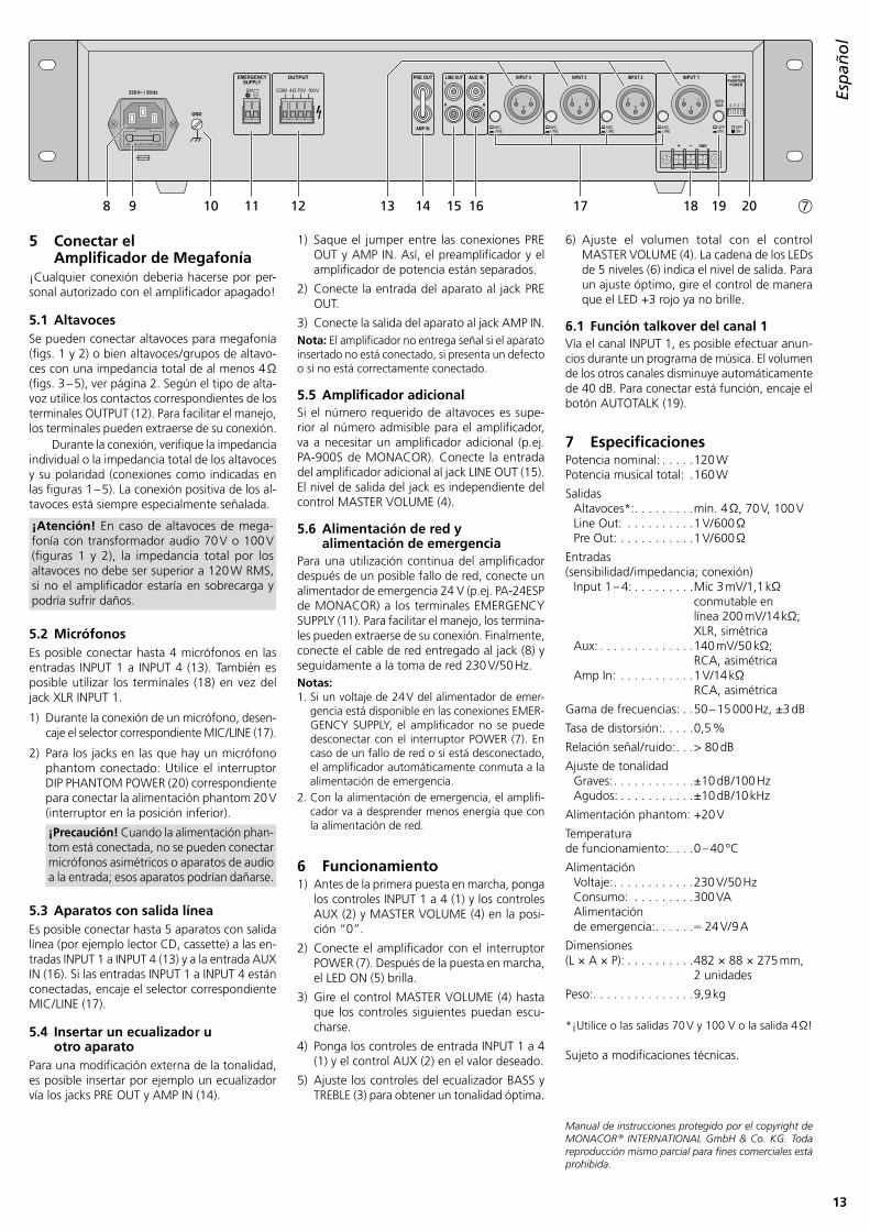
5.1 AltavocesSe pueden conectar altavoces para megafonía (figs . 1 y 2) o bien altavoces / grupos de altavo-ces con una impedancia total de al menos 4 Ω (figs . 3 – 5), ver página 2 . Según el tipo de alta-voz utilice los contactos correspondientes de los terminales OUTPUT (12) . Para facilitar el manejo, los terminales pueden extraerse de su conexión .
Durante la conexión, verifique la impedancia individual o la impedancia total de los altavoces y su polaridad (conexiones como indicadas en las figuras 1 – 5) . La conexión positiva de los al-tavoces está siempre especialmente señalada .
¡Atención! En caso de altavoces de mega- fonía con transformador audio 70 V o 100 V (figuras 1 y 2), la impedancia total por los altavoces no debe ser superior a 120 W RMS, si no el amplificador estaría en sobrecarga y podría sufrir daños .
5.2 MicrófonosEs posible conectar hasta 4 micrófonos en las entradas INPUT 1 a INPUT 4 (13) . También es posible utilizar los terminales (18) en vez del jack XLR INPUT 1 .
1) Durante la conexión de un micrófono, desen-caje el selector correspondiente MIC / LINE (17) .
2) Para los jacks en las que hay un micrófono phantom conectado: Utilice el interruptor DIP PHANTOM POWER (20) correspondiente para conectar la alimentación phantom 20 V (interruptor en la posición inferior) .
¡Precaución! Cuando la alimentación phan-tom está conectada, no se pueden conectar micrófonos asimétricos o aparatos de audio a la entrada; esos aparatos podrían dañarse .
5.3 Aparatos con salida líneaEs posible conectar hasta 5 aparatos con salida línea (por ejemplo lector CD, cassette) a las en-tradas INPUT 1 a INPUT 4 (13) y a la entrada AUX IN (16) . Si las entradas INPUT 1 a INPUT 4 están conectadas, encaje el selector correspondiente MIC / LINE (17) .
5.4 Insertar un ecualizador u otro aparato
Para una modificación externa de la tonalidad, es posible insertar por ejemplo un ecualizador vía los jacks PRE OUT y AMP IN (14) .
1) Saque el jumper entre las conexiones PRE OUT y AMP IN . Así, el preamplificador y el amplificador de potencia están separados .
2) Conecte la entrada del aparato al jack PRE OUT .
3) Conecte la salida del aparato al jack AMP IN .Nota: El amplificador no entrega señal si el aparato insertado no está conectado, si presenta un defecto o si no está correctamente conectado .
5.5 Amplificador adicionalSi el número requerido de altavoces es supe-rior al número admisible para el amplificador, va a necesitar un amplificador adicional (p .ej . PA-900S de MONACOR) . Conecte la entrada del amplificador adicional al jack LINE OUT (15) . El nivel de salida del jack es independiente del control MASTER VOLUME (4) .
5.6 Alimentación de red y alimentación de emergencia
Para una utilización continua del amplificador después de un posible fallo de red, conecte un alimentador de emergencia 24 V (p .ej . PA-24ESP de MONACOR) a los terminales EMERGENCY SUPPLY (11) . Para facilitar el manejo, los termina-les pueden extraerse de su conexión . Finalmente, conecte el cable de red entregado al jack (8) y seguidamente a la toma de red 230 V/ 50 Hz .Notas: 1 . Si un voltaje de 24 V del alimentador de emer-
gencia está disponible en las conexiones EMER-GENCY SUPPLY, el amplificador no se puede desconectar con el interruptor POWER (7) . En caso de un fallo de red o si está desconectado, el amplificador automáticamente conmuta a la alimentación de emergencia .
2 . Con la alimentación de emergencia, el amplifi-cador va a desprender menos energía que con la alimentación de red .
6 Funcionamiento1) Antes de la primera puesta en marcha, ponga
los controles INPUT 1 a 4 (1) y los controles AUX (2) y MASTER VOLUME (4) en la posi-ción “0” .
2) Conecte el amplificador con el interruptor POWER (7) . Después de la puesta en marcha, el LED ON (5) brilla .
3) Gire el control MASTER VOLUME (4) hasta que los controles siguientes puedan escu-charse .
4) Ponga los controles de entrada INPUT 1 a 4 (1) y el control AUX (2) en el valor deseado .
5) Ajuste los controles del ecualizador BASS y TREBLE (3) para obtener un tonalidad óptima .
6) Ajuste el volumen total con el control MASTER VOLUME (4) . La cadena de los LEDs de 5 niveles (6) indica el nivel de salida . Para un ajuste óptimo, gire el control de manera que el LED +3 rojo ya no brille .
6.1 Función talkover del canal 1Vía el canal INPUT 1, es posible efectuar anun-cios durante un programa de música . El volumen de los otros canales disminuye automáticamente de 40 dB . Para conectar está función, encaje el botón AUTOTALK (19) .
* ¡Utilice o las salidas 70 V y 100 V o la salida 4 Ω!
Sujeto a modificaciones técnicas .
Manual de instrucciones protegido por el copyright de MONACOR ® INTERNATIONAL GmbH & Co. KG. Toda reproducción mismo parcial para fines comerciales está prohibida.
Wzmacniacz miksujący PAPrzed rozpoczęciem użytkowania prosimy o zapo-znanie się z instrukcją i zachowanie jej do wglądu .
Podłączanie głośników (rozdz . 5 .1) wymaga wiedzy technicznej na temat systemów PA pracujących w technologii 100 V, i w razie konieczności należy zlecić je specjaliście . Obsługa wzmacniacza jest łatwa nawet dla osób niepo-siadających zaawansowanej wiedzy technicznej . W razie wątpliwości należy skontaktować się z dostawcą lub instalatorem urządzenia .
1 Elementy sterujące i gniazda połączeniowe
1.1 Panel przedni
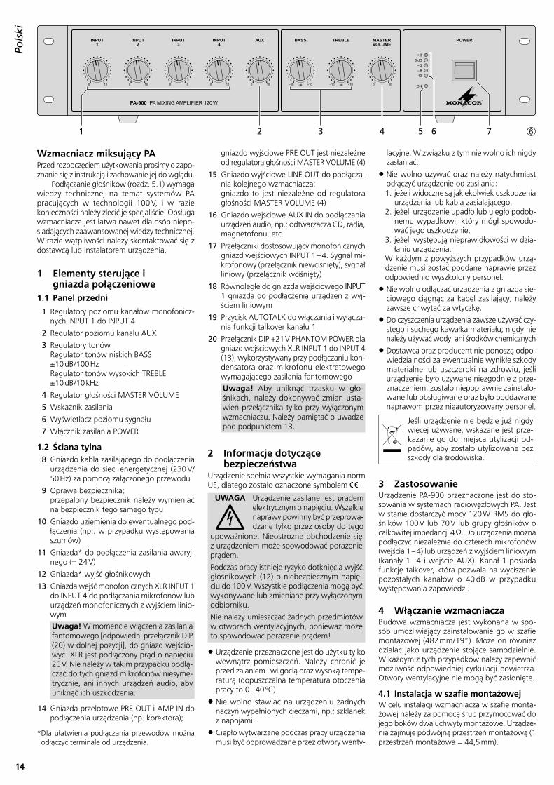
1 Regulatory poziomu kanałów monofonicz-nych INPUT 1 do INPUT 4
2 Regulator poziomu kanału AUX
3 Regulatory tonów Regulator tonów niskich BASS ±10 dB /100 Hz Regulator tonów wysokich TREBLE ±10 dB /10 kHz
4 Regulator głośności MASTER VOLUME
5 Wskaźnik zasilania
6 Wyświetlacz poziomu sygnału
7 Włącznik zasilania POWER
1.2 Ściana tylna8 Gniazdo kabla zasilającego do podłączenia
urządzenia do sieci energetycznej (230 V/ 50 Hz) za pomocą załączonego przewodu
9 Oprawa bezpiecznika; przepalony bezpiecznik należy wymieniać na bezpiecznik tego samego typu
10 Gniazdo uziemienia do ewentualnego pod-łączenia (np .: w przypadku występowania szumów)
11 Gniazda* do podłączenia zasilania awaryj-nego ( 24 V)
12 Gniazda* wyjść głośnikowych
13 Gniazda wejść monofonicznych XLR INPUT 1 do INPUT 4 do podłączania mikrofonów lub urządzeń monofonicznych z wyjściem linio-wym
Uwaga! W momencie włączenia zasilania fantomowego [odpowiedni przełącznik DIP (20) w dolnej pozycji], do gniazd wejścio-wyc XLR jest podłączony prąd o napięciu 20 V . Nie należy w takim przypadku podłą-czać do tych gniazd mikrofonów niesyme-trycznie, ani innych urządzeń audio, aby uniknąć ich uszkodzenia .
14 Gniazda przelotowe PRE OUT i AMP IN do podłączenia urządzenia (np . korektora);
gniazdo wyjściowe PRE OUT jest niezależne od regulatora głośności MASTER VOLUME (4)
15 Gniazdo wyjściowe LINE OUT do podłącza-nia kolejnego wzmacniacza; gniazdo to jest niezależne od regulatora głośności MASTER VOLUME (4)
16 Gniazdo wejściowe AUX IN do podłączania urządzeń audio, np .: odtwarzacza CD, radia, magnetofonu, etc .
18 Równoległe do gniazda wejściowego INPUT 1 gniazda do podłączenia urządzeń z wyj-ściem liniowym
19 Przycisk AUTOTALK do włączania i wyłącza-nia funkcji talkover kanału 1
20 Przełącznik DIP +21 V PHANTOM POWER dla gniazd wejściowych XLR INPUT 1 do INPUT 4 (13); wykorzystywany przy podłączaniu kon-densatora oraz mikrofonu elektretowego wy magającego zasilania fantomowego
Uwaga! Aby uniknąć trzasku w gło-śnikach, należy dokonywać zmian usta-wień przełącznika tylko przy wyłączonym wzmacniaczu . Należy pamiętać o uwadze pod podpunktem 13 .
2 Informacje dotyczące bezpieczeństwa
Urządzenie spełnia wszystkie wymagania norm UE, dlatego zostało oznaczone symbolem .
UWAGA Urządzenie zasilane jest prądem elektrycznym o napięciu . Wszelkie naprawy powinny być przeprowa-dzane tylko przez osoby do tego
upoważnione . Nieostrożne obchodzenie się z urządzeniem może spowodować porażenie prądem .
Podczas pracy istnieje ryzyko dotknięcia wyjść głośnikowych (12) o niebezpiecznym napię-ciu do 100 V . Wszystkie podłączenia mogą być wykonywane lub zmieniane przy wyłączonym odbiorniku .
Nie należy umieszczać żadnych przedmiotów w otworach wentylacyjnych, ponieważ może to spowodować porażenie prądem!
• Urządzenie przeznaczone jest do użytku tylko wewnątrz pomieszczeń . Należy chronić je przed zalaniem i wilgocią oraz wysoką tempe-raturą (dopuszczalna temperatura otoczenia pracy to 0 – 40 ºC) .
• Nie wolno stawiać na urządzeniu żadnych naczyń wypełnionych cieczami, np .: szklanek z napojami .
• Ciepło wytwarzane podczas pracy urządzenia musi być odprowadzane przez otwory wenty-
lacyjne . W związku z tym nie wolno ich nigdy zasłaniać .
• Nie wolno używać oraz należy natychmiast odłączyć urządzenie od zasilania:1 . jeżeli widoczne są jakiekolwiek uszkodzenia
urządzenia lub kabla zasialającego,2 . jeżeli urządzenie upadło lub uległo podob-
nemu wypadkowi, który mógł spowodo-wać jego uszkodzenie,
3 . jeżeli występują nieprawidłowości w dzia-łaniu urządzenia .
W każdym z powyższych przypadków urzą-dzenie musi zostać poddane naprawie przez odpowiednio wyszkolony personel .
• Nie wolno odłączać urządzenia z gniazda sie-ciowego ciągnąc za kabel zasilający, należy zawsze chwytać za wtyczkę .
• Do czyszczenia urządzenia zawsze używać czy-stego i suchego kawałka materiału; nigdy nie należy używać wody, ani środków chemicznych
• Dostawca oraz producent nie ponoszą odpo-wiedzialności za ewentualnie wynikłe szkody materialne lub uszczerbki na zdrowiu, jeśli urządzenie było używane niezgodnie z prze-znaczeniem, zo stało niepoprawnie zainstalo-wane lub obsługiwane oraz było poddawane naprawom przez nieautoryzowany personel .
Jeśli urządzenie nie będzie już nigdy więcej używane, wskazane jest prze-kazanie go do miejsca utylizacji od-padów, aby zostało utylizowane bez szkody dla środowiska .
3 ZastosowanieUrządzenie PA-900 przeznaczone jest do sto-sowania w systemach radiowęzłowych PA . Jest w stanie dostarczyć mocy 120 W RMS do gło-śników 100 V lub 70 V lub grupy głośników o całkowitej impedancji 4 Ω . Do urządzenia można podłączyć niezależnie do czterech mikrofonów (wejścia 1 – 4) lub urządzeń z wyjściem liniowym (kanały 1 – 4 i wejście AUX) . Kanał 1 posiada funkcję talkover, która pozwala na wyciszenie pozostałych kanałów o 40 dB w przypadku występowania zapowiedzi .
4 Włączanie wzmacniaczaBudowa wzmacniacza jest wykonana w spo-sób umożliwiający zainstalowanie go w szafie montażowej (482 mm / 19”) . Może on również działać jako urządzenie stojące samodzielnie . W każdym z tych przypadków należy zapewnić możliwość odpowiedniej cyrkulacji powietrza . Otwory wentylacyjne nie mogą być zasłonięte .
4.1 Instalacja w szafie montażowejW celu instalacji wzmacniacza w szafie monta-żowej należy za pomocą śrub przymocować do jego boków dwa uchwyty montażowe . Urządze-nia zajmuje podwójną przestrzeń montażową (1 przestrzeń montażowa = 44,5 mm) .
PolskiPolski Strona
* Dla ułatwienia podłączania przewodów można odłączyć terminale od urządzenia .
15
Polski
2 1
3
USE ONLY WITH A 250V FUSE
230 V~ / 50 Hz
+ – GND
GND
24V COM 4Ω 70V 100VL
R
LINE OUT AUX INL
R
PRE OUT
AMP IN
OUTPUT INPUT 4 INPUT 3 INPUT 2 INPUT 1
AUTOTALK
+21 VPHANTOM
POWER
1234
OFFON
OFFON
MICLINE
MICLINE
MICLINE
MICLINE
EMERGENCY SUPPLY
2 1
3
2 1
3
2 1
3
8 9 10 11 12 13 14 15 16 17 18 19 20 ➆
W celu uniknięcia przeciążenia górnej czę-ści szafy montażowej wzmacniacz powinien być instalowany w dolnej jej części . Instalacja wzmac-niacza jedynie za pomocą zamocowanych w przedniej części uchwytów montażowych nie jest wystarczająca . Należy użyć dodatkowo bocznych szyn podtrzymujących bądź płyty montażowej .
5 Podłączanie wzmacniacza PAWszelkie podłączenia mogą być wykonywane jedynie przez wyszkolony personel i zawsze przy wyłączonym wzmacniaczu!
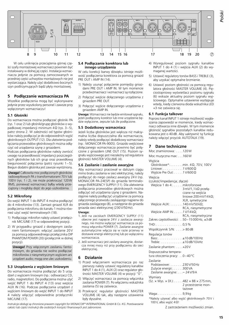
5.1 GłośnikiDo wzmacniacza można podłączać głośniki PA (rys . 1 oraz 2) lub głośnik/grupę głośników o wy-padkowej impedancji minimum 4 Ω (rys . 3 – 5), patrz strona 2 . W zależności od typów głośni-ków należy podłączyć je do odpowiednich wyjść głośnikowych OUTPUT (12) . Dla ułatwienia pod-łączania przewodów głośnikowych można odłą-czyć od urządzenia szynę z gniazdemi .Podczas podłączania głośników należy zwrócić uwagę na prawidłowość impedancji poszczegól-nych głośników lub ich grup oraz prawidłową biegunowość połączenia (patrz rysunki 1 – 5) . Biegun dodatni głośnika jest zawsze wyróżniony .
Uwaga! Całkowita moc podłączonych głośników radio węzłowych PA z transformatorami 70 V lub 100 V (rys . 1 i 2), nie może przekroczyć 120 W RMS, ponieważ wzmacniacz byłby wtedy prze-ciążony i mogłoby dojść do jego uszkodzenia .
5.2 MikrofonyDo wejść INPUT 1 do INPUT 4 można podłączyć do 4 mikrofonów (13) . Zamiast gniazd XLR do podłączenia mikrofonu do kanału 1 można rów-nież użyć wejść terminalowych (18) .
1) Podłączając mikrofon należy ustawić przełącz-nik MIC / LINE (17) w odpowiedniej pozycji .
2) W przypadku gniazd z dostępnym zasila-niem fantomowym: włączyć zasilanie 20 V za pomocą odpowiedniego przełącznika DIP PHANTOM POWER (20) (przełącznik w dolnej pozycji) .
Uwaga! Przy włączonym zasilaniu fanto-mowym, do gniazda nie wolno podłączać mikrofonów z niesymetrycznym wyjściem ani urządzeń audio; mogą one ulec uszkodzeniu .
5.3 Urządzenia z wyjściem liniowymDo wzmacniacza można podłączyć do 5 urzą-dzeń z wyjściem liniowym (np .: odtwarzacz CD, radio, magnetofon) . Do podłączenia można użyć wejść INPUT 1 do INPUT 4 (13) oraz wejścia AUX IN (16) . Podczas podłączania urządzeń z wyjściem liniowym do wejść INPUT 1 do INPUT 4 należy włączyć odpowiednie przełączniki MIC / LINE (17) .
5.4 Podłączanie korektora lub innego urządzenia
W celu korekcji barwy dźwięku istnieje możli-wość podłączenia korektora za pomocą gniazd PRE OUT i AMP IN (14) .
1) Należy usunąć połączenie pomiędzy gniaz-dami PRE OUT i AMP IN . W tym momencie przedwzmacniacz i wzmacniacz są rozłączone .
2) Połączyć wejście dołączanego urządzenia z gniazdem PRE OUT .
3) Połączyć wyjście dołączanego urządzenia z gniazdem AMP IN .
Uwaga: Wzmacniacz nie będzie emitował sygnału, jeżeli podłączony korektor lub inne urządzenie bę-dzie wyłączone, zepsute lub źle podłączone .
5.5 Dodatkowy wzmacniaczJeżeli liczba głośników jest większa niż maksy-malna liczba dopuszczalna dla wzmacniacza, należy wtedy podłączyć dodatkowy wzmacniacz (np .: MONACOR PA-900S) . Gniazdo wejściowe dołączanego wzmacniacza powinno być połą-czone z gniazdem LINE OUT (15) . Poziom sy-gnału wyjściowego jest niezależny od regulatora głośności MASTER VOLUME (4) .
5.6 Zasilanie i zasilanie awaryjneAby wzmacniacz pracował w dalszym ciągu mimo braku zasilania w sieci elektrycznej, należy pod łączyć do niego zasilacz awaryjny 24 V (np . MONACOR PA-24ESP) do gniazda terminalo-wego EMERGENCY SUPPLY (11) . Dla ułatwienia podłączania przewodów głośnikowych można odłączyć od urządzenia szynę z gniazdemi . Na-stępnie należy podłączyć urządzenie za pomocą załączonego przewodu zasilającego najpierw do gniazda zasilającego (8), a następnie do gniazda gniazda sieci elektrycznej (230 V/ 50 Hz) .Uwaga: 1 . Jeśli na zaciskach EMERGENCY SUPPLY (11)
obecne jest napięcie 24 V z zasilacza awaryj-nego, nie można wyłączyć wzmacniacza za po-mocą włącznika POWER (7) . Zasilanie awaryjne automatycznie włącza się w razie przerwy w dostawie energii elektrycznej lub po wyłączeniu wzmacniacza .
2 . Jeśli wzmacniacz jest zasilany awaryjnie, dostar-cza mniej mocy niż przy podłączeniu do sieci elektrycznej .
6 Działanie1) Przed włączeniem wzmacniacza po raz
pierwszy należy ustawić regulatory kanałów INPUT 1 do 4 (1), AUX (2) oraz regulator gło-śności MASTER VOLUME (4) w pozycji “0” .
2) Włączyć wzmacniacz za pomocą włącznika zasilania POWER (7) . Po włączeniu wskaźnika zasilania (5) się zaświeca .
3) Przekręcić regulator głośności MASTER VO LUME (4) tak, aby następne ustawienia były słyszalne .
4) Wyregulować poziom sygnału kanałów INPUT 1 do 4 (1) i wejścia AUX (2) do wy-maganej wartości .
5) Ustawić regulatory tonów BASS i TREBLE (3), aby uzyskać optymalne brzmienie .
6) Ustawić poziom głośności za pomocą regu-latora głośności MASTER VOLUME (4) . Pię-ciostopniowy wyświetlacz poziomu sygnału (6) wskaże aktualny poziom sygnału wyj-ściowego . Optymalne ustawienie występuje wtedy, kiedy czerwona dioda wskaźnika LED +3 nie zaświeca się .
6.1 Funkcja talkoverPoprzez kanał INPUT 1 istnieje możliwość wygła-szania zapowiedzi w momencie, kiedy wzmac-niacz odtwarza inne dźwięki . W tym momencie głośność sygnałów pozostałych kanałów redu-kowana jest o 40 dB . Aby uaktywnić tą funkcję należy włączyć przycisk AUTOTALK (19) .
Waga: . . . . . . . . . . . . . .9,9 kg* Należy używać albo wyjść głośnikowych 70 V i 100 V, albo wyjść 4 Ω!
Z zastrzeżeniem możliwości zmian .Instrukcje obsługi są chronione prawem copyright for MONACOR ® INTERNATIONAL GmbH & Co. KG. Przetwarzanie całości lub części instrukcji dla osobistych korzyści finansowych jest zabronione.
16
Ned
erlands
EspañolEspañol Página
PolskiPolski Strona
SvenskaSvenska Sidan
Dan
sk
DanskDansk Sida
NederlandsNederlands Pagina
Alle rettigheder til denne brugsvejledning tilhører MONACOR ® INTERNATIONAL GmbH & Co. KG. Ingen dele af denne vejledning må reproduceres under ingen omstændigheder til kommerciel anvendelse.
Læs nedenstående sikkerhedsoplysninger op-mærksomt igennem før ibrugtagning af enhe-den . Bortset fra sikkerhedsoplysningerne henvi-ses til den engelske tekst .
Vigtige sikkerhedsoplysninger
Denne enhed overholder alle relevante EU- direktiver, og er derfor mærket med .
ADVARSEL Enheden benytter livsfarlig net-spænd ing . For at undgå fare for elektrisk stød må kabinettet ikke åbnes . Overlad servicering til autoriseret personel .
Under drift er der farlig spænding op til 100 V på højtaler terminalerne (12) . Husk altid at slukke for PA-anlægget før til slutning eller en hvilken som helst ændring af tilslutningerne .
Undlad at indføre noget i ventilationshullerne! Dette kan forårsage fare for elektrisk stød .
• Enheden er kun beregnet til indendørs brug . Be skyt den mod vanddråber og -stænk, høj luft fug tig hed og varme (tilladt omgivelses tem-pera tur 0 – 40 °C) .
• Undgå at placere væskefyldte genstande, som f . eks . glas, ovenpå enheden .
• Varmen, der udvikles i enheden, skal kunne slippe ud ved hjælp af luftcirku lation . Enhe-dens ventila tionshuller må derfor aldrig til-dækkes .
• Tag ikke enheden i brug og tag straks stikket ud af stikkontakten i følgende tilfælde:1 . hvis der er synlig skade på enheden eller
net kablet,2 . hvis der kan være opstået skade, efter at
en heden er tabt eller lignende,3 . hvis der forekommer fejlfunktion .Enheden skal altid repareres af autoriseret per sonel .
• Tag aldrig stikket ud af stikkontakten ved at trække i kablet, tag fat i selve stikket .
• Til rengøring må kun benyttes en tør, blød klud; der må under ingen omstændigheder benyttes ke mikalier eller vand .
• Hvis enheden benyttes til andre formål, end den oprindeligt er beregnet til, hvis den ikke er korrekt tilsluttet, hvis den betjenes forkert,
eller hvis den ikke repareres af autoriseret personel, omfattes eventuelle skader ikke af garantien .
Hvis enheden skal tages ud af drift for bestandigt, skal den bringes til en lokal genbrugsstation for bortskaffelse .
Deze gebruiksaanwijzing is door de auteurswet beschermd eigendom van MONACOR ® INTERNATIONAL GmbH & Co. KG. Een reproductie – ook gedeeltelijk – voor eigen commerciële doeleinden is verboden.
Lees aandachtig de onderstaande veiligheidsvoor-schriften, alvorens het toestel in gebruik te ne men . Mocht u bijkomende informatie over de bediening van het toestel nodig hebben, lees dan de En gelse tekst van deze handleiding .
VeiligheidsvoorschriftenHet apparaat is in overeenstemming met alle relevante EU-Richtlijnen en is daarom geken-merkt met .
WAARSCHUWING De netspanning van het toestel is levensgevaar-lijk . Open het toestel niet, want door on zorgvuldige
ingrepen loopt u het risico van elektrische schokken .
Tijdens het gebruik staan de luidspre ker aan-sluitingen (12) onder een le vens gevaarlijke spanning tot 100 V . De in- en uitgangen mogen enkel aangesloten en gewijzigd worden, wan-neer de 100 V-versterker is uitgeschakeld .
Zorg ervoor dat u niets in de ventilatieope-ningen steekt . Er bestaat immers gevaar voor elektrische schokken! .
• Het toestel is enkel geschikt voor gebruik bin-nenshuis . Vermijd druip- en spatwater, uitzon-derlijk warme plaatsen en plaatsen met een hoge vochtigheid (toegestaan omgevingstem-peratuurbereik: 0 – 40 °C) .
• Plaats geen bekers met vloeistof zoals drink-glazen etc . op het toestel .
• De warmte die in het toestel ontstaat, moet door ventilatie afgevoerd worden . Dek de ventilatieopeningen niet af .
• Schakel het toestel niet in resp . trek onmid-dellijk de stekker uit het stopcontact:
1 . wanneer het toestel of het netsnoer zicht-baar beschadigd zijn,
2 . wanneer er een defect zou kunnen optre-den nadat het toestel bijvoorbeeld gevallen is,
3 . wanneer het toestel slecht functioneert .
Het apparaat moet in elk geval hersteld wor-den door een gekwalificeerd vakman .
• Trek de stekker nooit met het snoer uit het stopcontact, maar met de stekker zelf .
• Verwijder het stof enkel met een droge doek . Gebruik zeker geen chemicaliën of water .
• In geval van ongeoorloofd of verkeerd ge-bruik, verkeerde aansluiting resp . bediening of van herstelling door een niet-gekwalificeerd persoon vervalt de garantie en de verantwoor-delijkheid voor hieruit resulterende materiële of lichamelijke schade .
Wanneer het toestel definitief uit be-drijf genomen wordt, bezorg het dan voor milieuvriendelijke verwerking aan een plaatselijk recyclagebedrijf .
17
Sven
ska
Suomi
SvenskaSvenska Sidan
SuomiSuomi Sivulta
Kaikki oikeudet pidätetään MONACOR ® INTERNATIONAL GmbH & Co. KG. Mitään tämän käyttöohjeen osaa ei saa jäljentää miltään osin käytettäväksi mihinkään kaupallisiin tarkoituksiin.
Tämä laite täyttää kaikki siihen kohdistuvat EU-direktiivit ja sille on myönnetty hyväk-syntä .
VAROITUS Tämä laite toimii hengenvaaral-lisella jännitteellä . Välttääksesi sähköiskun, älä avaa laitteen koteloa . Jätä huoltotoimet val-tuutetulle, am mat titaitoiselle huoltoliikkeelle .
Käytön aikana kaiutinterminaaleissa (12) on vaa rallinen jopa 100 V jännite . Sammuta aina PA-lait teisto kaikkien kytkentöjen suorittamisen ajaksi .
Älä työnnä mitään esinettä tuuletusaukosta sisään! Sähköiskun vaara .
• Tämä laite soveltuu vain sisätilakäyttöön . Suo-jele lai tetta kosteudelta, vedeltä ja kuumuu-delta (sallittu ympä röivä lämpötila 0 – 40 °C) .
• Älä sijoita laitteen päälle mitään nestettä si-sältävää, kuten vesilasia tms .
• Laitteessa kehittyvä lämpö poistetaan il man-vaih dolla . Tämän vuoksi laitteen tuuletusauk-koja ei saa peittää .
• Irrota virtajohto pistorasiasta, äläkä käynnistä laitetta jos:1 . laitteessa tai virtajohdossa on havaittava
vaurio2 . putoaminen tai muu vastaava vahinko on
saattanut aiheuttaa vaurion3 . laitteessa esiintyy toimintahäiriöitäKaikissa näissä tapauksissa laite tulee toimittaa valtuutettuun huoltoliikkeeseen .
• Älä koskaan irrota virtajohtoa pistorasias ta johdosta vetämällä .
• Käytä puhdistamiseen pelkästään kuivaa, pehmeää kangasta . Älä käytä kemikaaleja tai vettä .
• Laitteen takuu raukeaa, eikä valmistaja, maahantuoja tai myyjä ota vastuuta mahdol-lisista välit tömistä tai välillisistä vahingoista, jos laitetta on käytetty muuhun kuin alku-
peräiseen käyttötarkoitukseen, laitet ta on taitamattomasti käytetty tai kytketty tai jos laitetta on huollettu muussa kuin valtuute-tussa huollossa .
Kun laite poistetaan lopullisesti käy-töstä, vie se paikalliseen kierrätyskes-kukseen jälkikäsittelyä varten .
Ole hyvä ja huomioi joka tapauksessa seuraa-vat turvallisuuteen liittyvät seikat ennen laitteen käyttöä . Laitteen toiminnasta saa lisätietoa tar-vittaessa tämän laitteen muunkielisistä käyttö-ohjeista .
Turvallisuudesta
Alla rättigheter är reserverade av MONACOR ® INTERNATIONAL GmbH & Co. KG. Ingen del av denna instruktionsmanual får eftertryckas i någon form eller på något sätt användas i kommersiellt syfte.
Ge akt på säkerhetsinformationen innan enhe-ten tas i bruk . Skulle ytterliggare information behövas kan den återfinnas i manualen för andra språk .
SäkerhetsföreskrifterEnheten uppfyller relevanta Eu-direktiv och har därför försetts med symbolen .
VARNING Enheten använder högspän-ning in ternt . För att undvika elskador, öppna aldrig chassiet på egen hand utan överlåt all
service till auktoriserad verkstad .
Vid drift så finns det mycket farliga spänningar, upp till 100 V förekommer på högtalartermi-nalerna (12) . Stäng alltid av PA systemet innan man gör några inkopplings förändringar .
Stoppa inte in något i ventilations hållen! Risk for elchock .
• Enheten är endast avsedd för inomhusbruk . Skyd da enheten mot vätskor, hög luftfuktig-het och hög värme (tillåten omgivningstem-peratur 0 – 40 °C) .
• Placera inte föremål innehållande vätskor, t . ex . drick sglas, på enheten .
• Värmen som alstras vid användning leds bort genom självcirkulering . Täck därför aldrig över enheten eller ställ den så att luftcirkuleringen försämras .
• Använd inte enheten och tag omedelbart ut kontakten ur eluttaget om något av följande uppstår:1 . Enheten eller elsladden har synliga skador .2 . Enheten är skadad av fall ed .3 . Enheten har andra felfunktioner .Enheten skall lämnas till auktoriserad verkstad för service .
• Dra aldrig ut kontakten genom att dra i slad-den utan ta tag i kontaktkroppen .
• Rengör endast med en mjuk och torr trasa, an vänd aldrig kemikalier eller vatten vid ren-göring .
• Om enheten används på annat sätt än som avses, om den inte kopplas in ordentligt, om den används på fel sätt eller inte repareras av auktoriserad per sonal upphör alla garan-tier att gäll . I dessa fall tas inget ansvar för uppkommen skada på person eller materiel .
Om enheten ska tas ur drift slutgiltigt, ta den till en lokal återvinningsanlägg-ning för en avyttring som inte är skad-ligt för miljön .