LETTERSPUBLISHED ONLINE: 4 JULY 2016 | DOI: 10.1038/NPHYS3808
Elastic instability-mediated actuation by asupra-molecular polymerAviad Levin1,2†, Thomas C. T. Michaels2†, Lihi Adler-Abramovich3, Thomas O. Mason2,Thomas Müller2,4, Bohan Zhang2, L. Mahadevan5,6, Ehud Gazit1,7* and Tuomas P. J. Knowles2*In nature, fast, high-power-density actuation can be achievedthrough the release of stored elastic energy by exploitingmechanical instabilities in systems including the closure of theVenus flytrap1 and the dispersal of plant or fungal spores2.Here, we use droplet microfluidics to tailor the geometry of ananoscale self-assembling supra-molecular polymer to createa mechanical instability. We show that this strategy allowsthe build-up of elastic energy as a result of peptide self-assembly, and its releasewithinmillisecondswhen the buckledgeometry of the nanotube confined within microdropletsbecomes unstable with respect to the straight form. Theseresults overcome the inherent limitations of self-assembly forgenerating large-scale actuation on the sub-second timescaleand illuminate the possibilities and performance limits ofirreversible actuation by supra-molecular polymers.
Self-assembly is a ubiquitous phenomenon in nature thatunderlies the formation of the nanoscale machinery of life,including protein filaments3,4, molecularmotors5 and other complexarchitectures. This process involves the molecular recognitionand association of building blocks mediated by non-covalentinteractions, ultimately leading to supra-molecular species withunique characteristics, such as the ability to assemble reversibly, tomodulate structure stiffness and to respond to external stimuli6–8. Inbiological systems, it has long been revealed that cellular movementand traction at surfaces is controlled by the self-assembly ofcytoskeletal proteins4,9–17.
The self-assembly of biomimetic building blocks is also anattractive route towards force generation in an artificial setting dueto the fact that such processes take place under ambient conditions,with no, or minimal, requirements for external energy input.However, due to the highly dynamical nature of molecular-levelself-assembly phenomena, it has been challenging to achieve rapidmovement on length scales exceeding that of the building blocksthemselves. A strategy to overcome these limitations is to decouplethe slow build-up of potential energy, typically in the form of elasticenergy, from its rapid release by exploiting mechanical instabilities.Natural systems use mechanical instabilities to generate remarkablyrapid movements, including the closure of the Venus flytrap1 orthe dispersal of spores and seeds by plants, fungi or bacteria2,18, butits coupling to self-assembly has not been reported. Here we focuson the dynamics of a dipeptide system, namely the self-assemblyof diphenylalanine (FF) into nanostructures19–23. By confiningthe growing nanostructures inside microdroplets and presenting
real-time imaging, we show that the self-assembly process can resultin the build-up of elastic energy from the buckling and bending ofthe nanostructures.
To probe the force generated by the growth of self-assembled FFtubes, we used a microdroplet platform. FF was initially solubilizedin acetic acid to form a stock solution of 100–300mgml−1 thatwas flowed directly into the microfluidic device; in a first junctionon the device, this stock solution was diluted in equal part withwater, yielding a super-saturated solution of 50–150mgml−1 FF.Immediately aftermixing, this solutionwas compartmentalized intomicrodroplets at the secondT-junction on-chip into a fluorinated oilphase. Droplets were subsequently collected and stored off-chip.
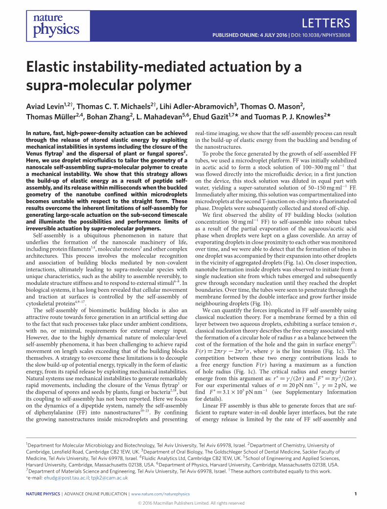
We first observed the ability of FF building blocks (solutionconcentration 50mgml−1 FF) to self-assemble into robust tubesas a result of the partial evaporation of the aqueous/acetic acidphase when droplets were kept on a glass coverslide. An array ofevaporating droplets in close proximity to each other wasmonitoredover time, and we were able to detect that the formation of tubes inone droplet was accompanied by their expansion into other dropletsin the vicinity of aggregated droplets (Fig. 1a). On closer inspection,nanotube formation inside droplets was observed to initiate from asingle nucleation site from which tubes emerged and subsequentlygrew through secondary nucleation until they reached the dropletboundaries. Over time, the tubes were seen to penetrate through themembrane formed by the double interface and grow further insideneighbouring droplets (Fig. 1b).
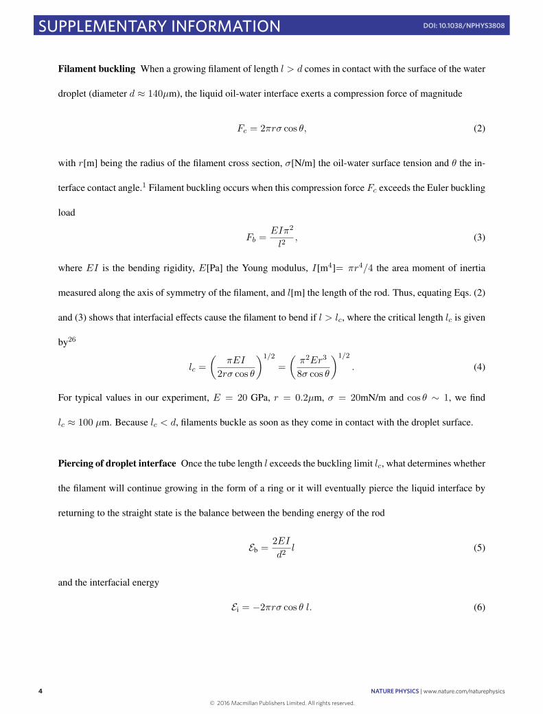
We can quantify the forces implicated in FF self-assembly usingclassical nucleation theory. For a membrane formed by a thin oillayer between two aqueous droplets, exhibiting a surface tension σ ,classical nucleation theory describes the free energy associated withthe formation of a circular hole of radius r as a balance between thecost of the formation of the hole and the gain in surface energy25:F(r)= 2πrγ − 2πr 2σ , where γ is the line tension (Fig. 1c). Thecompetition between these two energy contributions leads toa free energy function F(r) having a maximum as a functionof hole radius (Fig. 1c). The critical radius and energy barrieremerge from this argument as: r∗= γ /(2σ) and F∗= πγ 2/(2σ).For our experimental values of σ = 20 pNnm−1, γ = 2 pN, wefind F∗=3.1×10⁵ pNnm−1 (see Supplementary Informationfor details).
Linear FF assembly is thus able to generate forces that are suf-ficient to rupture water-in-oil double layer interfaces, but the rateof energy release is limited by the rate of FF self-assembly and
1Department for Molecular Microbiology and Biotechnology, Tel Aviv University, Tel Aviv 69978, Israel. 2Department of Chemistry, University ofCambridge, Lensfield Road, Cambridge CB2 1EW, UK. 3Department of Oral Biology, The Goldschleger School of Dental Medicine, Sackler Faculty ofMedicine, Tel Aviv University, Tel Aviv 69978, Israel. 4Fluidic Analytics Ltd, Cambridge CB2 1EW, UK. 5School of Engineering and Applied Sciences,Harvard University, Cambridge, Massachusetts 02138, USA. 6Department of Physics, Harvard University, Cambridge, Massachusetts 02138, USA.7Department of Materials Science and Engineering, Tel Aviv University, Tel Aviv 69978, Israel. †These authors contributed equally to this work.*e-mail: [email protected]; [email protected]
NATURE PHYSICS | ADVANCE ONLINE PUBLICATION | www.nature.com/naturephysics 1
© 2016 Macmillan Publishers Limited. All rights reserved
LETTERS NATURE PHYSICS DOI: 10.1038/NPHYS3808
hr
Oil
Water
Oil
Water
Monomer
Oil phase
Fibril
Secondarynucleation
Nucleation
Oil phase Oil phase
Piercingand fibrilproliferationGrowth
b
c
0 s 11 s 40 s 86 s
a
Line tension
Free
ene
rgy
F∗
Surfacetension
r
10 μm
Figure 1 | FF tubes are able to pierce through water-in-oil double layer interfaces. a, Bright-field time-lapse microscopy of supercritical FF-containingdroplets. Tube formation occurs during incubation through primary and secondary24 nucleation processes. At a later stage, the tubes can be seen to piercethrough the droplet interface, allowing the propagation of tube nucleation in surrounding droplets. b, Schematic representation of the nucleation, growthand piercing of the FF tubes within the aqueous droplets surrounded by the inert oil phase. c, Schematic representation of the tube piercing the oil interfacebetween adjacent droplets (top) and components involved in the calculation of the force generation (bottom).
10 µm
5 µm
1 µm
1 µm
10 12 14 16 18
Unbuckling
Stablestorage
0.01
0.02
0.03
0.04
1
Lineargrowth
Instability
region
Dropletevaporation
Fibrilthickening1
20 µm
Time (s)l/d
Oil phase Oil phase
Elasticinstabilityd < dcr > rc
Oil phase
Axial andlateral
nanotubegrowth
Bucklingl > lc, d
Dropletevaporation
Axial andlateralgrowth
d
ca
rd−2
/3 (µ
m1/
3 )
l/l c
b
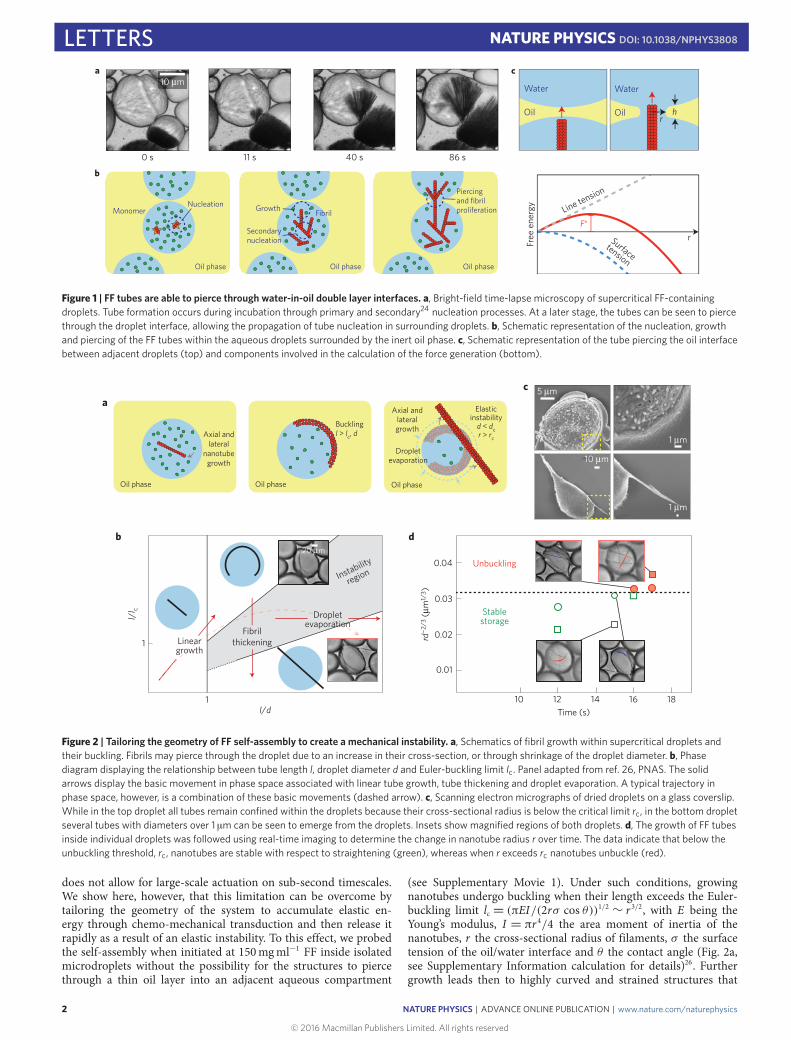
Figure 2 | Tailoring the geometry of FF self-assembly to create a mechanical instability. a, Schematics of fibril growth within supercritical droplets andtheir buckling. Fibrils may pierce through the droplet due to an increase in their cross-section, or through shrinkage of the droplet diameter. b, Phasediagram displaying the relationship between tube length l, droplet diameter d and Euler-buckling limit lc. Panel adapted from ref. 26, PNAS. The solidarrows display the basic movement in phase space associated with linear tube growth, tube thickening and droplet evaporation. A typical trajectory inphase space, however, is a combination of these basic movements (dashed arrow). c, Scanning electron micrographs of dried droplets on a glass coverslip.While in the top droplet all tubes remain confined within the droplets because their cross-sectional radius is below the critical limit rc, in the bottom dropletseveral tubes with diameters over 1 µm can be seen to emerge from the droplets. Insets show magnified regions of both droplets. d, The growth of FF tubesinside individual droplets was followed using real-time imaging to determine the change in nanotube radius r over time. The data indicate that below theunbuckling threshold, rc, nanotubes are stable with respect to straightening (green), whereas when r exceeds rc nanotubes unbuckle (red).
does not allow for large-scale actuation on sub-second timescales.We show here, however, that this limitation can be overcome bytailoring the geometry of the system to accumulate elastic en-ergy through chemo-mechanical transduction and then release itrapidly as a result of an elastic instability. To this effect, we probedthe self-assembly when initiated at 150mgml−1 FF inside isolatedmicrodroplets without the possibility for the structures to piercethrough a thin oil layer into an adjacent aqueous compartment
(see Supplementary Movie 1). Under such conditions, growingnanotubes undergo buckling when their length exceeds the Euler-buckling limit lc = (πEI/(2rσ cos θ))1/2 ∼ r 3/2, with E being theYoung’s modulus, I = πr 4/4 the area moment of inertia of thenanotubes, r the cross-sectional radius of filaments, σ the surfacetension of the oil/water interface and θ the contact angle (Fig. 2a,see Supplementary Information calculation for details)26. Furthergrowth leads then to highly curved and strained structures that
2
© 2016 Macmillan Publishers Limited. All rights reserved
NATURE PHYSICS | ADVANCE ONLINE PUBLICATION | www.nature.com/naturephysics
NATURE PHYSICS DOI: 10.1038/NPHYS3808 LETTERS
NaClO4
NaClO4
Unbuckling
Osmosis
FC-40
FC-40
PDMS membrane
Sample channel
Osmolyte channel
Stable storage Chemical actuation
0 s 10 s 20 s 30 s
H20CH3COOH
PDMS membrane PDMS membrane
PDMS membraneActivation ofosmotic mass
transport
b
20 μm
Unbuckling
R Δx
Δx
E
c
a
Samplechannel
Osmolytechannel
Sampleinlet
Sampleoutlet
Osmolyteinlet
Osmolyteoutlet
PDMSmembrane
PDMSpillars
Microfluidicchip
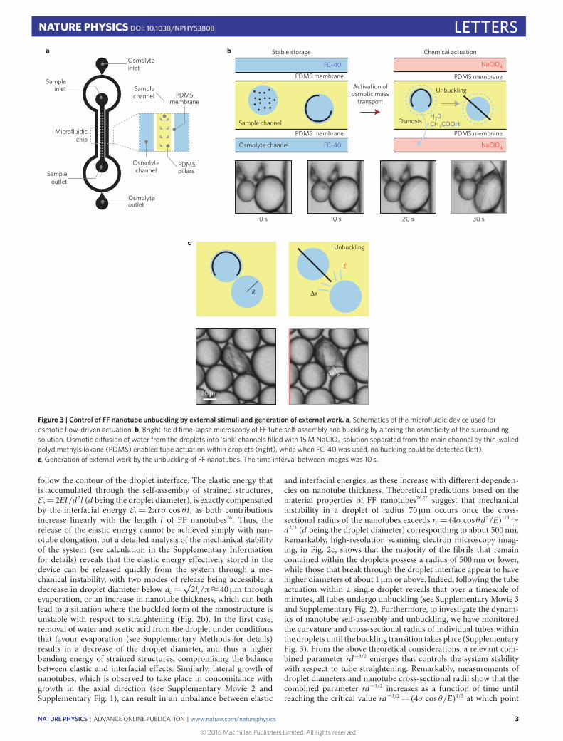
Figure 3 | Control of FF nanotube unbuckling by external stimuli and generation of external work. a, Schematics of the microfluidic device used forosmotic flow-driven actuation. b, Bright-field time-lapse microscopy of FF tube self-assembly and buckling by altering the osmoticity of the surroundingsolution. Osmotic di�usion of water from the droplets into ‘sink’ channels filled with 15 M NaClO4 solution separated from the main channel by thin-walledpolydimethylsiloxane (PDMS) enabled tube actuation within droplets (right), while when FC-40 was used, no buckling could be detected (left).c, Generation of external work by the unbuckling of FF nanotubes. The time interval between images was 10 s.
follow the contour of the droplet interface. The elastic energy thatis accumulated through the self-assembly of strained structures,Eb=2EI/d2l (d being the droplet diameter), is exactly compensatedby the interfacial energy Ei = 2πrσ cos θ l , as both contributionsincrease linearly with the length l of FF nanotubes26. Thus, therelease of the elastic energy cannot be achieved simply with nan-otube elongation, but a detailed analysis of the mechanical stabilityof the system (see calculation in the Supplementary Informationfor details) reveals that the elastic energy effectively stored in thedevice can be released quickly from the system through a me-chanical instability, with two modes of release being accessible: adecrease in droplet diameter below dc=
√2lc/π≈ 40 µm through
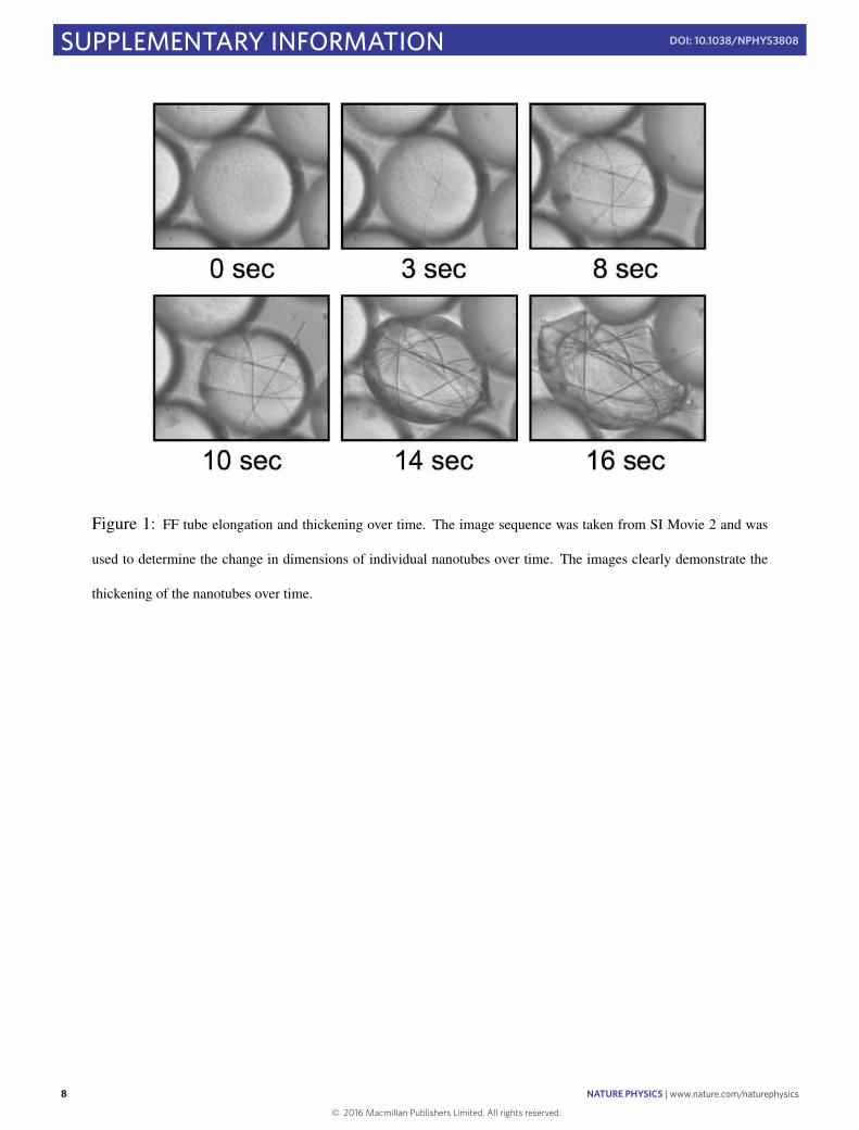
evaporation, or an increase in nanotube thickness, which can bothlead to a situation where the buckled form of the nanostructure isunstable with respect to straightening (Fig. 2b). In the first case,removal of water and acetic acid from the droplet under conditionsthat favour evaporation (see Supplementary Methods for details)results in a decrease of the droplet diameter, and thus a higherbending energy of strained structures, compromising the balancebetween elastic and interfacial effects. Similarly, lateral growth ofnanotubes, which is observed to take place in concomitance withgrowth in the axial direction (see Supplementary Movie 2 andSupplementary Fig. 1), can result in an unbalance between elastic
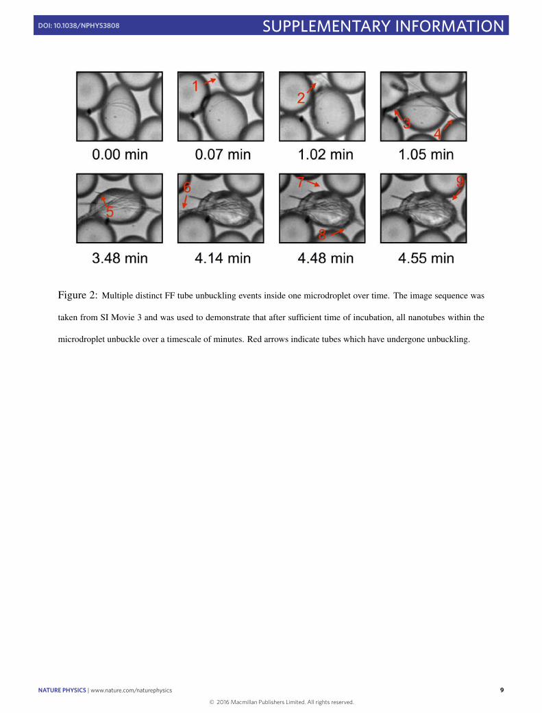
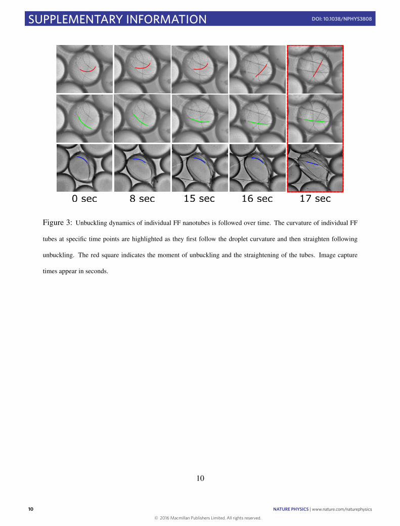
and interfacial energies, as these increase with different dependen-cies on nanotube thickness. Theoretical predictions based on thematerial properties of FF nanotubes26,27 suggest that mechanicalinstability in a droplet of radius 70 µm occurs once the cross-sectional radius of the nanotubes exceeds rc= (4σ cos θd2/E)1/3∼d2/3 (d being the droplet diameter) corresponding to about 500 nm.Remarkably, high-resolution scanning electron microscopy imag-ing, in Fig. 2c, shows that the majority of the fibrils that remaincontained within the droplets possess a radius of 500 nm or lower,while those that break through the droplet interface appear to havehigher diameters of about 1 µmor above. Indeed, following the tubeactuation within a single droplet reveals that over a timescale ofminutes, all tubes undergo unbuckling (see Supplementary Movie 3and Supplementary Fig. 2). Furthermore, to investigate the dynam-ics of nanotube self-assembly and unbuckling, we have monitoredthe curvature and cross-sectional radius of individual tubes withinthe droplets until the buckling transition takes place (SupplementaryFig. 3). From the above theoretical considerations, a relevant com-bined parameter rd−3/2 emerges that controls the system stabilitywith respect to tube straightening. Remarkably, measurements ofdroplet diameters and nanotube cross-sectional radii show that thecombined parameter rd−3/2 increases as a function of time untilreaching the critical value rd−3/2= (4σ cos θ/E)1/3 at which point
NATURE PHYSICS | ADVANCE ONLINE PUBLICATION | www.nature.com/naturephysics
© 2016 Macmillan Publishers Limited. All rights reserved
3
LETTERS NATURE PHYSICS DOI: 10.1038/NPHYS3808
Fungusspores
103
103
102
102
101
101
100
100
10−1
10−1
10−2
10−2
10−3
10−310−4
10−4
Internal combustionengine
Thermal shapememory alloy
Carbon nanotubeactuator
FF nanotubeassembly
Skeletal muscle
Liquid crystalpolymers
Dielectricelastomers
Ionic polymer metal composites
Bacillus spores
500 nm
Venus flytrap/micro hydrogels
Bacterialflagellarmotor
Seed dispersal
Bacteriophages(DNA injection)
Biological, non-self-assembly
Non-biological
Biological, self-assembly
Insulin assembly
Spasmonemespring
Actinassembly
Pow
er d
ensi
ty (W
cm
−3)
Energy density (J cm−3)
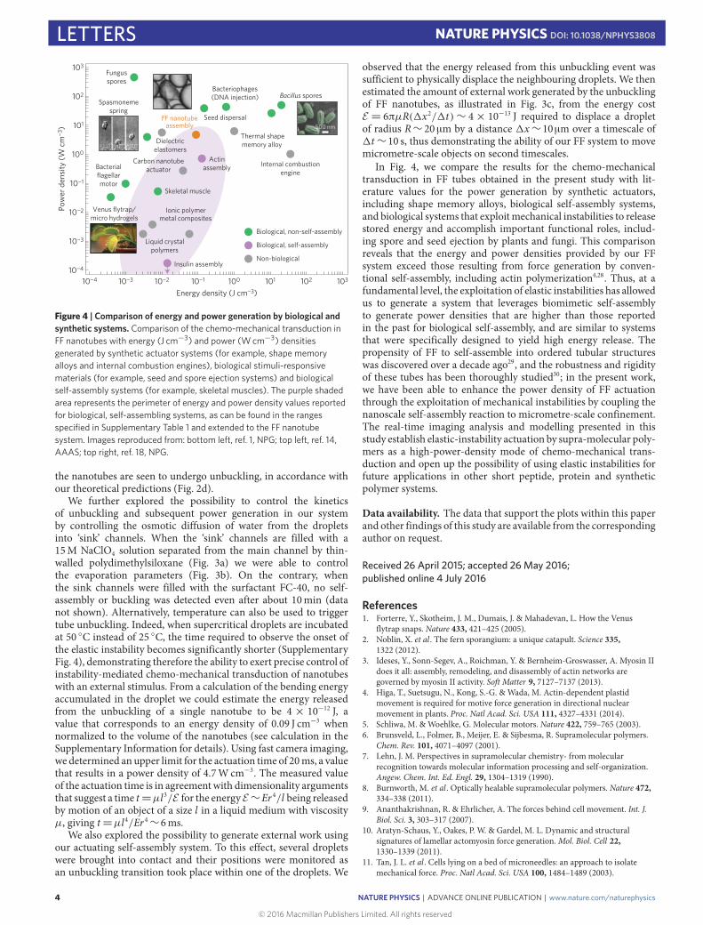
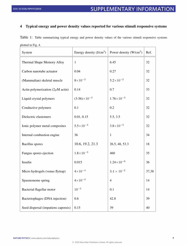
Figure 4 | Comparison of energy and power generation by biological andsynthetic systems. Comparison of the chemo-mechanical transduction inFF nanotubes with energy (J cm−3) and power (W cm−3) densitiesgenerated by synthetic actuator systems (for example, shape memoryalloys and internal combustion engines), biological stimuli-responsivematerials (for example, seed and spore ejection systems) and biologicalself-assembly systems (for example, skeletal muscles). The purple shadedarea represents the perimeter of energy and power density values reportedfor biological, self-assembling systems, as can be found in the rangesspecified in Supplementary Table 1 and extended to the FF nanotubesystem. Images reproduced from: bottom left, ref. 1, NPG; top left, ref. 14,AAAS; top right, ref. 18, NPG.
the nanotubes are seen to undergo unbuckling, in accordance withour theoretical predictions (Fig. 2d).
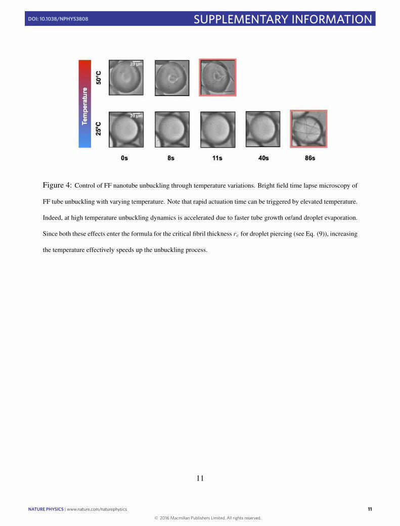
We further explored the possibility to control the kineticsof unbuckling and subsequent power generation in our systemby controlling the osmotic diffusion of water from the dropletsinto ‘sink’ channels. When the ‘sink’ channels are filled with a15M NaClO4 solution separated from the main channel by thin-walled polydimethylsiloxane (Fig. 3a) we were able to controlthe evaporation parameters (Fig. 3b). On the contrary, whenthe sink channels were filled with the surfactant FC-40, no self-assembly or buckling was detected even after about 10min (datanot shown). Alternatively, temperature can also be used to triggertube unbuckling. Indeed, when supercritical droplets are incubatedat 50 ◦C instead of 25 ◦C, the time required to observe the onset ofthe elastic instability becomes significantly shorter (SupplementaryFig. 4), demonstrating therefore the ability to exert precise control ofinstability-mediated chemo-mechanical transduction of nanotubeswith an external stimulus. From a calculation of the bending energyaccumulated in the droplet we could estimate the energy releasedfrom the unbuckling of a single nanotube to be 4× 10⁻¹² J, avalue that corresponds to an energy density of 0.09 J cm−3 whennormalized to the volume of the nanotubes (see calculation in theSupplementary Information for details). Using fast camera imaging,we determined an upper limit for the actuation time of 20ms, a valuethat results in a power density of 4.7Wcm−3. The measured valueof the actuation time is in agreement with dimensionality argumentsthat suggest a time t=µl3/E for the energy E∼Er 4/l being releasedby motion of an object of a size l in a liquid medium with viscosityµ, giving t=µl4/Er 4∼6ms.
We also explored the possibility to generate external work usingour actuating self-assembly system. To this effect, several dropletswere brought into contact and their positions were monitored asan unbuckling transition took place within one of the droplets. We
observed that the energy released from this unbuckling event wassufficient to physically displace the neighbouring droplets. We thenestimated the amount of external work generated by the unbucklingof FF nanotubes, as illustrated in Fig. 3c, from the energy costE = 6πµR(1x2/1t)∼ 4× 10⁻¹³ J required to displace a dropletof radius R∼ 20 µm by a distance 1x∼10µm over a timescale of1t∼10 s, thus demonstrating the ability of our FF system to movemicrometre-scale objects on second timescales.
In Fig. 4, we compare the results for the chemo-mechanicaltransduction in FF tubes obtained in the present study with lit-erature values for the power generation by synthetic actuators,including shape memory alloys, biological self-assembly systems,and biological systems that exploitmechanical instabilities to releasestored energy and accomplish important functional roles, includ-ing spore and seed ejection by plants and fungi. This comparisonreveals that the energy and power densities provided by our FFsystem exceed those resulting from force generation by conven-tional self-assembly, including actin polymerization4,28. Thus, at afundamental level, the exploitation of elastic instabilities has allowedus to generate a system that leverages biomimetic self-assemblyto generate power densities that are higher than those reportedin the past for biological self-assembly, and are similar to systemsthat were specifically designed to yield high energy release. Thepropensity of FF to self-assemble into ordered tubular structureswas discovered over a decade ago29, and the robustness and rigidityof these tubes has been thoroughly studied30; in the present work,we have been able to enhance the power density of FF actuationthrough the exploitation of mechanical instabilities by coupling thenanoscale self-assembly reaction to micrometre-scale confinement.The real-time imaging analysis and modelling presented in thisstudy establish elastic-instability actuation by supra-molecular poly-mers as a high-power-density mode of chemo-mechanical trans-duction and open up the possibility of using elastic instabilities forfuture applications in other short peptide, protein and syntheticpolymer systems.
Data availability. The data that support the plots within this paperand other findings of this study are available from the correspondingauthor on request.
Received 26 April 2015; accepted 26 May 2016;published online 4 July 2016
References1. Forterre, Y., Skotheim, J. M., Dumais, J. & Mahadevan, L. How the Venus
flytrap snaps. Nature 433, 421–425 (2005).2. Noblin, X. et al . The fern sporangium: a unique catapult. Science 335,
1322 (2012).3. Ideses, Y., Sonn-Segev, A., Roichman, Y. & Bernheim-Groswasser, A. Myosin II
does it all: assembly, remodeling, and disassembly of actin networks aregoverned by myosin II activity. Soft Matter 9, 7127–7137 (2013).
4. Higa, T., Suetsugu, N., Kong, S.-G. &Wada, M. Actin-dependent plastidmovement is required for motive force generation in directional nuclearmovement in plants. Proc. Natl Acad. Sci. USA 111, 4327–4331 (2014).
5. Schliwa, M. &Woehlke, G. Molecular motors. Nature 422, 759–765 (2003).6. Brunsveld, L., Folmer, B., Meijer, E. & Sijbesma, R. Supramolecular polymers.
Chem. Rev. 101, 4071–4097 (2001).7. Lehn, J. M. Perspectives in supramolecular chemistry- from molecular
recognition towards molecular information processing and self-organization.Angew. Chem. Int. Ed. Engl. 29, 1304–1319 (1990).
8. Burnworth, M. et al . Optically healable supramolecular polymers. Nature 472,334–338 (2011).
9. Ananthakrishnan, R. & Ehrlicher, A. The forces behind cell movement. Int. J.Biol. Sci. 3, 303–317 (2007).
10. Aratyn-Schaus, Y., Oakes, P. W. & Gardel, M. L. Dynamic and structuralsignatures of lamellar actomyosin force generation.Mol. Biol. Cell 22,1330–1339 (2011).
11. Tan, J. L. et al . Cells lying on a bed of microneedles: an approach to isolatemechanical force. Proc. Natl Acad. Sci. USA 100, 1484–1489 (2003).
4
© 2016 Macmillan Publishers Limited. All rights reserved
NATURE PHYSICS | ADVANCE ONLINE PUBLICATION | www.nature.com/naturephysics
NATURE PHYSICS DOI: 10.1038/NPHYS3808 LETTERS12. Roberts, A. J., Kon, T., Knight, P. J., Sutoh, K. & Burgess, S. A. Functions
and mechanics of dynein motor proteins. Nature Rev. Mol. Cell Biol. 14,713–726 (2013).
13. Granger, E., McNee, G., Allan, V. &Woodman, P. The role of the cytoskeletonand molecular motors in endosomal dynamics. Semin. Cell. Dev. Biol. 31,20–29 (2014).
14. Mahadevan, L. & Matsudaira, P. Motility powered by supramolecular springsand ratchets. Science 288, 95–99 (2000).
15. Krause, M. & Gautreau, A. Steering cell migration: lamellipodium dynamicsand the regulation of directional persistence. Nature Rev. Mol. Cell Biol. 15,577–590 (2014).
16. Amari, K., Di Donato, M., Dolja, V. V. & Heinlein, M. Myosins VIII and XI playdistinct roles in reproduction and transport of tobacco mosaic virus. PLoSPathogens 10, e1004448 (2014).
17. Utada, A. S. et al . Vibrio cholerae use pili and flagella synergistically to effectmotility switching and conditional surface attachment. Nature Commun. 5,4913 (2014).
18. Chen, X., Mahadevan, L., Driks, A. & Sahin, O. Bacillus spores as buildingblocks for stimuli-responsive materials and nanogenerators. Nature Nanotech.9, 137–141 (2014).
19. Sedman, V. L., Adler-Abramovich, L., Allen, S., Gazit, E. & Tendler, S. J. B.Direct observation of the release of phenylalanine from diphenylalaninenanotubes. J. Am. Chem. Soc. 128, 6903–6908 (2006).
20. Hendler, N. et al . Formation of well-organized self-assembled films frompeptide nanotubes. Adv. Mater. 19, 1485–1488 (2007).
21. Guo, C., Luo, Y., Zhou, R. & Wei, G. Probing the self-assembly mechanism ofdiphenylalanine-based peptide nanovesicles and nanotubes. ACS Nano 6,3907–3918 (2012).
22. Kim, J. et al . Role of water in directing diphenylalanine assembly intonanotubes and nanowires. Adv. Mater. 22, 583–587 (2010).
23. Ikezoe, Y., Washino, G., Uemura, T., Kitagawa, S. & Matsui, H. Autonomousmotors of a metalorganic framework powered by reorganization ofself-assembled peptides at interfaces. Nature Mater. 11, 1081–1085 (2012).
24. Hofrichter, J., Ross, P. D. & Eaton, W. A. Kinetics and mechanism ofdeoxyhemoglobin S gelation: a new approach to understanding sickle celldisease. Proc. Natl Acad. Sci. USA 71, 4864–4868 (1974).
25. Kashchiev, D. Nucleation: Basic Theory with Applications (Oxford Univ.Press, 2000).
26. Cohen, A. E. & Mahadevan, L. Kinks, rings, and rackets in filamentousstructures. Proc. Natl Acad. Sci. USA 100, 12141–12146 (2003).
27. Kol, N. et al . Self-assembled peptide nanostructures are uniquely rigidbioinspired supramolecular structures. Nano Lett. 5, 1343–1346 (2005).
28. Hunter, I. & Lafontaine, S. A comparison of muscle with artificial actuatorsTech. Dig. IEEE Solid-State Sensor Actuator WorkshopHilton Head, SouthCarolina 178–185 (1992).
29. Reches, M. & Gazit, E. Casting metal nanowires within discrete self-assembledpeptide nanotubes. Science 300, 625–627 (2003).
30. Adler-Abramovich, L. et al . Thermal and chemical stability of diphenylalaninepeptide nanotubes: implications for nanotechnological applications. Langmuir22, 1313–1320 (2006).
AcknowledgementsThis work was supported by a short-term fellowship from EMBO and from FEBS (A.L.),the Newman Foundation (A.L., T.O.M., T.P.J.K.), the Tel Aviv University Center forNanoscience and Nanotechnology (A.L.), St John’s College Cambridge (T.C.T.M.), theIsraeli National Nanotechnology Initiative and Helmsley Charitable Trust (E.G.), ElanPharmaceuticals (T.O.M.), the UK BBSRC (T.P.J.K.) and the ERC (T.P.J.K., T.C.T.M.). Wethank P. Marcu and Z. Arnon for their assistance with the high-resolution scanningelectron microscopy imaging, and members of the Gazit and Knowles groups forhelpful discussion.
Author contributionsA.L., T.C.T.M., L.M., E.G. and T.P.J.K. conceived and designed the experiments. A.L.,T.O.M., B.Z. and T.C.T.M. planned and performed the experiments. T.C.T.M., L.M. andT.P.J.K. developed the theory and analysed the experimental data. T.M. provided the fastcamera set-up. A.L., T.C.T.M., L.A.-A., T.O.M., T.M., L.M., E.G. and T.P.J.K. wrote themanuscript. All authors discussed the results, provided intellectual input and criticalfeedback and commented on the manuscript.
Additional informationSupplementary information is available in the online version of the paper. Reprints andpermissions information is available online at www.nature.com/reprints.Correspondence and requests for materials should be addressed to E.D. or T.P.J.K.
Competing financial interestsThe authors declare no competing financial interests.
NATURE PHYSICS | ADVANCE ONLINE PUBLICATION | www.nature.com/naturephysics
© 2016 Macmillan Publishers Limited. All rights reserved
5
SUPPLEMENTARY INFORMATIONDOI: 10.1038/NPHYS3808
NATURE PHYSICS | www.nature.com/naturephysics 1
Elastic Instability-Mediated Actuation by a Supra-Molecular Polymer
Aviad Levin1,2,@, Thomas C. T. Michaels2,@, Lihi Adler-Abramovich3, Thomas O. Mason2, Thomas Muller2,
Bohan Zhang2, L. Mahadevan4,5, Ehud Gazit1,6,∗& Tuomas P. J. Knowles2,∗
1Department for Molecular Microbiology and Biotechnology, Tel Aviv University, Tel Aviv 69978, Israel
2Department of Chemistry, University of Cambridge, Lensfield Road, Cambridge, CB2 1EW, UK
3Department of Oral Biology, The Goldschleger School of Dental Medicine, Sackler Faculty of Medicine,
Tel Aviv University, Tel Aviv 69978, Israel.
4School of Engineering and Applied Sciences, Harvard University, Cambridge, MA 02138, USA
5Department of Physics, Harvard University, Cambridge, MA 02138, USA
6Department of Materials Science and Engineering, Tel Aviv University, Tel Aviv 69978, Israel
@Contributed equally to this work.
∗to whom correspondence should be addressed: [email protected] or [email protected].
1 Methods
Peptide solutions H-L-Phe-L-Phe-COOH (FF, Bachem) stock solutions were prepared in acetic acid gala-
cial and then diluted in the required ratios in double distilled water, forming an array of peptide concentra-
tions and solvent compositions. The structural morphologies of the resulting species were then determined
by bright field microscopy and SEM observations.
1
Elastic instability-mediated actuation by a supra-molecular polymer
© 2016 Macmillan Publishers Limited. All rights reserved.
2 NATURE PHYSICS | www.nature.com/naturephysics
SUPPLEMENTARY INFORMATION DOI: 10.1038/NPHYS3808
Microdroplet Formation Microfluidic channels were fabricated in polydimethylsiloxane (PDMS; Dow
Corning), using SU8 on silicon masters and standard soft lithography techniques, and then plasma bonded
to glass slides to create sealed devices. FF stock solutions in acetic acid with a final concentration of 100-300
mg/ml were mixed on chip to form a solution of 50% (v/v) acetic acid in water, and microdroplets containing
FF concentrations of of 50-150 mg/ml were formed in an oil phase of Fluorinert FC-40 (SigmaAldrich,
Gillingham, UK), and 2.0% (w/w) block-copolymer surfactant. Syringe pumps (Cetoni GmbH, Korbussen,
Germany) were used to control the flow of fluids, and the microdroplets were immediately transfered onto a
glass slide and then observed under bright field microscopy as a function of time. While the microdroplets
were monitored the water and acetic acid solution within was seen to evaporate, therefore, microdroplet
volume decreased, leading to the self-assembly of FF into tubes. Droplets formed at a final FF concentration
of 50 mg/ml which formed an array in close contact were monitored for the piercing analysis, while a more
dispersed droplet array formed at an FF concentration of 150 mg/ml were monitored and the buckling and
actuation behavior was analysed.
High-speed bright field microscopy Samples of FF droplets produced as stated above in 1:1 acetic acid:water
ratios were placed on glass slides and were left to self-assemble at room temperature. high-speed image se-
quences of the self-assembly of FF tubes within the droplets were recorded using MotionBLITZ Cube4
(Mikrotron GmbH, Unterschleiheim, Germany) high-speed recording camera.
High Resolution Scanning Electron Microscopy Samples of FF droplets produced as stated above in 1:1
acetic acid:water ratios were placed on glass slides and were left to self-assemble and dry at room temper-
ature. Samples were then coated with Cr and viewed using a JSM-6700 field-emission High Resolution
Scanning Electron Microscope (HR-SEM) (Jeol, Tokyo, Japan), equipped with a cold field emission gun
(CFEG) operating at 1 kV.
2
Microdroplet actuation by temperature Microdroplets were produced as described above and were then
placed on a glass slide. Using a heated microscope stage (MTS120, Microptik BV, Schoondijke, The Nether-
lands), actuation temperature was set to room temperature or at 50 ◦C, and image sequences were acquired
over time.
Data availability statement The source data that support the figures within this paper and other findings
of this study are available from the corresponding author upon request.
2 Estimation of line tension for hole opening
The line energy term F (r) = 2πrγ entering the free energy function for hole opening (see main text) arises
because the membrane has finite width h ∼ 0.1µm; indeed, when a hole of radius r is opened new surface
area is needed to create the rim of the pore. Thus, we can estimate the line tension γ by relating it to the
membrane surface tension through the equation γ = chσ, where c is a geometrical factor of order unity.
For example, for a rim surface modelled as a half-torus (a half-circle of radius h/2 whose center is dragged
around a circle of radius r) the energy cost associated with the formation of the rim is estimated as
Frim(r) = 2π2r(h/2)σ = 2πr(σhπ/2) ≡ 2πrγ. (1)
Therefore, for this specific rim geometry, the relationship between line and surface tension can be estimated
as γ = σhπ/2 ∼ σh.
3 Detailed calculation for spring-like piercing of oil-water interface by FF tubes
This appendix presents detailed calculations for the spring-like piercing of oil-water interfaces by FF tubes
described in Figs. 2 and 3 of the main text.
3
© 2016 Macmillan Publishers Limited. All rights reserved.
NATURE PHYSICS | www.nature.com/naturephysics 3
SUPPLEMENTARY INFORMATIONDOI: 10.1038/NPHYS3808
Microdroplet Formation Microfluidic channels were fabricated in polydimethylsiloxane (PDMS; Dow
Corning), using SU8 on silicon masters and standard soft lithography techniques, and then plasma bonded
to glass slides to create sealed devices. FF stock solutions in acetic acid with a final concentration of 100-300
mg/ml were mixed on chip to form a solution of 50% (v/v) acetic acid in water, and microdroplets containing
FF concentrations of of 50-150 mg/ml were formed in an oil phase of Fluorinert FC-40 (SigmaAldrich,
Gillingham, UK), and 2.0% (w/w) block-copolymer surfactant. Syringe pumps (Cetoni GmbH, Korbussen,
Germany) were used to control the flow of fluids, and the microdroplets were immediately transfered onto a
glass slide and then observed under bright field microscopy as a function of time. While the microdroplets
were monitored the water and acetic acid solution within was seen to evaporate, therefore, microdroplet
volume decreased, leading to the self-assembly of FF into tubes. Droplets formed at a final FF concentration
of 50 mg/ml which formed an array in close contact were monitored for the piercing analysis, while a more
dispersed droplet array formed at an FF concentration of 150 mg/ml were monitored and the buckling and
actuation behavior was analysed.
High-speed bright field microscopy Samples of FF droplets produced as stated above in 1:1 acetic acid:water
ratios were placed on glass slides and were left to self-assemble at room temperature. high-speed image se-
quences of the self-assembly of FF tubes within the droplets were recorded using MotionBLITZ Cube4
(Mikrotron GmbH, Unterschleiheim, Germany) high-speed recording camera.
High Resolution Scanning Electron Microscopy Samples of FF droplets produced as stated above in 1:1
acetic acid:water ratios were placed on glass slides and were left to self-assemble and dry at room temper-
ature. Samples were then coated with Cr and viewed using a JSM-6700 field-emission High Resolution
Scanning Electron Microscope (HR-SEM) (Jeol, Tokyo, Japan), equipped with a cold field emission gun
(CFEG) operating at 1 kV.
2
Microdroplet actuation by temperature Microdroplets were produced as described above and were then
placed on a glass slide. Using a heated microscope stage (MTS120, Microptik BV, Schoondijke, The Nether-
lands), actuation temperature was set to room temperature or at 50 ◦C, and image sequences were acquired
over time.
Data availability statement The source data that support the figures within this paper and other findings
of this study are available from the corresponding author upon request.
2 Estimation of line tension for hole opening
The line energy term F (r) = 2πrγ entering the free energy function for hole opening (see main text) arises
because the membrane has finite width h ∼ 0.1µm; indeed, when a hole of radius r is opened new surface
area is needed to create the rim of the pore. Thus, we can estimate the line tension γ by relating it to the
membrane surface tension through the equation γ = chσ, where c is a geometrical factor of order unity.
For example, for a rim surface modelled as a half-torus (a half-circle of radius h/2 whose center is dragged
around a circle of radius r) the energy cost associated with the formation of the rim is estimated as
Frim(r) = 2π2r(h/2)σ = 2πr(σhπ/2) ≡ 2πrγ. (1)
Therefore, for this specific rim geometry, the relationship between line and surface tension can be estimated
as γ = σhπ/2 ∼ σh.
3 Detailed calculation for spring-like piercing of oil-water interface by FF tubes
This appendix presents detailed calculations for the spring-like piercing of oil-water interfaces by FF tubes
described in Figs. 2 and 3 of the main text.
3
© 2016 Macmillan Publishers Limited. All rights reserved.
4 NATURE PHYSICS | www.nature.com/naturephysics
SUPPLEMENTARY INFORMATION DOI: 10.1038/NPHYS3808
Filament buckling When a growing filament of length l > d comes in contact with the surface of the water
droplet (diameter d ≈ 140µm), the liquid oil-water interface exerts a compression force of magnitude
Fc = 2πrσ cos θ, (2)
with r[m] being the radius of the filament cross section, σ[N/m] the oil-water surface tension and θ the in-
terface contact angle.1 Filament buckling occurs when this compression force Fc exceeds the Euler buckling
load
Fb =EIπ2
l2, (3)
where EI is the bending rigidity, E[Pa] the Young modulus, I[m4]= πr4/4 the area moment of inertia
measured along the axis of symmetry of the filament, and l[m] the length of the rod. Thus, equating Eqs. (2)
and (3) shows that interfacial effects cause the filament to bend if l > lc, where the critical length lc is given
by26
lc =
(πEI
2rσ cos θ
)1/2
=
(π2Er3
8σ cos θ
)1/2
. (4)
For typical values in our experiment, E = 20 GPa, r = 0.2µm, σ = 20mN/m and cos θ ∼ 1, we find
lc ≈ 100 µm. Because lc < d, filaments buckle as soon as they come in contact with the droplet surface.
Piercing of droplet interface Once the tube length l exceeds the buckling limit lc, what determines whether
the filament will continue growing in the form of a ring or it will eventually pierce the liquid interface by
returning to the straight state is the balance between the bending energy of the rod
Eb =2EI
d2l (5)
and the interfacial energy
Ei = −2πrσ cos θ l. (6)
4
The condition for piercing, ∂(Eb + Ei)/∂l = 0, yields with Eqs. (5) and (6)
lcd=
π√2. (7)
Remarkably, Eq. (7) shows that the tube length l drops out of the piercing condition. This is because both
the bending and interfacial energies increase linearly with tube length l. Therefore, linear filament growth is
unlikely to produce a large driving force for droplet rupture, but two additional effects are potentially very
important (see Figure 2d):
(i) droplet drying and the associated change in diameter; indeed, according to Eq. (7), when the droplet
diameter d is reduced below the value
dc =
√2
πlc ≈ 45 µm (8)
tubes snap;
(ii) thickening of the nanotubes during growth; indeed, lc ∼ r3/2 increases with increasing tube radius.
The critical fibril thickness for piercing is
rc =
(4σ cos θd2
E
)1/3
≈ 0.4 µm. (9)
Note that from the piercing condition lc ∼ d and the scaling relationship lc ∼ r3/2, we find rc ∼ d2/3.
Using these values, the strength of the forces involved in the actuation process is
F = 2πrcσ cos θ ≈ 54 nN, (10)
corresponding to an energy density of
U =Ei
πr2c l=
F
πr2c≈ 0.09 J cm−3. (11)
5
© 2016 Macmillan Publishers Limited. All rights reserved.
NATURE PHYSICS | www.nature.com/naturephysics 5
SUPPLEMENTARY INFORMATIONDOI: 10.1038/NPHYS3808
Filament buckling When a growing filament of length l > d comes in contact with the surface of the water
droplet (diameter d ≈ 140µm), the liquid oil-water interface exerts a compression force of magnitude
Fc = 2πrσ cos θ, (2)
with r[m] being the radius of the filament cross section, σ[N/m] the oil-water surface tension and θ the in-
terface contact angle.1 Filament buckling occurs when this compression force Fc exceeds the Euler buckling
load
Fb =EIπ2
l2, (3)
where EI is the bending rigidity, E[Pa] the Young modulus, I[m4]= πr4/4 the area moment of inertia
measured along the axis of symmetry of the filament, and l[m] the length of the rod. Thus, equating Eqs. (2)
and (3) shows that interfacial effects cause the filament to bend if l > lc, where the critical length lc is given
by26
lc =
(πEI
2rσ cos θ
)1/2
=
(π2Er3
8σ cos θ
)1/2
. (4)
For typical values in our experiment, E = 20 GPa, r = 0.2µm, σ = 20mN/m and cos θ ∼ 1, we find
lc ≈ 100 µm. Because lc < d, filaments buckle as soon as they come in contact with the droplet surface.
Piercing of droplet interface Once the tube length l exceeds the buckling limit lc, what determines whether
the filament will continue growing in the form of a ring or it will eventually pierce the liquid interface by
returning to the straight state is the balance between the bending energy of the rod
Eb =2EI
d2l (5)
and the interfacial energy
Ei = −2πrσ cos θ l. (6)
4
The condition for piercing, ∂(Eb + Ei)/∂l = 0, yields with Eqs. (5) and (6)
lcd=
π√2. (7)
Remarkably, Eq. (7) shows that the tube length l drops out of the piercing condition. This is because both
the bending and interfacial energies increase linearly with tube length l. Therefore, linear filament growth is
unlikely to produce a large driving force for droplet rupture, but two additional effects are potentially very
important (see Figure 2d):
(i) droplet drying and the associated change in diameter; indeed, according to Eq. (7), when the droplet
diameter d is reduced below the value
dc =
√2
πlc ≈ 45 µm (8)
tubes snap;
(ii) thickening of the nanotubes during growth; indeed, lc ∼ r3/2 increases with increasing tube radius.
The critical fibril thickness for piercing is
rc =
(4σ cos θd2
E
)1/3
≈ 0.4 µm. (9)
Note that from the piercing condition lc ∼ d and the scaling relationship lc ∼ r3/2, we find rc ∼ d2/3.
Using these values, the strength of the forces involved in the actuation process is
F = 2πrcσ cos θ ≈ 54 nN, (10)
corresponding to an energy density of
U =Ei
πr2c l=
F
πr2c≈ 0.09 J cm−3. (11)
5
© 2016 Macmillan Publishers Limited. All rights reserved.
6 NATURE PHYSICS | www.nature.com/naturephysics
SUPPLEMENTARY INFORMATION DOI: 10.1038/NPHYS3808
Actuation time scale The characteristic time scale for actuation (tube snapping in a viscous fluid of vis-
cosity µ ∼ 10−3 N s/m2) can be estimated through a scaling argument by balancing contributions from the
elastic force on an infinitesimal rod element of length ds
dFb = EI∂4ϕ(s, t)
∂s4ds (12)
and the viscous drag
dFd = µ∂ϕ(s, t)
∂tds (13)
where ϕ(s, t) denotes the deflection of the filament. Equating Eqs. (12) and (13) yields the equation of
motion
∂ϕ(s, t)
∂t=
EI
µ
∂4ϕ(s, t)
∂s4(14)
and, thus, the characteristic time scale for rod bending in a viscous fluid as
τ ∼ µ
E
(l
r
)4
∼ 6 ms, (15)
where we used the formula for the moment of inertia of a rod, I = πr4/4. We note that our scaling argument,
Eq. (15), neglects the contribution of tube radius r on the drag force. In the limit r � l, however, this effect
results into a correction of the form τ ∼ µ/E(l/r)2/ log(l/r). 31
6
4 Typical energy and power density values reported for various stimuli responsive systems
Table 1: Table summarizing typical energy and power density values of the various stimuli responsive systems
plotted in Fig. 4.
System Energy density (J/cm3) Power density (W/cm3) Ref.
Thermal Shape Memory Alloy 1 6.45 32
Carbon nanotube actuator 0.04 0.27 32
(Mammalian) skeletal muscle 8×10⁻³ 5.2×10⁻² 32
Actin polymerization (2µM actin) 0.14 0.7 33
Liquid crystal polymers (3-56)×10−3 1.76×10⁻³ 32
Conductive polymers 0.1 0.2 32
Dielectric elastomers 0.01, 0.15 5.5, 3.5 32
Ionic polymer metal composites 5.5×10⁻³ 3.8×10⁻³ 32
Internal combustion engine 36 1 34
Bacillus spores 10.6, 19.2, 21.3 26.5, 48, 53.3 18
Fungus spores ejection 1.8×10⁻³ 460 35
Insulin 0.015 1.24×10⁻⁶ 36
Micro hydrogels (venus flytrap) 4×10⁻⁴ 3.4× 10⁻² 37,38
Spasmoneme spring 4×10⁻³ 4 14
Bacterial flagellar motor 10−3 0.1 14
Bacteriophages (DNA injection) 0.6 42.8 39
Seed dispersal (impatiens capensis) 0.15 39 40
7
© 2016 Macmillan Publishers Limited. All rights reserved.
NATURE PHYSICS | www.nature.com/naturephysics 7
SUPPLEMENTARY INFORMATIONDOI: 10.1038/NPHYS3808
Actuation time scale The characteristic time scale for actuation (tube snapping in a viscous fluid of vis-
cosity µ ∼ 10−3 N s/m2) can be estimated through a scaling argument by balancing contributions from the
elastic force on an infinitesimal rod element of length ds
dFb = EI∂4ϕ(s, t)
∂s4ds (12)
and the viscous drag
dFd = µ∂ϕ(s, t)
∂tds (13)
where ϕ(s, t) denotes the deflection of the filament. Equating Eqs. (12) and (13) yields the equation of
motion
∂ϕ(s, t)
∂t=
EI
µ
∂4ϕ(s, t)
∂s4(14)
and, thus, the characteristic time scale for rod bending in a viscous fluid as
τ ∼ µ
E
(l
r
)4
∼ 6 ms, (15)
where we used the formula for the moment of inertia of a rod, I = πr4/4. We note that our scaling argument,
Eq. (15), neglects the contribution of tube radius r on the drag force. In the limit r � l, however, this effect
results into a correction of the form τ ∼ µ/E(l/r)2/ log(l/r). 31
6
4 Typical energy and power density values reported for various stimuli responsive systems
Table 1: Table summarizing typical energy and power density values of the various stimuli responsive systems
plotted in Fig. 4.
System Energy density (J/cm3) Power density (W/cm3) Ref.
Thermal Shape Memory Alloy 1 6.45 32
Carbon nanotube actuator 0.04 0.27 32
(Mammalian) skeletal muscle 8×10⁻³ 5.2×10⁻² 32
Actin polymerization (2µM actin) 0.14 0.7 33
Liquid crystal polymers (3-56)×10−3 1.76×10⁻³ 32
Conductive polymers 0.1 0.2 32
Dielectric elastomers 0.01, 0.15 5.5, 3.5 32
Ionic polymer metal composites 5.5×10⁻³ 3.8×10⁻³ 32
Internal combustion engine 36 1 34
Bacillus spores 10.6, 19.2, 21.3 26.5, 48, 53.3 18
Fungus spores ejection 1.8×10⁻³ 460 35
Insulin 0.015 1.24×10⁻⁶ 36
Micro hydrogels (venus flytrap) 4×10⁻⁴ 3.4× 10⁻² 37,38
Spasmoneme spring 4×10⁻³ 4 14
Bacterial flagellar motor 10−3 0.1 14
Bacteriophages (DNA injection) 0.6 42.8 39
Seed dispersal (impatiens capensis) 0.15 39 40
7
© 2016 Macmillan Publishers Limited. All rights reserved.
8 NATURE PHYSICS | www.nature.com/naturephysics
SUPPLEMENTARY INFORMATION DOI: 10.1038/NPHYS3808
Figure 1: FF tube elongation and thickening over time. The image sequence was taken from SI Movie 2 and was
used to determine the change in dimensions of individual nanotubes over time. The images clearly demonstrate the
thickening of the nanotubes over time.
8
Figure 2: Multiple distinct FF tube unbuckling events inside one microdroplet over time. The image sequence was
taken from SI Movie 3 and was used to demonstrate that after sufficient time of incubation, all nanotubes within the
microdroplet unbuckle over a timescale of minutes. Red arrows indicate tubes which have undergone unbuckling.
9
© 2016 Macmillan Publishers Limited. All rights reserved.
NATURE PHYSICS | www.nature.com/naturephysics 9
SUPPLEMENTARY INFORMATIONDOI: 10.1038/NPHYS3808
Figure 1: FF tube elongation and thickening over time. The image sequence was taken from SI Movie 2 and was
used to determine the change in dimensions of individual nanotubes over time. The images clearly demonstrate the
thickening of the nanotubes over time.
8
Figure 2: Multiple distinct FF tube unbuckling events inside one microdroplet over time. The image sequence was
taken from SI Movie 3 and was used to demonstrate that after sufficient time of incubation, all nanotubes within the
microdroplet unbuckle over a timescale of minutes. Red arrows indicate tubes which have undergone unbuckling.
9
© 2016 Macmillan Publishers Limited. All rights reserved.
10 NATURE PHYSICS | www.nature.com/naturephysics
SUPPLEMENTARY INFORMATION DOI: 10.1038/NPHYS3808
0 sec 8 sec 15 sec 16 sec 17 sec
Figure 3: Unbuckling dynamics of individual FF nanotubes is followed over time. The curvature of individual FF
tubes at specific time points are highlighted as they first follow the droplet curvature and then straighten following
unbuckling. The red square indicates the moment of unbuckling and the straightening of the tubes. Image capture
times appear in seconds.
10
Figure 4: Control of FF nanotube unbuckling through temperature variations. Bright field time lapse microscopy of
FF tube unbuckling with varying temperature. Note that rapid actuation time can be triggered by elevated temperature.
Indeed, at high temperature unbuckling dynamics is accelerated due to faster tube growth or/and droplet evaporation.
Since both these effects enter the formula for the critical fibril thickness rc for droplet piercing (see Eq. (9)), increasing
the temperature effectively speeds up the unbuckling process.
11
© 2016 Macmillan Publishers Limited. All rights reserved.
NATURE PHYSICS | www.nature.com/naturephysics 11
SUPPLEMENTARY INFORMATIONDOI: 10.1038/NPHYS3808
0 sec 8 sec 15 sec 16 sec 17 sec
Figure 3: Unbuckling dynamics of individual FF nanotubes is followed over time. The curvature of individual FF
tubes at specific time points are highlighted as they first follow the droplet curvature and then straighten following
unbuckling. The red square indicates the moment of unbuckling and the straightening of the tubes. Image capture
times appear in seconds.
10
Figure 4: Control of FF nanotube unbuckling through temperature variations. Bright field time lapse microscopy of
FF tube unbuckling with varying temperature. Note that rapid actuation time can be triggered by elevated temperature.
Indeed, at high temperature unbuckling dynamics is accelerated due to faster tube growth or/and droplet evaporation.
Since both these effects enter the formula for the critical fibril thickness rc for droplet piercing (see Eq. (9)), increasing
the temperature effectively speeds up the unbuckling process.
11
© 2016 Macmillan Publishers Limited. All rights reserved.
12 NATURE PHYSICS | www.nature.com/naturephysics
SUPPLEMENTARY INFORMATION DOI: 10.1038/NPHYS3808
5 References
14. Mahadevan, L., Matsudaira. P. Motility powered by supramolecular springs and ratchets. Science 288,
95-99 (2000).
18. Chen, X., Mahadevan, L., Driks, A. Sahin, O. Bacillus spores as building blocks for stimuli- responsive
materials and nanogenerators. Nat. Nanotechnol. 9, 137–141 (2014).
26. Cohen, A. E. Mahadevan, L. Kinks, rings, and rackets in filamentous structures. Proc. Natl. Acad. Sci.
U.S.A. 100, 12141–12146 (2003).
31. Powers T.R., Dynamics of filaments and membranes in a viscous fluid. Rev. Mod. Phys. 82, 1607–1631
(2010).
32. Madden, J. D. W. et al. Artificial muscle technology: physical principles and naval prospects. J. Oceanic
Eng. 29, 706–728 (2004).
33. Footer, M.J., Kerssemakers, J.W.J., Theriot, J.A. Dogterom, M. Direct measurement of force generation
by actin filament polymerization using an optical trap.Proc. Natl. Acad. Sci. U.S.A. 104, 2181-2186 (2007).
34. Madden, J. D. Mobile robots: Motor challenges and materials solutions. Science 318, 1094 (2007).
35. Noblin, X., Yang, S. Dumais, J. Surface tension propulsion of fungal spores. J. Exp. Biol. 212, 2835–
2843 (2009).
36. Herling, T.W. et al. Force generation by the growth of amyloid aggregates. Proc. Natl. Acad. Sci.
U.S.A. 112, 9524–9529 (2015).
37. Lee, H., Xia, C. Fang, N. X. First jump of microgel: Actuation speed enhancement by elastic instability.
Soft Matter 6, 4342–4345 (2010).
38. Skotheim, J.M. Mahadevan L. Physical limits and design principles for plant and fungal movements.
Science 308, 1308–1310 (2005).
12
39. Smith, D.E., Tans, S.J., Smith, S.B., Grimes, S., Anderson, D.L., Bustamante C. The bacteriophage φ29
portal motor can package DNA against a large internal force. Nature 413, 748-752 (2001).
40. Hayashi, M., Feilich, K.L., Ellerby, D.J. The mechanics of explosive seed dispersal in orange jewelweed
(Impatiens capensis). J. Exp. Bot. 60, 20452053 (2009).
13
© 2016 Macmillan Publishers Limited. All rights reserved.
NATURE PHYSICS | www.nature.com/naturephysics 13
SUPPLEMENTARY INFORMATIONDOI: 10.1038/NPHYS3808
5 References
14. Mahadevan, L., Matsudaira. P. Motility powered by supramolecular springs and ratchets. Science 288,
95-99 (2000).
18. Chen, X., Mahadevan, L., Driks, A. Sahin, O. Bacillus spores as building blocks for stimuli- responsive
materials and nanogenerators. Nat. Nanotechnol. 9, 137–141 (2014).
26. Cohen, A. E. Mahadevan, L. Kinks, rings, and rackets in filamentous structures. Proc. Natl. Acad. Sci.
U.S.A. 100, 12141–12146 (2003).
31. Powers T.R., Dynamics of filaments and membranes in a viscous fluid. Rev. Mod. Phys. 82, 1607–1631
(2010).
32. Madden, J. D. W. et al. Artificial muscle technology: physical principles and naval prospects. J. Oceanic
Eng. 29, 706–728 (2004).
33. Footer, M.J., Kerssemakers, J.W.J., Theriot, J.A. Dogterom, M. Direct measurement of force generation
by actin filament polymerization using an optical trap.Proc. Natl. Acad. Sci. U.S.A. 104, 2181-2186 (2007).
34. Madden, J. D. Mobile robots: Motor challenges and materials solutions. Science 318, 1094 (2007).
35. Noblin, X., Yang, S. Dumais, J. Surface tension propulsion of fungal spores. J. Exp. Biol. 212, 2835–
2843 (2009).
36. Herling, T.W. et al. Force generation by the growth of amyloid aggregates. Proc. Natl. Acad. Sci.
U.S.A. 112, 9524–9529 (2015).
37. Lee, H., Xia, C. Fang, N. X. First jump of microgel: Actuation speed enhancement by elastic instability.
Soft Matter 6, 4342–4345 (2010).
38. Skotheim, J.M. Mahadevan L. Physical limits and design principles for plant and fungal movements.
Science 308, 1308–1310 (2005).
12
39. Smith, D.E., Tans, S.J., Smith, S.B., Grimes, S., Anderson, D.L., Bustamante C. The bacteriophage φ29
portal motor can package DNA against a large internal force. Nature 413, 748-752 (2001).
40. Hayashi, M., Feilich, K.L., Ellerby, D.J. The mechanics of explosive seed dispersal in orange jewelweed
(Impatiens capensis). J. Exp. Bot. 60, 20452053 (2009).
13
© 2016 Macmillan Publishers Limited. All rights reserved.