ELEC351 Lecture Notes Set 1 There is a tutorial on Monday September 10! You will do the first “workshop problem” in the tutorial. Bring a calculator. The course web site is: www.ece.concordia.ca/~trueman/web_page_351.htm • Course outline • Lecture notes • Software: BOUNCE, TRLINE, WAVES
Transcript
ELEC351 Lecture Notes Set 1There is a tutorial on Monday September 10! You will do the first “workshop problem” in the tutorial. Bring a calculator.
The course web site is:www.ece.concordia.ca/~trueman/web_page_351.htm
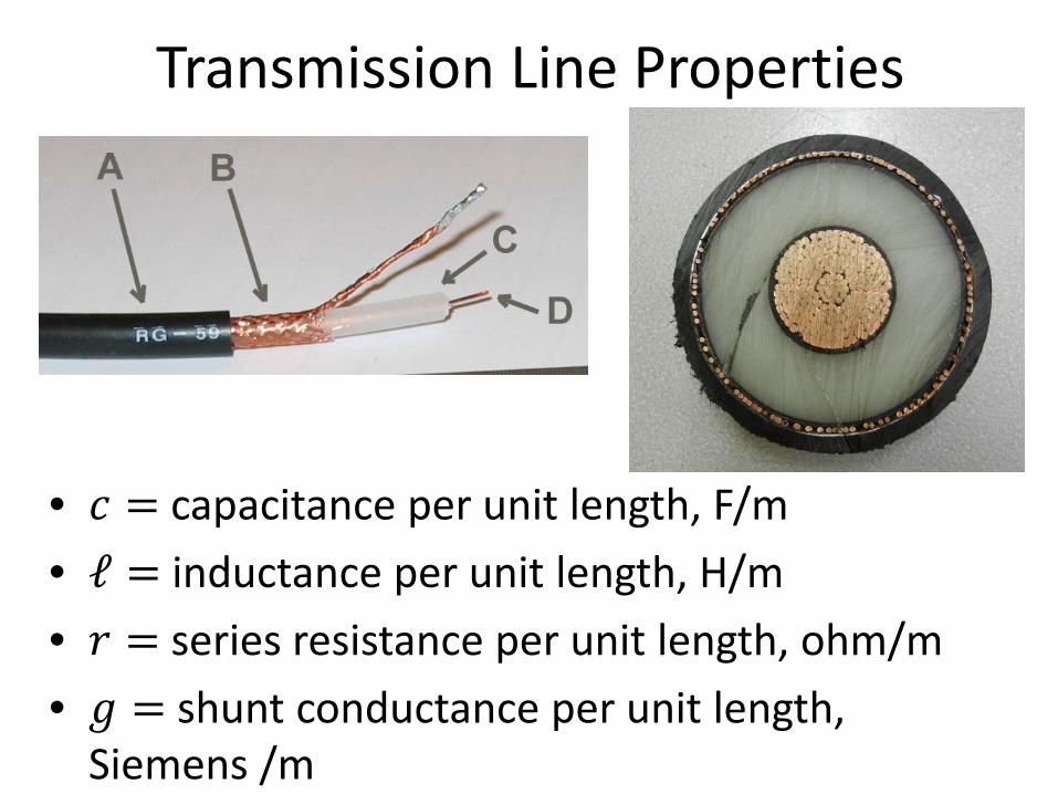
• 𝑐𝑐 = capacitance per unit length, F/m• ℓ = inductance per unit length, H/m• 𝑟𝑟 = series resistance per unit length, ohm/m• 𝑔𝑔 = shunt conductance per unit length,
Siemens /m
7
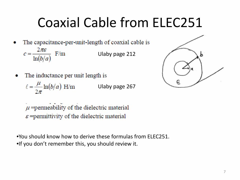
Coaxial Cable from ELEC251
•You should know how to derive these formulas from ELEC251.•If you don’t remember this, you should review it.
Ulaby page 212
Ulaby page 267
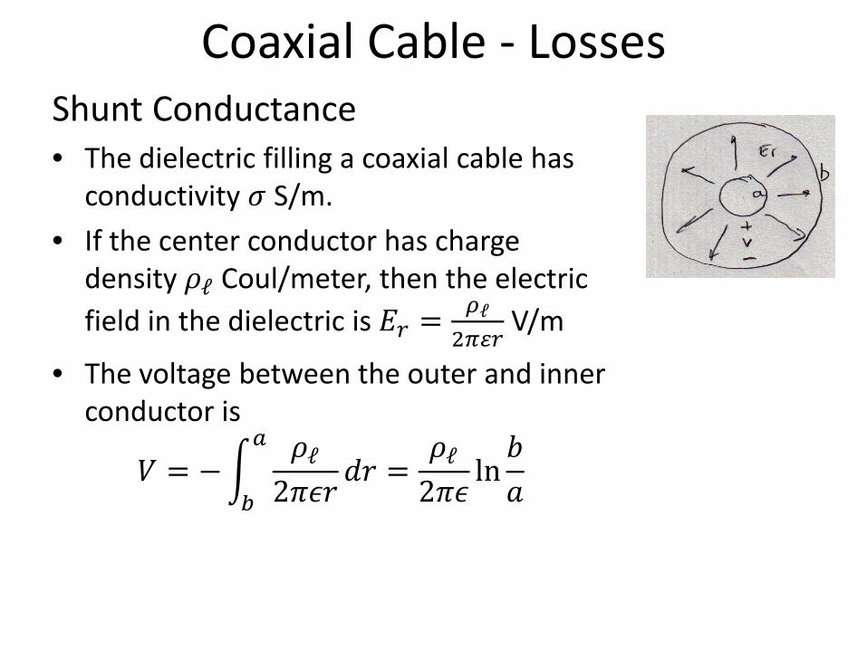
Coaxial Cable - LossesShunt Conductance • The dielectric filling a coaxial cable has
conductivity 𝜎𝜎 S/m.• If the center conductor has charge
density 𝜌𝜌ℓ Coul/meter, then the electric field in the dielectric is 𝐸𝐸𝑟𝑟 = 𝜌𝜌ℓ
2𝜋𝜋𝜋𝜋𝑟𝑟V/m
• The voltage between the outer and inner conductor is
𝑉𝑉 = −�𝑏𝑏
𝑎𝑎 𝜌𝜌ℓ2𝜋𝜋𝜋𝜋𝑟𝑟
𝑑𝑑𝑟𝑟 =𝜌𝜌ℓ2𝜋𝜋𝜋𝜋
ln𝑏𝑏𝑎𝑎
Shunt Conductance, continued• Since 𝐽𝐽 = 𝜎𝜎𝐸𝐸, the current density in the
dielectric is
𝐽𝐽𝑟𝑟 = 𝜎𝜎𝐸𝐸𝑟𝑟 =𝜎𝜎𝜌𝜌ℓ
2𝜋𝜋𝜋𝜋𝑟𝑟• The current flowing through the surface of a
cylinder of length 1 meter and radius 𝑟𝑟 is
𝐼𝐼 = 1 meter 𝑥𝑥 �0
2𝜋𝜋𝐽𝐽𝑟𝑟𝑟𝑟𝑑𝑑𝜙𝜙
= �0
2𝜋𝜋 𝜎𝜎𝜌𝜌ℓ2𝜋𝜋𝜋𝜋𝑟𝑟
𝑟𝑟𝑑𝑑𝜙𝜙 = 2𝜋𝜋𝜎𝜎𝜌𝜌ℓ2𝜋𝜋𝜋𝜋
=𝜎𝜎𝜌𝜌ℓ𝜋𝜋
• The resistance of a 1 m length of cable is
𝑅𝑅 =𝑉𝑉𝐼𝐼
=𝜌𝜌ℓ2𝜋𝜋𝜋𝜋 ln 𝑏𝑏𝑎𝑎𝜎𝜎𝜌𝜌ℓ𝜋𝜋
=ln 𝑏𝑏𝑎𝑎2𝜋𝜋𝜎𝜎
• Hence the conductance of a 1 m length of cable is
𝑔𝑔 = 1𝑅𝑅
= 2𝜋𝜋𝜎𝜎
ln𝑏𝑏𝑎𝑎
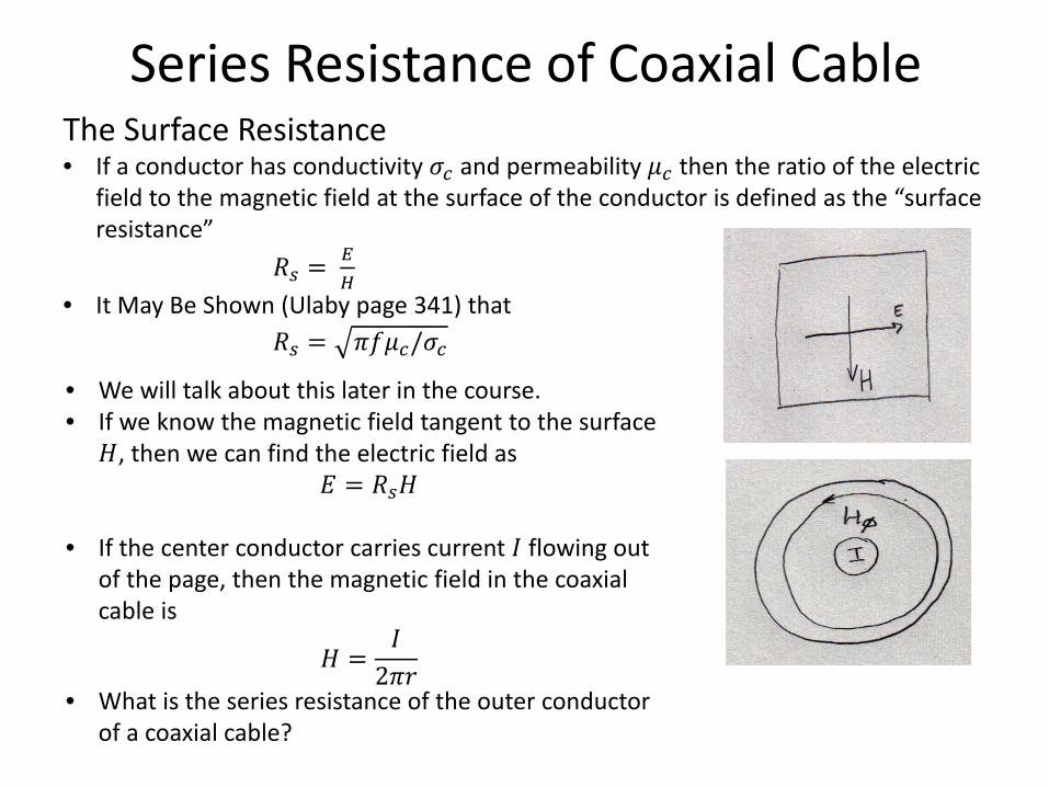
Series Resistance of Coaxial CableThe Surface Resistance • If a conductor has conductivity 𝜎𝜎𝑐𝑐 and permeability 𝜇𝜇𝑐𝑐 then the ratio of the electric
field to the magnetic field at the surface of the conductor is defined as the “surface resistance”
𝑅𝑅𝑠𝑠 = 𝐸𝐸𝐻𝐻
• It May Be Shown (Ulaby page 341) that 𝑅𝑅𝑠𝑠 = 𝜋𝜋𝜋𝜋𝜇𝜇𝑐𝑐/𝜎𝜎𝑐𝑐
• We will talk about this later in the course. • If we know the magnetic field tangent to the surface
𝐻𝐻, then we can find the electric field as 𝐸𝐸 = 𝑅𝑅𝑠𝑠𝐻𝐻
• If the center conductor carries current 𝐼𝐼 flowing out of the page, then the magnetic field in the coaxial cable is
𝐻𝐻 =𝐼𝐼2𝜋𝜋𝑟𝑟
• What is the series resistance of the outer conductor of a coaxial cable?
Series Resistance of Coaxial Cable, continued• At the surface of the outer conductor 𝑟𝑟 = 𝑏𝑏 the
magnetic field is
𝐻𝐻 =𝐼𝐼
2𝜋𝜋𝑏𝑏• The electric field is
𝐸𝐸 = 𝑅𝑅𝑠𝑠𝐻𝐻 = 𝑅𝑅𝑠𝑠𝐼𝐼
2𝜋𝜋𝑏𝑏• The field is oriented axially along the cable.• The voltage across a 1 meter length of cable is
𝑉𝑉 = electric field 𝑥𝑥 distance
= 𝑅𝑅𝑠𝑠𝐼𝐼
2𝜋𝜋𝑏𝑏𝑥𝑥1 meter = 𝑅𝑅𝑠𝑠
𝐼𝐼2𝜋𝜋𝑏𝑏
• The resistance of the 1 meter length of outer conductor is
𝑅𝑅𝑜𝑜𝑜𝑜𝑜𝑜𝑜𝑜𝑟𝑟 =𝑉𝑉𝐼𝐼
=𝑅𝑅𝑠𝑠
𝐼𝐼2𝜋𝜋𝑏𝑏𝐼𝐼
=𝑅𝑅𝑠𝑠2𝜋𝜋𝑏𝑏
• Similarly the resistance of the inner conductor is
𝑅𝑅𝑖𝑖𝑖𝑖𝑖𝑖𝑜𝑜𝑟𝑟 =𝑅𝑅𝑠𝑠2𝜋𝜋𝑎𝑎
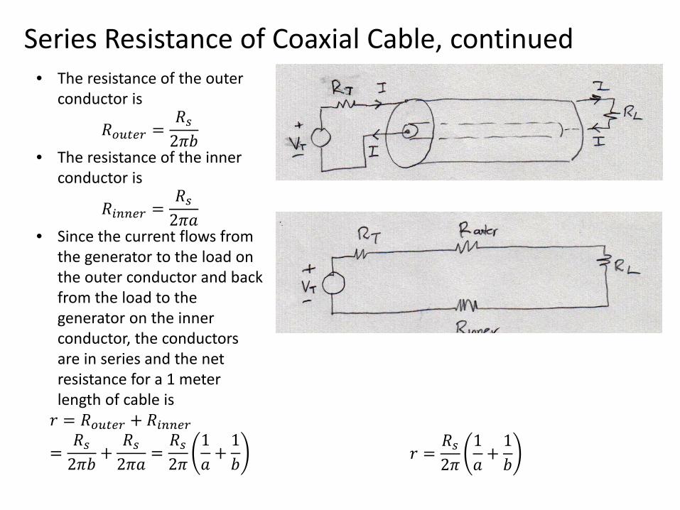
Series Resistance of Coaxial Cable, continued• The resistance of the outer
conductor is
𝑅𝑅𝑜𝑜𝑜𝑜𝑜𝑜𝑜𝑜𝑟𝑟 =𝑅𝑅𝑠𝑠2𝜋𝜋𝑏𝑏
• The resistance of the inner conductor is
𝑅𝑅𝑖𝑖𝑖𝑖𝑖𝑖𝑜𝑜𝑟𝑟 =𝑅𝑅𝑠𝑠2𝜋𝜋𝑎𝑎
• Since the current flows from the generator to the load on the outer conductor and back from the load to the generator on the inner conductor, the conductors are in series and the net resistance for a 1 meter length of cable is𝑟𝑟 = 𝑅𝑅𝑜𝑜𝑜𝑜𝑜𝑜𝑜𝑜𝑟𝑟 + 𝑅𝑅𝑖𝑖𝑖𝑖𝑖𝑖𝑜𝑜𝑟𝑟
=𝑅𝑅𝑠𝑠2𝜋𝜋𝑏𝑏
+𝑅𝑅𝑠𝑠2𝜋𝜋𝑎𝑎
=𝑅𝑅𝑠𝑠2𝜋𝜋
1𝑎𝑎
+1𝑏𝑏 𝑟𝑟 =
𝑅𝑅𝑠𝑠2𝜋𝜋
1𝑎𝑎
+1𝑏𝑏
13
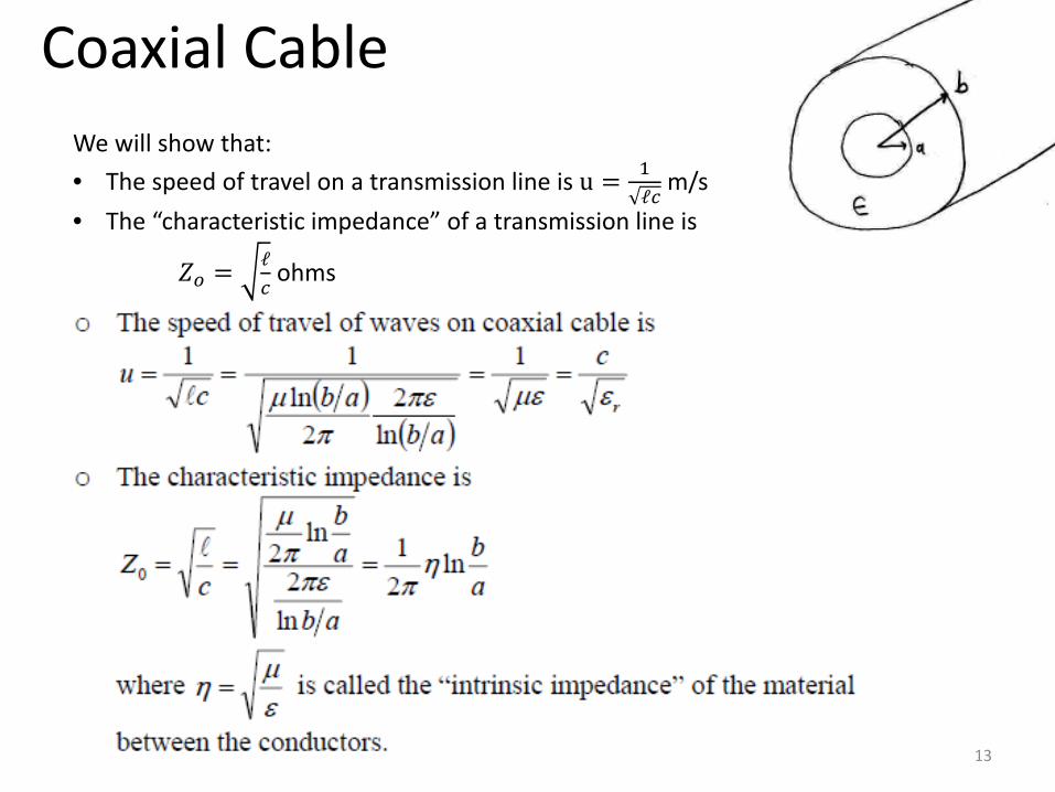
Coaxial CableWe will show that:• The speed of travel on a transmission line is u = 1
ℓ𝑐𝑐m/s
• The “characteristic impedance” of a transmission line is
𝑍𝑍𝑜𝑜 = ℓ𝑐𝑐
ohms
Coaxial Filters: Low Pass Filter
http://www.atlantarf.com/CLPfilter.php
𝑗𝑗𝜔𝜔𝐿𝐿
1𝑗𝑗𝜔𝜔𝜔𝜔
matched
matched
15
Two-conductor transmission lines are also called TEM lines.
“TEM” stands for “transverse electric magnetic”. Both the electric field and the magnetic field vectors lie in the transverse plane, with no axial component.
Hollow tubes such as rectangular waveguide do not support a TEM mode!
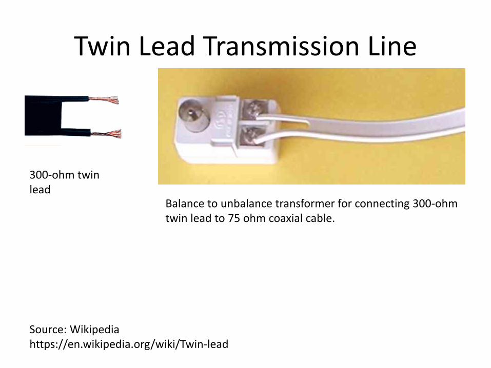
Balance to unbalance transformer for connecting 300-ohm twin lead to 75 ohm coaxial cable.
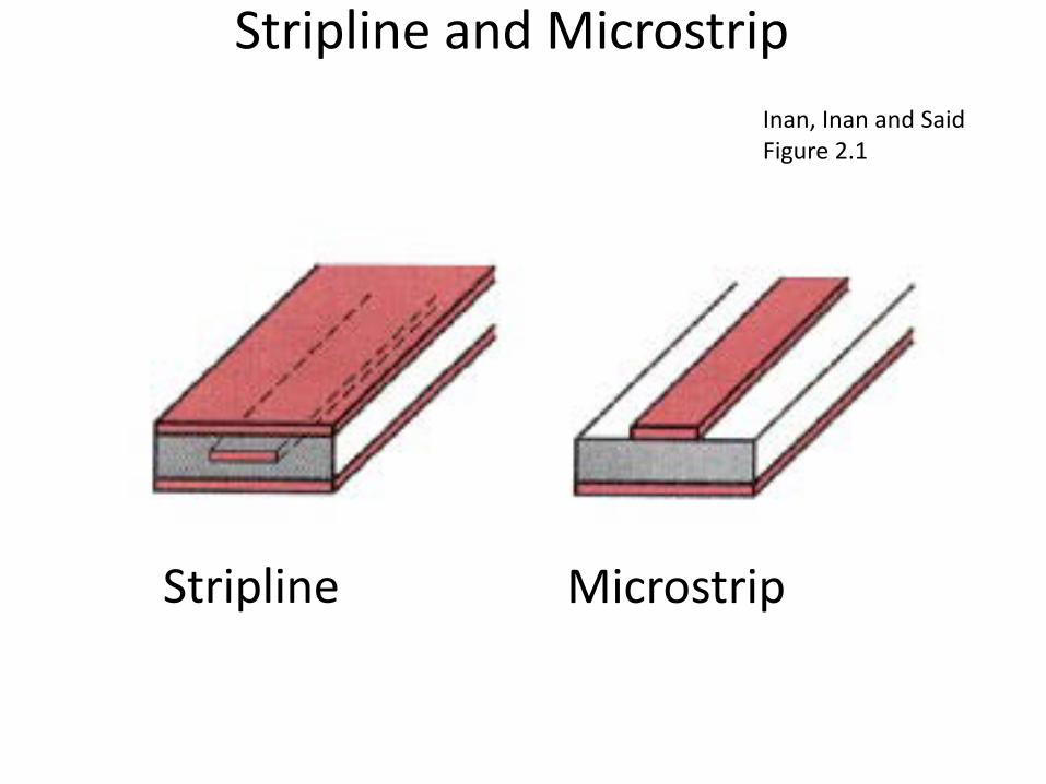
Stripline and MicrostripInan, Inan and Said Figure 2.1
Stripline Microstrip
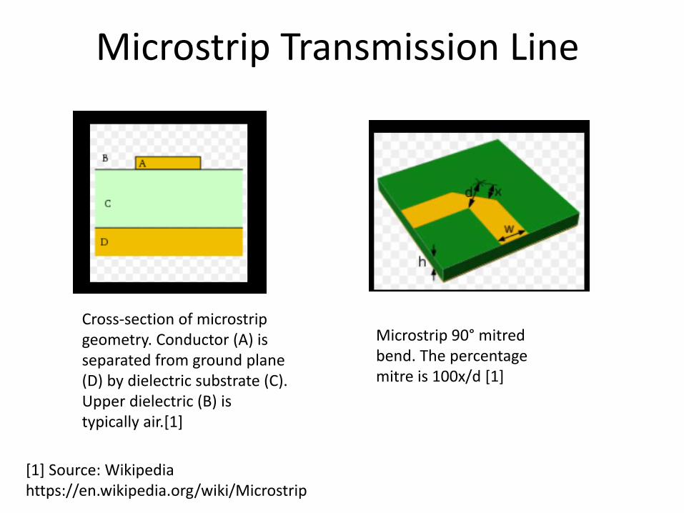
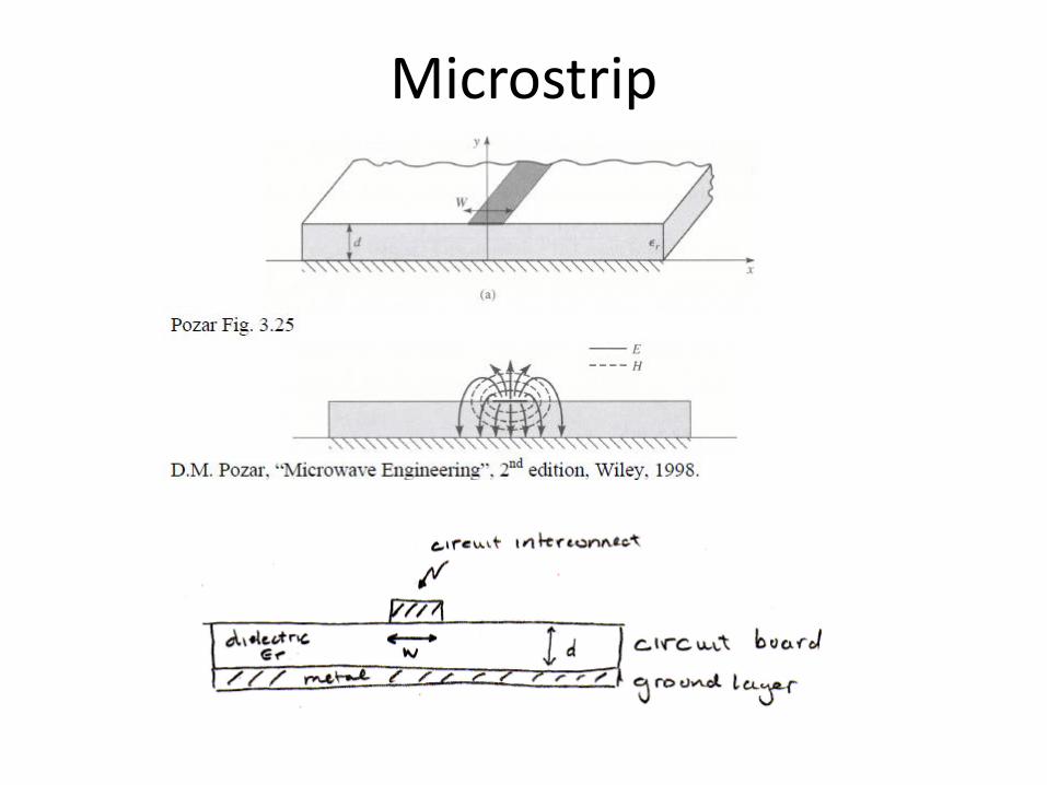
Microstrip Transmission Line
Cross-section of microstripgeometry. Conductor (A) is separated from ground plane (D) by dielectric substrate (C). Upper dielectric (B) is typically air.[1]
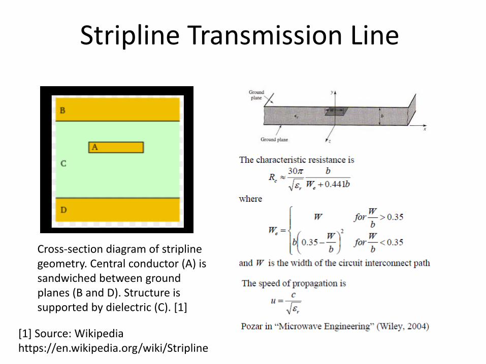
Cross-section diagram of striplinegeometry. Central conductor (A) is sandwiched between ground planes (B and D). Structure is supported by dielectric (C). [1]
40
Transmission Line Circuit
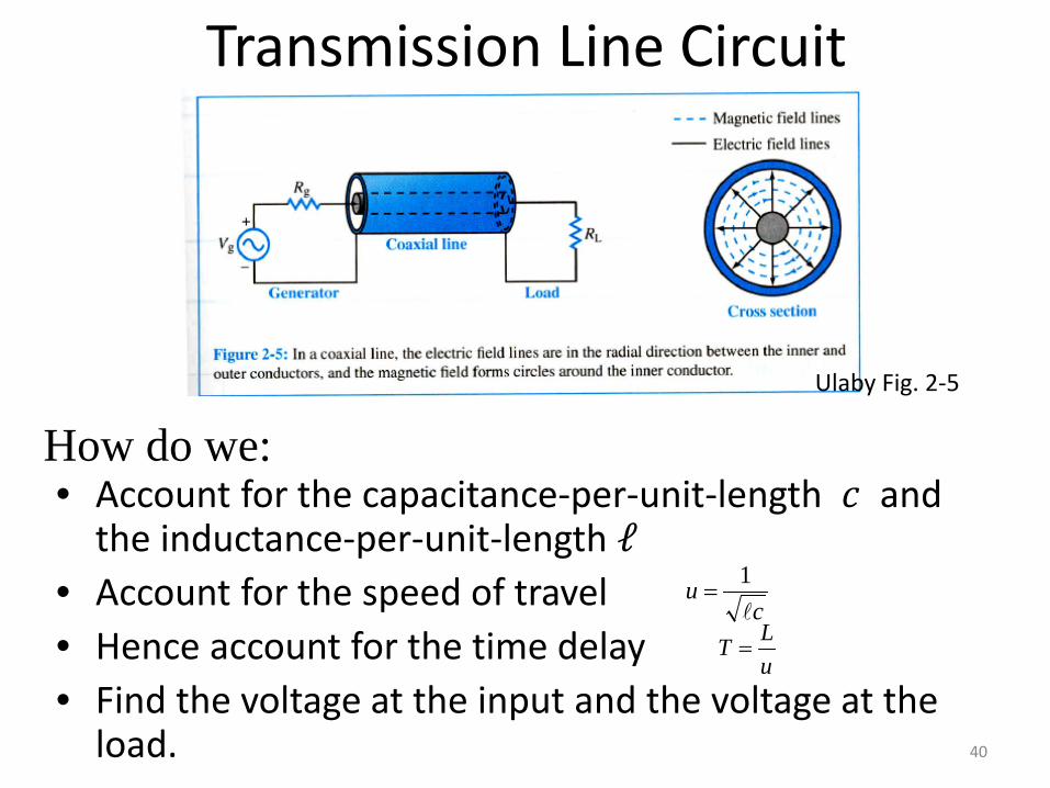
• Account for the capacitance-per-unit-length 𝑐𝑐 and the inductance-per-unit-length ℓ
• Account for the speed of travel• Hence account for the time delay• Find the voltage at the input and the voltage at the
load.
cu
1=
uLT =
Ulaby Fig. 2-5
How do we:
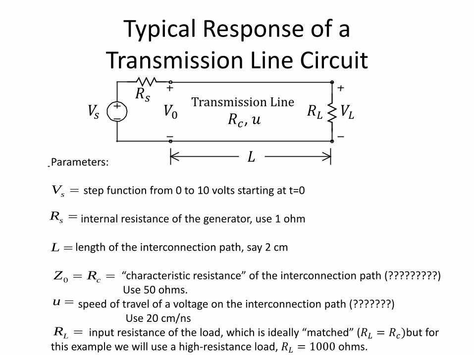
Typical Response of a Transmission Line Circuit
Parameters:
step function from 0 to 10 volts starting at t=0
internal resistance of the generator, use 1 ohm
length of the interconnection path, say 2 cm
“characteristic resistance” of the interconnection path (?????????)Use 50 ohms.
speed of travel of a voltage on the interconnection path (???????) Use 20 cm/ns
input resistance of the load, which is ideally “matched” (𝑅𝑅𝐿𝐿 = 𝑅𝑅𝑐𝑐)but for this example we will use a high-resistance load, 𝑅𝑅𝐿𝐿 = 1000 ohms.
=sV
=sR
=L
== cRZ0
=u
=LR
𝐿𝐿
𝑉𝑉𝐿𝐿𝑅𝑅𝐿𝐿𝑅𝑅𝑠𝑠
𝑉𝑉𝑠𝑠 𝑉𝑉0Transmission Line
𝑅𝑅𝑐𝑐, 𝑢𝑢
Step Response
The slide shows one frame from an animation of the response of the circuit, obtained from the BOUNCE program.
Questions:
• What is the physics of this behavior?• How does it arise from circuit analysis?• How do you solve circuits such as this one?
Time domain?Frequency domain?
• What determines the speed of travel?• What is ‘characteristic resistance’?• How do you design the circuit to avoid this


![ON AN INTEGRATED DYNAMIC …Latin American Journal of Solids and Structures, 2019, 16(2), e164 4/19 where Ω 𝑟𝑟 is the so-called reduced frequency [rad/s], 𝑇𝑇 0 is the](https://static.documents.pub/doc/80x56/5fb0a24e97587227793bb3b3/on-an-integrated-dynamic-latin-american-journal-of-solids-and-structures-2019.jpg)


![How Probable is “Plausible”? - Epstein for Illinois …...2018] How Probable is “Plausible”? 37 𝐸𝐸(𝑃𝑃𝑃𝑃2 𝑃𝑃𝑃𝑃1,𝛹𝛹) < 𝜏𝜏 and 𝛼𝛼](https://static.documents.pub/doc/80x56/5eda1a8db3745412b570c556/how-probable-is-aoeplausiblea-epstein-for-illinois-2018-how-probable-is.jpg)


