ELECTROCHEMISTRY INTRODUCTION Electrochemistry is a branch of chemistry which deals with the behaviour of electrolytes in solution and interconversion of chemical and electrical energies; that is, the study of chemical changes due to the flow of an electric current and production of an electric current due to chemical reaction. Because of the practical importance of electrochemistry such as electroplating, electro extraction of metals, electro refining of metals, electro-production of certain compounds etc., it has become a very interesting field of study for the scientists and technologists. Electrochemical Cells An electrochemical cell consists of two electrodes or metallic conductors, in contact with an electrolyte, an ionic conductor. An electrode and its electrolyte comprise an electrode compartment. The two electrodes may share the same compartment. If the electrolytes are different, the two compartments may be joined by a salt bridge, which is a tube containing a concentrated electrolyte solution in agar jelly that completes the electrical circuits and enables the cell to function. So an electrochemical cell can be defined as a single arrangement of two electrodes in one or two electrolytes which converts chemical energy into electrical energy or electrical energy into chemical energy. Electrochemical cells can be classified into two types: 1. Galvanic Cells 2. Electrolytic Cells Galvanic Cells A galvanic cell is an electrochemical cell that produces electricity as a result of the spontaneous reaction occurring inside it. Galvanic cell generally consists of two electrodes dipped in two electrolyte solutions which are separated by a porous diaphragm or connected through a salt bridge. To illustrate a typical galvanic cell, we can take the example of Daniel cell.
Transcript
ELECTROCHEMISTRY INTRODUCTION Electrochemistry is a branch of chemistry which deals with the behaviour of electrolytes in solution and interconversion of chemical and electrical energies; that is, the study of chemical changes due to the flow of an electric current and production of an electric current due to chemical reaction. Because of the practical importance of electrochemistry such as electroplating, electro extraction of metals, electro refining of metals, electro-production of certain compounds etc., it has become a very interesting field of study for the scientists and technologists. Electrochemical Cells An electrochemical cell consists of two electrodes or metallic conductors, in contact with an electrolyte, an ionic conductor. An electrode and its electrolyte comprise an electrode compartment. The two electrodes may share the same compartment. If the electrolytes are different, the two compartments may be joined by a salt bridge, which is a tube containing a concentrated electrolyte solution in agar jelly that completes the electrical circuits and enables the cell to function. So an electrochemical cell can be defined as a single arrangement of two electrodes in one or two electrolytes which converts chemical energy into electrical energy or electrical energy into chemical energy. Electrochemical cells can be classified into two types:
1. Galvanic Cells 2. Electrolytic Cells
Galvanic Cells A galvanic cell is an electrochemical cell that produces electricity as a result of the spontaneous reaction occurring inside it. Galvanic cell generally consists of two electrodes dipped in two electrolyte solutions which are separated by a porous diaphragm or connected through a salt bridge. To illustrate a typical galvanic cell, we can take the example of Daniel cell.
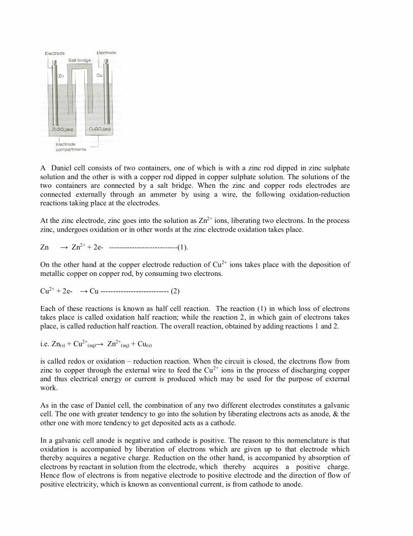
A Daniel cell consists of two containers, one of which is with a zinc rod dipped in zinc sulphate solution and the other is with a copper rod dipped in copper sulphate solution. The solutions of the two containers are connected by a salt bridge. When the zinc and copper rods electrodes are connected externally through an ammeter by using a wire, the following oxidation-reduction reactions taking place at the electrodes. At the zinc electrode, zinc goes into the solution as Zn2+ ions, liberating two electrons. In the process zinc, undergoes oxidation or in other words at the zinc electrode oxidation takes place. Zn → Zn2+ + 2e- ---------------------------(1).
On the other hand at the copper electrode reduction of Cu2+ ions takes place with the deposition of metallic copper on copper rod, by consuming two electrons. Cu2+ + 2e- → Cu --------------------------- (2)
Each of these reactions is known as half cell reaction. The reaction (1) in which loss of electrons takes place is called oxidation half reaction; while the reaction 2, in which gain of electrons takes place, is called reduction half reaction. The overall reaction, obtained by adding reactions 1 and 2. i.e. Zn(s) + Cu2+
(aq)→ Zn2+(aq) + Cu(s)
is called redox or oxidation – reduction reaction. When the circuit is closed, the electrons flow from zinc to copper through the external wire to feed the Cu2+ ions in the process of discharging copper and thus electrical energy or current is produced which may be used for the purpose of external work.
As in the case of Daniel cell, the combination of any two different electrodes constitutes a galvanic cell. The one with greater tendency to go into the solution by liberating electrons acts as anode, & the other one with more tendency to get deposited acts as a cathode.
In a galvanic cell anode is negative and cathode is positive. The reason to this nomenclature is that oxidation is accompanied by liberation of electrons which are given up to that electrode which thereby acquires a negative charge. Reduction on the other hand, is accompanied by absorption of electrons by reactant in solution from the electrode, which thereby acquires a positive charge. Hence flow of electrons is from negative electrode to positive electrode and the direction of flow of positive electricity, which is known as conventional current, is from cathode to anode.
Electrolytic cell An electrolytic cell is an electro –chemical cell in which a non- spontaneous reaction is driven by an external source of current although the cathode is still the site of reduction, it is now the negative electrode whereas the anode, the site of oxidation is positive. The electrolytic cells find wide applications in purification of metals & also in electro deposition of a metal on to the surface of another metal, alloy or any conductor in general, by the process of electrolysis.
Electrolysis involves conversion of electrical energy into chemical energy i.e. chemical changes are brought about by the expense of electrical energy. Since electrolysis is a non spontaneous process, the minimum energy required to carry out such a process is equal to the free energy increase accompanying the change, & this is equal but opposite in sign to the free energy decrease accompanying the reverse spontaneous process. This is true when electrolysis is carried out reversibly. However, in irreversible conditions, the potential to be applied for electrolysis is higher than the reversible emf of the cell. Representation of a galvanic cell According to present conventions, a galvanic cell is represented by keeping in view the following points:
1. Anode is written on the left hand side; while cathode is written on the right hand side. 2. The electrode on the left (i.e. anode) is written by writing the metal (or solid phase) first and
then the electrolyte. The two are separated by a vertical line or a semicolon. The electrolyte may be represented by the formula of the whole compound or by ionic species. Additional information regarding concentration may also be mentioned in bracket. These points will be made clear by following examples of representing anode half-cell as:
Zn│Zn2+ or Zn; Zn2+ or Zn │ ZnSO4 (1M) or Zn; ZnSO4 (1M)
3. The cathode of the cell (at which reduction takes place) is written on the right hand side. In case, the electrolyte is represented first and the metal (or solid phase) thereafter. The two are
separated by a vertical line or a semicolon. A few examples of representing cathode half cell are cited below:
Cu2+│Cu or Cu2+; Cu or Cu2+ (1M); Cu or CuSO4 (1M)/Cu 4. A salt bridge is indicated by two vertical lines, separating the two half-cells. Thus, applying above considerations to Daniel cell, we may represent it as: Zn │ ZnSO4 (1M)║ CuSO4(1M)/Cu
LIQUID JUNCTION POTENTIAL In a cell with two different electrolyte solutions in contact through a diaphragm, as in the Daniel cell, there is an additional source of potential difference across the interface of the two electrolytes. This potential is called the liquid junction potential, Ej.
In a Daniel cell, let the concentrations of ZnSO4(aq) and CuSO4(aq) be the same. As a result, concentrations of SO4
2- ions are equal in the two solutions and hence SO42-ions do not diffuse across
the junction. But Cu2+ ions diffuse into ZnSO4 (aq) and Zn2+ ions diffuse into CuSO4 (aq) because Cu2+ ions are slightly more mobile than Zn2+ ions. This produces a small excess positive charge on ZnSO4 (aq) side of the junction and equal negative charge on the CuSO4(aq) side. Negative charge speeds up the diffusion of Zn2+ ions into CuSO4 (aq) side and positive charge retards the diffusion of Cu2+ ions into ZnSO4 (aq) side. Charge built up occurs until a steady state reached at which Cu2+ and Zn2+ ions diffuse at equal rates. The liquid junction potential is the difference between the electric potential developed in the two solutions across their interface
i.e. Ej = Ø soln, R - Ø soln,L
Ø soln. R is the electric potential of the electrolyte solution on the right hand side half – cell in the cell scheme. Ø soln. L is the electric potential of the electrolyte solution on the left hand side half-cell in the cell scheme.
Another example of a junction potential is that between different concentrations of hydrochloric acid. At the junction, the mobile H+ ions diffuse into the more dilute solution. The bulkier Cl- ions follow, but initially do so more slowly, which results in a potential difference at the junction. The potential then settles down to a value such that, after that brief initial period the ions diffuse at the same rates. Electrolyte concentration cells always have a liquid junction, electrode concentration cells do not.
The junction potential contributes to the cell emf. It adds up to the emf when it operates with the emf and it reduces the emf when it operates opposite to the emf. Generally, junction potentials are of the order of magnitude 10 to 30 mV. Theoretical evaluation of junction potential is usually difficult. SALT BRIDGE
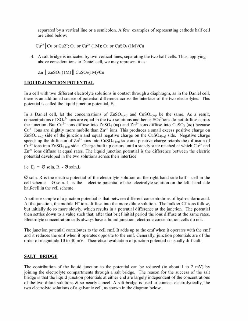
The contribution of the liquid junction to the potential can be reduced (to about 1 to 2 mV) by joining the electrolyte compartments through a salt bridge. The reason for the success of the salt bridge is that the liquid junction potentials at either end are largely independent of the concentrations of the two dilute solutions & so nearly cancel. A salt bridge is used to connect electrolytically, the two electrolyte solutions of a galvanic cell, as shown in the diagram below.
The salt bridge consists of a saturated solution of a salt such as KCl or NH4NO3, whose ions have almost same migration velocities. The positive and negative ions of the salt in the salt bridge migrate with equal speed into cathode and anode compartments respectively, thereby avoiding liquid junction potential.
The salt bridge is prepared by dissolving a little of agar agar in a hot solution of KCl and filling in a U-tube. On cooling, the agar forms a jell with KCl solution in it. The salt bridge is also prepared by filling a U-tube with saturated solution of KCl and plugging the two ends with a porous material.
A salt bridge has the following functions:
1. It provides electrolytic contact between the two electrolyte solutions of a cell 2. It avoids or at least reduces junction potential in galvanic cells containing two electrolyte solutions in contact.
ELECTROMOTIVE FORCE OF THE CELL
Current can not flow from one point to another unless there is a potential difference between the two points. The difference of potential, which causes a current to flow from the electrode of higher potential to one of lower potential is called the “electromotive force (e.m.f.) of the cell “or the “cell potential” and is expressed in volts V. The emf of a cell is denoted by E cell .Mathematically,
Ecell = Ecathode- Eanode The E Cell depends on the nature of the electrode, temperature and concentration of the electrolyte solutions. To facilitate comparison of different galvanic cells, their standard emf, denoted by E0 cell is used. Standard emf of a cell is defined as the emf of a cell when the reactants & products of the cell reaction are at unit concentration or unit activity, at 298 K and at 1 atmospheric pressure.
The emf of a cell represents the driving force of a cell reaction. As represented by the thermodynamic relation,
∆G = -nFE
Where ∆G is the free energy change accompanying a cell reaction, n is the number of electron transfer during the cell reaction, and F is the Faraday constant, F = eNA, the magnitude of the charge
per mole of electrons. Hence the above equation is the key connection between the electrical measurements on the one hand and thermodynamic properties on the other.
The cell reaction is spontaneous or feasible when ∆G is negative. ∆G can be negative only if emf of the cell is positive, because, the other two factors, n & F are always positive. Thus emf of a galvanic cell is always positive. The positive emf value indicates the spontaneity of cell reaction in the given direction.
When the cell potential is large, a given number of electrons traveling between the electrodes can do a large amount of electrical work. When the cell potential is small, the same number of electrons can do only a small amount of work. A cell in which the overall reaction is at equilibrium can do no work, and then the cell potential is zero.
MEASUREMENT OF EMF OF A CELL
The emf cannot be measured accurately by connecting directly a voltmeter between the two electrodes, because during such a measurement, a part of the cell current is drawn, thereby causing a change in the emf, due to the formation of reaction products at the electrodes and change in the concentration of the electrolyte around the electrodes. Consequently, such a measurement would indicate a potential difference less than the actual emf of the cell. For precise emf measurements potentiometers are used, which require extremely small current at balance point.
The potentiometric measurement of emf of a cell works based on Poggendorff’s compensation principle. In this method, emf of a test cell is opposed by the impressed emf from an external source of emf, and the measurement is made when there is no net flow of current in the circuit.
A simplified diagram of potentiometer is shown below.
The two terminals of a storage battery(E) which has a constant and higher emf than the test cell, is connected to two ends of a long uniform wire AB of high resistance. The positive terminal of the test cell is connected to the end A, to which the positive terminal of E is connected & the negative terminal is connected to a sliding contact D through a galvanometer (G). The sliding contact is moved along the wire AB until the null point is reached, which is indicated by no current flow in the galvanometer. The position of null point is noted & the distance AD is measured. The emf of the cell Ex is proportional to the length AD.
Ex α AD
Then the test cell Ex is replaced by a standard cell Es, whose emf, is known the position of the sliding contact is readjusted by moving it over AB, as before, till null point D1 is reached again. The length AD1 is measured. The emf of the standard cell Es is proportional to the length AD1.
Es α AD1
Ex ═ AD Es AD1
Ex = AD x Es AD1 Thus the emf of the test cell is calculated by knowing the emf of the standard cell. STANDARD WESTON CADMIUM CELL
A standard cell is one which is capable of giving constant and reproducible emf. It has a negligible temperature – coefficient of the emf. In other words, standard cell is a source of unvarying potential. These conditions are satisfied in Weston standard cell. So Weston standard cell is the most commonly used standard cell in the potentiometric measurement of emf of a cell.
Construction: It consists of an H-shaped glass vessel, with the lower ends of both arms closed, having platinum wire scaled into the bottom of the each arm. The positive electrode contains mercury over which a paste of mercurous sulphate (Hg2SO4) and mercury is placed. The negative electrode consists of an amalgam of Cd and Hg, containing about 12-15% Cd by weight. Over both electrodes are sprinkled some crystals of solid CdSO4. 8/3 H2O as shown in the figure. The remaining part of the cell is filled with a saturated solution of cadmium sulphate. The cupper ends of the tube are closed with corks and sealing –wax.
Sealed wax
Cork Saturated solution of
CdSO4.8/3H2OCdSO4.8/3H2O
crystals
Cd-Hg
12-14% Cd
Paste of Hg2SO4
Mercury, Hg
Working: When the cell operates, the following reactions occur at the two electrodes.
Cd (s) → Cd2+ + 2e- (At negative electrode) Hg2SO4(s) + 2e- → 2 Hg (l) + SO4
2-(aq) (At positive electrode)
The purpose of solid crystals of CdSO4 8/3 H2O is to keep the electrolyte saturated at all temperatures. The potential of this cell is 1.0183 volts at 20o C and 1.0181 volts at 25oC and it varies slightly (about -0.09046 volt per degree centigrade). The cell works for many years at a stretch, without any voltage changes. SINGLE ELECTRODE POTENTIAL
A metal (M) consists of metal ions (Mn+) with the valence electrons that bind them together. Now, if a metal is in contact with a solution of its own salt, (the positive ions in the metal come into equilibrium with those in the solution leaving behind an equivalent number of electrons on the metal.) two types of reactions are possible. The metal shows the tendency to go into the solution as metal ion by losing electrons. eg. In case of Zn in ZnSO4 solution acquires a negative charge.
M → Mn+ + ne - (1) Conversely, if the metal ions in the solution show the tendency to get deposited as metal atoms, then metal acquires a positive charge. Eg: in case of Cu in CuSO4 solution
Mn++ ne- → M (2)
The rate of this reaction depends on, (i) the nature of the metal (ii) the temperature (iii) the concentration of metal ions in solution.
When a metal is placed in the solution of its own salt, the chemical reaction (1) or (2), as the case may be, takes place and ultimately a dynamic equilibrium is established, because negative or positive charge developed on the metal attracts the positively or negatively charged free ions in the solution. Due to this attraction, the positive or negative ions remain quite close to the metal. Thus, a short of layer of positive ions or negative ions as in the figure is formed all around the metal. This layer is called Helmholtz electrical double layer. A difference of potential is consequently, set up between the metal and the solution. This potential difference will persist as long as the charge is allowed to remain on the metal; and this will prevent any further passing of the positive ions from or to the metal. At equilibrium the potential difference between the metal & solution becomes a constant value. The equilibrium potential difference so established is called the “electrode potential” of the metal. This, electrode potential of a metal is the measure of tendency of a metallic electrode to lose or gain electrons, when it is in contact with a solution of its own salt of unit molar concentration at 25oC. Consequently, the tendency of an electrode to lose electrons is a direct measure of its tendency to get oxidized & this tendency, is called oxidation potential. Similarly, the tendency of an electrode to gain electrons is a direct measure of its tendency to get reduced and this tendency is known as reduction potential. It is quite obvious that the value of reduction potential is negative of its oxidation potential and vice-versa. Thus, if the oxidation potential of an electrode is +X volt, then its reduction potential will have a value of –X volt. MEASUREMENT OF ELECTRODE POTENTIAL
It is impossible to know the absolute value of a single electrode potential (i.e, potential difference between an electrode and the surrounding solution of its own salt). We can only measure the difference in potential between two electrodes potentiometrically, by combining them to form a complete cell. In other words, we can only determine the relative value of electrode potential, if we can fix arbitrarily the potential of any one electrode. For this purpose, the potential of a standard hydrogen electrode(SHE) or normal hydrogen electrode (NHE) (i.e., a platinum electrode in contact with 1 M H+ ion concentration and hydrogen gas at atmospheric pressure is constantly bubbled over it) has been arbitrarily fixed at zero; and all other electrode potentials are expressed in comparison with this value. Therefore, single electrode potentials of electrodes are referred to as potentials on the hydrogen scale.
According to latest accepted conventions, all single electrode potential values represent reduction tendency of electrodes. Higher the value of electrode potential, higher is the tendency of the electrode to act as reduction electrode. When two electrodes are combined to form a cell, the one with lower electrode potential, with fewer tendencies to undergo reduction acts as cathode. For example, in Daniel cell, zinc with lower electrode potential acts as anode and copper with higher electrode potential acts as cathode. Similarly, when copper electrode is combined with a silver electrode, copper with lower electrode potential acts as anode & silver with higher electrode potential acts as cathode.
Standard electrode potential:
Standard electrode potential is the electrode potential when the electrode is in contact with a solution of unit concentration at 298 K. If the electrode involves a gas, then the gas is at 1 atmospheric pressure. It is denoted by Eo. When elements are arranged in increasing order (downwards) of their standard electrode potential, a series called electrochemical series is obtained. Table 1.Standard electrode potentials (reduction) at 25˚C.
Metal ion Potential in Volts Li+ + e- → Li (Base) K+ + e- → K Ca2+ + 2e- → Ca Na+ + e- → Na Mg2+ + 2e- → Mg Al3+ + 3e- → Al Zn2+ + 2e- → Zn Cr3+ + 3e- → Cr Fe2+ + 2e- → Fe Ni2+ + 2e- → Ni Sn2+ + 2e- → Sn Pb2+ + 2e- → Pb Fe3+ + 3e- → Fe H+ + e- → ½ H2 Cu2+ + 2e- → Cu Ag+ + e- → Ag Pt4+ + 4e- → Pt Au+ + e- → Au ½ F2 + e- → F- (Noble)
Sign of electrode potential: The electrode potential of an electrode is positive, if the electrode reaction is reduction when coupled with the standard hydrogen electrode and is negative if the electrode reaction is oxidation when coupled with standard hydrogen electrode. For example, when copper electrode is combined with standard hydrogen electrode, copper electrode acts as cathode and undergoes reduction hydrogen electrode acts as anode. Hence electrode potential of copper is assigned a positive sign. Its standard electrode potential is 0.34 V.
H2(g) → 2H+ +2e- (oxidation) Cu2+ +2e- → Cu (reduction)
When zinc is coupled with S.H.E., zinc electrode acts as anode and hydrogen electrode acts as cathode. Hence, electrode potential of zinc is negative. The standard electrode potential of zinc electrode is -0.74 V. Zn → Zn2+ +2e- 2H+ + 2e -→ H 2
NERNST EQUATION
In 1889, Nernst derived a quantitative relationship between electrode potential and concentration of the electrolyte species. This expression is known as Nernst equation. Consider a general redox reaction: Mn+
(aq) + ne- <═> M(s)
E = Eo + 2.303RT/nF log [Mn+] At 298K, when the values of R.T and F are substituted, the equation reduces to,
E = Eo + 0.0591 log [Mn+] n
This expression is known as Nernst equation for electrode potential at 298K. From these equations, it is clear that,
i) If concentration of solution (Mn+) is increased, the electrode potential increases and vice versa.
ii) If temperature is increased, the electrode potential increases and vice versa. The Nernst equation can also be applied for the calculation of emf of a cell. Consider the cell reaction aA+ bB <=======> cC +dD
The Nernst equation for the emf of the cell is
Ecell = Eo
cell – 0.0591 log [C]c [D]d /[A]a [B]b at 298 K. n
Where n is the number of electrons transferred during the cell reaction and Eo
cell is the standard emf of the cell.
Nernst equation derivation:
• Consider a general redox reaction:
Mn+ (aq) + ne- → M (s) ---- (1) We know that, ΔG = -nFE ---- (2) ΔGo = -nFEo ---- (3) (ΔG →Free energy change,n→ no of electron transfer during reaction,F→ faraday)
Free energy change accompanying the process is given by well known thermodynamic eqn. (van’t Hoff reaction isotherm)
oG G RT ln K
R→Gas constant, T→Absolute temp K stands for reaction quotient of the activities of the products, aM
and reactants, aMn+ at any given stage of reaction
on
[M]G G RT ln [M ]
on
[M]nFE nFE RT ln [M ]
on
RT 1E E ln nF [M ]
(concentration of metal, M, is unity)
on
RT 1E E 2.303 log nF [M ]
R= is the universal gas constant (8.314 J mol−1 K−1), F= 9.6485 x 10⁴ C mol−1.
At T 298K,
on
0.0592 1E E log n [M ]
o n0.0592E E log [M ]n
This expression is known as Nernst’s equation for electrode potential at 298K. CALOMEL (MERCURY/MERCUROUS CHLORIDE ELECTRODE The calomel electrode, a mercury mercurous chloride electrode develops 242 mV vs. the standard hydrogen when the KCl solution is saturated. It has been found that the potential of the calomel electrode, on the hydrogen scale varies with the concentration of the potassium chloride solution used. The concentration of KCl solution used is either decinormal, normal or saturated. Correspondingly the electrode is known as decinormal, normal or saturated calomel electrode respectively. Calomel electrode is capable of producing constant reproducible electrode potential. So it is commonly used in pH measurement cyclic voltammetry and general aqueous electrochemistry.
Construction and Working:
It consists of a tube, in the bottom of which is a layer of mercury, over which is placed a paste of Hg + Hg2Cl2. The remaining portion of cell is filled with a solution of normal or decinormal or saturated solution of KCl. A platinum wire, dipping into the mercury layer is used for making electrical contact with a salt bridge. The electrode can be represented as Hg(l)/Hg2Cl2 (s) / Cl- The calomel electrode can act as anode or cathode depending on the nature of other electrode of the cell. When it acts anode, the electrode reaction is
2 Hg + 2Cl- → Hg2Cl2 + 2e- When it acts as cathode, the electrode reaction is, Hg2
2+ + 2e-→ 2 Hg Hg2Cl2 → Hg2
2+ + 2Cl- _____________________ Hg2Cl2 + 2e- → 2Hg (l) + 2 Cl- The net reversible electrode reaction is, Hg2Cl2(s) + 2e- <════> 2 Hg (l) + 2 Cl- Electrode potential is given by E = Eo – 2.303 RT log [Cl-)2
2F
= Eo - 0.0591 log [Cl-] at 298 K The electrode potential is decided by the concentration of chloride ions & the electrode is reversible with chloride ions at 298K, as follows. 0.1N KCl electrode (0.334V)
Uses: i) It is used as a secondary reference electrode in the measurement of single electrode potential. It is the most commonly used reference electrode in all potentiometric determinations. For example: The test electrode, Zn(s) /Zn2+
(aq) is coupled with a saturated calomel electrode. Zn(s) / Zn2+ (aq) ││ Cl- (saturated soln) /Hg2Cl2(s) / Hg (l) The emf of the so formed cell is determined experimentally by potentiometric method. Then E cell = E cathode – E anode
= 0.2422 – Ezn OR Ezn = 0.2422 – E cell
Advantages 1. It has similar stability to silver/silver chloride and a better thermal hysterisis. 2. It is less prone to contamination because the mercury/ mercurous chloride interface is protected inside a tube not in direct contact with the electrolyte. 3. Freshly prepared calomel electrode could show a potential different from the standard value by 2-5 mV. It shows the reproducibility of a calomel electrode is much better than a silver/ silver chloride electrode. Hence, it is recommended to use as a reference electrode widely in the pH measurements, cyclic voltammetry & general aqueous electrochemistry. Disadvantages 1. Calomel electrodes should not be used above 50oC because the mercurous chloride breaks down, yielding unstable readings. 2. Calomel has fallen into disfavor because of its toxicity. Actually, the calomel reference electrode is not toxic unless a glass container is broken.
GLASS ELECTRODE Construction:
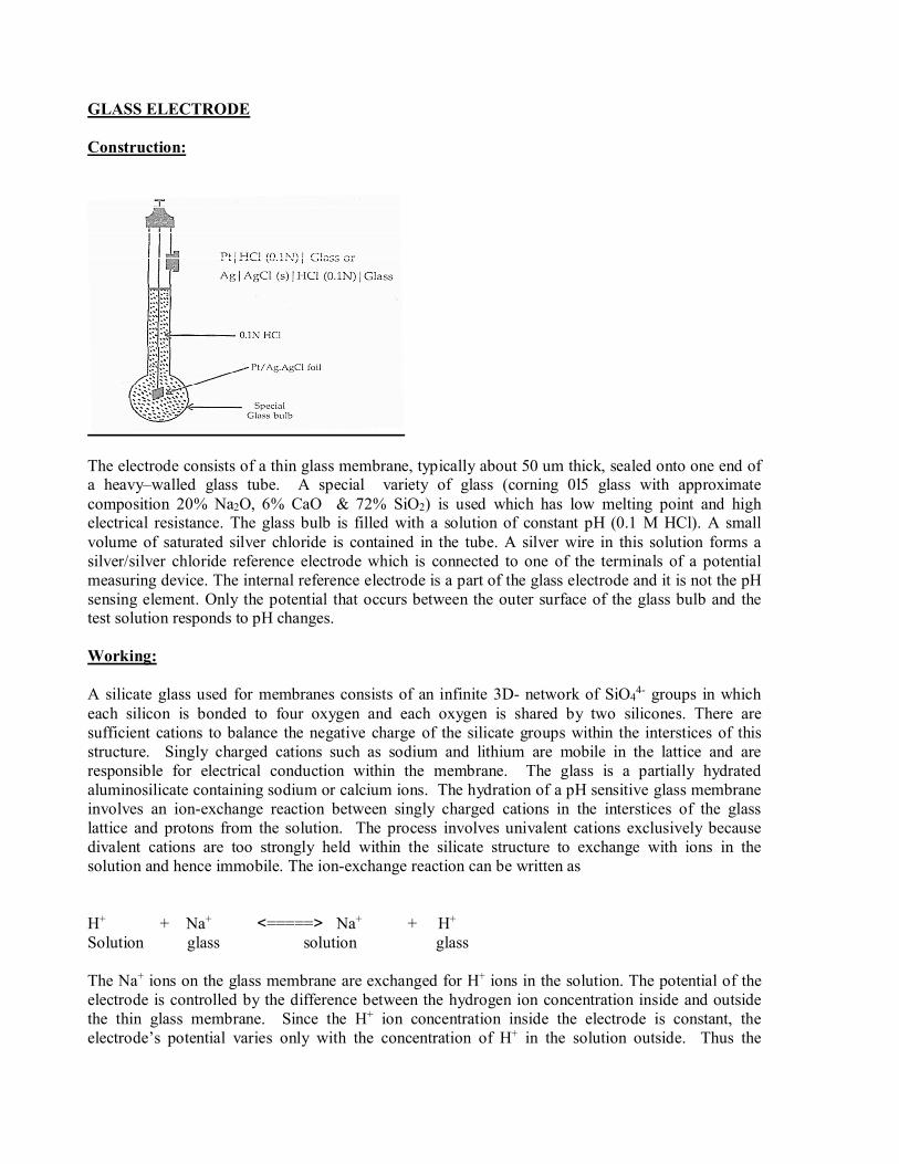
The electrode consists of a thin glass membrane, typically about 50 um thick, sealed onto one end of a heavy–walled glass tube. A special variety of glass (corning 0l5 glass with approximate composition 20% Na2O, 6% CaO & 72% SiO2) is used which has low melting point and high electrical resistance. The glass bulb is filled with a solution of constant pH (0.1 M HCl). A small volume of saturated silver chloride is contained in the tube. A silver wire in this solution forms a silver/silver chloride reference electrode which is connected to one of the terminals of a potential measuring device. The internal reference electrode is a part of the glass electrode and it is not the pH sensing element. Only the potential that occurs between the outer surface of the glass bulb and the test solution responds to pH changes. Working: A silicate glass used for membranes consists of an infinite 3D- network of SiO4
4- groups in which each silicon is bonded to four oxygen and each oxygen is shared by two silicones. There are sufficient cations to balance the negative charge of the silicate groups within the interstices of this structure. Singly charged cations such as sodium and lithium are mobile in the lattice and are responsible for electrical conduction within the membrane. The glass is a partially hydrated aluminosilicate containing sodium or calcium ions. The hydration of a pH sensitive glass membrane involves an ion-exchange reaction between singly charged cations in the interstices of the glass lattice and protons from the solution. The process involves univalent cations exclusively because divalent cations are too strongly held within the silicate structure to exchange with ions in the solution and hence immobile. The ion-exchange reaction can be written as H+ + Na+ <=====> Na+ + H+ Solution glass solution glass The Na+ ions on the glass membrane are exchanged for H+ ions in the solution. The potential of the electrode is controlled by the difference between the hydrogen ion concentration inside and outside the thin glass membrane. Since the H+ ion concentration inside the electrode is constant, the electrode’s potential varies only with the concentration of H+ in the solution outside. Thus the
potential arises from the difference in positions of ion-exchange equilibrium on each of the two surfaces. The surface exposed to the solution having the higher H+ concentration becomes positive with respect to the other surface. This charge difference or potential serves as the analytical parameter when the pH of the solution on one side of the membrane is held constant. Evidently the selectivity of glass electrodes is related both to the ability of the various monovalent cations to penetrate into the glass membrane and to the degree of attraction of the cations to the negative sites within the glass. Electrode Potential of glass electrode The overall potential of the glass electrode has three components. 1) The boundary potential Eb, which varies with the pH of the analyte solution. It is made up of two potentials, E1 & E2 which develop at the two surface of the glass membrane i.e. the potential developed at the inner glass surface & the potential developed at the outer glass surface. Eb = E1-E2 _______________________ (1) Where Eb is the boundary potential E1 = potential developed at the interface between the exterior of the glass and the analyte solution E2 = Potential developed at the interface between the internal solution and the interior of the glass. The boundary potential is related to the concentration of hydrogen ion in each of the solution by the Nernst-like equation. Eb = E1 – E2 = 0.0592 log Cl / C2 _________________ (2) Where C1 = concentration of the analyte solution C2 = concentration of the internal solution For a glass pH electrode the hydrogen ion concentration of the internal solution is held constant. So eqn. (2) Simplifies to Eb = K + 0.0592 log C1 __________________(3)
K = - 0.0592 log C 2
The boundary potential is then a measure of 1) the hydrogen ion concentration of the external solution. 2) The potential of the internal Ag/AgCl reference electrode. E Ag/AgCl. 3) A small unpredictable contribution called the asymmetry potential, E asym. The sources of the symmetry potential include the following. (i) Differing conditions of strain in the two glass surfaces during manufacture (ii) Mechanical abrasion on the on the outer surface during use (iii) Chemical etching of the outer surface during use. The asymmetry potential changes slowly with time. The glass electrode potential can be written in the equation form as EG = Eb + EAg/ AgCl + E asym __________________ (4)
Substitution of eqn – (3) for Eb, gives EG = K+0.0592 log C1 + EAg/AgCl + E asym = K – 0.0592 log pH + E Ag/AgCl + E asym ___(5) EG = Eo
G – 0.0592PpH __________________(6) where Eo
G = K + EAg/AgCl + E asym. a combination of three constant terms = constant To measure the hydrogen ion concentration of the test solution, the glass electrode (indicator electrode (indicator electrode) must be combined with an external reference electrode, which is required for all kinds of ion-selective electrode determinations. The cell potential is measured with a pH meter, a voltage - measuring device that electronically converts E cell to pH and displays the result in pH units.
Applications: The glass electrode has an emf that changes with hydrogen ion concentration, i.e the glass electrode is the most important indicator electrode for hydrogen ion. It is used for the measurement of pH under many conditions and normally calomel electrode is used as reference electrode to complete the cell. Cell: SCE │Test solution ║ GE E cell = E glass – E calomel where E glass = the E.P. of glass electrode. E calomel = the E.P. of the SCE E cell = Eo
G – 0.0592 pH – 0.2444 The Eo
G value of a glass electrode can be determined by dipping the glass electrode in a solution of known pH. Typical fields are the clinical & food analysis, environmental monitoring (industrial waste acidity of rain) and process control (fermentation, boiler water, galvanization & precipitation) Advantages: 1. It can be used without interference in solutions containing strong oxidants, strong reductants, proteins, viscous fluids and gases as the glass is chemically robust. 2. It can be used for solutions having pH values 2 to 10. With some special glass (by incorporation of Al2O3 or B2O3) measurements can be extended to pH values up to 12. 3. It is immune to poisoning and is simple to operate. 4. The equilibrium is reached quickly & the response is rapid. 5. It can be used for very small quantities of the solutions. Small electrodes can be used for pH measurement in one drop of solution in a tooth cavity or in the sweat of the skin (micro determinations using microelectrodes)
6. If recently calibrated, the glass electrode gives an accurate response. 7. The glass electrode is much more convenient to handle than the inconvenient hydrogen gas electrode. 8.Glass electrodes which are selective for Li+, Na+, Cs+, Ag+ and NH4
+ ions are commercially available and these special electrodes are useful for measuring the above ions.
Disadvantages: 1. The bulb of this electrode is very fragile and has to be used with great care. The sensitive tip is easily scratched and ruined. 2. The alkaline error arises when a glass electrode is employed to measure the pH of solutions having pH values in the 10-12 range or greater. In the presence of alkali ions, the glass surface becomes responsive to both hydrogen and alkali ions. Low pH values arise as a consequence and thus the glass pH electrode gives erroneous results in highly alkaline solutions. 3. The acid error results in highly acidic solutions (pH less than zero) Measured pH values are high. 4. Dehydration of the working surface may cause erratic electrode performance. It is crucial that the pH electrode be sufficiently hydrated before being used. When not in use, the electrode should be stored in an aqueous solution because once it is dehydrated; several hours are required to rehydrate it fully. 5. As the glass membrane has a very high electrical resistance (50 to 500 MΩ), the ordinary potentiometer cannot be used for measurement of the potential of the glass electrode. Thus special electronic potentiometers are used which require practically no current for their operation. 6. Standardization has to be carried out frequently because asymmetry potential changes gradually with time. Because of an asymmetry potential, not all glass electrodes in a particular assembly have the same value of Eo
G . For this reason, it is best to determine EoG for each electrode before use. Any
asymmetry potential is incorporated into EoG of the electrode and errors are avoided by recalibration
procedure. 7. The commercial version is moderately expensive. 8. To some extent, the constant Eo
G is a function of the area of glass in contact with the acid analyte. For this reason, no two glass electrodes will have the same value of Eo
G. Note that EoG depends on a
particular glass electrode used & it is not a universal constant.
References: 1. ‘Physical chemistry. Peter Atkins & Julio De Paula, Oxford University Press, 2009.
2. Engineering Chemistry, P.C.Jain & M. Jain, Dhanpat Rai Publishing Company, Edn.15, 2005.