1 Unit Configuration Examples Z axis XYZ axes YZ axes Y axis X axis ∗ Motors and drivers must be procured by the customer. X, Y and Z axes are each shipped alone as individual units. Unit configuration must be arranged by the customer. C-E02-15B Electric Actuator Triple Axis P&P Unit Space saving and modularization Wide variety of combinations to satisfy users needs (Ball screw/Motor) Suitable for high-frequency operation
Transcript
1
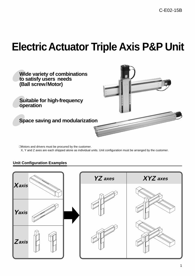
Unit Configuration Examples
Zaxis
XYZ axesYZ axes
Yaxis
Xaxis
∗ Motors and drivers must be procured by the customer.X, Y and Z axes are each shipped alone as individual units. Unit configuration must be arranged by the customer.
C-E02-15B
Electric Actuator Triple Axis P&P Unit
Space saving and modularization
Wide variety of combinations to satisfy users needs (Ball screw/Motor)
Suitable for high-frequency operation
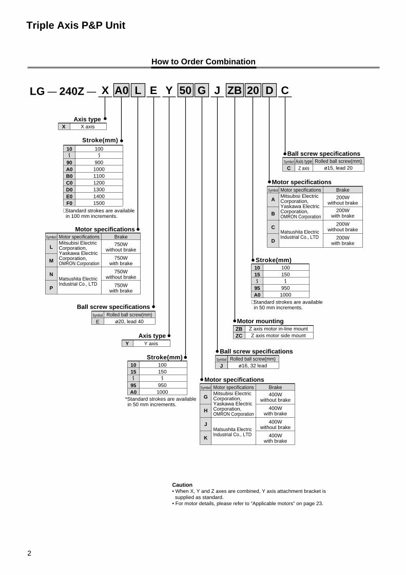
LG — 240Z — A0 50 20X
Motor mountingZBZC
Z axis motor in-line mountZ axis motor side mount
L E G J ZB D C
Stroke(mm)
Motor specifications
Axis type
Axis type
Ball screw specificationsSymbol
ERolled ball screw(mm)
ø20, lead 40
Ball screw specificationsSymbol
CAxis type
Z axisRolled ball screw(mm)
ø15, lead 20
Ball screw specificationsSymbol
JRolled ball screw(mm)
ø16, 32 lead
10
90A0B0C0D0E0F0
100
900100011001200130014001500
Motor specificationsMitsubisi Electric Corporation,Yaskawa Electric Corporation,OMRON Corporation
Matsushita Electric Industrial Co., LTD
Brake
750Wwithout brake
750Wwith brake
750Wwithout brake
750Wwith brake
Symbol
L
M
N
P
Motor specifications
Motor specifications
How to Order Combination
Y
Y Y axis
X X axis
Stroke(mm)1015
95A0
100150
9501000
Stroke(mm)1015
95A0
100150
9501000
Caution• When X, Y and Z axes are combined, Y axis attachment bracket is supplied as standard.• For motor details, please refer to “Applicable motors” on page 23.
Triple Axis P&P Unit
∗ Standard strokes are available in 100 mm increments.
*Standard strokes are available in 50 mm increments.
∗ Standard strokes are available in 50 mm increments.
Motor specificationsMitsubisi Electric Corporation,Yaskawa Electric Corporation,OMRON Corporation
Matsushita Electric Industrial Co., LTD
Brake
200Wwithout brake
200Wwith brake
200Wwithout brake
200Wwith brake
Symbol
A
B
C
D
Motor specificationsMitsubisi Electric Corporation,Yaskawa Electric Corporation,OMRON Corporation
Matsushita Electric Industrial Co., LTD
Brake400W
without brake
400Wwith brake
400Wwithout brake
400Wwith brake
Symbol
G
H
J
K
2
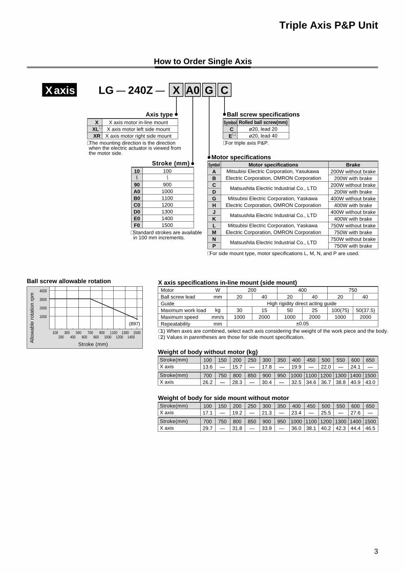
LG — 240Z — A0X G C
Stroke (mm)Motor specifications
Ball screw allowable rotation
Ball screw specifications Axis typeSymbol
CE∗
Rolled ball screw(mm)ø20, lead 20ø20, lead 40
Weight of body without motor (kg)10013.6
150—
20015.7
250—
30017.8
350—
40019.9
450—
50022.0
550—
60024.1
650—
Stroke(mm)X axis
70026.2
750—
80028.3
850—
90030.4
950—
100032.5
110034.6
120036.7
130038.8
140040.9
150043.0
Stroke(mm)X axis
Weight of body for side mount without motor10017.1
150—
20019.2
250—
30021.3
350—
40023.4
450—
50025.5
550—
60027.6
650—
Stroke(mm)X axis
70029.7
750—
80031.8
850—
90033.9
950—
100036.0
110038.1
120040.2
130042.3
140044.4
150046.5
Stroke(mm)X axis
10
90A0B0C0D0E0F0
100
900100011001200130014001500
How to Order Single Axis
XXL∗
XR
X axis motor in-line mountX axis motor left side mount
X axis motor right side mount
∗ 1) When axes are combined, select each axis considering the weight of the work piece and the body.∗ 2) Values in parentheses are those for side mount specification.
Xaxis
X axis specifications in-line mount (side mount)MotorBall screw leadGuideMaximum work loadMaximum speedRepeatability
Wmm
kgmm/smm
20020 40
301000
152000
400
High rigidity direct acting guide
±0.05
20 40
501000
252000
75020 40
100(75)1000
50(37.5)2000
∗ Standard strokes are available in 100 mm increments.
∗ The mounting direction is the direction when the electric actuator is viewed from the motor side.
∗ For side mount type, motor specifications L, M, N, and P are used.
∗ For triple axis P&P.
Motor specificationsMitsubisi Electric Corporation, Yasukawa Electric Corporation, OMRON Corporation
Matsushita Electric Industrial Co., LTD
Mitsubisi Electric Corporation, Yaskawa Electric Corporation, OMRON Corporation
Matsushita Electric Industrial Co., LTD
Mitsubisi Electric Corporation, Yaskawa Electric Corporation, OMRON Corporation
Matsushita Electric Industrial Co., LTD
Brake200W without brake
200W with brake200W without brake
200W with brake400W without brake
400W with brake400W without brake
400W with brake750W without brake
750W with brake750W without brake
750W with brake
SymbolABCDGHJKLMNP
3
Triple Axis P&P Unit
4000
3000
2000
1000
Allo
wab
le r
otat
ion
rpm
100200
300400
500600
700800
Stroke (mm)
9001000
11001200
13001400
1500
(897)
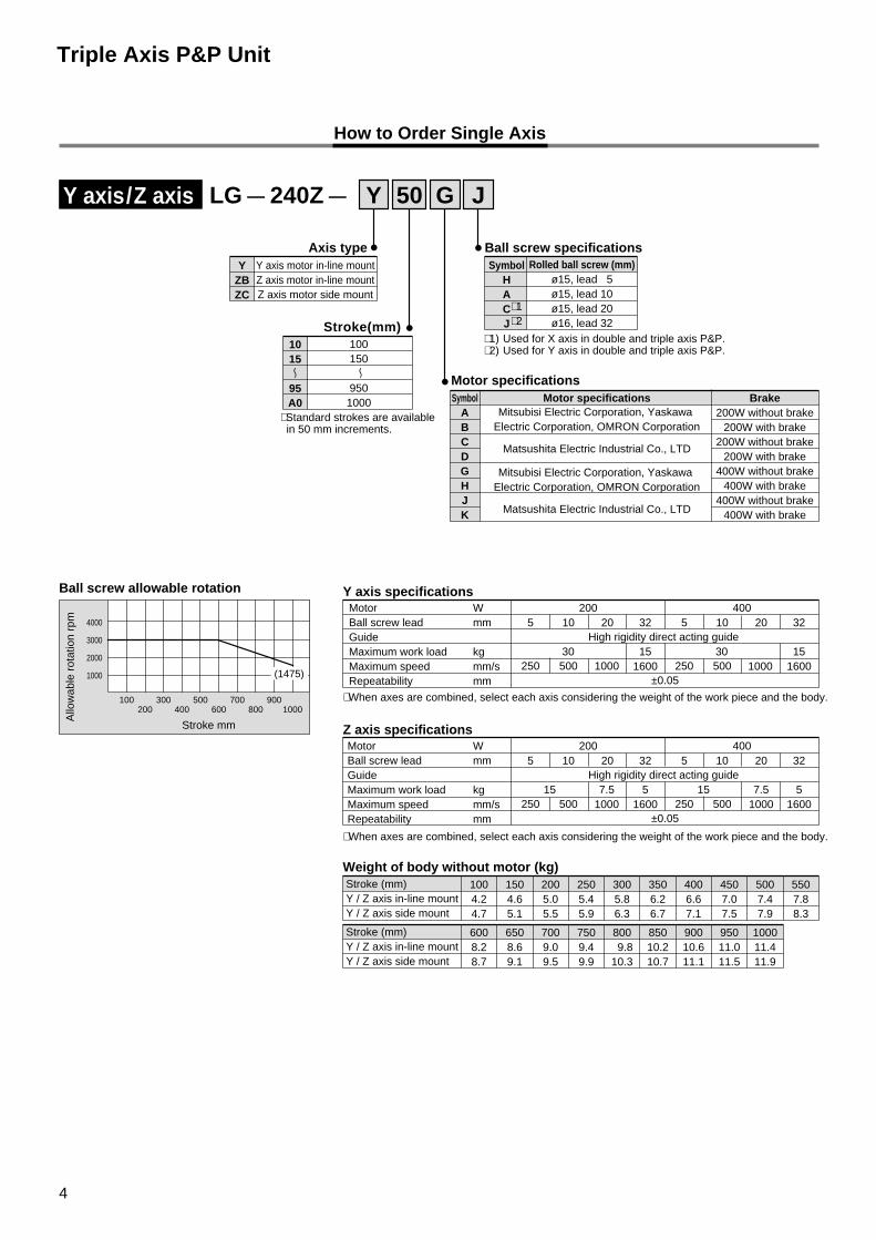
LG — 240Z — 50Y G J
Stroke(mm)
Axis type
1015
95A0
100150
9501000
How to Order Single Axis
YZBZC
Y axis motor in-line mountZ axis motor in-line mountZ axis motor side mount
∗ When axes are combined, select each axis considering the weight of the work piece and the body.
∗ When axes are combined, select each axis considering the weight of the work piece and the body.
Y axis specifications
Z axis specificationsMotorBall screw leadGuideMaximum work loadMaximum speedRepeatability
Wmm
kgmm/smm
2005 10
250 500
High rigidity direct acting guide
±0.05
20 32
15 7.51000
1551600
4005 10
250 500
20 32
7.51000
51600
MotorBall screw leadGuideMaximum work loadMaximum speedRepeatability
Wmm
kgmm/smm
2005 10
250 500 1000
High rigidity direct acting guide
±0.05
20 32
30 30151600
4005 10
250 500
20 32
100015
1600
Y axis/Z axis
Ball screw specifications Symbol
HACJ
Rolled ball screw (mm)ø15, lead 5ø15, lead 10ø15, lead 20ø16, lead 32
Motor specificationsMotor specifications
Mitsubisi Electric Corporation, Yaskawa Electric Corporation, OMRON Corporation
Matsushita Electric Industrial Co., LTD
Mitsubisi Electric Corporation, Yaskawa Electric Corporation, OMRON Corporation
Matsushita Electric Industrial Co., LTD
Brake200W without brake
200W with brake200W without brake
200W with brake400W without brake
400W with brake400W without brake
400W with brake
SymbolABCDGHJK
4
Weight of body without motor (kg)1004.24.7
1504.65.1
2005.05.5
2505.45.9
3005.86.3
3506.26.7
4006.67.1
4507.07.5
5007.47.9
5507.88.3
Stroke (mm)Y / Z axis in-line mountY / Z axis side mount
6008.28.7
6508.69.1
7009.09.5
7509.49.9
800 9.810.3
85010.210.7
90010.611.1
95011.011.5
100011.411.9
Stroke (mm)Y / Z axis in-line mountY / Z axis side mount
∗ Standard strokes are available in 50 mm increments.
Triple Axis P&P Unit
Ball screw allowable rotation
4000
3000
2000
1000
Allo
wab
le r
otat
ion
rpm
100200
300400
500600
700800
Stroke mm
9001000
(1475)
∗ 1) Used for X axis in double and triple axis P&P.∗ 2) Used for Y axis in double and triple axis P&P.
∗ 1∗ 2
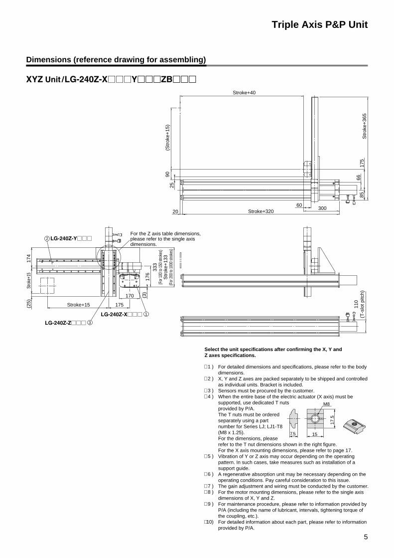
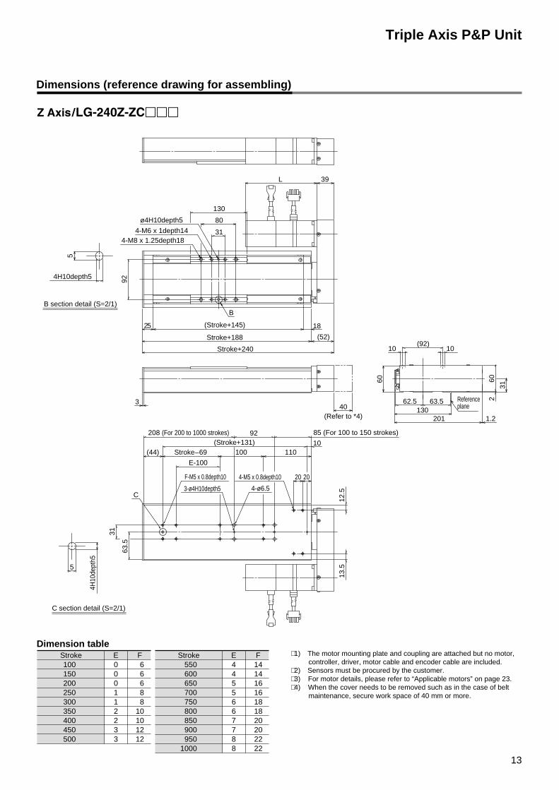
Dimensions (reference drawing for assembling)
For detailed dimensions and specifications, please refer to the body dimensions.X, Y and Z axes are packed separately to be shipped and controlled as individual units. Bracket is included.Sensors must be procured by the customer.When the entire base of the electric actuator (X axis) must be supported, use dedicated T nuts provided by P/A.The T nuts must be ordered separately using a part number for Series LJ; LJ1-T8 (M8 x 1.25).For the dimensions, please refer to the T nut dimensions shown in the right figure.For the X axis mounting dimensions, please refer to page 17.Vibration of Y or Z axis may occur depending on the operating pattern. In such cases, take measures such as installation of a support guide.A regenerative absorption unit may be necessary depending on the operating conditions. Pay careful consideration to this issue.The gain adjustment and wiring must be conducted by the customer.For the motor mounting dimensions, please refer to the single axis dimensions of X, Y and Z.For maintenance procedure, please refer to information provided by P/A (including the name of lubricant, intervals, tightening torque of the coupling, etc.).For detailed information about each part, please refer to information provided by P/A.
Triple Axis P&P Unit
M8
17.5
157.5
∗ 1 )
∗ 2 )
∗ 3 ) ∗ 4 )
∗ 5 )
∗ 6 )
∗ 7 ) ∗ 8 )
∗ 9 )
∗ 10)
5
(Str
oke+
15)
Stroke+40
Stroke+320300
60
8566
175
Str
oke+
365
20
9025
333
(For
100
to 1
50 st
roke
s)S
trok
e+13
3(F
or 2
00 to
100
0 str
okes
)
For the Z axis table dimensions, please refer to the single axis dimensions.
170
175
Stro
ke+1
5
(3)
176
110
(T-s
lot p
itch)
Stroke+15(25)
174
2
3
1
Select the unit specifications after confirming the X, Y and Z axes specifications.
6
Triple Axis P&P Unit
Str
oke+
365
175
85
30060
Stroke+320
Stroke+40
(Str
oke+
15)
110
(T-s
lot p
itch)
9025
20
66
359
(For
100
to 1
50 st
roke
s)S
trok
e+15
9(F
or 2
00 to
100
0 str
okes
)
176
110
175
170
Stroke+15
Stro
ke+1
520
0(2
5)
(3)
1
3
2
M8
17.5
157.5
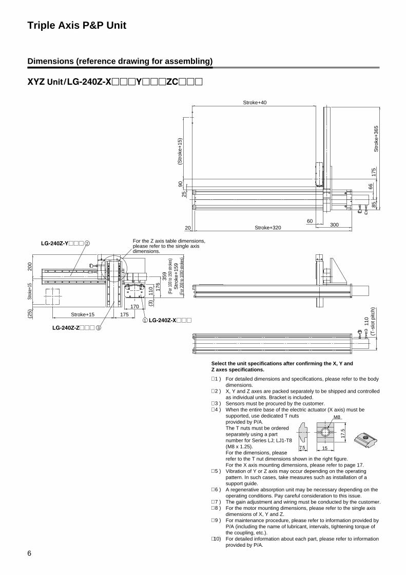
Dimensions (reference drawing for assembling)
For the Z axis table dimensions, please refer to the single axis dimensions.
Select the unit specifications after confirming the X, Y and Z axes specifications.
For detailed dimensions and specifications, please refer to the body dimensions.X, Y and Z axes are packed separately to be shipped and controlled as individual units. Bracket is included.Sensors must be procured by the customer.When the entire base of the electric actuator (X axis) must be supported, use dedicated T nuts provided by P/A.The T nuts must be ordered separately using a part number for Series LJ; LJ1-T8 (M8 x 1.25).For the dimensions, please refer to the T nut dimensions shown in the right figure.For the X axis mounting dimensions, please refer to page 17.Vibration of Y or Z axis may occur depending on the operating pattern. In such cases, take measures such as installation of a support guide.A regenerative absorption unit may be necessary depending on the operating conditions. Pay careful consideration to this issue.The gain adjustment and wiring must be conducted by the customer.For the motor mounting dimensions, please refer to the single axis dimensions of X, Y and Z.For maintenance procedure, please refer to information provided by P/A (including the name of lubricant, intervals, tightening torque of the coupling, etc.).For detailed information about each part, please refer to information provided by P/A.
∗ 1 )
∗ 2 )
∗ 3 ) ∗ 4 )
∗ 5 )
∗ 6 )
∗ 7 ) ∗ 8 )
∗ 9 )
∗ 10)
For the Z axis table dimensions, please refer to the single axis dimensions.
7
130
120(23)
86(90)(25)
Str
oke+
1513
021
1
2
Stroke+214
Stroke+191
Stroke+15 60
63.5
Rreference plane
Stro
ke—
8(F
or 1
00 to
150
stro
kes)
192
(For
200
to 1
000
stro
kes)
Str
oke+
214
Str
oke+
191
(23)
LG-240Z-Y□□□�
LG-240Z-Z□□□�
Triple Axis P&P Unit
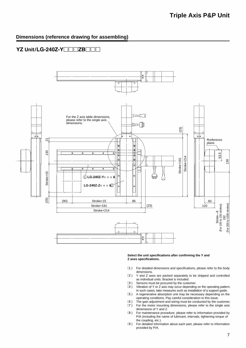
For detailed dimensions and specifications, please refer to the body dimensions.Y and Z axes are packed separately to be shipped and controlled as individual units. Bracket is included.Sensors must be procured by the customer.Vibration of Y or Z axis may occur depending on the operating pattern. In such cases, take measures such as installation of a support guide.A regenerative absorption unit may be necessary depending on the operating conditions. Pay careful consideration to this issue.The gain adjustment and wiring must be conducted by the customer.For the motor mounting dimensions, please refer to the single axis dimensions of Y and Z.For maintenance procedure, please refer to information provided by P/A (including the name of lubricant, intervals, tightening torque of the coupling, etc.).For detailed information about each part, please refer to information provided by P/A.
∗ 1 )
∗ 2 ) ∗ 3 ) ∗ 4 )
∗ 5 )
∗ 6 ) ∗ 7 )
∗ 8 )
∗ 9 )
Dimensions (reference drawing for assembling)
Select the unit specifications after confirming the Y and Z axes specifications.
8
Dimensions (reference drawing for assembling)
130
63.5
120
60(23)
86(90)(25)
1
2
130
18
Stroke+214
Stroke+191
Stroke+15
Str
oke+
15
Reference plane
Str
oke
—8
(For
100
to 1
50 s
trok
es)
192
(For
200
to 1
000
stro
kes)
Str
oke+
240
Str
oke+
188
(52)
LG-240Z-Y□□□�
LG-240Z-Z□□□�
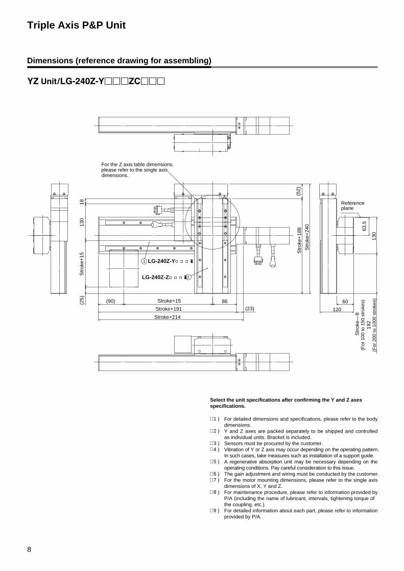
Triple Axis P&P Unit
For detailed dimensions and specifications, please refer to the body dimensions.Y and Z axes are packed separately to be shipped and controlled as individual units. Bracket is included.Sensors must be procured by the customer.Vibration of Y or Z axis may occur depending on the operating pattern. In such cases, take measures such as installation of a support guide.A regenerative absorption unit may be necessary depending on the operating conditions. Pay careful consideration to this issue.The gain adjustment and wiring must be conducted by the customer.For the motor mounting dimensions, please refer to the single axis dimensions of X, Y and Z.For maintenance procedure, please refer to information provided by P/A (including the name of lubricant, intervals, tightening torque of the coupling, etc.).For detailed information about each part, please refer to information provided by P/A.
∗ 1 )
∗ 2 )
∗ 3 ) ∗ 4 )
∗ 5 )
∗ 6 ) ∗ 7 ) ∗ 8 )
∗ 9 )
For the Z axis table dimensions, please refer to the single axis dimensions.
Select the unit specifications after confirming the Y and Z axes specifications.
Dimensions (reference drawing for assembling)
110
105
57
1515
40
304-M8 x 1.25thread depth 16
2-ø8H7depth10
40
Polyurethane stopper
Home position gauge
30
110
110(T-slot pitch)
110
(T-s
lot p
itch)
170
18
9.4
45°
11.5
104.5
T-slot dimensions
110
18
10
Stroke+320
Stroke+300
200
180(Refer to 4∗ ) (Refer to 4∗ )
(Refer to 4∗ )(Refer to 4∗ )
9
Stroke+240(Table movement range)
L
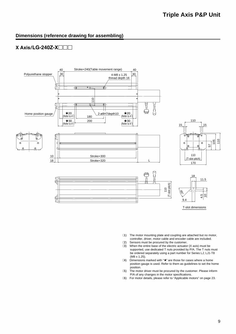
∗ 1) The motor mounting plate and coupling are attached but no motor, controller, driver, motor cable and encoder cable are included.
∗ 2) Sensors must be procured by the customer.∗ 3) When the entire base of the electric actuator (X axis) must be
supported, use dedicated T nuts provided by P/A. The T nuts must be ordered separately using a part number for Series LJ; LJ1-T8 (M8 x 1.25).
∗ 4) Dimensions marked with “★ ” are those for cases where a home position gauge is used. Refer to them as guidelines to set the home position.
∗ 5) The motor driver must be procured by the customer. Please inform P/A of any changes in the motor specifications.
∗ 6) For motor details, please refer to “Applicable motors” on page 23.
Triple Axis P&P Unit
Dimensions (reference drawing for assembling)
Urethane stopper
Home position gauge
10
Triple Axis P&P Unit
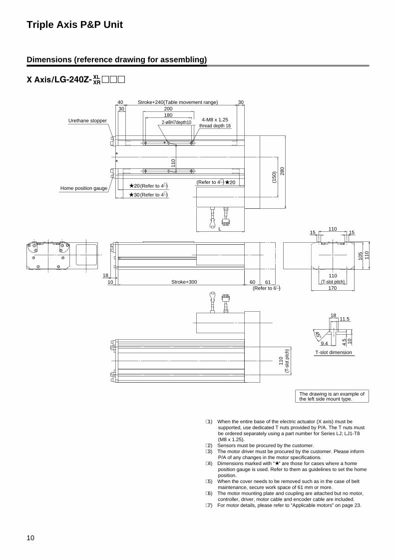
∗ 1) When the entire base of the electric actuator (X axis) must be supported, use dedicated T nuts provided by P/A. The T nuts must be ordered separately using a part number for Series LJ; LJ1-T8 (M8 x 1.25).
∗ 2) Sensors must be procured by the customer.∗ 3) The motor driver must be procured by the customer. Please inform
P/A of any changes in the motor specifications.∗ 4) Dimensions marked with “★ ” are those for cases where a home
position gauge is used. Refer to them as guidelines to set the home position.
∗ 5) When the cover needs to be removed such as in the case of belt maintenance, secure work space of 61 mm or more.
∗ 6) The motor mounting plate and coupling are attached but no motor, controller, driver, motor cable and encoder cable are included.
∗ 7) For motor details, please refer to “Applicable motors” on page 23.
280
61(Refer to 6∗ )
Stroke+240(Table movement range)
(150
)
60
L
18 110(T-slot pitch)
105
110
1515110
170
9.4
45°
104.5
1811.5
10 Stroke+300
304030
110
(T-s
lot p
itch)
110
200180
The drawing is an example of the left side mount type.
T-slot dimension
2-ø8H7depth10 4-M8 x 1.25thread depth 16
(Refer to 4∗ )
(Refer to 4∗ )
(Refer to 4∗ )
11
Dimensions (reference drawing for assembling)
92
(Stroke+131) 10
L
Triple Axis P&P Unit
2-M5 x 0.8Effective screw length 10
4-M6 x 1depth14
4-M8 x 1.25depth18
12
12.5
13.5
6
Reference plane
1010(92)
130
63.562.5
6160
31
(26)
14
130
26
14
3
2020
21
D
25
3
C
31
57
D section detail (S=2/1)
63.5
(Stroke+145)
Stroke+191
Stroke+214
80
31ø4H10depth5
126
2-M5 x 0.8Effective screw length 10
4-M5 x 0.8depth10F-M5 x 0.8depth10
4-ø6.5
(26)(44) 110100Stroke–69
E-100
92 85(For 100 to 150 strokes)
3-ø4H10depth5
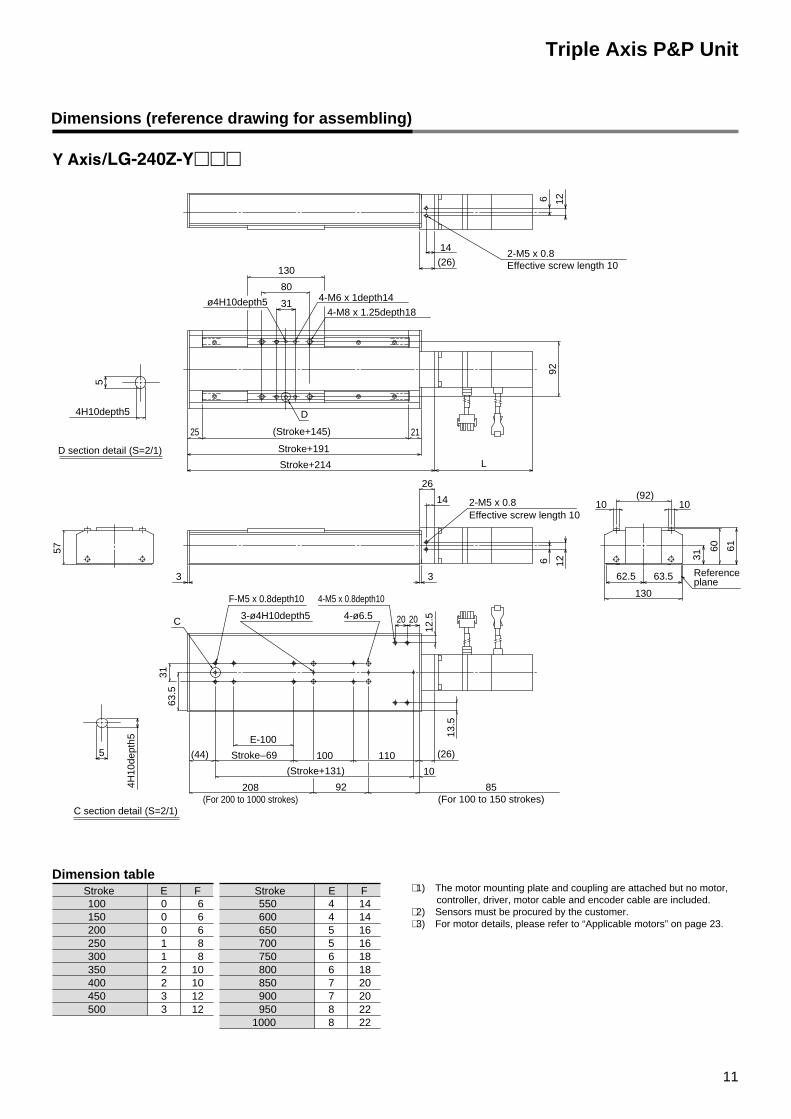
∗ 1) The motor mounting plate and coupling are attached but no motor, controller, driver, motor cable and encoder cable are included.
∗ 2) Sensors must be procured by the customer.∗ 3) For motor details, please refer to “Applicable motors” on page 23.
1235001234501024001023508130081250602006015060100
Stroke FE Stroke FE
Dimension table
2289502281000
207900207850186800186750165700165650144600144550
C section detail (S=2/1)
208(For 200 to 1000 strokes)
4H10depth5
5
4H10
dept
h5
5
12
Triple Axis P&P Unit
1235001234501024001023508130081250602006015060100
Stroke FE Stroke FE
2289502281000
207900207850186800186750165700165650144600144550
92
(Stroke+131) 10
L
2-M5 x 0.8Effective screw length 10
4-M6 x 1depth14
4-M8 x 1.25depth18
12
12.5
13.5
6
Reference plane
1010(92)
130
63.562.5
6160
31
(26)
14
130
26
14
3
2020
21
D
25
3
C
31
57
63.5
(Stroke+145)
Stroke+191
Stroke+214
80
31ø4H10depth 5
126
2-M5 x 0.8Effective screw length 10
4-M5 x 0.8depth10F-M5 x 0.8depth10
4-ø6.5
(26)(44) 110100Stroke–69
E-100
92
3-ø4H10depth5
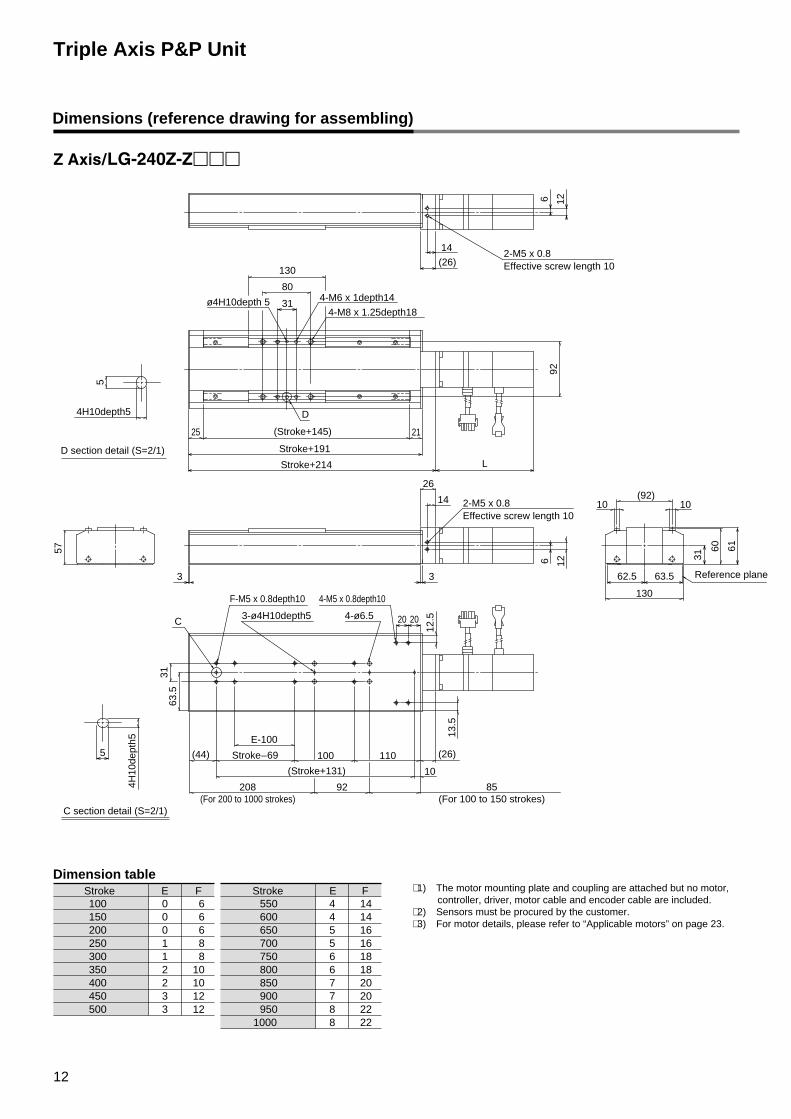
∗ 1) The motor mounting plate and coupling are attached but no motor, controller, driver, motor cable and encoder cable are included.
∗ 2) Sensors must be procured by the customer.∗ 3) For motor details, please refer to “Applicable motors” on page 23.
Dimension table
D section detail (S=2/1)
C section detail (S=2/1)
4H10depth5
5
4H10
dept
h5
5
Dimensions (reference drawing for assembling)
208(For 200 to 1000 strokes)
85(For 100 to 150 strokes)
13
92
123500123450102400102350
8130081250602006015060100
Stroke FE Stroke FE
2289502281000
207900207850186800186750165700165650144600144550
12.5
13.5
63.5
31
ø4H10depth5
4-M6 x 1depth144-M8 x 1.25depth18
39L
130
(Stroke+145)
F-M5 x 0.8depth10 4-M5 x 0.8depth10
3-ø4H10depth5 4-ø6.5
92
110
2020
100(44)
C
Stroke–69
E-100
25
3
Stroke+188
Stroke+240
80
18
(52)
40(Refer to *4)
31
B
Triple Axis P&P Unit
(Stroke+131) 10
∗ 1) The motor mounting plate and coupling are attached but no motor, controller, driver, motor cable and encoder cable are included.
∗ 2) Sensors must be procured by the customer.∗ 3) For motor details, please refer to “Applicable motors” on page 23.∗ 4) When the cover needs to be removed such as in the case of belt
maintenance, secure work space of 40 mm or more.
B section detail (S=2/1)
C section detail (S=2/1)
4H10depth5
5
4H10
dept
h5
5
Dimension table
60
1010
1.2201
602
31
13063.5
(92)
62.5 Referenceplane
Dimensions (reference drawing for assembling)
85 (For 100 to 150 strokes)208 (For 200 to 1000 strokes)
17
Electric Actuator/Maintenance Guide 1Be sure to read before handling.
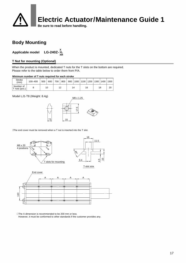
Body Mounting
Applicable model LG-240Z-XXLXR
T Nut for mounting (Optional)
When the product is mounted, dedicated T nuts for the T slots on the bottom are required.Please refer to the table below to order them from P/A.
Minimum number of T nuts required for each strokeStroke(mm)
∗ The end cover must be removed when a T nut is inserted into the T slot.
∗ The A dimension is recommended to be 200 mm or less. However, it must be conformed to other standards if the customer provides any.
T-slot size
M6 x 204 positions
T slots for mounting9.4
45°
10
4.5
18
11.5
110
A A A A
End cover
7.5
M8 x 1.25
17.5
15
18
Pulley cover removal process
Motor mounting process
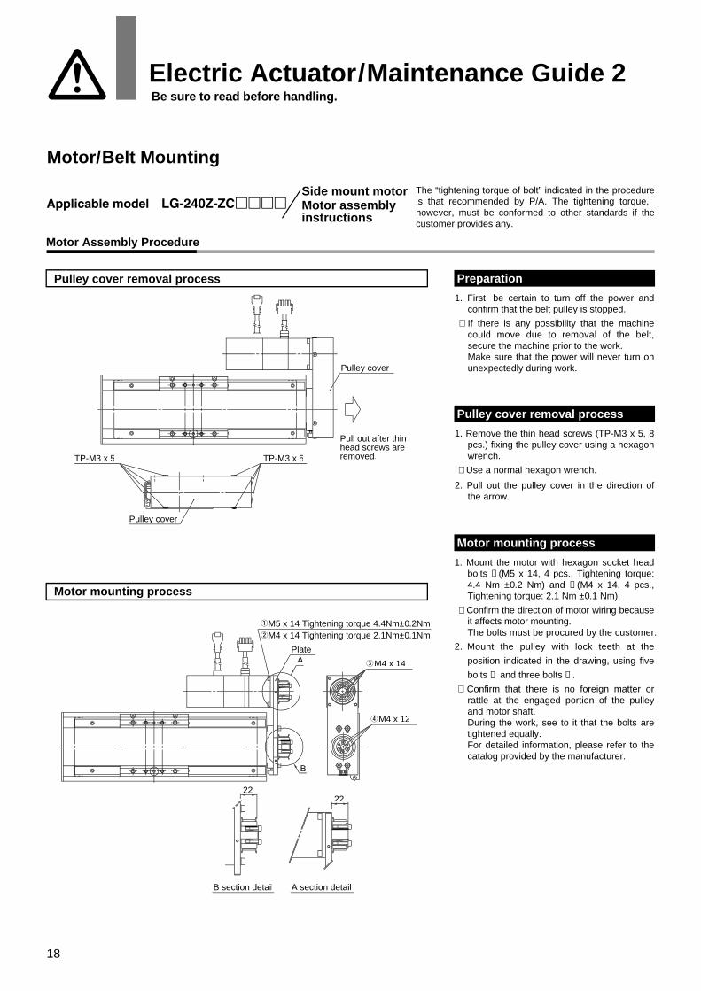
1. First, be certain to turn off the power and confirm that the belt pulley is stopped.
∗ If there is any possibility that the machine could move due to removal of the belt, secure the machine prior to the work.Make sure that the power will never turn on unexpectedly during work.
Preparation
1. Remove the thin head screws (TP-M3 x 5, 8 pcs.) fixing the pulley cover using a hexagon wrench.
∗ Use a normal hexagon wrench.
2. Pull out the pulley cover in the direction of the arrow.
Pulley cover removal process
1. Mount the motor with hexagon socket head bolts ➀ (M5 x 14, 4 pcs., Tightening torque: 4.4 Nm ±0.2 Nm) and ➁ (M4 x 14, 4 pcs., Tightening torque: 2.1 Nm ±0.1 Nm).
∗ Confirm the direction of motor wiring because it affects motor mounting.The bolts must be procured by the customer.
2. Mount the pulley with lock teeth at the
position indicated in the drawing, using five
bolts ➂ and three bolts ➃ .
∗ Confirm that there is no foreign matter or rattle at the engaged portion of the pulley and motor shaft.During the work, see to it that the bolts are tightened equally.For detailed information, please refer to the catalog provided by the manufacturer.
Motor mounting process
2222
B
B section detail
A
A section detail
M4 x 12
M4 x 14
M5 x 14 Tightening torque 4.4Nm±0.2NmM4 x 14 Tightening torque 2.1Nm±0.1Nm
Plate
TP-M3 x 5 TP-M3 x 5
Pull out after thinhead screws areremoved.
Pulley cover
Pulley cover
Side mount motorMotor assembly instructions
Motor Assembly Procedure
The “tightening torque of bolt” indicated in the procedure is that recommended by P/A. The tightening torque, however, must be conformed to other standards if the customer provides any.
Electric Actuator/Maintenance Guide 2 Be sure to read before handling.
Motor/Belt Mounting
19
Belt mounting process
Belt tension adjustment
Pulley cover mounting process
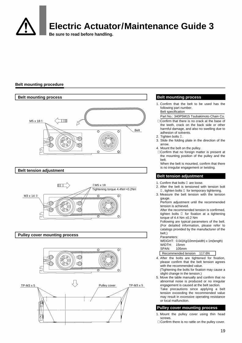
1. Confirm that the belt to be used has the following part number.Belt specificationPart No.: 340P5M15 Tsubakimoto Chain Co.
∗ Confirm that there is no crack at the base of the teeth, crack on the back side or other harmful damage, and also no swelling due to adhesion of solvents.
2. Tighten bolts ➀ .3. Slide the folding plate in the direction of the
arrow.4. Mount the belt on the pulley. ∗ Confirm that no foreign matter is present at
the mounting position of the pulley and the belt.When the belt is mounted, confirm that there is no irregular engagement or twisting.
Belt mounting process
1. Confirm that bolts ➀ are loose.2. After the belt is tensioned with tension bolt
➁ , tighten bolts ➀ for temporary tightening.3. Measure the belt tension with the tension
gauge. Perform adjustment until the recommended tension is achieved.After the recommended tension is confirmed, tighten bolts ➀ for fixation at a tightening torque of 4.4 Nm ±0.2 NmFollowing are typical parameters of the belt. (For detailed information, please refer to catalogs provided by the manufacturer of the belt.)Parameters: WEIGHT: 0.041Kg/10mm(width) x 1m(length)WIDTH: 15mmSPAN: 105mm Recommended tension 117.6N
4. After the bolts are tightened for fixation, please confirm that the belt tension agrees with the recommended value.
(Tightening the bolts for fixation may cause a slight change in the tension.)
5. Move the table manually and confirm that no abnormal noise is produced or no irregular engagement is caused at the belt section.Take precautions since applying a belt tension exceeding the recommended value may result in excessive operating resistance or local malfunction.
Belt tension adjustment
1. Mount the pulley cover using thin head screws.
∗ Confirm there is no rattle on the pulley cover.
Pulley cover mounting process
Pulley coverTP-M3 x 5 TP-M3 x 5
M5 x 18
Belt
M3 x 14
M5 x 18Tightening torque 4.4Nm±0.2Nm
Belt mounting procedure
Electric Actuator/Maintenance Guide 3Be sure to read before handling.
20
Side mount motorMotor assembly instructions
Pulley cover
26
Pulley with lock teeth
A section detail
A section Plate
M4 x 14M6 x 20 Tightening torque 6.8Nm±0.3NmM5 x 18 Tightening torque 4.4Nm±0.1Nm
TP-M3 x 5TP-M3 x 5
Pulley cover
Electric Actuator/Maintenance Guide 4Be sure to read before handling.
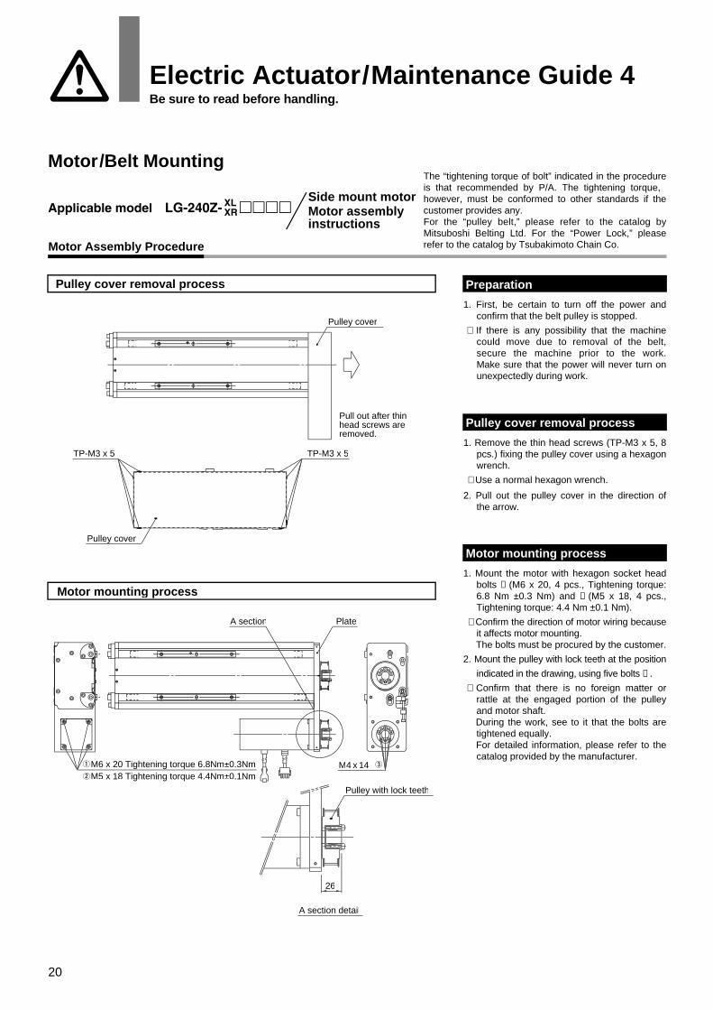
Motor/Belt MountingThe “tightening torque of bolt” indicated in the procedure is that recommended by P/A. The tightening torque, however, must be conformed to other standards if the customer provides any.For the “pulley belt,” please refer to the catalog by Mitsuboshi Belting Ltd. For the “Power Lock,” please refer to the catalog by Tsubakimoto Chain Co.
Pulley cover removal process
Motor Assembly Procedure
Motor mounting process
Pull out after thinhead screws areremoved.
1. First, be certain to turn off the power and confirm that the belt pulley is stopped.
∗ If there is any possibility that the machine could move due to removal of the belt, secure the machine prior to the work.Make sure that the power will never turn on unexpectedly during work.
Preparation
1. Remove the thin head screws (TP-M3 x 5, 8 pcs.) fixing the pulley cover using a hexagon wrench.
∗ Use a normal hexagon wrench.
2. Pull out the pulley cover in the direction of the arrow.
Pulley cover removal process
1. Mount the motor with hexagon socket head bolts ➀ (M6 x 20, 4 pcs., Tightening torque: 6.8 Nm ±0.3 Nm) and ➁ (M5 x 18, 4 pcs., Tightening torque: 4.4 Nm ±0.1 Nm).
∗ Confirm the direction of motor wiring because it affects motor mounting.
The bolts must be procured by the customer.
2. Mount the pulley with lock teeth at the position
indicated in the drawing, using five bolts ➂ .
∗ Confirm that there is no foreign matter or rattle at the engaged portion of the pulley and motor shaft.
During the work, see to it that the bolts are tightened equally.
For detailed information, please refer to the catalog provided by the manufacturer.
Motor mounting process
21
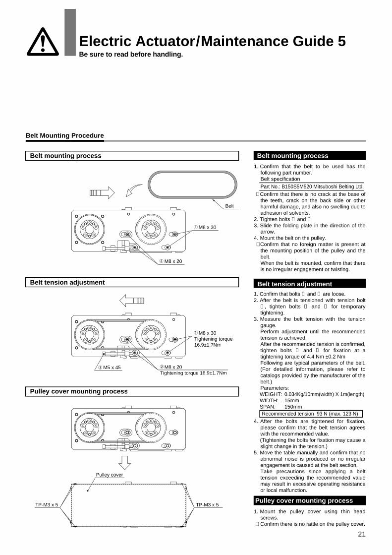
1. Confirm that the belt to be used has the following part number.Belt specificationPart No.: B150S5M520 Mitsuboshi Belting Ltd.
∗ Confirm that there is no crack at the base of the teeth, crack on the back side or other harmful damage, and also no swelling due to adhesion of solvents.
2. Tighten bolts ➀ and ➁3. Slide the folding plate in the direction of the
arrow.4. Mount the belt on the pulley. ∗ Confirm that no foreign matter is present at
the mounting position of the pulley and the belt.When the belt is mounted, confirm that there is no irregular engagement or twisting.
1. Confirm that bolts ➀ and ➁ are loose.2. After the belt is tensioned with tension bolt
➂ , tighten bolts ➀ and ➁ for temporary tightening.
3. Measure the belt tension with the tension gauge. Perform adjustment until the recommended tension is achieved.After the recommended tension is confirmed, tighten bolts ➀ and ➁ for fixation at a tightening torque of 4.4 Nm ±0.2 NmFollowing are typical parameters of the belt. (For detailed information, please refer to catalogs provided by the manufacturer of the belt.)Parameters:WEIGHT: 0.034Kg/10mm(width) X 1m(length)WIDTH: 15mmSPAN: 150mm Recommended tension 93 N (max. 123 N)
4. After the bolts are tightened for fixation, please confirm that the belt tension agrees with the recommended value.
(Tightening the bolts for fixation may cause a slight change in the tension.)
5. Move the table manually and confirm that no abnormal noise is produced or no irregular engagement is caused at the belt section.Take precautions since applying a belt tension exceeding the recommended value may result in excessive operating resistance or local malfunction.
1. Mount the pulley cover using thin head screws.
∗ Confirm there is no rattle on the pulley cover.
Pulley cover mounting processTP-M3 x 5 TP-M3 x 5
Pulley cover
M8 x 20Tightening torque 16.9±1.7Nm
M5 x 45
M8 x 30Tightening torque16.9±1.7Nm
M8 x 20
M8 x 30
Belt
Electric Actuator/Maintenance Guide 5Be sure to read before handling.
Belt mounting process
Belt tension adjustment
Pulley cover mounting process
Belt Mounting Procedure
Belt mounting process
Belt tension adjustment
22
Motor assembly instructions
Motor Assembly Procedure
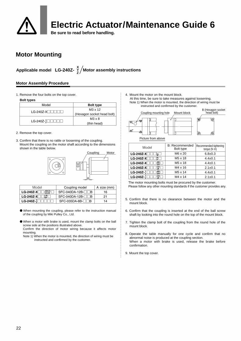
1. Remove the four bolts on the top cover.
2. Remove the top cover. 3. Confirm that there is no rattle or loosening of the coupling. Mount the coupling on the motor shaft according to the dimensions shown in the table below.
4. Mount the motor on the mount block. At this time, be sure to take measures against loosening. Note 1) When the motor is mounted, the direction of wiring must be
instructed and confirmed by the customer.
5. Confirm that there is no clearance between the motor and the mount block.
6. Confirm that the coupling is inserted at the end of the ball screw shaft by looking into the round hole on the top of the mount block.
7. Tighten the clamp bolt of the coupling from the round hole of the mount block.
8. Operate the table manually for one cycle and confirm that no abnormal noise is produced at the coupling section.When a motor with brake is used, release the brake before confirmation.
The motor mounting bolts must be procured by the customer.Please follow any other mounting standards if the customer provides any.
● When mounting the coupling, please refer to the instruction manual of the coupling by Miki Pulley Co., Ltd.
● When a motor with brake is used, mount the clamp bolts on the ball screw side at the positions illustrated above.Confirm the direction of motor wiring because it affects motor mounting.
Note 1) When the motor is mounted, the direction of wiring must be instructed and confirmed by the customer.
YZYZ
XYZ
YZ
LMNP
ABCDGHJK
Electric Actuator/Maintenance Guide 6Be sure to read before handling.
Motor Mounting
23
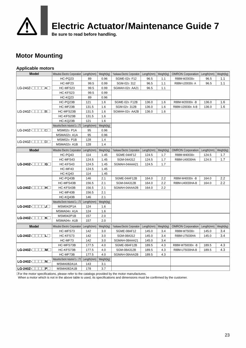
Applicable motors
∗ For the motor specifications, please refer to the catalogs provided by the motor manufactures. When a motor which is not in the above table is used, its specifications and dimensions must be confirmed by the customer.
Mitsubisi Electric Corporation
HC-PQ23
HC-MF23
HC-MFS23
HC-KFS23
HC-KQ23
HC-PQ23B
HC-MF23B
HC-MFS23B
HC-KFS23B
HC-KQ23B
Matsushita Electric Industrial Co., LTD
MSM02□P1A
MSMA02□A1A
MSM02□P1B
MSMA02□A1B
Length(mm)
89
99.5
99.5
99.5
89
121
131.5
131.5
131.5
121
Length(mm)
95
95
128
128
Weight(kg)
0.96
0.99
0.99
0.99
0.96
1.6
1.6
1.6
1.6
1.6
Weight(kg)
0.96
0.96
1.4
1.4
Yaskawa Electric Corporation
SGME-02□F12
SGM-02□312
SGMAH-02□AA21
SGME-02□F12B
SGM-02□312B
SGMAH-02□AA2B
Length(mm)
96.5
96.5
96.5
136.0
136.0
136.0
Weight(kg)
1.1
1.1
1.1
1.6
1.6
1.6
OMRON Corporation
R88M-W20030□R88M-U20030□A
R88M-W20030□-B
R88M-U20030□A-B
Length(mm)
96.5
96.5
136.0
136.0
Weight(kg)
1.11.1
1.61.6
Mitsubisi Electric Corporation
HC-PQ43
HC-MFS43
HC-KFS43
HC-MF43
HC-KQ43
HC-PQ43B
HC-MFS43B
HC-KFS43B
HC-MF43B
HC-KQ43B
Matsushita Electric Industrial Co., LTD
MSM042P1A
MSMA04□A1A
MSM042P1B
MSMA04□A1B
Length(mm)
114
124.5
124.5
124.5
114
146
156.5
156.5
156.5
146
Length(mm)
124
124
157
157
Weight(kg)
1.45
1.45
1.45
1.45
1.45
2.1
2.1
2.1
2.1
2.1
Weight(kg)
1.6
1.6
2.0
2.0
Yaskawa Electric Corporation
SGME-04AF12
SGM-04A312
SGMAH-04AAA21
SGME-04AF12B
SGM-04A312B
SGMAH-04AAA2B
Length(mm)
124.5
124.5
124.5
164.0
164.0
164.0
Weight(kg)
1.7
1.7
1.7
2.2
2.2
2.2
OMRON Corporation
R88M-W40030□R88M-U40030HA
R88M-W40030□-B
R88M-U40030HA-B
Length(mm)
124.5
124.5
164.0
164.0
Weight(kg)
1.71.7
2.22.2
Mitsubisi Electric Corporation
HC-MFS73
HC-KFS73
HC-MF73
HC-MFS73B
HC-KFS73B
HC-MF73B
Matsushita Electric Industrial Co., LTD
MSMA082A1A
MSMA082A1B
Length(mm)
142
142
142
177.5
177.5
177.5
Length(mm)
143
178
Weight(kg)
3.0
3.0
3.0
4.0
4.0
4.0
Weight(kg)
3.1
3.7
Yaskawa Electric Corporation
SGME-08AF12
SGM-08A312
SGMAH-08AAA21
SGME-08AF12B
SGM-08A312B
SGMAH-08AAA2B
Length(mm)
145.0
145.0
145.0
189.5
189.5
189.5
Weight(kg)
3.4
3.4
3.4
4.3
4.3
4.3
OMRON Corporation
R88M-W75030□R88M-U75030HA
R88M-W750030□-B
R88M-U75030HA-B
Length(mm)
145.0
145.0
189.5
189.5
Weight(kg)
3.43.4
4.34.3
Electric Actuator/Maintenance Guide 7Be sure to read before handling.
Motor Mounting
24
Maintenance
Maintenance and inspection are necessary to maintain safe operation and performance of the electric actuator.The following instruction should be thoroughly understood before maintenance or inspection is conducted.1) Before conducting maintenance or inspection, confirm that the
motor driving power is turned off.At this time, take sufficient precautions since the table may move if an external force is applied.
2) Do not conduct inspection while the actuator is in operation.If inspection is unavoidable, it must never take place within the operating range of the actuator.
3) If any abnormality is found in periodic inspection, consult P/A immediately.
Maintenance
Daily Inspection
Conduct the following inspections before and after the operation of the actuator.
Inspection description
No scratches or bruises are found on the body.No adhesion of chips, dust, or liquid such as water is observed.
No abnormal noise or rattle is present.
No abnormal vibration, rattle or abnormal noise is present.
Inspection itemsBody appearance
Ball screw/TableBearing
Guide
Regular Inspection
Inspection after six months of operation or one month or more of non-operation
Inspection items
Body mountingBolts, screws
Ball screwguide
Coupling
Inspection description / Maintenance instruction
No loosening is observed.If the mounting part of the body comes loose, tighten at the specified torque.For the recommended torque, please refer to the table below.
Apply Alvania No. 2 (by Showa Shell Sekiyu K.K.) or equivalent to the ball screw threads after wiping off old grease, dust and dirt adhering to the surrounding surfaces.Apply the grease directly to the groove of the ball screw threads using a knife tool. Flatten the grease so that it will go in as deep as possible and repeat the stroke several times.For the guide, apply the above grease to the nipples using grease guns. The standard volume is 0.5 cc per block.As in the case of the ball screw threads, apply the grease after wiping off old grease, dust and dirt adhering to the surrounding surfaces.(Never use grease containing fluorine.)
No loosening of bolt is observed on the coupling.Replace the coupling if any loosening is observed.
Reapplying grease to ball screw and guide The top cover should be removed from the top of the body.
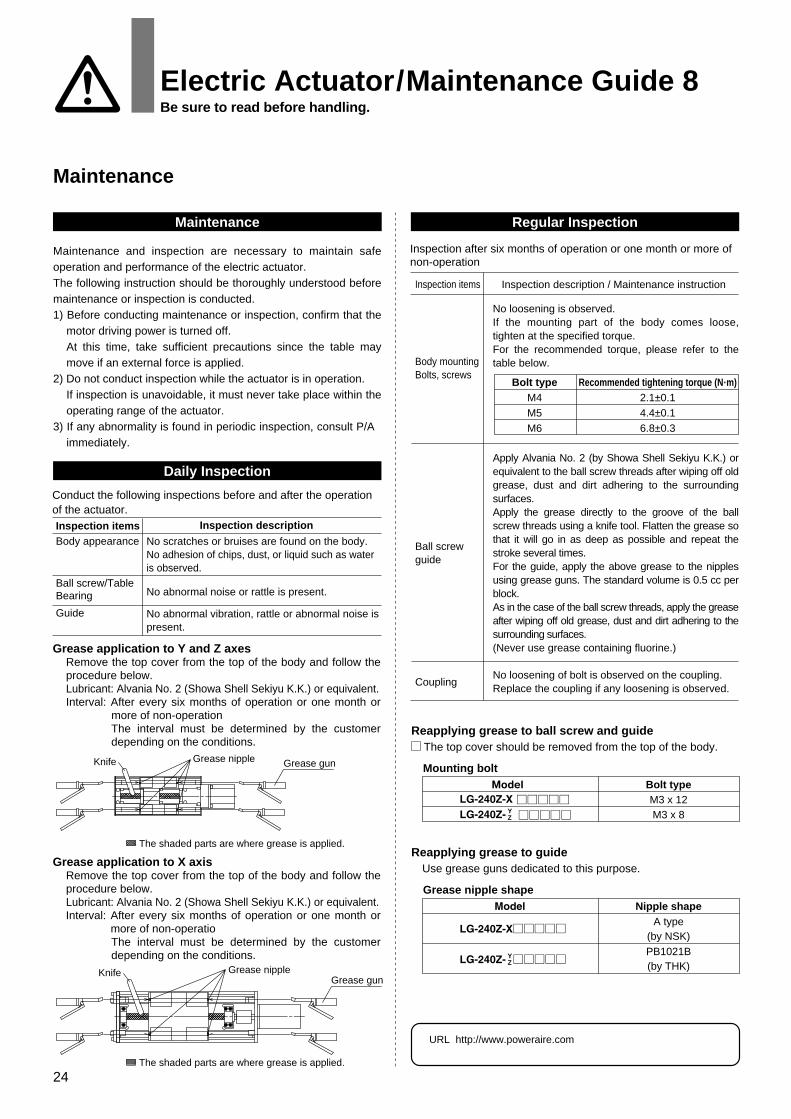
Grease application to Y and Z axesRemove the top cover from the top of the body and follow the procedure below.Lubricant: Alvania No. 2 (Showa Shell Sekiyu K.K.) or equivalent.Interval: After every six months of operation or one month or
more of non-operationThe interval must be determined by the customer depending on the conditions.
Grease application to X axisRemove the top cover from the top of the body and follow the procedure below.Lubricant: Alvania No. 2 (Showa Shell Sekiyu K.K.) or equivalent.Interval: After every six months of operation or one month or
more of non-operatioThe interval must be determined by the customer depending on the conditions.
Grease nipple shapeNipple shape
A type(by NSK)PB1021B(by THK)
Reapplying grease to guide Use grease guns dedicated to this purpose.
Knife
Knife
Grease gun
Grease gun
The shaded parts are where grease is applied.
Grease nipple
The shaded parts are where grease is applied.
Grease nipple
YZ
YZ
URL http://www.poweraire.com
Electric Actuator/Maintenance Guide 8Be sure to read before handling.