22
Electric Actuator Type EA 20 Instruction Manual - Provided by KTH Sales, Inc. - http://www.KTHSales.com ¬ ‡
| Date post: | 26-Jun-2018 |
| Category: |
Documents |
| Upload: | vuongkhanh |
| View: | 213 times |
| Download: | 0 times |

Electric Actuator Type EA 20
Instruction Manual - Provided by KTH Sales, Inc. - http://www.KTHSales.com
¬ ‡

2 ¬ ‡
The technical data givenare for general informa-tion purposes only. Theyimply no warranty ofany kind. Please consultour General Terms andConditions of Sale.
1. Introduction
This instruction manual contains the description,specification, installation instructions, start-up andmaintenance for the electric actuator Type EA 20.
1.1 DescriptionThe EA 20 is a compact, sturdy, electric actuatordesigned for a long service life. It is speciallysuitable for industrial applications.
Also available is an ISO interconnecting plateallowing the actuator to be mounted on almost anyvalve.
Due to its reliability, compact construction and highcorrosion resistance, the actuator can be used on2-way or 3-way ball valves, butterfly valves or anyother rotary mechanical element.

3¬ ‡
1.2 Specifications
Duty cycle: 100% at 77°F (25°C)70% at 122°F (50°C)
Nominal voltage: 100 – 120 V/200 – 240 V±10%, 50 – 60 Hz (selectable)24 VAC/DCother voltages on request
Rated performance: 12 VA (AC); 7 W (DC)Protection class: NEMA 4x, IP 65 as per DIN 40050
weatherproof and corrosion resistantOverload protection: Current-time dependent (self resetting)
The overload protection is designed toprotect both motor and power supply board.If the overload protection device has trig-gered, it will reset automatically when theunit has cooled down and the actuator willoperate again.
Electrical connection: unit plug 3 P+E according to DIN 43650additional cable port Pg 11 or 1/2" conduit plug
Operating time: approx. 6 sec/90° <)Operating angle: max. 270° (adjustable), set at 90° with 2
limit switchesNominal torque: 106 inch pounds/12 NmPeak torque: 221 inch pounds/25 NmAmbient temperature: 14°F – 122°F/-10°C – 50°C
(for temperatures below 14°F (-10°C) theheating element 198 190 142/...143should be installed)
Allowable humidity: 0 – 98%, non-condensingHousing material: PP GF (polypropylene glass-fiber reinforced)
external screws corrosion freePosition indicator: Visual, integratedInterconnecting plate: To ISO 5211/1 F 05 availableAuxiliary equipment: 2 additional switches incl. cams
4 additional switches incl. camsSpeed controller 10 to 80 sPotentiometer (1000 Ω for 2-way ballvalves, 2000 Ω for 3-way ball valves)
Weight: 4.4 pounds/2 kgSafety tested by SEVPerformance according to VDE

4 ¬ ‡
2. DesignThe electric actuator Type EA 20 consists of thefollowing:• Cover with integrated seals and clear position indicator cover• DC actuator motor• Permanently lubricated, ball bearings and gears• Power board for voltage selection, motor control and overload protection• Stroke limiter by means of 2 micro switches with adjustable cams• Support for auxiliary equipment (up to 4 extra micro switches)• Housing with plug and additional cable port for Pg 11 (1/2" conduit available on request)
Position indicator
Support for additional camsand switches
Gear box
Installation positionfor cable port Pg 11or 1/2" conduit plug
Housing
Power supply plug
Actuatormotor
Powerboard
Limitswitches

5¬ ‡
3. Installation3.1 Unpacking and inspectionPrior to shipment, the unit was carefully assembledand checked for proper operation.
Stroke limiting switches and cams were adjustedtogether with George Fischer ball valves. Addi-tional adjustment is not normally required for start-up.
Individually shipped, the actuator EA 20 is deliv-ered pre-adjusted in "Open"-position (A-B).
Please check that the unit is complete and forpossible transport damage.
Check that the actuator voltage is the same as thesupply or control voltage (factory set for 200-240VAC/50-60 Hz on voltage selectable model).
Dimensions
2.40" 3.35"
5.75".60"
2.52"
7.28"
4.76"
3.31
"1.
77"
5.83
"

6 ¬ ‡
3.2 Mechanical connection(Example George Fischer ball valve type 346)
Please note:• Each actuator is supplied in "Open" position• When mounting the valve, it must be in "Open" position• The stroke limiting switches and cams have been pre-adjusted at the factory. After mounting the actuator onto the valve, an additional fine adjustment must be performed (see 3.6 Adjustments).
Without manual override With manual override(for 2-way ball valves only)
Assembly of Type EA 20 Actuator andType 346 Ball Valve
actuator type EA 20
coupling
manual override lever
intermediate housingball valve brackettype 126, top half
bracket clamps
wedgescrews
coupling pieces
ball valve type 346
ball valve brackettype 126, bottom half
wedge

7¬ ‡
3.3 Electrical connectionThe standard version of the electric actuator TypeEA 20 is equipped with a 4-pole plug to connectthe incoming electric power.For outdoor installations, we recommend that theexternal wiring be either run inside a conduit usinga 1/2" conduit plug or that cable is run through aPg 11 cable joint connector.A 1/2" conduit plug is available as a directreplacement for the standard cable plug.If the Pg 11 cable joint connector is required, thestandard cable plug and internal wiring must beremoved and the Pg 11 installed into the existinghole.
Direct wiring using cable joint connector
Caution:Before removing the cover, switch off the powersupply. Internal components are under supplyvoltage! (AC)
inside actuatorcustomer connection
DC AC + L1 – N
PE
open A closed C
circuit board
connect groundto transformer

8 ¬ ‡
Actuator in position"Open" A – B
Bclosed
Aopen
Inside Actuator
Customer
gree
n
red
whi
te
brow
n
gree
n
red
blac
k
green/yellow
M = Motor
S1
= Limit switch open
S2
= Limit switch closed
L1 = Phase
N = Neutral
PE = Ground
Wiring Diagram Type EA 20 Actuator – AC Voltage
gree
n
red

9¬ ‡
3.4 Voltage SelectionThis actuator is supplied as 200–240 VAC.100–120 VAC may be selected by changing thejumper connections on the power board as shownbelow.
Do not change while under voltage!
3.5 Installation and connection ofaccessories
The electrical actuator Type EA 20 is equippedwith fastening points which allow for modularaccessories to be mounted.The configuration of these points is described insection 2. The electrical connection is made bymeans of a second cable plug or a threadedcable joint (depending on the number of connect-ing wires). The respective kits are prepared forinstallation, the electric cables are cut to size andpackaged accordingly.In the following sections, the correspondingassembly points and the wiring are illustrated.
100 – 120 VAC
200 – 240 VAC

10 ¬ ‡
3.5.1 Additional limit switches S5 and S6The cams for the additional switches can beadjusted as required.
Please note:The cams for the limit positions S1 and S2 shouldnot have to be adjusted.
1 Additional switching cams
2 Limit switch S5, S6 or S5 to S8
Part number 199 190 139 Part number 199 190 138/...149
inside actuatorcustomer
connection
blac
kw
hite
blac
kre
d

11¬ ‡
Diagram(2 additional switches)
Procedure• Remove second cable plug• Install a 1/2" conduit plug or a Pg 11 joint connector• Cable entry: be careful that no movable parts are disturbed• Press flat-pin terminals .19"x.02"/4.8x0.5 mm onto the ends of the wires• Connect to the appropriate switches
Electrical connectionWhen two additional limitswitches are installed, theelectrical connection is via asecond cable plug which isprovided as part of the kit.
Please note:Both switches are used as"closed" switches.
"Open" function by repluggingthe flat-pin terminals fromposition (4) to (2).
blue
black
yellow
4
black
2
S5 11S6
4 2
213

12 ¬ ‡
Part number 199 190 146 NPN Part number 199 190 148Part number 199 190 147 PNP
3.5.2 Inductive limit switchesThe mechanical installation of these switches isidentical to those under 3.5.1.An additional metal part must be mounted so thatthe active surface of the inductive switch can beactivated.
inside actuator
customerconnection
whi
tebl
ack
red
whi
tebl
ack
gree
n
whi
tebl
ack
whi
tebl
ack

13¬ ‡
3.5.3 PotentiometerThe potentiometer must be mounted on closedvalves. Before mounting, the potentiometer must beturned to the end position, so that 0-Ω is measuredbetween the red and the white connecting wires.
Part number 199 190 140
whi
te
red
blac
k
inside actuatorcustomer connection

14 ¬ ‡
Position of actuator Resistance acrossvalve terminal 1 and 2
2-way model 90° <) "Closed" C 0 Ω"Open" AB 1000 Ω
3-way model 180° <) "Open" B 0 Ω"Closed" C 1000 Ω"Open" A 2000 Ω
Electrical connection
rotateclockwiseCW
rotatedcounterclockwiseCCW
plug
whi
tere
d
blac
k
1
3
2

15¬ ‡
a) Installation
positionindicator
attach wiring diagramin cover
power board
motor
inside actuatorcustomer conection
EF
D
4
S4
S3S4
S3
cable receptable 0.19" x 0.02" (4.8 x 0.5 mm)
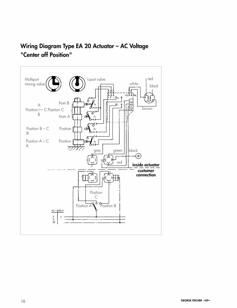
3.5.4 Center stop positionTwo additional limit switches for a central position(3/3-way ball valve Type 343).
16 ¬ ‡
Wiring Diagram Type EA 20 Actuator – AC Voltage"Center off Position"
Multiportmixing valve
L-port valve
from B APosition — C Position C B from A
Position B – C PositionB
Position A – C PositionA
grey green black
red
PositionC
Position BPosition A
white
brown
red
black
inside actuatorcustomer
connection

17¬ ‡
The speed control is con-nected electrically with thisplug (2) on the power board.
3.5.5 Speed control (Vario)
T = 10 – 80 seconds, part number 199 190 144(The vario is driving the motor stepwise)
Potentiometer for timeadjustment
time is reducedtime is extended

18 ¬ ‡
3.5.6 Heating element
1 Adhesive surface2 Heating element is attached to the inside of the cover3 Temperature switch Switching point: on: 32°F/0°C off: 41°F/5°C4 With diode 220 VAC Without diode 110 VAC
100–240 VAC part number 199 190 14224 VAC/DC part number 199 190 143
4
3
1
2
inside actuatorcustomerconnection
red
whi
te
19¬ ‡
3.6 Start-up
a) Installation checkBefore starting, i.e. before connecting the actuatorto the power supply, the following points shouldbe carefully checked:• correct voltage• correct connection
b) AdjustmentsIf a complete George Fischer valve with actuator isdelivered, no additional adjustments are needed(always delivered in "Open" position).If an actuator is repaired or installed by a user, thelimit positions have to be re-adjusted and checked.These adjustments can only be done when thevalve is removed completely from the line. Pleasefollow the instructions carefully when adjusting the"Open" and "Closed" position. If in doubt, pleasecontact the nearest George Fischer sales office orrepresentative.
Procedure:(Precondition: Actuator/valve in "Open" position)• Adjustment to "Closed" position: Actuator runs in "Closed" direction until the exact "Closed" position is reached.• Move the "Closed" cam in "Closed" direction, until the switch contact is made.• Adjustment "Open" position: Same procedure as above ("Open" position adjust with "Open" cam)• Check adjustments and make corrections if required
Please note:The angle of movement for theactuator with manual overrideis limited.Make sure that these stops arenot forced (angle of movementmax. 92°).

20 ¬ ‡
c) Overload protectionThe actuator has full overload protection.
It is an electric overload protection, responding incase of overload and thus protecting the motoragainst overheating.
In this case the power supply must be discon-nected and the source of trouble must be elimi-nated (in most cases overload is caused by valveblockage).
After checking and re-connecting, the actuator isready to be used again.
4. Maintenance
The electric actuator Type EA 20 is maintenancefree.
If the unit is operated within the specified range,more than 200,000 cycles are feasible.
In case of any failures, please check• installation• valve
If the malfunctions cannot be repaired on site,please contact the nearest George Fischer repre-sentative.

21¬ ‡
Spare Parts for Electric ActuatorType EA 20
No. Description Mat. Qty. Part NumberCover set consisting of: 198 000 138
1 Cover PPGV 12 Sight-glass SAN transp. 13 O-ring NBR 14 Spring washer St 15 Sealing ring CR 16 PT screws ss 5
Sealing set consisting of: 198 000 1393 O-ring NBR 15 Sealing ring CR 16 PT screws ss 57 Shaft seal NBR 18 Screws ss 49 Spring washers St 4
Limit switch set consisting of: 198 000 14010 Limit switches 211 Screws St 412 Spring washers St 4
13 Power board100–120 V/200–240 V, 50/60 Hz 198 150 58624 VAC/DC 198 150 587
1
5
32 4 10 11
1213
6
7 8 9

Sheet Provided by: KTH Sales, Inc.KTH Sales, Inc. 8574 Louisianan Place, Merrillville, IN 46410Ph: 219-736-0060 Toll free: 800-235-3604 Fax: 219-769-0263e-mail: [email protected]


![INDEX [] · Concat() function, 129, 136, 191, 197–198 concatenation, 190, 197–200 concatenation (&) operator, 129 confi dentiality statements, 711 confi guration tables, 199–200](https://static.documents.pub/doc/80x56/5f11f933759bdd458d744016/index-concat-function-129-136-191-197a198-concatenation-190-197a200.jpg)


