42
TECHNICAL MANUAL FOR ELECTRIC ACTUATORS THREE PHASE ROTARY, QUARTER TURN & LINEAR MODELS IN STANDARD & FLAMEPROOF V E R S I O N S R (Emtork is the Registered Trade Mark of MARSH)

TECHNICAL MANUALFOR
E L E C T R I CA C T U AT O R STHREE PHASE ROTARY, QUARTER TURN & LINEAR MODELS INS TA N D A R D & F L A M E P R O O F V E R S I O N S
R
(Emtork is the Registered Trade Mark of MARSH)

technology Germany
1
MARSH MAKE EMTORK ELECTRIC ACTUATORS AND SUPPLEMENTARY GEAR BOXES
1. APPLICATION :
The "Emtork" Electric Actuators are electromechanical units used for operating the final control elements like valves or dampers to control the flow of fluids flowing thru the pipes or ducts. The specific advantages of using these units are :
n Ease of operation
n Remote control facility
n Proportional action of final control element in close loop system.
n Attaining & holding the desired preset position of the valve/damper.
n Various indications & alarms are available on the remote control panel & also on the unit.
n Emergency manual operation possible in case of power failure.
n Works on most convenient & easily available source of energy i.e. electricity.
n Models available to cover wide range of valves & dampers.
2. DESIGN FEATURES :
The Emtork actuators are specially designed and manufactured to suit the Indian operating conditions. Maximum durability, operational reliance and complete safety is assured when the valves are equipped with 'EMTORK' Actuators.
2.1 Basic Design :
The Emtork actuator is basically a worm gear type reduction gear box. A single stage grease bath worm gear gives quietness and reliability in operation. The valve can be full opened, full closed or adjusted to any intermediatory position. The reactory force on the Worm shaft, which is a "Floating one", is directly proportional to the output torque and is absorbed by a set of disc Springs. The lateral movement of the worm shaft under load, trip closes the torque switch. The driving motor is a TEFC squirrel cage class F IP65 enclosure motor combining low inertia with a high starting and stalling torque. The output sleeve is provided with suitable coupling arrangement and fixing holes as per DIN 3210 for connection to the valve body. Actuators with IP 67/68 class of protection are available on demand.
2.2. Torque and Travel dependent switches :
While closing the valve, the first and foremost requirement is that there should not be any leakage on the delivery side when the valve is closed. At the same time, it is also necessary that the valve seat lining does not get damaged due to over tightening of the wedge. This difficult operation is made possible by the Emtork Valve actuator. The torque limit switches can be preset, within its operating range, to limit the output torque. When the required torque is developed by the actuator, the limit switch, set for the x torque limit, trips off motor.
The torque limit switch provided in the valve opening direction works as a back up protection, in case the travel dependent switch in opening direction fails or the valve gets stuck due to some obstruction, thereby increasing the actuator output torque beyond the preset value.

2
Thus the torque limit switches in either direction stop the valve movement in case the preset torque is exceeded, thereby avoiding costly damages the valve.
The travel dependent switching is adopted to cut-off the actuator supply at the end of the preset travel of the valve in either direction. During valve closing operation, the travel dependent switch works as a backup protection. The closing operation of the valve can also be achieved by adjusting the travel limit to the desired position in which case the torque switch will act as a back-up protection.
Additional travel switches can be supplied for interlock purpose of part opening / closing operation of valves.
2.3 Emergency Manual Operation-Motor over-riding mechanism :
Emtork actuator is provided with a Hand wheel for manual operation. The selector fork lever when put into "Hand position", disconnects the motor drive and couples the output spindle to the hand wheel.
When the motor is switched on, the hand wheel engagement to the output spindle is disconnected automatically and coupled to the motor drive, thus giving the motor - over riding feature.
A locking arrangement can be provided for keeping the "Hand / Motor" selector lever in motor position, so that unauthorised tampering with the valve actuator can be avoided.
2.4 Hammer Blow Effect :
Sometimes it is necessary to provide a considerably higher starting torque to open the jammed, sticky valves. This is achieved by providing a "Hammer blow" effect through "lost-motion" principle, which is an inherent feature of the Emtork actuator, provided specially with output shaft, types A and C. The hammer blow is developed by allowing the drive motor to attain its speed and momentum before the drive is transmitted to the valve spindle. During the process, an additional force, which is substantially more than the normal requirement, is imparted to the valve spindle, unseating the sticky and jammed valves. The hammer blow effect is also achieved by providing High starting torque motor.
2.5 Local Position Indicator :
Emtork valve actuator is provided with a continuous type mechanical position indicator. The drive to the indicator pointer shaft is given from the output shaft, through a gear train. Thus the angular movement of the indicator shaft is directly proportional of the rotation of the output shaft.
The position indicator may have to be adjusted at site, after mounting the actuator on the valve body.
2.6 Out Shaft designs :
The Emtork valve actuators can be supplied in following output shaft designs as per DIN3210.
Shaft design 'A' - With threaded bush for rising stem.
Shaft design 'C' - With claw coupling for rising / nonrising stem.
Shaft design 'E' - With bore and key for nonrising stem.
Shaft design ' D' - With shaft extension for nonrising stem.
The overall output shaft coupling dimensions for models MO, M1 and M2 are given in the following pages.
technology Germany

3
2.7 Accessories :
The following accessories can be supplied on request.
A) BRAKE UNIT FOR MOTOR :
A suitable A.C. electromagnetic brake unit can be supplied to prevent the over travel of the actuator output shaft. An Electronic braking unit in control panel is also available.
B) CONTROL PANELS : THREE PHASE ACTUATORS
All the three phase electrical actuator do need a control panel to operate and control the movement of the final control element.
For On / Off or Regulating duty operations of the final control element the control panel is provided with the following equipment :
w Main switch
w MCB on fuses for power & control circuits
w Push buttons for open / stop / close commands
w Indicating lamps for various indications such as power on, opened, closed, fault operation etc.
w Remote position indicator
w Selector switch for Auto / Manual operations
w Centralis
w Over load relay cum single phase preventor
w Phase sequence protector
w Current transformer
w Space heater
w Electronic braking unit for motor
w Electronic Positioner
w Relays for non - self locking actuators
w D.C. supply source for two wire transmitter
w Relays for DCS compatibility
w Connectors etc.
The above mentioned items are selected as per the customers specific requirements and are wired accordingly and are housed in sheet metal or Aluminium housing. The indicative wiring diagrams for guidance purposes are given in the further sections of this manual.
The control panels can be provided for local operation, remote operation or for a local and remote parallel operations as per the customer's requirements.
C) REMOTE POSITION INDICATOR :
An electrical remote position indicator can be supplied which is to be mounted on the control panel unit. The remote indicator can either be digital or analogue type. This will indicate 0 to 100% opening of the valve in control room.
technology Germany

4
D) ANTI CONDENSATION SPACE HEATER :
A 20 W, 220 VAC space heater, for operating the actuator in damp conditions, can be supplied, both in actuator control compartment & control panel.
E) ADDITIONAL TRAVEL SWITCHES :
Additional travel switches (max upto 4 nos. of 1 No + 1 NC type) if required for process control, can be supplied for operation in either directions.
F) MODULATING DUTY ACTUATORS :
The actuators could be supplied with motors which can withstand the modulating duty operations, upto 1200 cycles / hr.
G) THERMAL CUT OUT :
The actuators could be provided with the thermal cut outs to monitor the motor winding temperatures. These will be embedded in motor windings.
H) Travel and torque limit switches, with 2 No and 2 NC contacts, can be supplied.
I) TAILOR MADE ACCESSORIES :
Any other tailor made accessories and suitable valve fitting arrangements can be designed and supplied as per the costomer's specific requirements.
J) MOTORISATION OF VALVES :
We give a special service to convert manually operated valves to electrical operations at site. - Retrofitting jobs.
3. ACTUATOR SPECIFICATIONS :
The Emtork actuators are available in three basic models viz. M0, M1 & M2 with different output speeds. The following table gives the complete information on model, speed, torque ratings and with electric drive.
DETAILS OF BASIC ACTUATOR MODELS - MULTI TURN
Type Output Self Locking Torque Drive
Speed OR Rated Adjustable KW / HP SpeedRPM Non-self Locking Mkg Range Mkg RPM
10 0.75/1 150015 0.75/1 150020 0.75/1 150030 0.75/1 150040 0.75/1 1500
M0 60 SL 8 2-8 0.75/1 150070 0.75/1 150080 2.2/3 3000
120 2.2/3 3000140 2.2/3 3000
technology Germany
5
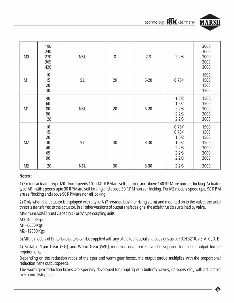
190 3000240 3000
M0 270 NSL 8 2.8 2.2/3 3000365 3000426 3000
10 1500M1 15 SL 20 6-20 0.75/1 1500
20 150030 1500
40 1.5/2 150060 1.5/2 1500
M1 80 NSL 20 6-20 2.2/3 300090 2.2/3 3000120 2.2/3 3000
10 0.75/1 150015 0.75/1 150020 1.5/2 1500
M2 30 SL 30 8-30 1.5/2 150040 2.2/3 300065 2.2/3 300090 2.2/3 3000
M2 120 NSL 30 8-30 2.2/3 3000
Notes :
1) Emtork actuators type M0 - from speeds 10 to 140 RPM are self - locking and above 140 RPM are non self locking. Actuator type M1 - with speeds upto 30 RPM are self locking and above 30 RPM non self locking. For M2 models speed upto 90 RPM are self locking and above 90 RPM are non elf locking.
2) Only when the actuator is equipped with a type A (Threaded bush for rising stem) and mounted on to the valve, the axial thrust is transferred to the actuator. In all other versions of output shaft designs, the axial thrust is sustained by valve.
Maximum Axial Thrust Capacity : For 'A' type coupling units
M0 - 4000 Kgs.M1 - 6000 KgsM2 - 12000 Kgs
3) All the models of Emtork actuators can be supplied with any of the four output shaft designs as per DIN 3210. viz. A, C, D, E.
4) Suitable Spur Gear (SG) and Worm Gear (WG) reduction gear boxes can be supplied for higher output torque requirements.
Depending on the reduction ratios of the spur and worm gear boxes, the output torque multiplies with the proportional reduction in the output speeds.
The worm gear reduction boxes are specially developed for coupling with butterfly valves, dampers etc., with adjustable mechanical stoppers.
technology Germany

The reduction ratios offered are as follows :
GEAR REDUCTION DESIGNATION TYPE OF OUTPUT SHAFTRATIO GEAR BOX TYPE
2.5 : 1 SG02 SPUR GEAR A/C/D/E4 : 1 SG046 : 1 SG068 : 1 SG08
12 : 1 SG12
WORM SPUR TOTAL30 : 1 - 30 : 1 WG030 WORM GEAR E50 : 1 - 50 : 1 WG05075 : 1 - 75 : 1 WG075
100 : 1 - 100 : 1 WG10075 : 1 2.5 : 1 190 : 1 WG200
100 : 1 2.5 : 1 250 : 1 WG250100 : 1 4 : 1 400 : 1 WG400100 : 1 6 : 1 600 : 1 WG700100 : 1 8 : 1 800 : 1 WG1000100 : 1 12 : 1 1200 : 1 WG1500
DATA ON ACTUATOR MOTORS - TYPICAL
Sr. No. Description Motor Output - KW / HP
0.75 / 1 1.5 / 2 2.2 / 3
1. Rated Speed - RPM 1405 1415 28502. Frame Size 80 90 903. Rotor Class KL 16 KL 16 KL 164. Rated current at 415 V - Amps. 1.8 3.3 4.555. Rated torque - mkg. 0.52 1.03 0.7526. Power factor cos ̈ at full load 0.78 0.8 0.837. Efficiency % at full loaf 76 78.5 818. Ratio of current to rated current 4.5 4.8 6.29. Ratio of starting torque to rated torque 3.0 2.5 3.310. Ratio of pull out torque to rated torque 3.25 3.0 3.5
2 211. Ratio GD - Kgm 0.0072 0.016 0.009312. approx weight - Kgs. 11 23 2313. Time allowed at locked rotor - secs. 5 5 514. Stator winding STAR STAR STAR15. Acceleration time with full load connected (Secs.) 3 3 316. Over load capacity for 15 secs. 60% 60% 60%17. Bearings Nos. (Deep Groove Ball Bearings) 6004 6004 620518. Life of Bearings - Hrs. 20,000 20,000 20,00019. Terminal connections (Stud type) Nos. 3 3 320. Earthing terminals 2 2 2
All above motors will have the following Electrical Specifications in commen.
6
technology Germany

7
1. Supply Conditions:
a) 1) Rated voltage - 415 VAC ± 10%2) Rated Frequency - 50 Hz ± 5%3) Combined variation - ± 10%4) No. of Phases - 3 Phase (4 wire)
b) Reference Standards - I. S. 325, IEC34, VDE 0530,BS 2613.
2. Type of motor - TEFC (Totally Enclosed Fan Cooled, Squirrel cage, induction.) / TESC (Totally Enclosed Surface Cooled) for IP 67 / 68
3. Protection - IP 65 as per IS 13947 Part I 1993.
4. Class of Insulation - Class 'F' with temperature rise restricted to class 'B'.
5. Duty cycle - As per IS 325 - S1 continuous (S4 - Modulating as a special case) OR (S2 - 15 / 30 min as a special case.)
6. Method of starting - DOL - Direct on line.
7. Reference ambient temp - 50°c
8. Motor painted with corrosion proof epoxy resin paint.
9. Standard continuous duty ( S1 Duty) motor suitable for:a) 3 Nos. of consecutive starts in hot condition.b) 8 Nos. of starts distributed over 15 minutes.
10. Thermostat for motor protection can be provided as a special accessory.
11. Space heater can be provided as a special accessory.
12. Flame / Explosion proof motors duly approved for Gas groups I, II A, II B & II C as per IS - 2148 are supplied with Flame / Explosion proof actuators, as per requirements.
SPECIFICATION OF TORQUE AND TRAVEL SWITCHES
Description Contract Details Make / Type
Type Rating
Travel Switches 1 NO + 1 NC 10 Amp at Honeywell / Cherry / (MSO /MSE) (change over) 250 VAC equivalent
Micro Switch
Torque Switches 1 NO + 1NC 10 Amp at Siemens / JB / (LSO/LSC) Snap Action 550 VAC Bohmen / Equivalent
Open execution - Limit Switch
Travel / Torque 2 NO + 2 NC 10 Amp at Marsh / JB / BCHSwitches Snap Action 250 VAC
technology Germany

8
SELECTION GUIDE FOR EMTORK ACTUATORS
The steps for selecting the Emtork valve actuator, are as follows:
1. Calculate stem thrust / stem torque necessary foe operating the valve
2. With information on the stem pitch / lead, total number of revolutions required to full open / close the valve and the total operational time, determine the proper speed of the actuator.
3. Depending on the valve - stem design, select suitable out put shaft design of the actuator viz. Type A / C / D / E.
4. Select the suitable accessories as per the requirements.
CALCULATION OF THRUST & TORQUE :
As these factors are governed by the specifications of the fluid handled and material of construction of the valve parts," CALCULATIONS SHOULD BE BASED ON THE VALVE MANUFACTURER'S ACTUAL PERFORMANCE DATA."
A rough calculation method, for a general case, is given below : (To be used as a guideline)
1.1 Lead screw operated valve ( Gate, Globe, Sluice valve etc.)Thrust F=A. Ä P.C. + E ………… Kgs ……………… (1)Torque T = K. F. 1.5 or 2.2…………… mkg (2)
1.5 - when thrust bearing is provided either in valve or in actuator2.2 - when thrust coller is provided in the valve.
WhereA= Cross sectional area of valve port~ ð /4 × (Valve port dia.)²……………cm²P = Max. differential pressure…………………kg/cm²
……………… Generally maximum at fully closed position.……………… Minimum 2 Kgs / cm²
C = Valve factor…………… …………Tabel 1.E = Gland friction allowance - Kgs ……………… Table 2.K = Stem factor ………………… Table 3.
Table 1 Valve Factor (C)
Valve Factor (C)
Valve Type Liquid Gas0 0 0 0Below 400 C Above 400 C Below 400 C Above 400 C
Parallel Side 0.25 0.30 0.35 0.45Wedge Gate 0.35 0.40 0.40 0.50
Globe 1.20 1.20 1.20 1.20
Table 2Gland Friction Allowance (E)
Valve stem diameter Gland friction allowance (E)
Below 25 mm 400 kgs.26 mm - 50 mm 700 kgs51 mm - and above 1100 kgs.
technology Germany

9
Table 3Stem Factor (K)
Lead ofScrew mm Factor (K)
Stem 3 5 6 7 8.5 10 12.5 17 25Dia. mm
19 .0018 .0021 .0023 .0026 .002825 .0022 .0025 .0027 .0028 .0030 .0032 .003632 .0025 .0027 .0030 .0032 .0034 .0036 .004038 .0034 .0036 .0038 .0041 .0045 .004944 .0038 .0041 .0043 .0046 .0049 .005551 .0043 .0046 .0048 .0050 .0053 .0058 .007057 .0047 .0051 .0052 .0055 .0058 .0061 .007464 .0052 .0055 .0056 .0059 .0062 .0066 .007870 .0057 .0059 .0061 .0064 .0067 .0070 .008276 .0061 .0063 .0065 .0068 .0071 .0075 .008683 .0065 .0068 .0070 .0073 .0075 .0079 .009089 .0070 .0072 .0075 .0077 .0080 .0084 .009494 .0075 .0077 .0079 .0082 .0085 .0088 .0098102 .0080 .0082 .0084 .0086 .0087 .0093 .0103108 .0084 .0086 .0088 .0090 .0094 .0097 .0107114 .0088 .0090 .0092 .0095 .0099 .0102 .0112121 .0092 .0094 .0096 .0100 .0104 .0106 .0117127 .0097 .0099 .0100 .0104 .0108 .0110 .0122
Example of Calculation.
Select a suitable Emtork actuator for the following conditions.300 mm wedge gate, non - rising stem valve, stem dia. 44 mm. 8.5 mm pitch, to operate in approx.
21 minute, on 14 kgs / cm differential pressure. (Fluid inside, water at normal temperature.) Thrust bearing provided in the valve. Total revolutions required for full opening / closing of valve = 40.
1. Thrust F = (A. P.C.) + E= (706.5 x 14 x 0.35) + 700= 4162 kgs.
2. Torque T = F x K= 4162 x 0.0043 x 1.5= 26.1 mkg - Hence M1 actuator with SG02 (gear ratio 2.5 : 1) will be required.
3. Total revolution required to full open / close valve = 40 Hence the actuator output rev. required = 40 x 2.5 = 100 to operate the valve in 1 minute.
4. Therefore, the recommended Emtork model - M1 / 090 / SG02 / WG000 / E (effective operating time will be 1.1 min.)
55
technology Germany
10
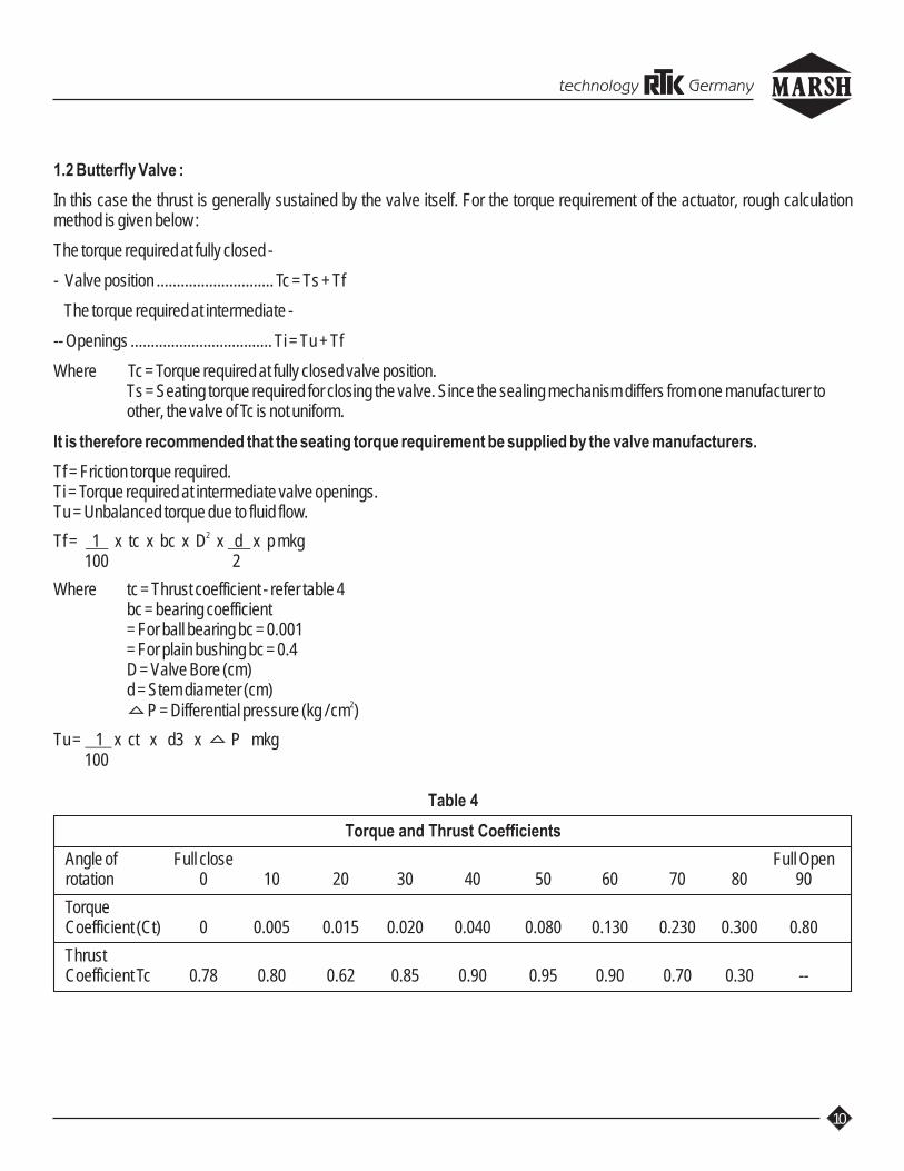
1.2 Butterfly Valve :
In this case the thrust is generally sustained by the valve itself. For the torque requirement of the actuator, rough calculation method is given below :
The torque required at fully closed -
- Valve position ............................. Tc = Ts + Tf
The torque required at intermediate -
-- Openings ................................... Ti = Tu + Tf
Where Tc = Torque required at fully closed valve position.Ts = Seating torque required for closing the valve. Since the sealing mechanism differs from one manufacturer toother, the valve of Tc is not uniform.
It is therefore recommended that the seating torque requirement be supplied by the valve manufacturers.
Tf = Friction torque required.Ti = Torque required at intermediate valve openings.Tu = Unbalanced torque due to fluid flow.
2Tf = 1 x tc x bc x D x d x p mkg 100 2
Where tc = Thrust coefficient - refer table 4bc = bearing coefficient= For ball bearing bc = 0.001= For plain bushing bc = 0.4D = Valve Bore (cm)d = Stem diameter (cm)
2P = Differential pressure (kg / cm )
Tu = 1 x ct x d3 x P mkg 100
Table 4
Torque and Thrust Coefficients
Angle of Full close Full Openrotation 0 10 20 30 40 50 60 70 80 90
TorqueCoefficient (Ct) 0 0.005 0.015 0.020 0.040 0.080 0.130 0.230 0.300 0.80
ThrustCoefficient Tc 0.78 0.80 0.62 0.85 0.90 0.95 0.90 0.70 0.30 --
5
5
5
5
technology Germany

Example of Calculations :
Select a suitable "Emtork" valve actuator for the following conditions :2A tight seat Butterfly valve size 500 mm diameter, stem diameter 60 mm, differential pressure at full closed position 3 kg / cm at
080 opening.Calculations :
Ts = 30 mkg (Assumed for a particular valve manufacturer)2Tf at full closed position = 1 x tc x bc x D x d x p mkg
100 22= 1 x 0.78 x 0.4 x 50 x 6 x 3 mkg
100 2= 70 mkg
0 2Tf at 80 opening = 1 x 0.3 x 0.4 x 50 x 6 x 0.2 mkg 100 2= 1.8 mkg
0 3Tu at 80 opening = 1 x 0.3 x 50 x 0.2 mkg 10= 75 mkg
Therefore,The total torque required at full close is,
Tc = Ts + Tf = 30 + 70 = 100 mkg
0The total torque required at 80 opening is,Ti = Tu + TfTi = 75 + 1.8 = 76.8
Hence a suitable actuator have to be selected for 100 mkg output torque.Therefore, the recommended 'Emtork' model : M1 / 010 / SG00 / WG030 / E
0(Operating time for 90 travel - 45 Secs.)
Conversion Table - 1
mkgs ft-lbs mkgs ft-lbs mkgs ft-lbs
1 7.233 15 108.495 65 470.145
2 14.466 20 144.660 70 506.310
3 21.699 25 180.825 75 542.475
4 28.932 30 216.990 80 578.640
5 36.165 35 253.135 85 614.805
6 43.398 40 289.320 90 650.970
7 50.631 45 325.485 95 687.135
8 57.864 50 361.650 100 723.300
9 65.097 55 397.815
10 72.330 60 433.980
11
technology Germany
12
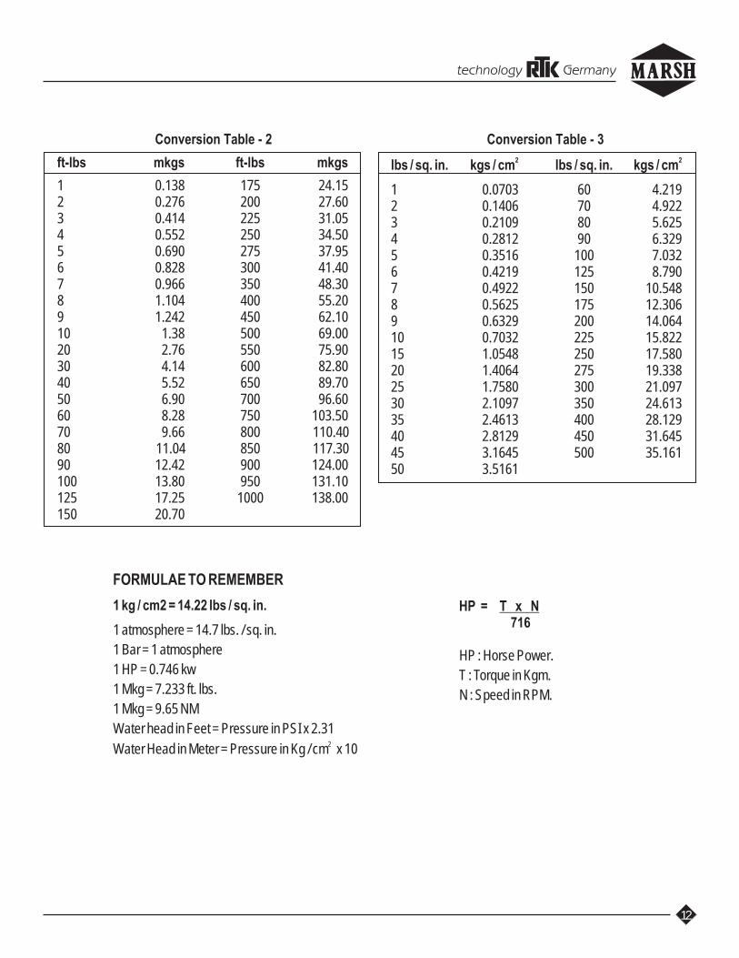
Conversion Table - 2
ft-lbs mkgs ft-lbs mkgs
1 0.138 175 24.152 0.276 200 27.603 0.414 225 31.054 0.552 250 34.505 0.690 275 37.956 0.828 300 41.407 0.966 350 48.308 1.104 400 55.209 1.242 450 62.1010 1.38 500 69.0020 2.76 550 75.9030 4.14 600 82.8040 5.52 650 89.7050 6.90 700 96.6060 8.28 750 103.5070 9.66 800 110.4080 11.04 850 117.3090 12.42 900 124.00100 13.80 950 131.10125 17.25 1000 138.00150 20.70
Conversion Table - 3
2 2lbs / sq. in. kgs / cm lbs / sq. in. kgs / cm
1 0.0703 60 4.2192 0.1406 70 4.9223 0.2109 80 5.6254 0.2812 90 6.3295 0.3516 100 7.0326 0.4219 125 8.7907 0.4922 150 10.5488 0.5625 175 12.3069 0.6329 200 14.06410 0.7032 225 15.82215 1.0548 250 17.58020 1.4064 275 19.33825 1.7580 300 21.09730 2.1097 350 24.61335 2.4613 400 28.12940 2.8129 450 31.64545 3.1645 500 35.16150 3.5161
FORMULAE TO REMEMBER
1 kg / cm2 = 14.22 lbs / sq. in.
1 atmosphere = 14.7 lbs. / sq. in.
1 Bar = 1 atmosphere
1 HP = 0.746 kw
1 Mkg = 7.233 ft. lbs.
1 Mkg = 9.65 NM
Water head in Feet = Pressure in PSI x 2.312Water Head in Meter = Pressure in Kg / cm x 10
HP = T x N 716
HP : Horse Power.
T : Torque in Kgm.
N : Speed in RPM.
technology Germany
13
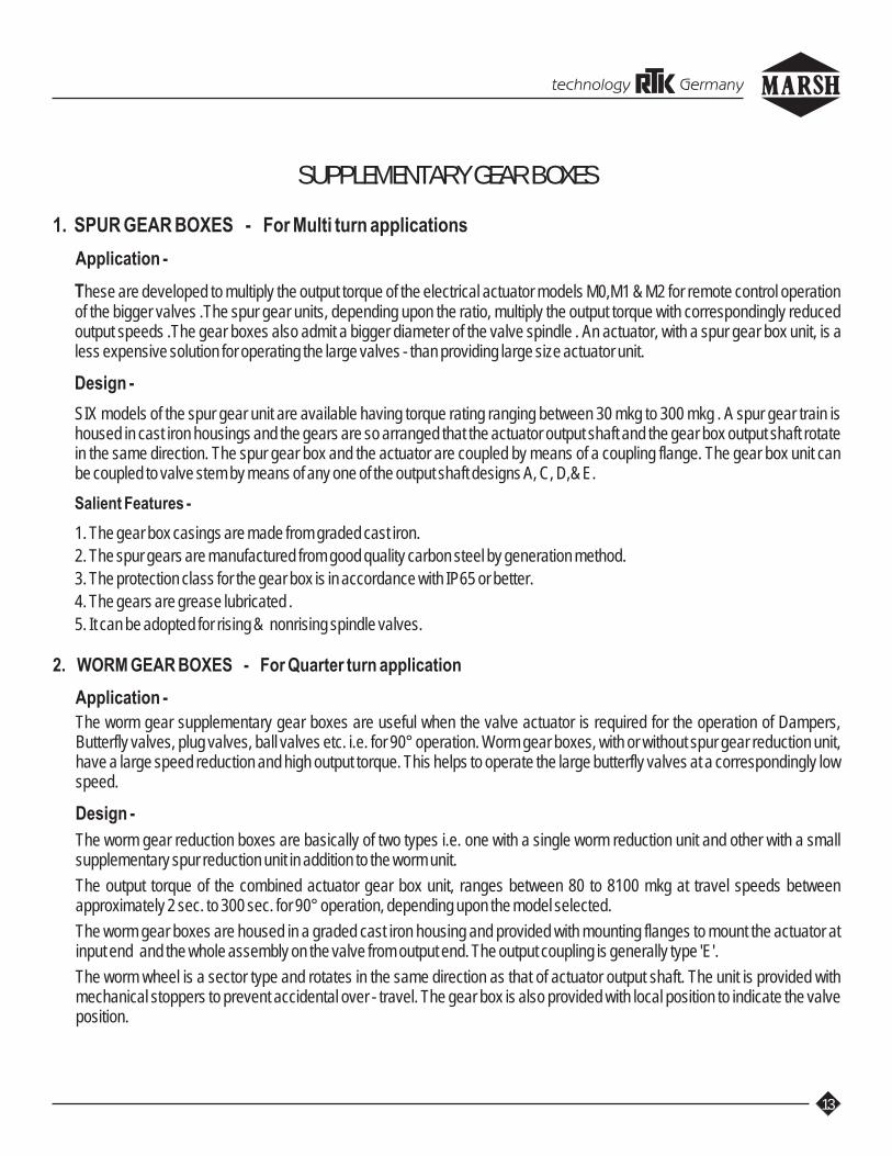
SUPPLEMENTARY GEAR BOXES
1. SPUR GEAR BOXES - For Multi turn applications
Application -
These are developed to multiply the output torque of the electrical actuator models M0,M1 & M2 for remote control operation of the bigger valves .The spur gear units, depending upon the ratio, multiply the output torque with correspondingly reduced output speeds .The gear boxes also admit a bigger diameter of the valve spindle . An actuator, with a spur gear box unit, is a less expensive solution for operating the large valves - than providing large size actuator unit.
Design -
SIX models of the spur gear unit are available having torque rating ranging between 30 mkg to 300 mkg . A spur gear train is housed in cast iron housings and the gears are so arranged that the actuator output shaft and the gear box output shaft rotate in the same direction. The spur gear box and the actuator are coupled by means of a coupling flange. The gear box unit can be coupled to valve stem by means of any one of the output shaft designs A, C, D,& E.
Salient Features -
1. The gear box casings are made from graded cast iron.
2. The spur gears are manufactured from good quality carbon steel by generation method.
3. The protection class for the gear box is in accordance with IP65 or better.
4. The gears are grease lubricated .
5. It can be adopted for rising & nonrising spindle valves.
2. WORM GEAR BOXES - For Quarter turn application
Application -
The worm gear supplementary gear boxes are useful when the valve actuator is required for the operation of Dampers, Butterfly valves, plug valves, ball valves etc. i.e. for 90° operation. Worm gear boxes, with or without spur gear reduction unit, have a large speed reduction and high output torque. This helps to operate the large butterfly valves at a correspondingly low speed.
Design -
The worm gear reduction boxes are basically of two types i.e. one with a single worm reduction unit and other with a small supplementary spur reduction unit in addition to the worm unit.
The output torque of the combined actuator gear box unit, ranges between 80 to 8100 mkg at travel speeds between approximately 2 sec. to 300 sec. for 90° operation, depending upon the model selected.
The worm gear boxes are housed in a graded cast iron housing and provided with mounting flanges to mount the actuator at input end and the whole assembly on the valve from output end. The output coupling is generally type 'E'.
The worm wheel is a sector type and rotates in the same direction as that of actuator output shaft. The unit is provided with mechanical stoppers to prevent accidental over - travel. The gear box is also provided with local position to indicate the valve position.
technology Germany

14
Salient Features -
1. The worm shaft is manufactured from good quality carbon steel.The worm is made from alloy steel and is precisely cut to match the worm wheel. It is supported on two bush bearings.
2. The worm wheel, which is of sector type, is made from Ph. Bronze/ S. G. Iron and is precisely hobbed to give maximum efficiency.
3. The protection class for the gear box is in accordance with IP65 or better.
4. The gears are lubricated with grease while assembling.
5. The gear box is provided with thrust bearings to take end thrust during operation.
NOTES :
1. The auxiliary gear boxes are basically used to increase the output torque, which is necessary while operating bigger/ high pressure valves. By coupling the auxiliary gear box to the actuator, the effective output speed reduces due to which the operation time for valve closing / opening increases.
2. By coupling the spur gear box to the actuator the output motion of the combined unit remains rotary only : whereas by 0coupling the actuator to the worm gear boxes, the output motion gets restricted only to quarter turn (90 ). Hence, the spur
gear box combination is suitable only for those valves which require rotary motion for closing / opening (e.g. gate, sluice 0 valves etc.) and the worm gear box combination is suitable only those valves which require 90 (quarter turn) opening /
closing (e.g. Butterfly valves, dampers etc.)
3. The output speeds and torques of the possible combined units are given in the following tables.
4. It may be noted that both the spur and worm gear boxes cannot be coupled to the actuator at one time, except the ones recommended by us.
5. If the output speed of the combined unit does not match with the standard output speeds mentioned in the catalogue and if lower output speed of the actuator is required you may please refer back to us as we may be able to offer different output speeds by changing the gear ratios in the actuator, if possible.
6. It is possible to offer different output shaft designs viz. A / C / D / E of the combined unit of actuator and spur gear box, depending on the valve requirements.
7. When the actuator is coupled to the worm gear box, the combined unit is suitable only for butterfly valves or dampers where shaft design type 'E' is suitable.
8. When actuator is to be coupled to any type of auxiliary gear boxes (spur or worm) the output shaft design "of the actuator" has been standardised of type 'E' only.
9. For selecting the output shaft design of the bare actuator and spur gear combination, the following points have to be taken into consideration :
a) For rising stem valves, only output shaft design A & C will be suitable as the rising stem of the valve will pass through the body of the actuator / gear box. The diameter of the stem of the valve has to be maximum upto 28 mm while using M0 model and 36 mm while using M1 model and 52 for M2, as the stem has to clearly pass through the holes give in the actuator body as shown in the catalogue. If the actuator is coupled with the spur gear box the maximum stem dia will be as specified in the gear - box selection chart.
b) Most commonly used output shaft design is type 'E' where male part of the valve stem is fixed by means of key to the actuator.
technology Germany

15
'EMTORK'
Flameproof / Explosion proof Actuators
APPLICATION : 'Emtork' - actuators are the high output torque at high speed units and designed for the remote control and regulation of valves in the hazardous locations.
These actuators can be used to operate gate valves, globe valves, butterfly valves, sluice valves and such similar equipment.The actuator is designed to ensure that in a hazardous location any accidental internal explosion is contained in the flameproof enclosure without damage to itself and without communicating the flammation (or explosion) to the external hazardous atmosphere.
CERTIFICATION : 'Emtork' flameproof actuator has been tested and certified by Central Mining Research Station (CMRS, Dhanbad) for Group I, IIA and IIB, locations as per IS:2148 - 1981. The actuators have also been approved by the Directorate General, Factory Advice Service and Labour Institute, Bombay.
CONSTRUCTION : The basic actuators follow the design of M0 and M1 models and have the features specified in our catalogue. The CMRS certification covers Actuators Type M0 and M1 with SG (Spur Gear) and WG (Worm Gear) type Auxiliary Gear Boxes. The actuators are coupled with Flame proof motors.
'EMTORK'
Linear Actuator - Model LMO / 75 & LM1 / 100
DESCRIPTION : This linear model is built around 'EMTORK' Rotary actuator, model M0 with a rated output torque of 8 mkg. & M1 with 20 mkg.
The Linear actuator Model LM0 / 75 gives a max. Thrust of 3500 kgs. (rated thrust 3000 kgs.) and a stroke of 75 mm. LM1 / 100 gives max Thrust of 4500 kgs. (rated thrust 4000 kgs.) and a stroke of 100 mm. Variety of linear speeds are available, depending upon the basic M0 & M1 actuator chosen.
TECHNICAL DATA :
LM0 LM1Max. stroke 75 mm 100 mmRated thrust 3000 kgs. 4000 kgs.Max. thrust 3500 kgs. 4500 kgs.Degree of Protection IP 65 IP 65Weight 78 kgs. 88 kgs.Stroke Adjustment 10 to 75 mm 10 to 100 mmLinear Speed - As per the enclosed chartMotor Data - As per our Catalogue
technology Germany

a = ---- stroke
1
2
x = ---------
a0sin 45
16
SPECIFICATIONS OF LINEAR ACTUATORS - MODELS : LM0 / 75 & LM1 / 100
MODELS.N. LM0/75 LM1/100
Act. Linear Motor Act. Linear MotorSpeed Speed Speed SpeedRPM mm/sec KW RPM RPM mm/sec KW RPM
01. 10 1 0.75 1395 10 1 0.75 139502. 15 1.5 0.75 1395 15 1.5 0.75 139503. 20 2 0.75 1395 20 2 0.75 139504. 30 3 0.75 1395 30 3 0.75 139505. 40 4 0.75 1395 40 4 1.5 139506. 60 6 0.75 1395 60 6 1.5 139507. 80 8 2.2 2850 90 9 2.2 285008. 120 12 2.2 2850 120 12 2.2 285009. 190 19 2.2 2850 -- -- -- --10. 270 27 2.2 2850 -- -- -- --11. 360 36 2.2 2850 -- -- -- --
Emtork Damper Actuators - TM Services
Applications :
1. These are units basically a combination of Emtork actuator with supplementary worm gear box duly mounted on 0mounting brackets and coupled with a suitable linkages to convert quarter turn (90 ) movement into a linear one for the
operation of dampers, flaps, gates etc.2. These actuators are selected considering following factors.a) Total thrust required in kgs.b) Length of the stroke in mm.c) Speed of operation mm/sec.
(Refer Diagrams TM1 - 01 R1, Tm1 - 02 and tables TM1 - 03, TM1 - 04 and TM1 - 05 for details)
Table TM1 - 030LENGTH OF ARM (for 90 travel of arm corresponding to various stroke length) - Series TM
Sr. no. Length of stroke Length of arm Strokemm mm
1 150 1062 200 1413 300 2124 400 2835 500 3546 600 4247 700 4958 800 5669 900 63610 1000 707
a
x
045
a
x x = Length of Arm.0Sin 45 = 0.707
The thrust is calculated as follows :Thrust = ------------------------------------
Torque in mkg
Length of arm in meters
technology Germany

Tab
le T
M1
- 4
DE
TAIL
S O
F T
HR
US
T A
ND
ST
RO
KE
VA
LU
ES
OF
LIN
EA
R A
CT
UA
TOR
- S
erie
s T
M
Sr.
Str
oke
No
.L
eng
thM
od
elM
od
elM
od
elM
od
elM
od
elm
mT
M0
/ - /
WG
030
TM
1 / -
/ W
G03
0T
M1
/ - /
WG
050
TM
1 / -
/ W
G07
5T
M1
/ - /
WG
100
1.15
013
5 to
540
540
to 1
800
900
to 3
000
1350
to 4
500
1800
to 6
000
2.20
010
0 to
400
400
to 1
400
700
to 2
300
1050
to 3
500
1400
to 4
650
3.30
067
to 2
7027
0 to
900
450
to 1
500
675
to 2
250
900
to 3
000
4.40
050
to 2
0020
0 to
700
350
to 1
150
525
to 1
750
700
to 2
325
5.50
040
to 1
6016
0 to
550
270
to 9
0040
0 to
137
554
0 to
180
0
6.60
034
to 1
3513
5 to
450
225
to 7
5034
0 to
112
545
0 to
150
0
7.70
030
to 1
2012
0 to
400
200
to 6
5030
0 to
100
040
0 to
130
0
8.80
025
to 1
0010
0 to
350
170
to 5
7526
0 to
875
340
to 1
165
9.90
022
to 9
090
to 3
0015
0 to
500
225
to 7
5030
0 to
100
0
10.
1000
20 to
80
80 to
275
135
to 4
5020
0 to
680
270
to 9
00
DE
TAIL
S O
F O
UT
PU
T S
PE
ED
FO
R L
INE
AR
AC
TU
ATO
R -
Ser
ies
TM
Lin
ear
ou
tpu
t sp
eed
s m
m /
sec.
(ap
pro
x.)
Sr.
Act
uat
or
Bas
ic10
1520
3040
6080
9012
018
027
0N
o.
Mo
del
sA
ctu
ato
rS
pee
ds
RP
M
1.T
M0
/ - /
WG
030
35
710
1420
25--
3860
88
2.T
M1
/ - /
WG
030
35
710
1420
--30
----
--
3.T
M1
/ - /
WG
050
23
46
812
--19
----
--
4.T
M1
/ - /
WG
075
1.3
23
45
8--
12--
----
5.T
M1
/ - /
WG
100
11.
52
34
6--
9--
----
tech
nolo
gy G
erm
any
17
18
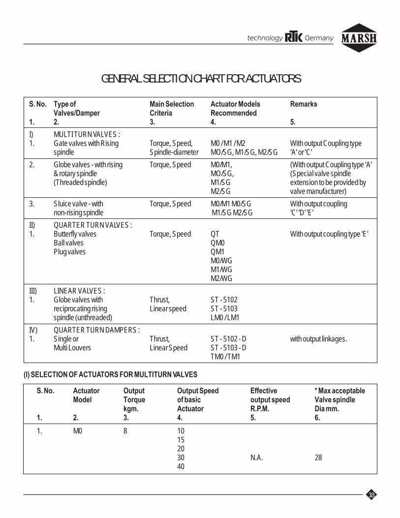
GENERAL SELECTION CHART FOR ACTUATORS
S. No. Type of Main Selection Actuator Models RemarksValves/Damper Criteria Recommended
1. 2. 3. 4. 5.
I) MULTI TURN VALVES :1. Gate valves with Rising Torque, Speed, M0 / M1 / M2 With output Coupling type
spindle Spindle-diameter MO/SG, M1/SG, M2/SG 'A' or 'C'
2. Globe valves - with rising Torque, Speed M0/M1, (With output Coupling type 'A'& rotary spindle MO/SG, (Special valve spindle(Threaded spindle) M1/SG extension to be provided by
M2/SG valve manufacturer)
3. Sluice valve - with Torque, Speed M0/M1 M0/SG With output couplingnon-rising spindle M1/SG M2/SG 'C' 'D' 'E'
II) QUARTER TURN VALVES :1. Butterfly valves Torque, Speed QT With output coupling type 'E'
Ball valves QM0Plug valves QM1
M0/WGM1/WGM2/WG
III) LINEAR VALVES :1. Globe valves with Thrust, ST - 5102
reciprocating rising Linear speed ST - 5103spindle (unthreaded) LM0 / LM1
IV) QUARTER TURN DAMPERS :1. Single or Thrust, ST - 5102 - D with output linkages.
Multi Louvers Linear Speed ST - 5103 - DTM0 / TM1
(I) SELECTION OF ACTUATORS FOR MULTITURN VALVES
S. No. Actuator Output Output Speed Effective * Max acceptableModel Torque of basic output speed Valve spindle
kgm. Actuator R.P.M. Dia mm.1. 2. 3. 4. 5. 6.
1. M0 8 10152030 N.A. 2840
technology Germany

19
1. 2. 3. 4. 5. 6.
607080120140 N.A. 28190240270365426
2. M1 20 101520 3630 N.A.40608090120
3. M2 30 10152030 N.A. 52406590120
4. M0/SG02 16 10 4(2:5:1) 15 6 52
â â360 144
5. M1/SG02 40 10 4(2:5:1) 15 6 52
â â120 48
6. M1/SG04 65 10 2.5(4:1) 15 3.75 55
â â120 30
technology Germany

20
1. 2. 3. 4. 5. 6.
7. M1/SG06 100 10 1.7(6:1) 15 2.5 60
â â120 20
8. M1/SG08 130 10 1.25(8:1) 15 1.9 80
â â120 15
9. M1/SG12 200 10 0.8(12:1) 15 1.25 90
â â120 10
10. M2/SG12 300 10 0.8 100(12:1) â â
120 10
Note :
1) * Max. acceptable valve spindle diameter applicable only for rising spindle valves Actuator output shaft design 'A' or 'C'
2) Output speed of basic actuatorEffective output speed = ----------------------------------------
Gear Reduction Ratio
3. Ordering Specification : M
Basic Actuator M0M1M2
Output Speed of basic actuator
Spur gear box type
Worm gear box
Output shaftdesign of spurgear box viz. A, C, D, E.
S G W G 0 0 0
technology Germany
21
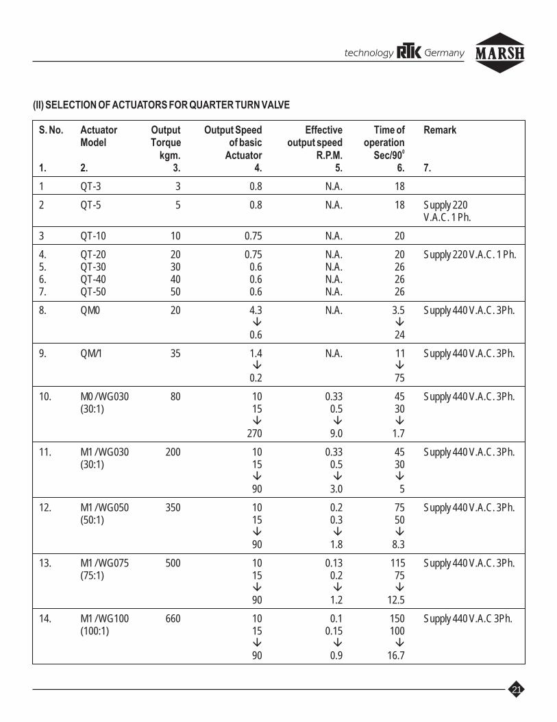
(II) SELECTION OF ACTUATORS FOR QUARTER TURN VALVE
S. No. Actuator Output Output Speed Effective Time of RemarkModel Torque of basic output speed operation
0kgm. Actuator R.P.M. Sec/901. 2. 3. 4. 5. 6. 7.
1 QT-3 3 0.8 N.A. 18
2 QT-5 5 0.8 N.A. 18 Supply 220V.A.C. 1 Ph.
3 QT-10 10 0.75 N.A. 20
4. QT-20 20 0.75 N.A. 20 Supply 220 V.A.C. 1 Ph.5. QT-30 30 0.6 N.A. 266. QT-40 40 0.6 N.A. 267. QT-50 50 0.6 N.A. 26
8. QM0 20 4.3 N.A. 3.5 Supply 440 V.A.C. 3Ph.â â
0.6 24
9. QM/1 35 1.4 N.A. 11 Supply 440 V.A.C. 3Ph.â â
0.2 75
10. M0 / WG030 80 10 0.33 45 Supply 440 V.A.C. 3Ph.(30:1) 15 0.5 30
â â â270 9.0 1.7
11. M1 / WG030 200 10 0.33 45 Supply 440 V.A.C. 3Ph.(30:1) 15 0.5 30
â â â90 3.0 5
12. M1 / WG050 350 10 0.2 75 Supply 440 V.A.C. 3Ph.(50:1) 15 0.3 50
â â â90 1.8 8.3
13. M1 / WG075 500 10 0.13 115 Supply 440 V.A.C. 3Ph.(75:1) 15 0.2 75
â â â90 1.2 12.5
14. M1 / WG100 660 10 0.1 150 Supply 440 V.A.C 3Ph.(100:1) 15 0.15 100
â â â90 0.9 16.7
technology Germany

22
1. 2. 3. 4. 5. 6. 7.
15. M1 / WG200 1050 10 0.05 300 Supply 440 V.A.C. 3Ph.(190:1) 15 0.08 187
â â â90 0.47 31.90
16. M1 / WG250 1400 10 0.04 375 Supply 440 V.A.C. 3Ph.(250:1) 15 0.06 250
â â â90 0.36 41.7
17. M1 / WG400 2400 10 0.025 600 Supply 440 V.A.C. 3Ph.(400:1) 15 0.037 405
â â â90 0.225 66.7
18. M1 / WG1000 5400 10 0.010 1500 Supply 440 V.A.C. 3Ph.(800:1) 15 0.016 937
â â â90 0.094 159.6
19. M1 / WG1500 8100 10 0.007 2143 Supply 440 V.A.C. 3 Ph.(1440:1) 15 0.01 1500
â â â90 0.062 242
Note :
1) Output speed of basic actuatorEffective output speed = ---------------------------------------
Reduction Ratio of Gear Box
2) Ordering Specification : M W G E
Basic Actuator M0M1
Output Speed ofbasic actuator
Worm gear box type
technology Germany

23
(III) SELECTION OF ACTUATORS FOR LINEAR VALVES
S. No. Actuator Output Output Speed Linear Max. Stroke RemarksModel Thrust of basic Actuator output speed Length
kgs. R.P.M. mm/sec. mm1. 2. 3. 4. 5. 6. 7.
1 ST-5102 200 N.A. 0.26 43 Supply 220 V.A.C. 1Ph.
2 ST-5103 600 N.A. 0.45 60 Supply 220 V.A.C. 1Ph.
3 LM0 3000 10 1 75 Supply 440 V.A.C. 3Ph.15 1.5â â360 36
4 LM1 4000 10 1 Supply 440 V.A.C. 3Ph.15 1.5 100â â120 12
NOTE :
1) In case of LM0 actuator the output spindle moves by 6 mm per revolution. Hence Linear output speedOutput R.P.M. x 6
mm / sec. = ------------------------- 60
2) Ordering Specifications :i) Regeltek Actuators : ST - 5102
ST - 5103
ii) Emtork Actuator L
Basic Actuator M0M1
Mention output speedof the basic actuatorR.P.M.
Stroke 75100
technology Germany

24
IV) SELECTION OF ACTUATORS FOR QUARTER TURN DAMPERS
S. No. Actuator Output Length of Output Speed Effective LinearModel Thrust Stroke of basic Actuator Output speed
kg. (Rated) mm R.P.M. mm/sec.1. 2. 3. 4. 5. 6.
1. ST - 5102 - D 40 180 N.A. 1.3
2. ST - 5103 - D 85 400 N.A. 3.2
3. TM0 / WG030 540 150 10 3200 200 15 5â â â â80 1000 270 88
4. TM1 / WG030 1800 150 10 31400 200 15 5â â â â
275 1000 90 30
5. TM1 / WG050 3000 150 2 102300 200 3 15â â â â
450 1000 19 90
6. TM1 / WG075 4500 150 1.3 103500 200 2 15â â â â
680 1000 12 90
7. TM1 / WG100 6000 150 1 104650 200 1.5 15â â â â
900 1000 9 90
NOTE : Ordering Specifications :i) Regeltek Units : ST - 5102 - D
ST - 5103 - D
ii) Emtork Units : T W G
Actuator : M0M1
Output speed of basic actuator
Worm gear Box
technology Germany

MOUNTING FLANGE
DIMENTIONS
MARSH ENGINEERS
SCALE NTS TITLE- DRG.NO.
SHEET 1 OF 1
GEN 704
4
4
4
4
8
8
8
8
OR BOLTSOF STUDS
NUMBER
M20130 165F 16 210
415
350
300
475F 40
F 30
F 25
F 35 356
298
254
406300
230
200
260
M36
M20
M30
M16
Ø D1
125
90
175
F 10
F 07
F 14
TYPEFLANGE Ø D3
102
140
70
55
100
70
Ø D2
M10
M16
M8
Ø D4
Note 1 - The method of attachment may be by means of studs or through bolting When the later method is used, the diameter of the clearance holes shall permit the use of bolts of a size given by the corresponding D4 dimensions.
Note 2 - The holes for the studs/bolts shall be located off-centre and shall be equispaced.
Note 3 - The recess in the mounting surface corresponding to diameter, D2, is mendatory ; the spigot on the actuator is optional.
Note 4 - The dimension, D1, has been based on sufficient landing for the nuts and bolts heads, where applicable. Such landing is defined as a radius from the bolt hole centre with the dimension (D1-D3) / D2, and shall be considered as a minimum. The shape of the flange of both valve and actuator outside of these areas of landing is left to the option of the manufacturer.
Ø D4
Ø D1
Ø D3
Ø D2
Ø D4
ACTUATOR

190
170
190
170
OV
ER
AL
L D
IME
NS
ION
S O
F E
MTO
RK
AC
TU
ATO
RS
MO
DE
LS
MO
& M
1-A
S P
ER
IS 9
334-
1986
220
310
8543
6
450
340 Onl
y fo
r M
O
VIE
W F
RO
M P
Onl
y fo
r M
1
M8x
4H
P
10 D
EE
P
Ø 4
85
TY
PE
-A
bush
for
risin
g st
em
With
thre
aded
MO
DE
L M
0, M
1 &
M2
OU
TP
UT
SH
AF
T D
ES
IGN
S (
AS
PE
R D
IN 3
210)
EM
TOR
K E
LE
CT
RIC
AC
TU
ATO
RS
DIM
EN
TIO
NS
M1
M2
TY
PE
M0
Ø d
9
H8
100
100
8 8
208
208
175
175
36 52
M16
M16
30 30
30 30
Ø d
2
70f8Ø
d1
H9 6
P9
H11 14
612
5
b4b3
b2d3
max
.
28M
10
g6 2020
Ø d
5Ø
d8
12 12
55 55
6K 12K
22 22
4 4
70 70
140
140
7626
7626
76 76
h3 10
h2h1
gm
ax.
40
kg.
4K15
3
FL6
t2L4
L5P
CD
5010
255
16.5
55
Ø k
70 75
33.3
33.3
F14
F14
Mou
ntin
gt3
Wei
ght
Kg. 52
22.8
F10
App
.
for
nonr
isin
gst
em
With
sha
ftT
YP
E-D
exte
ntio
n
Ø d
5 m
ax.
Ø d
2
h2
d3g h1
Ø k
Ø d
1F
-MA
X.
*+....
-4 H
oles
-Off
cent
re.
F-M
ax-M
axim
un A
xial
Thu
rst.
+....*
coup
ling
stem
for
risin
g / n
onris
ing
With
cla
w
TY
PE
-C
for
nonr
isin
gst
em
TY
PE
-EW
ith b
ore
& k
ey
L4
L5
b3
Ø d
8
t2
h3
b2
L6
t3
b4
Ø d9
OVE
RA
LL D
IMEN
TIO
NS
FOR
EM
TOR
K A
CTU
ATO
RS
MA
RS
H E
NG
INE
ER
S
TIT
LE-
DR
G.N
O.
SH
EE
T 1
OF
1
GE
N 7
56
AP
PLI
CA
BLE
ON
LY IN
CA
SE
OF
UN
IT W
ITH
INT
EG
RA
L S
TAR
TE
R &
PO
SIT
ION
ER
.
*
A :
20
5mm
WIT
H P
OS
ITIO
NE
R U
NIT
.
:
120
mm
WIT
HO
UT
PO
SIT
ION
ER
UN
IT.
Ø 3
0H8x
75 D
EE
P W
ITH
KE
YW
AY
8Wx3
.3 D
EE
P -
TY
PE
E C
OU
PLI
NG
.
LOC
AL
IND
ICAT
OR
MO
TOR
LOC
AL
PU
SH
BU
TTO
NS
CA
BLE
GLA
ND
SM
OU
NT
ING
SID
E
CLU
TC
H L
EV
ER
HA
ND
WH
EE
L
Ø 1
00f8
PO
SIT
ION
ER
330
540
180 130230 A
Ø 245
Ø 1
80
Ø 1
82
480
**
**4H
M16
x20D
EE
P
AT 1
40 P
CD
-OF
F C
EN
TR
E.-
F14
-MO
UN
TIN
GØ
175
CU
STO
ME
RC
ON
NE
CT
ION
S
++.... ..
..
183
357
Ø 4
40
.. .
. ...
.
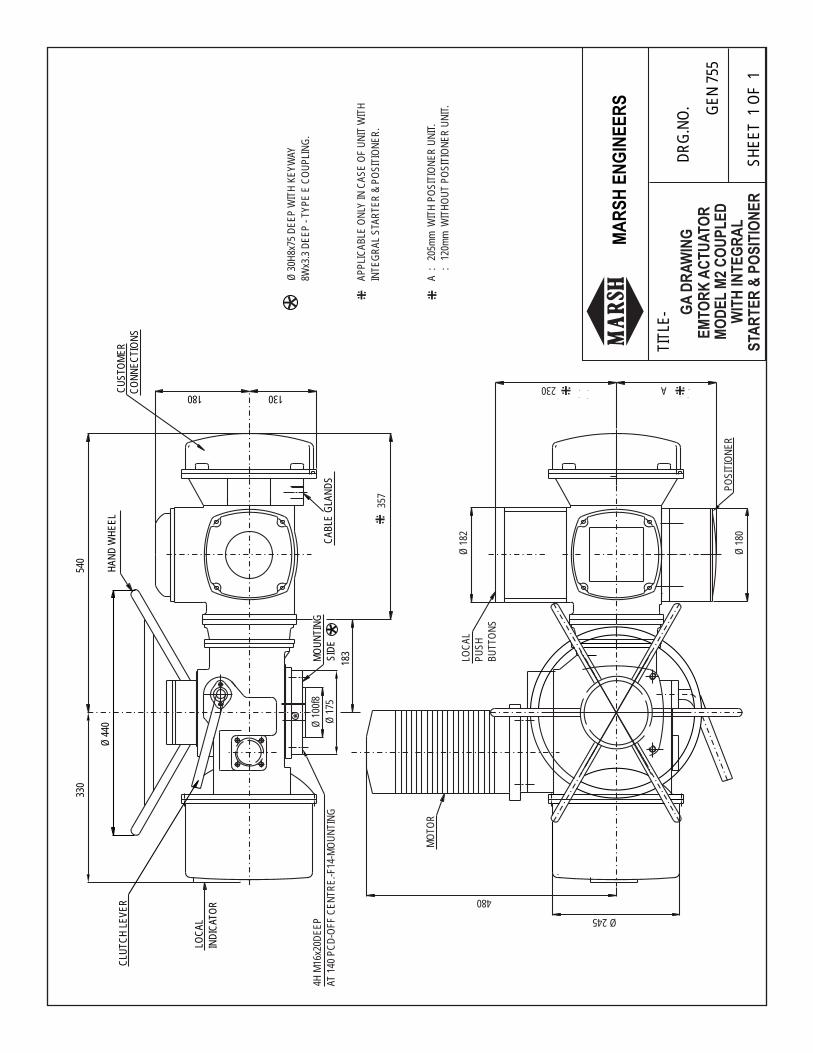
WIT
H IN
TE
GR
AL
EM
TOR
K A
CT
UA
TOR
MO
DE
L M
2 C
OU
PL
ED
GA
DR
AW
ING
STA
RT
ER
& P
OS
ITIO
NE
R
MA
RS
H E
NG
INE
ER
S
TIT
LE-
DR
G.N
O.
SH
EE
T 1
OF
1
GE
N 7
55
++.... ..
.. ++.... ..
..
++.... ..
..++.... ..
..


4H-M
20x2
5L
8H-M
16x2
0L
8H-M
20x2
5L
8H-M
16x2
0L
4H-M
20x2
5L
SG
12
SG
08
SG
04
SG
06
SG
02
f off-
cent
re
210
TY
PE
SG
12
300
254
SG
06
SG
08
SG
04
165
210
210
165
165
120
60S
G 1
2
SG
02
TY
PE
210
165
d1d2
SG
08
SG
06
5011
0
5011
0
100
160
606
25
5013
0
130
50
130
40
620
620
525
130
64.4
18
53.8
120
120
53.8
43.3
14 1412
1864
6 130
40
d3d4
525
el1
653
.5
653
.5
1414
100
43.3
l2t1
12b1
100
64S
G 0
6
SG
02
SG
04
TY
PE
9040 40
90
d5l3
SG
12
SG
08
7512
0
6410
0
SG
04
SG
02
6410
0
6410
0
TY
PE
d6d7
1630
435 5
43
h2t2
12 12b2
4018
3016
3016
3016
gh
Ø33
0 F
OR
EX
TR
A L
ON
G R
ISIN
G S
TE
M.
ED
BN
O.
SIZ
E
Ø48
5 F
OR
NO
RM
AL
AP
PLI
CAT
ION
.
165
695
580
3S
G 0
6
ØF
5S
G 1
2
4S
G 0
8
725
615
200
695
580
165
2S
G 0
4
1S
G 0
2
670
560
142
M1
670
560
M0
142
244
490
720
183
380
604
190
210
380
258
610
530
180
258
500
SR
.A
C
440
MA
X.
Ø F
685
MA
X.
C
A
B
f
Ø d
1Ø
d2
l2
TY
PE
-'E'
l1
Ø d
3f8
e
Ø d
4H8
t1
b1P
9
h2
TY
PE
-'D'
Ø d
5h8
l3
t2
b2h8
TY
PE
-'C'
h1
d6d7
g
525
523
0S
G 0
880
8xM
16x2
80P
CD
SG
12
ON
DE
MA
ND
330
SG
04
SG
02
SG
06
TY
PE
4xM
20x1
90P
CD
4xM
20x2
10P
CD
4xM
20x2
10P
CD
185
150
255
140
5223
0
165
230
6055
330
250
f8ø d
1ø
dø
d2
L
55
MO
UN
TIN
G H
OLE
SF 5
OF
F-C
EN
TR
E
231
D
E
SP
IND
LE
RIS
ING
FO
R
CA
P
GE
AR
(SG
) B
OX
ES
AC
TU
ATO
R W
ITH
SP
UR
EM
TOR
K V
ALV
EMA
RS
H E
NG
INE
ER
S
TIT
LE-
DR
G.N
O.
SH
EE
T 1
OF
1
GE
N 7
19
Ø d
2
Ø d
1
TY
PE
-'A'
L
F
Ø d

MO
DE
LS
:MO
-M1/
WG
30/
WG
50/W
G75
/WG
100
AC
TU
ATO
RW
ITH
WO
RM
GE
AR
BO
X
EM
TOR
K E
LE
CT
RIC
EX
EC
UT
ION
I
MO
/M1/
WG
100
MO
/M1/
WG
75
400
134.
416
030
012
732
12N
OS
.M24
x30
deep
ON
300
PC
D
8NO
S.M
16x2
0 de
ep O
N 2
60 P
CD
300
750
650
225
100
750
240
650
300
106.
414
028
M0/
M1/
WG
50
M0/
M1/
WG
30
MO
DE
L
4NO
S.M
12x1
5 de
ep O
N 1
25 P
CD
4NO
S.M
16x2
0 de
ep O
N 1
65 P
CD
160
673
165
8057
312
520
022
85.9
685
585
125
100
4515
048
.814
65
Off
Cen
tre
Mou
ntin
g H
oles
HØ
DC
MO
M1
AB
*F
EØ
G
H9
A B
C
275
436
Ø48
5
End
M
OU
NT
ING
HO
LES
Sto
pper
sO
FF
CE
NT
RE
BO
X
WO
RM
GE
AR
Cab
le
Gla
nds
Ele
ctric
Mot
or
*S
TAN
DA
RD
SU
PP
LY
OT
HE
R P
OS
ITIO
NS
(AT
CE
NT
RE
OF
SE
CTO
R)
F
b
b1
d
d1
a
c
45°
45°
SE
CTO
R W
OR
M
WH
EE
L
ON
DE
MA
ND
KE
YW
AY P
OS
ITIO
N 'C
'
E
250
ØD
H
243
225
ØGP
ositi
on
Indi
cato
r
Loca
l
Clu
tch
Act
uato
rE
lect
ricLeve
r
Han
d W
heel
MA
RS
H E
NG
INE
ER
S
TIT
LE-
DR
G.N
O.
SH
EE
T 1
OF
1
GE
N 6
91

WORM GEAR BOXS
EMTORK VALVE
ACTUATOR WITH
183180 12NOS-M24115268480425 4204 WG1000 1130 275
425WG15005 1145 480 420 115268 275
ON 400 PCD
ON 400 PCD12NOS-M24
244200
240
295
295
B
WG200
WG250
WG400
MODEL
1
2
3
NO.
SR.
935
960
960
A
300 222.5
400
400
297.5
297.5
C D
80165 220
95210
95210
225
225
FE G
8NOS-M16ON 260 PCD
12NOS-M24ON 300 PCD
12NOS-M24ON 300 PCD
DETAILS
MOUNTING
180100
180
210
127
127
øH I J
200
160
200
140
160
GF
Ø H
Ø C
J
685 MAX.
440 MAX.
485
B
ED
I
MARSH ENGINEERS
TITLE-DRG.NO.
SHEET 1 OF 1
GEN 758

L / S
: TO
SU
IT O
PE
RAT
ION
AL
NE
ED
S.
585
685
100
4565
150
15T
M0/
TM
1/W
G30
TM
O/T
M1/
WG
100
127
650
750
300
160
210
25
TM
0/T
M1/
WG
50
TM
O/T
M1/
WG
75
180
2012
580
160
673
573
100
225
750
650
180
2514
0
MO
DE
LH
CH
9K
JM
1M
O
Ø D
A
220
145
165
180
180
225
6545
2518
440
335
330
300
380
380
145
525
9022
30
240
240
205
195
250
275
275
270
312.
531
2.5
1825
8015
029
5
8014
522
30
RQ
NP
MØ
ZW
Ø V
UT
400
820
520
685
Y
ST
RO
KE
'S
'
IN M
M
'L'
IN M
M.
LG O
FLG
OF
AR
M
150
106
200
141
300
212
400
283
500
354
600
424
700
495
800
566
900
636
1000
707
N
J
= Y
=
L
S
275
436
CP
RQ
T
A
HO
RIZ
ON
TAL/
VE
RT
ICA
L
45°
OF
AR
M T
AK
EN
AS
-
CE
NT
RE
PO
SIT
ION
EIT
HE
R S
IDE
.
45°
OM
OV
ES
45
ON
AC
TU
ATO
R A
RM
CU
STO
ME
RS
UP
PLI
ED
BY
G.I.
PIP
E T
O B
E
DA
MP
ER
EN
D
250
ØZ
-2HUJ
ØV
SIG
HT
WE
LD A
T
AR
M
ØD
MO
UN
TIN
G
BR
AC
KE
T
ØZ
-3H
WO
RM
GE
AR
BO
X
Ø 4
85
AC
TU
ATO
R
H
MKW
WIT
H W
OR
M G
EA
R B
OX
WIT
H M
OU
NT
ING
BR
AC
KE
T&
LIN
KA
GE
-EX
EC
UT
ION
-II
AC
TU
ATO
R
EM
TOR
K E
LE
CT
RIC
MA
RS
H E
NG
INE
ER
S
TIT
LE-
DR
G.N
O.
SH
EE
T 1
OF
1
GE
N 7
21

Ø 2
0x4H
OLE
S F
OR
MO
UN
TIN
G IN
TH
E B
AS
E P
LAT
E.
*
TM
1/W
G30
TM
O/W
G30
MO
DE
L
200
290
670
250
130
4522
025
330
638
200
290
570
AC
B 250
130E
Ø D 45
GF 22
0
JH 25
K
330
345
cust
om
er's
req
uir
emen
ts.
Val
ues
of
L &
S t
o b
e se
lect
ed a
s p
er
500
400
300
200
150
IN M
M
'S'
ST
RO
KE
L.G
.OF
AR
M
IN M
M
'L'
141
106
L.G
.OF
354
283
212
1000
900
800
700
600
566
495
424
707
636
Han
d W
heel
150
440
1585
Ø 485
Ele
ctric
Mot
or26
0
WE
LD A
T S
ITE
AJ
GH
E
Ø D
60*
F
K
AC
TU
ATO
R
Ø 2
0
MO
UN
TIN
G F
LAN
GE
B
125
PC
D O
FF
CE
NT
RE
15 D
EE
P H
OLE
S O
N
Ø 1
50 W
ITH
4N
OS
.-M
12
MO
UN
TIN
G B
RA
CK
ET
WO
RM
GE
AR
BO
X
Indi
cato
r
Loca
l
L 100
90°
'S'
Leve
r
Clu
tch
C
End
Sto
pper
Mec
hani
cal
HO
RIZ
ON
TAL
MO
UN
TIN
GM
OD
EL
:MO
/M1/
WG
30W
OR
M G
EA
R B
OX
AC
TU
ATO
R W
ITH
EM
TOR
K E
LE
CT
RIC
MA
RS
H E
NG
INE
ER
S
TIT
LE-
DR
G.N
O.
SH
EE
T 1
OF
1
GE
N 7
63

2 1S
. NO
.
6 5 4 31
QT
Y11 1 1 4
9 8 7
1 1 1
HA
ND
WH
EE
L
FIX
ING
BO
LTS
MO
UN
TIN
G B
RA
CK
ET
AC
TU
ATO
RD
ES
CR
IPT
ION
LEV
ER
MO
TOR
TE
RM
INA
L B
OX
LOC
AL
IND
ICAT
OR
CLU
TC
H L
EV
ER
AL,
CI,
CU
CI,
CS
, AL
MAT
ER
IAL
M.S
.
M.S
.
M.S
.
M.S
.
M.S
.G
LAS
SA
L
RE
MA
RK
MO
UN
TIN
G B
KT.
& L
INK
AG
E
(TQ
M1
& T
QM
0) W
ITH
AS
SE
MB
LY D
RA
WIN
G O
F E
MTO
RK
AC
TU
ATO
R
280
300
TQ
MO
MO
DE
L
TQ
M1
290
200
270
250
230
230
260
350
AB
CD
E
450
550
AP
PR
OX
.F
45°
HO
RIZ
ON
TAL/
VE
RT
ICA
L
OF
AR
M T
AK
EN
AS
-
CE
NT
RE
PO
SIT
ION
G.I.
SO
CK
ET
3/4"
BS
P
CU
STO
ME
RS
UP
PLI
ED
BY
G.I.
PIP
E T
O B
E
EIT
HE
R S
IDE
.
OM
OV
ES
45 O
N
AC
TU
ATO
R A
RM
45°
DA
MP
ER
EN
D
F
A
B
8
18x4
H T
HR
U.
2
485
94
310
270
15
AT S
ITE
.TO
BE
WE
LDE
D
7C
5
1
5035
361290
°
436
212 15
ED
88
220
Ø 1
5
MA
RS
H E
NG
INE
ER
S
TIT
LE-
DR
G.N
O.
SH
EE
T 1
OF
1
ST
D 0
02


2) T
ER
MIN
AL
NO
S...
......
......
......
......
......
......
..AR
E N
OT
AP
PLI
CA
BLE
.
3) S
UP
PLY
TO
TH
E M
OTO
R T
O B
E G
IVE
N T
HR
U R
EV
ER
SIB
LE
CO
NT
RO
L PA
NE
L W
ITH
SW
ITC
HE
S IN
TE
RLO
CK
ED
.
NO
TE
- 1
) F
OR
UN
IT S
R.N
OS
.-...
......
......
......
......
......
...
U
SC
OP
E)
TE
RM
INA
LS
(SU
PP
LIE
R
AC
TU
ATO
R
US
ER
SC
OP
E
PO
TE
NT
IAL
FR
EE
TE
RM
INA
LS.
18
TH
ER
MO
STA
T
IN M
OTO
R
MO
TOR
MS
OM
SC
MS
O-2
PP
T20
0
LSC
MVW
E
LSC
LSO
LSO
21
35
64
HEATER
PO
T
12
-+
89
710
1115
1413
1716
MS
C-3
MS
O-3
MS
C-2
2421
2019
2223
2526
230V
AC
24V
DC
-4-
20
+
US
E T
WO
TE
RM
INA
LS
mA
PO
T O
UT
PU
T
........................
+-
Add
ition
al tr
avel
Lim
it S
witc
hes.
(IN
O+1
NC
)
Fee
d B
ack
Pot
entio
met
er-V
alue
:
Res
.Out
put f
rom
Tw
o Te
rmin
als:
......
......
...
Two
Wire
Tra
nsm
itter
MO
DE
L:P
PT
200
Spa
ce H
eate
r
6543
--
250
4 to
20
mA
Out
put-
-
SIN
GLE
TU
RN
1
AC
TU
ATO
R S
UP
PLI
ED
WIT
H F
OLL
OW
ING
AC
CE
SS
OR
IES
Torq
ue L
imit
Sw
itche
s LS
O &
LS
C (
1NO
+1N
C)
Trav
el L
imit
Sw
itche
s M
SO
& M
SC
(1N
O+1
NC
)
2No. 1Sr.
Qty
.D
escr
iptio
n
22
EM
TOR
K-3
PH
AS
E A
CT
UA
TOR
T
ER
MIN
AL
DIA
GR
AM
(W
ITH
OP
TIO
NA
L F
OU
R
EX
TR
A T
RA
VE
L L
IMIT
SW
ITC
HE
S)
SE
LF
& N
ON
SE
LF
LO
CK
ING
MO
DE
LS
MA
RS
H E
NG
INE
ER
S
TIT
LE-
DR
G.N
O.
SH
EE
T 1
OF
1
N 0
01

EM
TOR
K T
ER
MIN
AL
DIA
GR
AM
(W
ITH
2N
O+2
NC
- T
RA
VE
L &
TO
RQ
UE
LIM
IT S
WIT
CH
ES
)S
EL
F &
NO
NS
EL
F
LO
CK
ING
MO
DE
LS
CO
NT
RO
L PA
NE
L W
ITH
SW
ITC
HE
S IN
TE
RLO
CK
ED
.
NO
TE
- 1
) F
OR
UN
IT S
R.N
OS
.-...
......
......
......
......
......
...
2) T
ER
MIN
AL
NO
S...
......
......
......
......
......
......
..AR
E N
OT
AP
PLI
CA
BLE
.
3) S
UP
PLY
TO
TH
E M
OTO
R T
O B
E G
IVE
N T
HR
U R
EV
ER
SIB
LE
MO
TOR
W
M
SC
OP
E)
AC
TU
ATO
R
(SU
PP
LIE
R
TE
RM
INA
LS
VU
US
ER
SC
OP
E
PO
TE
NT
IAL
FR
EE
TE
RM
INA
LS.
22
MS
CM
SO
MS
O
PP
T20
0
MS
C
10
PO
T
LSO
LSC
E1
23
4
LSC
LSO
56
78
9
HEATER
16
+-
1311
1214
1519
1817
2120
LSO
LSC
2823
2425
2627
3029
PO
T O
UT
PU
T
........................
US
E T
W0
TE
RM
INA
LS
-+
mA
4-20
230V
AC
24V
DC
+-
Two
Wire
Tra
nsm
itter
MO
DE
L:P
PT
200
Fee
d B
ack
Pot
entio
met
er-V
alue
:
Res
.Out
put f
rom
Tw
o Te
rmin
als:
......
......
...
Torq
ue L
imit
Sw
itche
s LS
O &
LS
C (
2NO
+2N
C)
54
Spa
ce H
eate
r
32
Out
put-
4 to
20
mA
AC
TU
ATO
R S
UP
PLI
ED
WIT
H F
OLL
OW
ING
AC
CE
SS
OR
IES
Des
crip
tion
Trav
el L
imit
Sw
itche
s M
SO
& M
SC
(2N
O+2
NC
)
No.
Sr. 1
Qty
.
MA
RS
H E
NG
INE
ER
S
TIT
LE-
DR
G.N
O.
SH
EE
T 1
OF
1
N 0
02

E1
%

NF
4

CLOSE
F4


