Page 1
AP Physics Rapid Learning Series - 16
© Rapid Learning Inc. All rights reserved. - http://www.RapidLearningCenter.com 1
Rapid Learning CenterChemistry :: Biology :: Physics :: Math
Rapid Learning Center Presents …Rapid Learning Center Presents …
Teach Yourself AP Physics in 24 Hours
1/83 *AP is a registered trademark of the College Board, which does not endorse, nor is affiliated in any way with the Rapid Learning courses.
El t i Ci itElectric Circuits
Rapid Learning Core Tutorial Series
Rapid Learning Centerwww.RapidLearningCenter.com/© Rapid Learning Inc. All rights reserved.
Wayne Huang, Ph.D.Keith Duda, M.Ed.
Peddi Prasad, Ph.D.Gary Zhou, Ph.D.
Michelle Wedemeyer, Ph.D.Sarah Hedges, Ph.D.
Page 2
AP Physics Rapid Learning Series - 16
© Rapid Learning Inc. All rights reserved. - http://www.RapidLearningCenter.com 2
Objectives
Understand and utilize Ohms law
By completing this tutorial, you will:
Ohms law.
Calculate electric power.
Describe the characteristics of series and parallel circuits.
Calculate various electric
3/83
Calculate various electric quantities in circuits.
Learn the basic concepts pertaining to Kirchoff’s laws.
Concept MapPhysics
Studies
Previous content
New content Alternating Current
Electrical Forces
Electric Charge
Direct Current
Described by
or
4/83
Moves in Circuits
Ohm’s Law
Current
Described by
Series Circuit
and
ParallelCircuit
Page 3
AP Physics Rapid Learning Series - 16
© Rapid Learning Inc. All rights reserved. - http://www.RapidLearningCenter.com 3
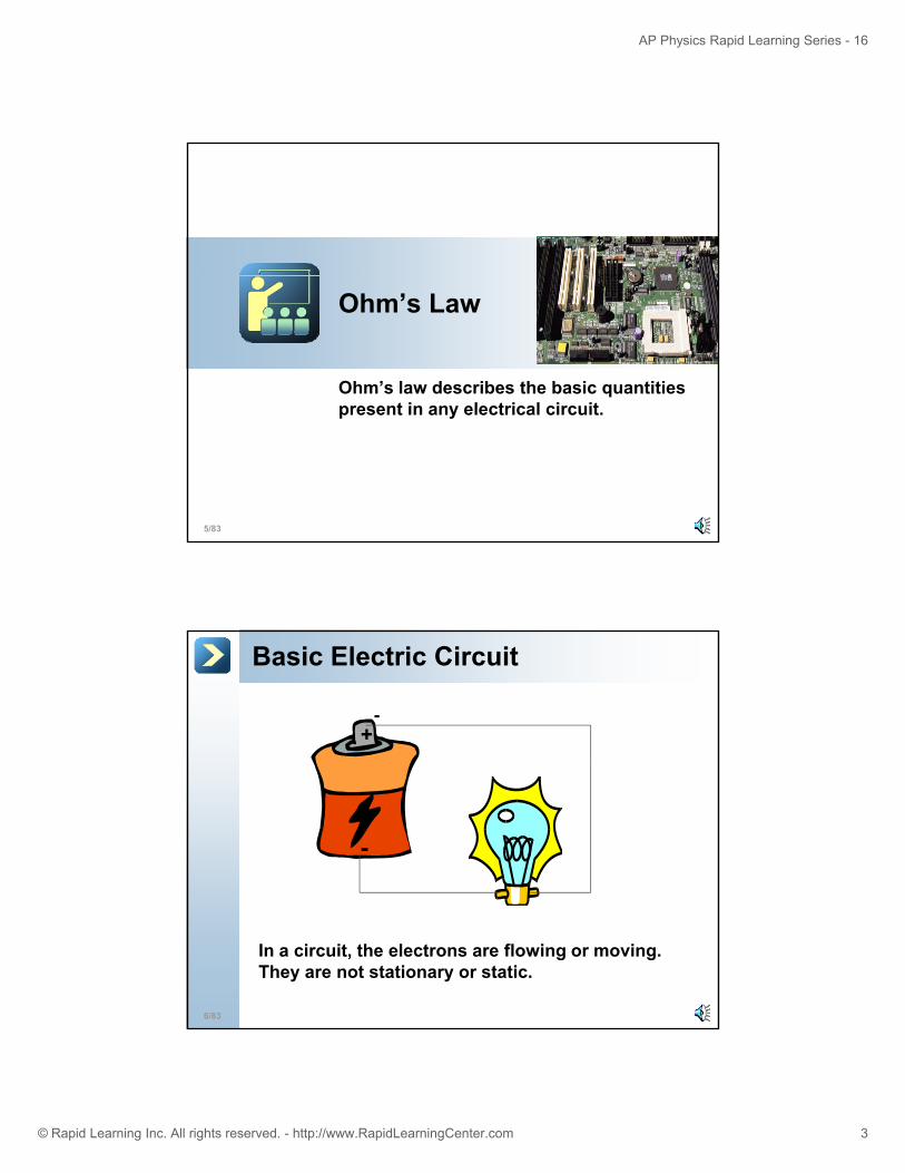
Ohm’s Law
Ohm’s law describes the basic quantities present in any electrical circuit
5/83
present in any electrical circuit.
Basic Electric Circuit
+-
-
6/83
In a circuit, the electrons are flowing or moving. They are not stationary or static.
Page 4
AP Physics Rapid Learning Series - 16
© Rapid Learning Inc. All rights reserved. - http://www.RapidLearningCenter.com 4
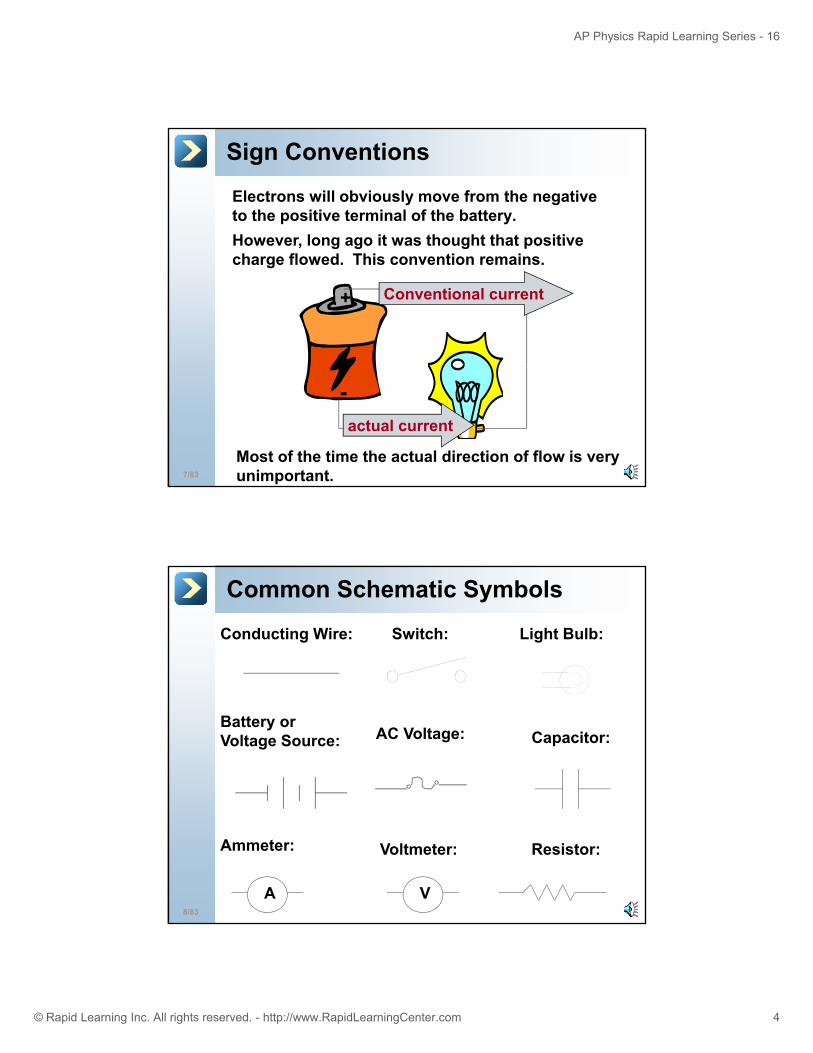
Sign Conventions
Electrons will obviously move from the negative to the positive terminal of the battery.However, long ago it was thought that positive
+ Conventional current
, g g g pcharge flowed. This convention remains.
7/83
Most of the time the actual direction of flow is very unimportant.
-actual current
Common Schematic Symbols
Conducting Wire: Switch: Light Bulb:
Battery or Voltage Source: AC Voltage: Capacitor:
8/83
A
Ammeter:
V
Voltmeter: Resistor:
Page 5
AP Physics Rapid Learning Series - 16
© Rapid Learning Inc. All rights reserved. - http://www.RapidLearningCenter.com 5
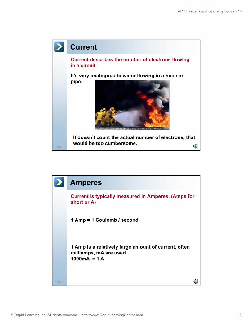
CurrentCurrent describes the number of electrons flowing in a circuit.
It’s very analogous to water flowing in a hose orIt s very analogous to water flowing in a hose or pipe.
9/83
It doesn’t count the actual number of electrons, that would be too cumbersome.
Amperes
Current is typically measured in Amperes. (Amps for short or A)
1 Amp = 1 Coulomb / second.
1 Amp is a relatively large amount of current, often
10/83
p y g ,milliamps, mA are used. 1000mA = 1 A
Page 6
AP Physics Rapid Learning Series - 16
© Rapid Learning Inc. All rights reserved. - http://www.RapidLearningCenter.com 6
Direct Current
DC, Direct Current: the charge flows in one direction only.
Examples: batteries
Conducting wire-
11/83
Alternating Current
AC, Alternating Current: electrons in the circuit move in one direction, then switch and then flow in the opposite direction.
Conducting wire
-- -- -
12/83
Examples: wall outlets
Page 7
AP Physics Rapid Learning Series - 16
© Rapid Learning Inc. All rights reserved. - http://www.RapidLearningCenter.com 7
AC Frequency
Since AC current changes direction, or oscillates, you can describe how often it changes direction.
Almost all US outlets use a frequency of 60 Hz.
13/83
Adapters/TransformersOften it is useful to convert AC into DC, or vice versa.
To save batteries, you’ve probably plugged a radio or CD player into the AC wall outlet with the help of an AC to
14/83
pDC adapter.
Page 8
AP Physics Rapid Learning Series - 16
© Rapid Learning Inc. All rights reserved. - http://www.RapidLearningCenter.com 8
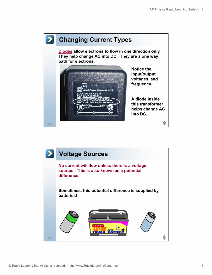
Changing Current Types
Diodes allow electrons to flow in one direction only. They help change AC into DC. They are a one way path for electrons.
Notice the input/output voltages, and frequency.
15/83
A diode inside this transformer helps change AC into DC.
Voltage Sources
No current will flow unless there is a voltage source. This is also known as a potential difference.
Sometimes, this potential difference is supplied by batteries!
16/83
Page 9
AP Physics Rapid Learning Series - 16
© Rapid Learning Inc. All rights reserved. - http://www.RapidLearningCenter.com 9
Electric Potential Analogy
Imagine a rock laying on level ground. It will not move anywhere (no current) since there is no difference in elevation (voltage).
17/83
Electron FlowHowever, an object at the top of a hill could roll down (current flowing) because of the elevation difference (voltage).
18/83
Page 10
AP Physics Rapid Learning Series - 16
© Rapid Learning Inc. All rights reserved. - http://www.RapidLearningCenter.com 10
Shocking Experience
To receive a shock, there must be a voltage difference applied to you. (electrons must “roll” downhill)
This is often referred to as an electric potential difference.
19/83
A Bird on a WireA bird could sit on a high voltage wire and receive no shock at all. Its entire body is at the same high voltage. No voltage difference.
20/83
However, if it touches the ground, tower, or wire with a different voltage then there would be a large voltage difference, and the current would flow!!!
Page 11
AP Physics Rapid Learning Series - 16
© Rapid Learning Inc. All rights reserved. - http://www.RapidLearningCenter.com 11
Grounding
To prevent electric shock, most cords have a third prong that is used to ground the cord.
21/83
If there are any extra electrons, they are immediately sent to the ground, not you.
Electrical Resistance
In almost all circuits, the electrons flow with some opposition or resistance.
Resistance is measured in units called Ohms.
The symbol is the Greek letter omega: Ω
22/83
Resistors on a circuit board
Page 12
AP Physics Rapid Learning Series - 16
© Rapid Learning Inc. All rights reserved. - http://www.RapidLearningCenter.com 12
Analogy
A hose is like wire
A pump is like voltage
23/83
As mentioned earlier, there are many similarities between electrical circuits, and “water” circuits.
A valve is like a switch
Ohm’s Law
Mr. Ohm discovered an extremely useful relationship: Voltage = Current x Resistance
IRV =Voltage, V
Resistance, Ω
24/83
Current, Amperes, A
Page 13
AP Physics Rapid Learning Series - 16
© Rapid Learning Inc. All rights reserved. - http://www.RapidLearningCenter.com 13
Ohm’s Law ExampleA light bulb operates on a 110 volt circuit. The bulb draws a current of .91 amps. What is the resistance of the light bulb?
V = IRR = V/IR = 110V/.91AI = 120.8 Ohms, Ω
25/83
Internal Resistance
You may measure the potential difference of a battery at 9V:
9V
26/83
9 V
Page 14
AP Physics Rapid Learning Series - 16
© Rapid Learning Inc. All rights reserved. - http://www.RapidLearningCenter.com 14
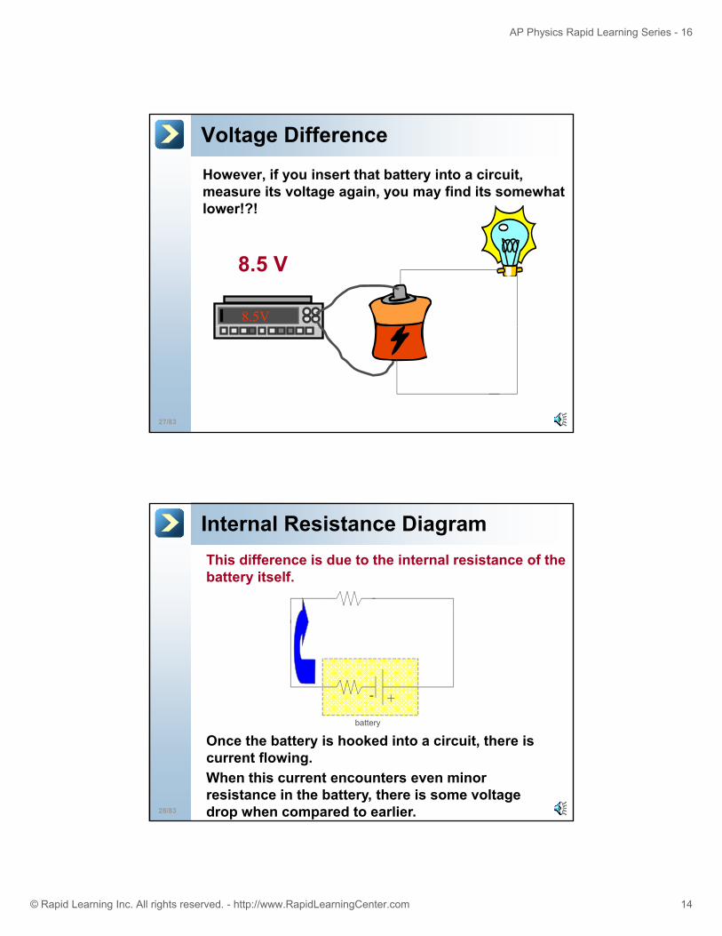
Voltage Difference
However, if you insert that battery into a circuit, measure its voltage again, you may find its somewhat lower!?!
8.5V
8.5 V
27/83
Internal Resistance DiagramThis difference is due to the internal resistance of the battery itself.
+-
28/83
Once the battery is hooked into a circuit, there is current flowing.
battery
When this current encounters even minor resistance in the battery, there is some voltage drop when compared to earlier.
Page 15
AP Physics Rapid Learning Series - 16
© Rapid Learning Inc. All rights reserved. - http://www.RapidLearningCenter.com 15
EMF
When in a circuit, the reduced voltage is referred to as the terminal voltage.
29/83
The potential difference when nothing is connected is referred to as the EMF, electromotive force. This term has nothing to do with the traditional notion of force.
Lost Voltage
When you take away the voltage lost due to the internal resistance from the EMF, the remaining voltage is the terminal voltage:
EMF - IRbattery = Vterminal
voltage is the terminal voltage:
30/83
EMF - “lost voltage” = terminal voltage
Page 16
AP Physics Rapid Learning Series - 16
© Rapid Learning Inc. All rights reserved. - http://www.RapidLearningCenter.com 16
Energy Conservation
Energy, or voltage, is still conserved. Some is simply used up by the internal resistance of the battery itself.
31/83
The actual internal resistance of most batteries is very small, less than 1 Ohm.
Internal Resistance Example
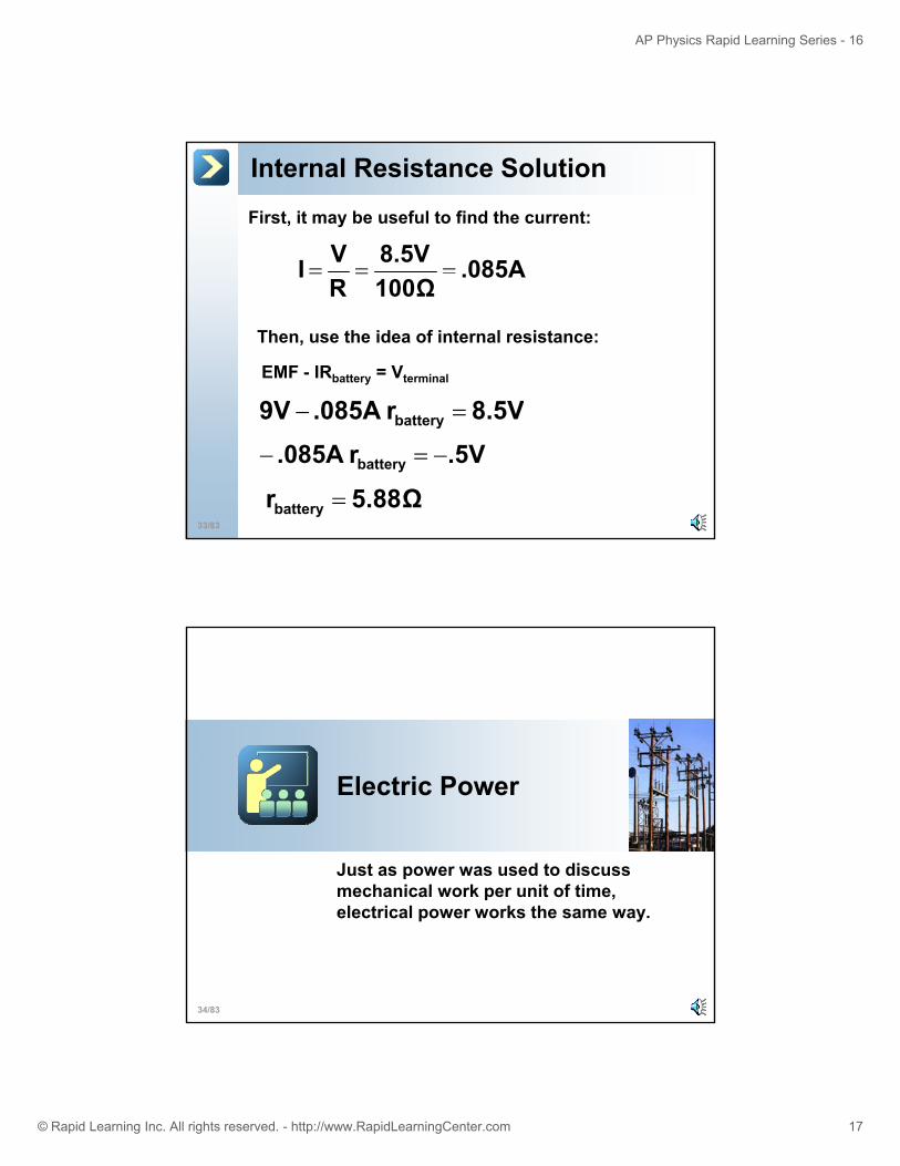
As in the previous discussion, the 9 V battery has a terminal voltage of 8.5 V when connected to a 100 Ω resistor. What is the internal resistance of the battery?
32/83
?
Page 17
AP Physics Rapid Learning Series - 16
© Rapid Learning Inc. All rights reserved. - http://www.RapidLearningCenter.com 17
Internal Resistance Solution
First, it may be useful to find the current:
.085A8.5VVI ===
Then, use the idea of internal resistance:
EMF - IRbattery = Vterminal
.085A100ΩR
I
8 5Vr085A9V
33/83
8.5Vr.085A 9V battery =−
5.88Ωr battery =
.5Vr.085A battery −=−
Electric Power
Just as power was used to discuss mechanical work per unit of time
34/83
mechanical work per unit of time, electrical power works the same way.
Page 18
AP Physics Rapid Learning Series - 16
© Rapid Learning Inc. All rights reserved. - http://www.RapidLearningCenter.com 18
Electric Power
Just like mechanical power, electrical power describes work done per unit of time.
1 Watt = 1 Joule / 1 second
1000 Watts = 1 kilowatt
35/83
Power Formula
In terms of electrical quantities, power can be calculated by multiplying current x voltage.
IVP =
Electric Potential, V
Electric Power
Watts, W.
36/83
Current, Amperes, A
Page 19
AP Physics Rapid Learning Series - 16
© Rapid Learning Inc. All rights reserved. - http://www.RapidLearningCenter.com 19
Alternate Power Formula
Another formula for power can be found.
Since V = IR
And P = IV
Substitute V into the power equation and obtain:
37/83
P = I2R
Power ProblemHow much current flows through a 100W light bulb if its connected to a 120V fixture?
38/83
Page 20
AP Physics Rapid Learning Series - 16
© Rapid Learning Inc. All rights reserved. - http://www.RapidLearningCenter.com 20
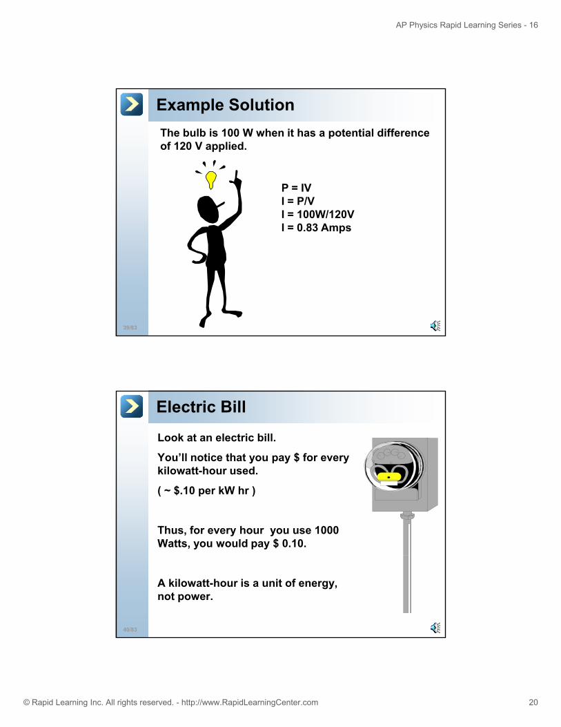
Example SolutionThe bulb is 100 W when it has a potential difference of 120 V applied.
P = IVI = P/VI = 100W/120VI = 0.83 Amps
39/83
Electric Bill
Look at an electric bill.
You’ll notice that you pay $ for every kilowatt-hour used.kilowatt hour used.
( ~ $.10 per kW hr )
Thus, for every hour you use 1000 Watts, you would pay $ 0.10.
40/83
A kilowatt-hour is a unit of energy, not power.
Page 21
AP Physics Rapid Learning Series - 16
© Rapid Learning Inc. All rights reserved. - http://www.RapidLearningCenter.com 21
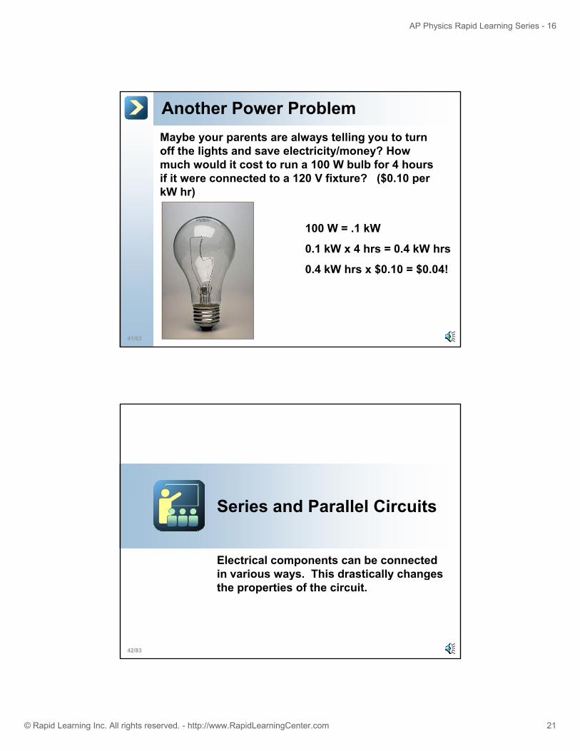
Another Power ProblemMaybe your parents are always telling you to turn off the lights and save electricity/money? How much would it cost to run a 100 W bulb for 4 hours if it were connected to a 120 V fixture? ($0 10 perif it were connected to a 120 V fixture? ($0.10 per kW hr)
100 W = .1 kW
0.1 kW x 4 hrs = 0.4 kW hrs
41/83
0.4 kW hrs x $0.10 = $0.04!
Series and Parallel Circuits
Electrical components can be connected in various ways This drastically changes
42/83
in various ways. This drastically changes the properties of the circuit.
Page 22
AP Physics Rapid Learning Series - 16
© Rapid Learning Inc. All rights reserved. - http://www.RapidLearningCenter.com 22
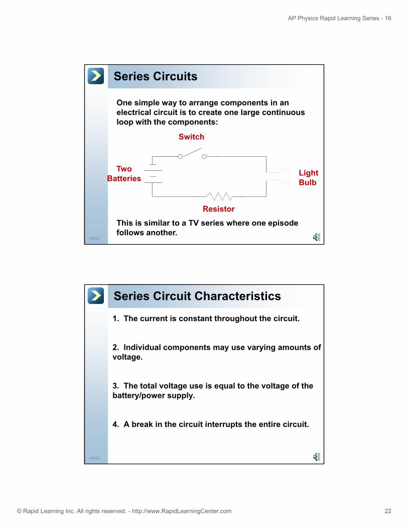
Series Circuits
One simple way to arrange components in an electrical circuit is to create one large continuous loop with the components:loop with the components:
Two Batteries
Switch
Light Bulb
43/83
Bulb
Resistor
This is similar to a TV series where one episode follows another.
Series Circuit Characteristics
1. The current is constant throughout the circuit.
f2. Individual components may use varying amounts of voltage.
3. The total voltage use is equal to the voltage of the battery/power supply.
44/83
4. A break in the circuit interrupts the entire circuit.
Page 23
AP Physics Rapid Learning Series - 16
© Rapid Learning Inc. All rights reserved. - http://www.RapidLearningCenter.com 23
Adding Resistors in Series
When resistors are added in series, the total resistance of the circuit is the sum of those individual resistors.
...RRRR 321S ++=
45/83
Series or total
combined resistance, Ω
Individual resistors, Ω
Parallel Circuits
Another way to connect a circuit is in parallel. In this arrangement, each component is connected separately in its own “loop”.
Two Batteries
46/83
Three Resistors in Parallel
Page 24
AP Physics Rapid Learning Series - 16
© Rapid Learning Inc. All rights reserved. - http://www.RapidLearningCenter.com 24
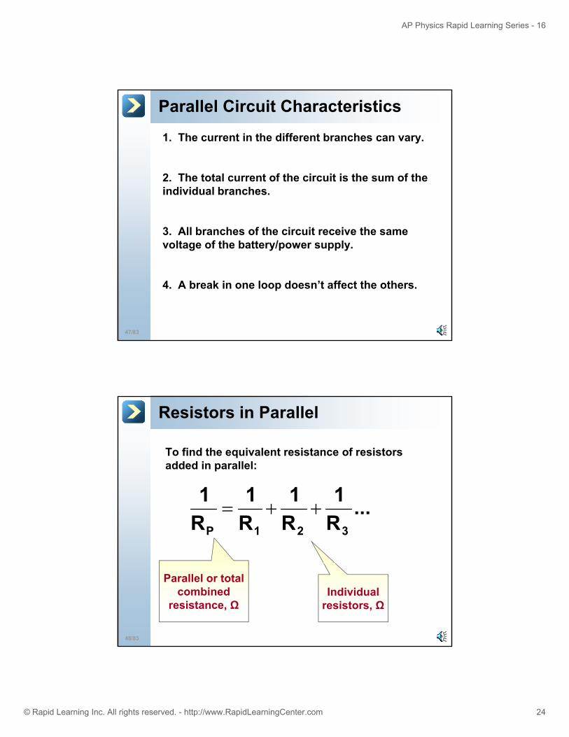
Parallel Circuit Characteristics
1. The current in the different branches can vary.
f f2. The total current of the circuit is the sum of the individual branches.
3. All branches of the circuit receive the same voltage of the battery/power supply.
47/83
4. A break in one loop doesn’t affect the others.
Resistors in Parallel
To find the equivalent resistance of resistors added in parallel:
...R1
R1
R1
R1
321P
++=
48/83
Parallel or total combined
resistance, ΩIndividual
resistors, Ω
Page 25
AP Physics Rapid Learning Series - 16
© Rapid Learning Inc. All rights reserved. - http://www.RapidLearningCenter.com 25
Parallel Resistor ExampleCalculate the total effective resistance of two 10 Ohm resistors connected in parallel.
111+
21P RRR+=
10Ω1
10Ω1
R1
P
+=
21
Combine, use common
denominator if needed
49/83
10Ω2
R1
P
=
5ΩRP =
Take the reciprocal of each side of
equation
Parallel Resistor Observations
5 Ohms. Notice that the total overall resistance is lower than either one of them individually!
This occurs because there are multiple paths for the electrons to take, lowering their resistance.
50/83
Page 26
AP Physics Rapid Learning Series - 16
© Rapid Learning Inc. All rights reserved. - http://www.RapidLearningCenter.com 26
Too Many Resistors
Adding more and more devices in paralleldevices in parallel decreases the total or overall resistance. This allows too much current to flow! Obviously this can be dangerous!
51/83
Combination Question
Often, when one Christmas tree light goes out, they all go out!!! How are these type of lights wired together?
52/83
These are wired in series. A parallel arrangement would eliminate this…
Page 27
AP Physics Rapid Learning Series - 16
© Rapid Learning Inc. All rights reserved. - http://www.RapidLearningCenter.com 27
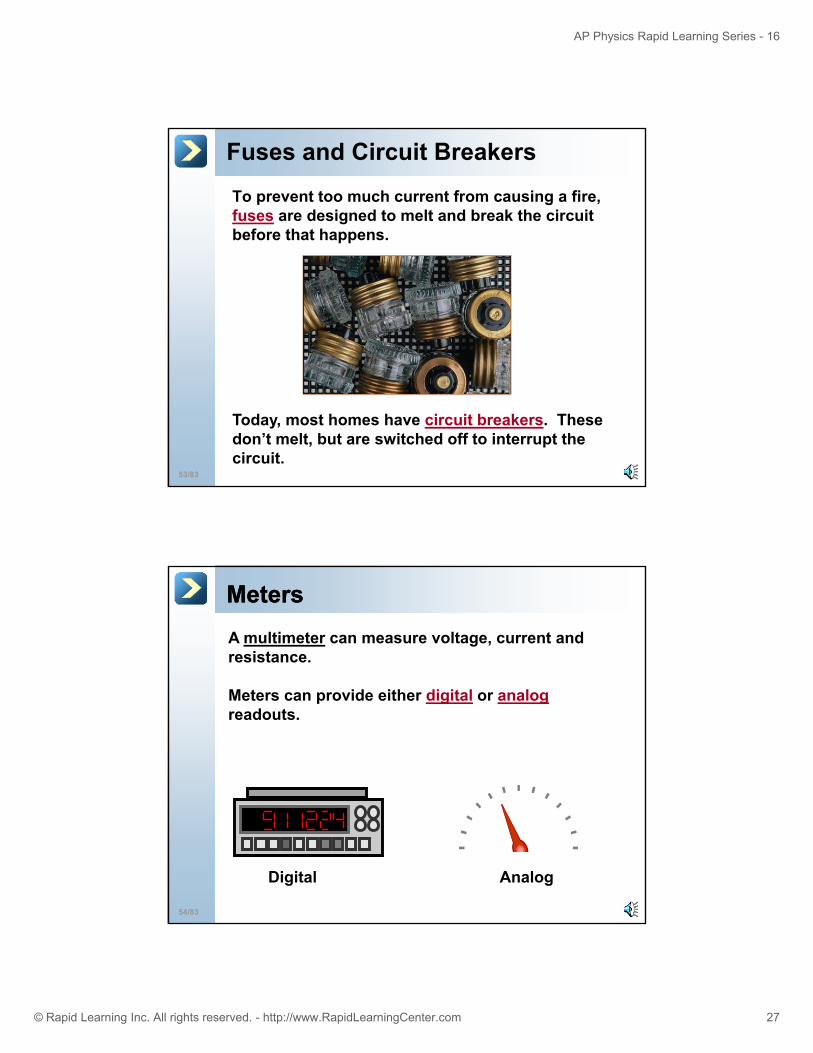
Fuses and Circuit Breakers
To prevent too much current from causing a fire, fuses are designed to melt and break the circuit before that happens.
53/83
Today, most homes have circuit breakers. These don’t melt, but are switched off to interrupt the circuit.
MetersMetersA multimeter can measure voltage, current and resistance.
Meters can provide either digital or analogreadouts.
54/83
Digital Analog
Page 28
AP Physics Rapid Learning Series - 16
© Rapid Learning Inc. All rights reserved. - http://www.RapidLearningCenter.com 28
Measuring Current
Current can be measured using an ammeter or a multimeter.
A meter that only measures current iscalled an ammeter.
55/83
Using Meters to Measure Current:
When measuring current, the meter leads are connected in-line with the load or voltage source.
A
56/83
Page 29
AP Physics Rapid Learning Series - 16
© Rapid Learning Inc. All rights reserved. - http://www.RapidLearningCenter.com 29
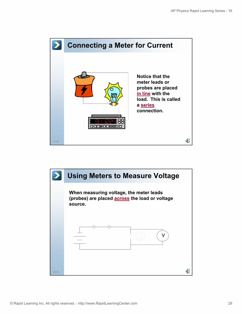
Connecting a Meter for Current
Notice that the meter leads or probes are placed in line with the load. This is called a series
ti
57/83
connection.
Using Meters to Measure Voltage
When measuring voltage, the meter leads (probes) are placed across the load or voltage source
V
source.
58/83
Page 30
AP Physics Rapid Learning Series - 16
© Rapid Learning Inc. All rights reserved. - http://www.RapidLearningCenter.com 30
Connecting a Meter for Voltage
Notice that the meter leads or probes are placed across the load. This is called a parallel connection.
59/83
Circuit Problems
This section will detail how to calculate the various electrical quantities in a
60/83
the various electrical quantities in a circuit.
Page 31
AP Physics Rapid Learning Series - 16
© Rapid Learning Inc. All rights reserved. - http://www.RapidLearningCenter.com 31
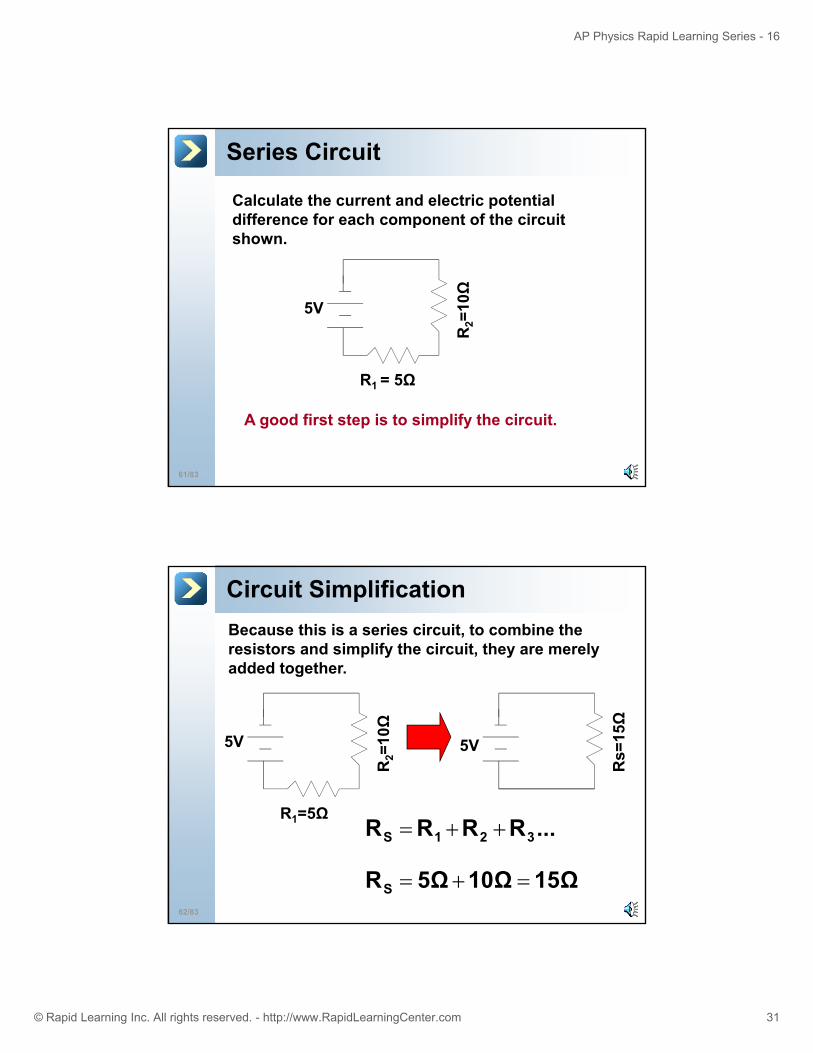
Series Circuit
Calculate the current and electric potential difference for each component of the circuit shown.
R2=
10Ω
5V
61/83
R1 = 5Ω
A good first step is to simplify the circuit.
Circuit SimplificationBecause this is a series circuit, to combine the resistors and simplify the circuit, they are merely added together.
R2=
10Ω
5V 5V
Rs=
15Ω
62/83
R1=5Ω...RRRR 321S ++=
15Ω10Ω5ΩRS =+=
Page 32
AP Physics Rapid Learning Series - 16
© Rapid Learning Inc. All rights reserved. - http://www.RapidLearningCenter.com 32
Current in a Series Circuit
5V =15Ω
IRV =VI =5V
Rs=
Use the voltage of the power supply and the total resistance of the circuit to find the total current
R.33A
15Ω5VI ==
63/83
flowing through the circuit.
Because the electron flow has no where else to go, this amount is also the current flowing through both resistors. I1 and I2 is that same .33 Amperes.
Voltage in a Series Circuit
10Ω
5V
Since we know the current flowing through each resistor, we can use Ohm’s
R2=
R1=5Ω
5Vlaw to find the potential difference for each of those resistors.
IRV1= IRV2=
64/83
) (.33A)(5ΩV1=
1.67VV1 =Notice how the sum of the two voltages adds up to the power supply for the circuit.
) (.33A)(10ΩV2=3.33VV2 =
Page 33
AP Physics Rapid Learning Series - 16
© Rapid Learning Inc. All rights reserved. - http://www.RapidLearningCenter.com 33
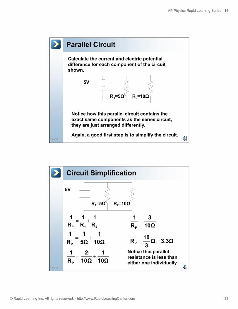
Parallel Circuit
Calculate the current and electric potential difference for each component of the circuit shown.
5V
R1=5Ω R2=10Ω
65/83
Notice how this parallel circuit contains the exact same components as the series circuit, they are just arranged differently.
Again, a good first step is to simplify the circuit.
Circuit Simplification
5V
21P R1
R1
R1
+=
R1=5Ω R2=10Ω
11110Ω
3R1
P
=
10
66/83
10Ω5ΩRP
+=
10Ω1
10Ω2
R1
P
+=
3.3ΩΩ3
10RP ==
Notice this parallel resistance is less than either one individually.
Page 34
AP Physics Rapid Learning Series - 16
© Rapid Learning Inc. All rights reserved. - http://www.RapidLearningCenter.com 34
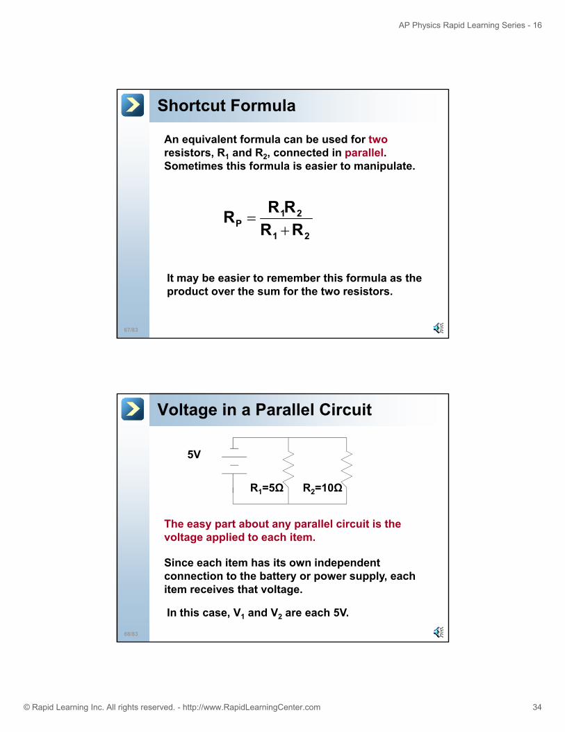
Shortcut Formula
An equivalent formula can be used for tworesistors, R1 and R2, connected in parallel. Sometimes this formula is easier to manipulate.
21
21P RR
RRR+
=
67/83
It may be easier to remember this formula as the product over the sum for the two resistors.
Voltage in a Parallel Circuit
5V
R1=5Ω R2=10Ω
The easy part about any parallel circuit is the voltage applied to each item.
Si h it h it i d d t
68/83
Since each item has its own independent connection to the battery or power supply, each item receives that voltage.
In this case, V1 and V2 are each 5V.
Page 35
AP Physics Rapid Learning Series - 16
© Rapid Learning Inc. All rights reserved. - http://www.RapidLearningCenter.com 35
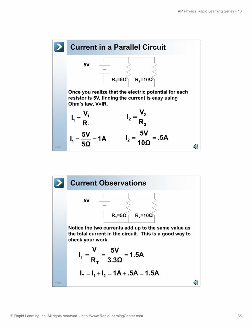
Current in a Parallel Circuit
5V
R1=5Ω R2=10Ω
Once you realize that the electric potential for each resistor is 5V, finding the current is easy using Ohm’s law, V=IR.
V 2VI
69/83
1
11 R
VI =2
22 R
VI =
1A5Ω5VI1 == .5A
10Ω5VI2 ==
Current Observations
5V
R1=5Ω R2=10Ω
Notice the two currents add up to the same value as the total current in the circuit. This is a good way to check your work.
5VV
70/83
1.5A3.3Ω5V
RV
IT
T ===
1.5A.5A1AIII 21T =+=+=
Page 36
AP Physics Rapid Learning Series - 16
© Rapid Learning Inc. All rights reserved. - http://www.RapidLearningCenter.com 36
Kirchhoff’s Laws
Kirchhoff’s laws describe more complex circuits The concept is relatively simple
71/83
circuits. The concept is relatively simple, but the application to a circuit can be a bit complex.
Multiple Voltage Sources
Typically, Kirchhoff’s laws are used when there are multiple voltage sources and/or loops in the circuit.
+ _
72/83
The multiple voltage sources may even “oppose” each other.
Page 37
AP Physics Rapid Learning Series - 16
© Rapid Learning Inc. All rights reserved. - http://www.RapidLearningCenter.com 37
Junction Rule
The current going into a junction (intersection) is equal to the current leaving the junction.
8 A
4 A4 A
73/83
This junction rule can be considered a restatement of conservation of charge.
4 A4 A Conducting wire
Loop RuleThe sum of the voltage changes for all elements in a loop must equal zero.
VR
esis
tor
1V
4V
74/83
The loop rule can be considered a restatement of conservation of energy.
03V1V4V =−−+Resistor 3V
Page 38
AP Physics Rapid Learning Series - 16
© Rapid Learning Inc. All rights reserved. - http://www.RapidLearningCenter.com 38
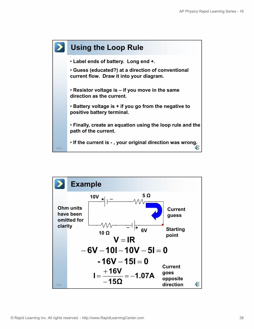
Using the Loop Rule
• Guess (educated?) at a direction of conventional current flow. Draw it into your diagram.
• Label ends of battery. Long end +.
current flow. Draw it into your diagram.
• Resistor voltage is – if you move in the same direction as the current.
• Battery voltage is + if you go from the negative to positive battery terminal.
75/83
• Finally, create an equation using the loop rule and the path of the current.
• If the current is - , your original direction was wrong.
p y
Example
+ _10V 5 Ω
Current Ohm units have been
+_
6V10 Ω
guess
05I10V10I6V =−−−−IRV =
have been omitted for clarity Starting
point
76/83
05I10V10I6V =015I16V- =−
1.07A15Ω16VI −=
−+
=Current goes opposite direction
Page 39
AP Physics Rapid Learning Series - 16
© Rapid Learning Inc. All rights reserved. - http://www.RapidLearningCenter.com 39
Multiple Loops
When there are multiple loops, both the loop and junction rule may be required.
You may have multiple unknowns.
You must have as many equations as unknowns in order to solve.
77/83
Once one variable is found, substitute it to find the others.
Kirchhoff’s Laws ExampleI1
I2
312 III +=22 Ω+ _
9V
I2
I3 6V
15 Ω
78/83
09V22I-15I 12 =+−Top loop:
Bottom loop: 015I6V 2 =−−
6V
Page 40
AP Physics Rapid Learning Series - 16
© Rapid Learning Inc. All rights reserved. - http://www.RapidLearningCenter.com 40
Problem Solving - 2Work with the bottom loop first since its simplest:
Amps156I2 −=015I6V 2 =−− 15
Thus, our original guess for the direction of I2 was wrong!
Put I2 back in and find I1.
09V22I-15I 12 =+−
79/83
12
09V22I- 15(-.4) 1 =+−
0922I6 1 =+− .68AI1 =
Problem Solving - 3With our revised current direction, we now know I1 and I2.
22 Ω+ _I1
6V
15 Ω
I2
I3
80/83
.4A +.68A = 1.08A in the opposite direction to what we originally thought.
I3
We can finally get I3:
Page 41
AP Physics Rapid Learning Series - 16
© Rapid Learning Inc. All rights reserved. - http://www.RapidLearningCenter.com 41
Parallel connections have
Parallel connections have
Current is charge per unit of time
Current is charge per unit of time
Kirchhoff’s loop and junction rule Kirchhoff’s loop and junction rule
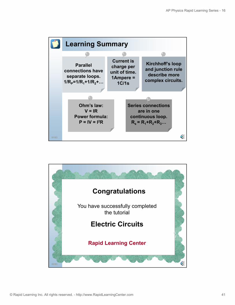
Learning Summary
Series connectionsSeries connections
connections have separate loops.
1/RP=1/R1+1/R2+…
connections have separate loops.
1/RP=1/R1+1/R2+…
unit of time. 1Ampere =
1C/1s
unit of time. 1Ampere =
1C/1s
jdescribe more
complex circuits.
jdescribe more
complex circuits.
Ohm’s law:Ohm’s law:
81/83
Series connections are in one
continuous loop.Rs = R1+R2+R3…
Series connections are in one
continuous loop.Rs = R1+R2+R3…
Ohm s law:V = IR
Power formula:P = IV = I2R
Ohm s law:V = IR
Power formula:P = IV = I2R
Congratulations
You have successfully completed the tutorial
Electric Circuits
82/83
Rapid Learning Center
Page 42
AP Physics Rapid Learning Series - 16
© Rapid Learning Inc. All rights reserved. - http://www.RapidLearningCenter.com 42
Rapid Learning Center
Wh t’ N t
Chemistry :: Biology :: Physics :: Math
What’s Next …
Step 1: Concepts – Core Tutorial (Just Completed)
Step 2: Practice – Interactive Problem Drill
Step 3: Recap Super Review Cheat Sheet
83/83
Step 3: Recap – Super Review Cheat Sheet
Go for it!
http://www.RapidLearningCenter.com