38
ELECTRIC CIRCUITS ECSE-2010 Spring 2003 Class 3
| Date post: | 01-Jan-2016 |
| Category: |
Documents |
| Upload: | blaise-hancock |
| View: | 214 times |
| Download: | 0 times |

ELECTRIC CIRCUITSECSE-2010
Spring 2003 Class 3
ASSIGNMENTS DUE
• Today (Thursday):• Will introduce PSpice• Activity 3-1 (In Class) using PSpice• Will do Experiment 1; Report Due Jan 27
• Next Monday:• No Classes – Martin Luther King Day
• Next Tuesday/Wednesday:• HW #1 Due• Activities 4-1, 4-2, 4-3 (In Class)• 4-2 in NOT in your Supplement
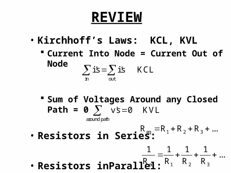
REVIEW
• Kirchhoff’s Laws: KCL, KVL Current Into Node = Current Out of Node
Sum of Voltages Around any Closed Path = 0
• Resistors in Series:
• Resistors inParallel:
in out
i's i's KCL
around path
v's 0 KVLeq 1 2 3R R R R ...
eq 1 2 3
1 1 1 1...
R R R R

KIRCHHOFF’S LAWS
1i 2i
3i
1 2 3KCL: i i i
1v
3v
2 v
1 2 3KVL: v v v

RESISTORS IN SERIES
1R2R eqR
eq 1 2R R R
v
v
i i
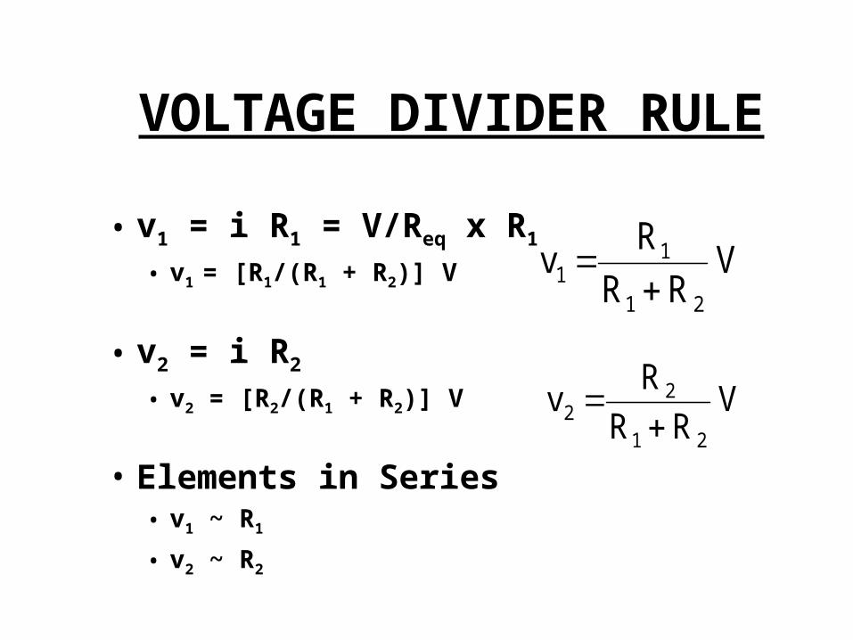
VOLTAGE DIVIDER RULE
• v1 = i R1 = V/Req x R1
• v1 = [R1/(R1 + R2)] V
• v2 = i R2
• v2 = [R2/(R1 + R2)] V
• Elements in Series• v1 ~ R1
• v2 ~ R2
V R R
R v
21
11
V R R
R v
21
22
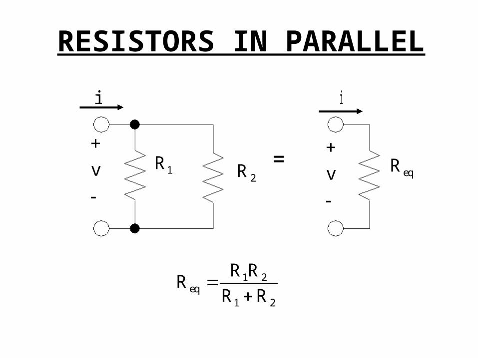
RESISTORS IN PARALLEL
1R2R eqR
1 2eq
1 2
R RR
R R
v
v
i i
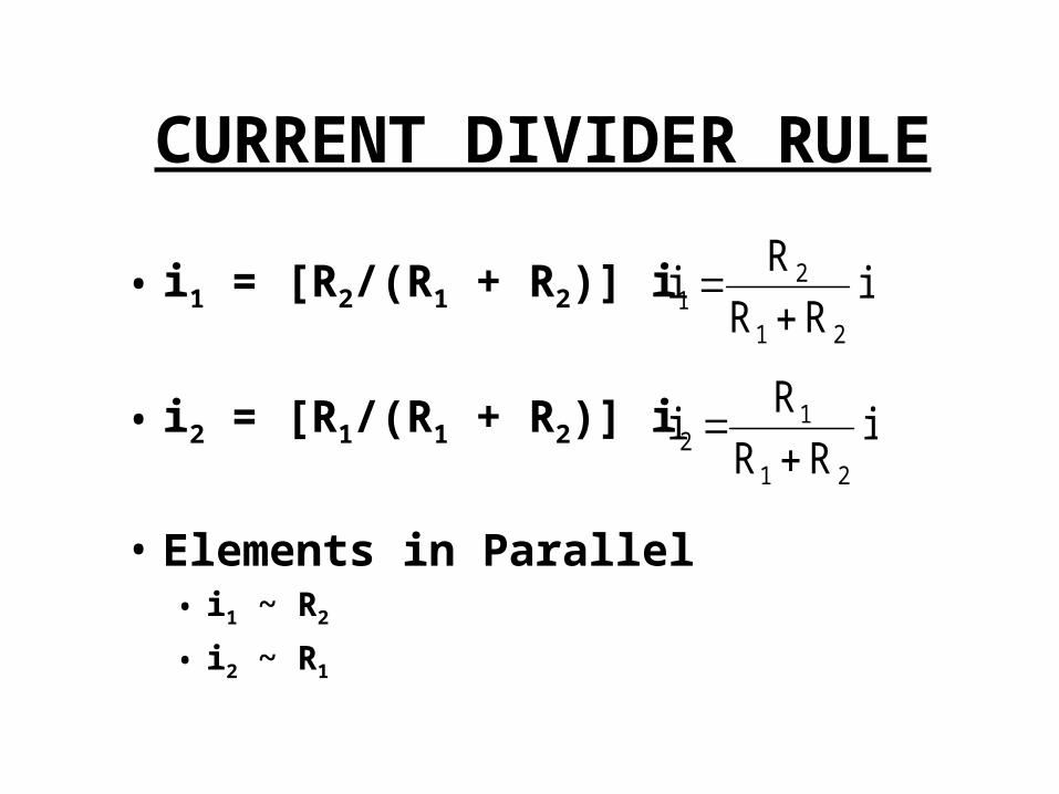
CURRENT DIVIDER RULE
• i1 = [R2/(R1 + R2)] i
• i2 = [R1/(R1 + R2)] i
• Elements in Parallel• i1 ~ R2
• i2 ~ R1
i R R
R i
21
21
i R R
R i
21
12

PSPICE
• Widely Used Simulation Package Industry Standard for Circuits and Electronics
• Student Version is FREE http://cadencepcb.com/products/downloads/PSpicestudent/
default/asp
We will use PSpice A/D and Schematics Could use Capture in place of Schematics
• Get a Copy and Use it Often
PSPICE
• PSpice has Many “Rules”: Will build up slowly
• Use PSpice for Circuits that are Computationally Challenging:
• Will Often Analyze a Circuit to Learn Principles - Then “test” with PSpice:
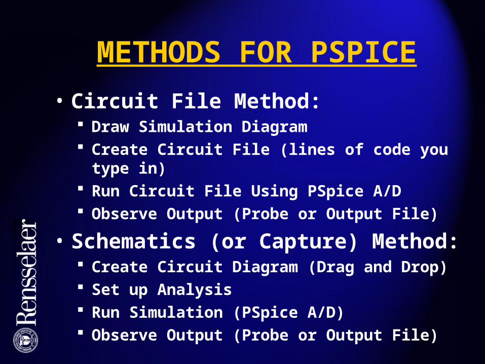
METHODS FOR PSPICE
• Circuit File Method: Draw Simulation Diagram Create Circuit File (lines of code you type in) Run Circuit File Using PSpice A/D Observe Output (Probe or Output File)
• Schematics (or Capture) Method: Create Circuit Diagram (Drag and Drop) Set up Analysis Run Simulation (PSpice A/D) Observe Output (Probe or Output File)

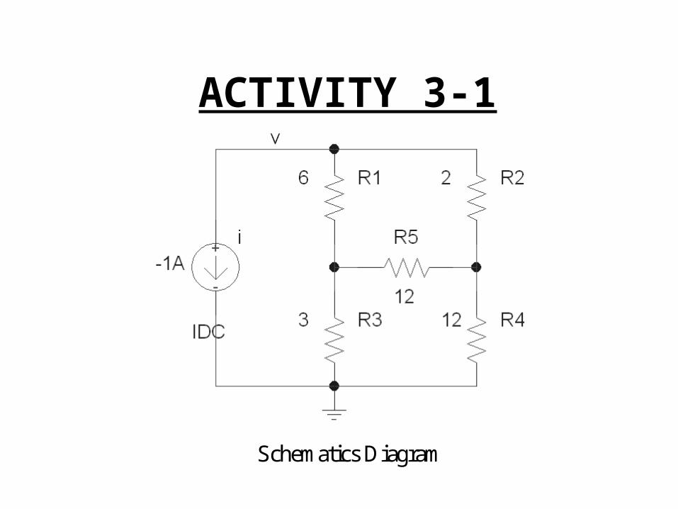
ACTIVITY 3-1
6 2
12
3 12
i
v
2v
23 v
eqPlot v vs. i Find R
Resistive Bridge Circuit
eqR
Nothing in Series or Parallel!
eq
vR
i
2 23Will also find v , v
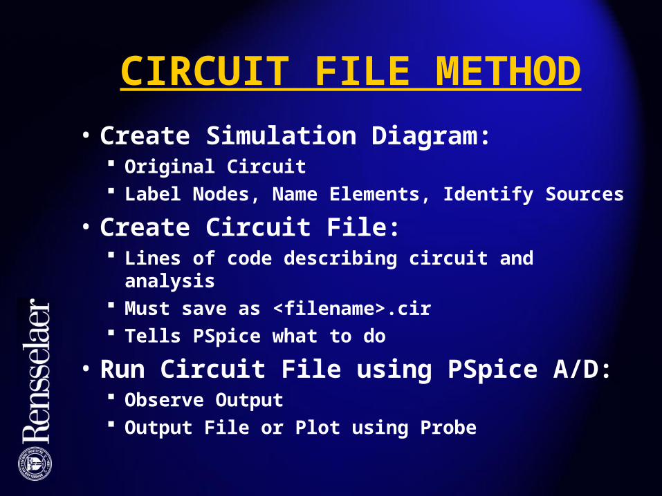
CIRCUIT FILE METHOD
• Create Simulation Diagram: Original Circuit Label Nodes, Name Elements, Identify Sources
• Create Circuit File: Lines of code describing circuit and analysis Must save as <filename>.cir Tells PSpice what to do
• Run Circuit File using PSpice A/D: Observe Output Output File or Plot using Probe
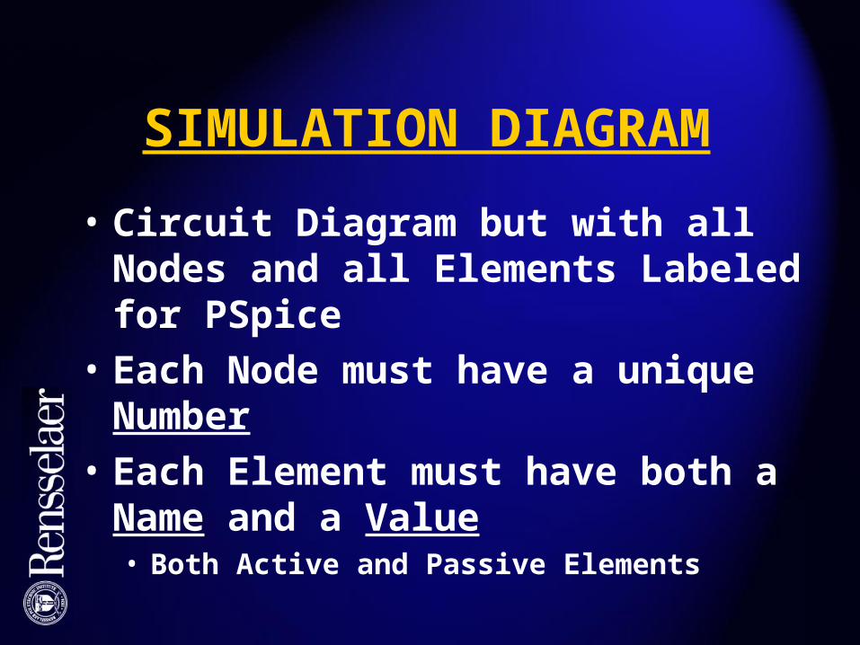
SIMULATION DIAGRAM
• Circuit Diagram but with all Nodes and all Elements Labeled for PSpice
• Each Node must have a unique Number
• Each Element must have both a Name and a Value• Both Active and Passive Elements
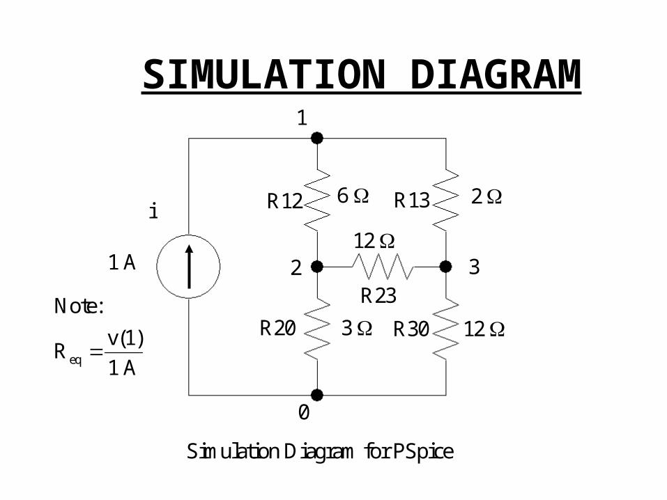
SIMULATION DIAGRAM
6 2
12
12 3
1 A
1
0
2 3
R12
R20
R13
R30
Simulation Diagram for PSpice
i
R23
eq
Note:
v(1)R
1 A

CIRCUIT FILES
• Circuit File Describes Circuit to PSpice and Tells PSpice What to Do:
• First Line Not Used by PSpice: => Name
• To Describe a Current Source:i 0 1 DC 1
Name of Source = i; “i” means current (i or I)
Current flows from Node 0 to Node 1
DC Source
1 Amp

CIRCUIT FILES
• To Describe a Voltage Sourcev4 1 0 DC 2
Name of Source = v4; “v” means voltage
Positive terminal is Node 1
Negative terminal is Node 0
DC Source
2 Volts
CIRCUIT FILES
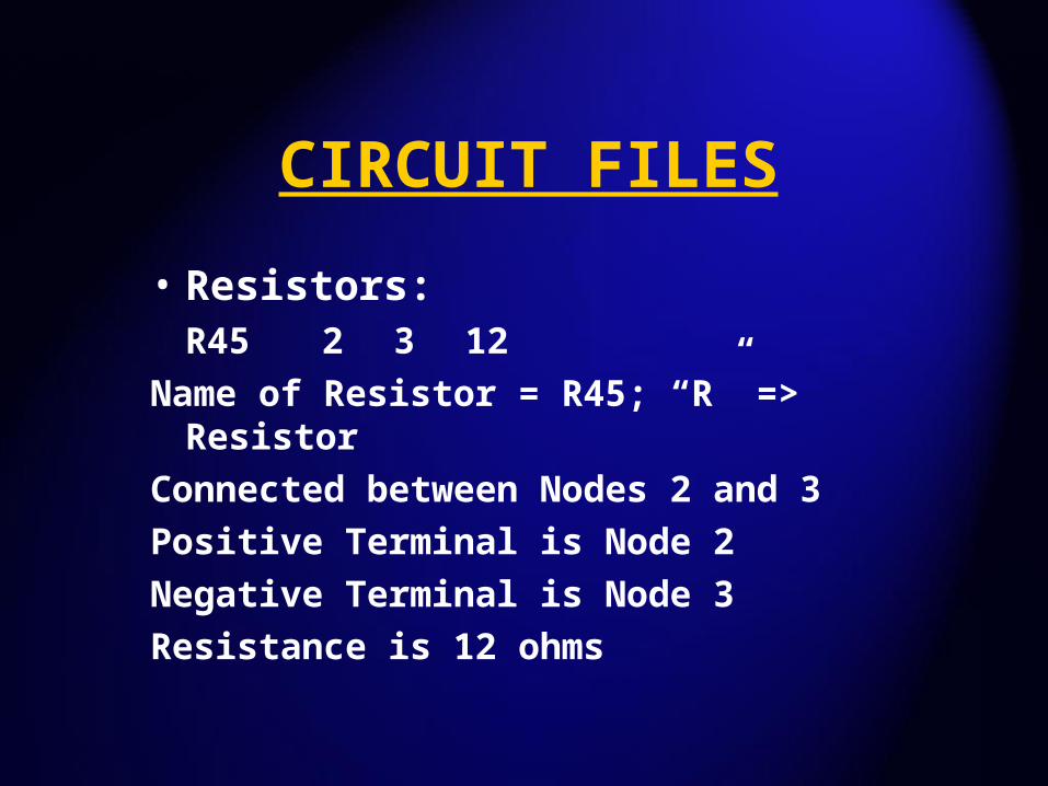
• Resistors:R45 2 3 12
Name of Resistor = R45; “R” => Resistor
Connected between Nodes 2 and 3
Positive Terminal is Node 2
Negative Terminal is Node 3
Resistance is 12 ohms
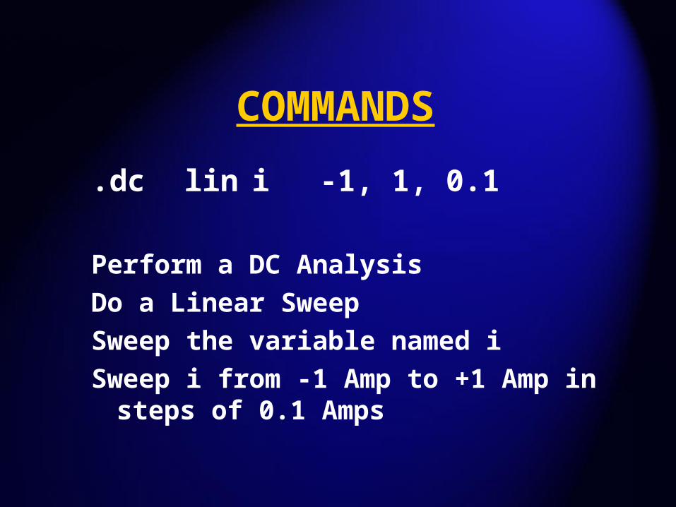
COMMANDS
.dc lin i -1, 1, 0.1
Perform a DC Analysis
Do a Linear Sweep
Sweep the variable named i
Sweep i from -1 Amp to +1 Amp in steps of 0.1 Amps
COMMANDS
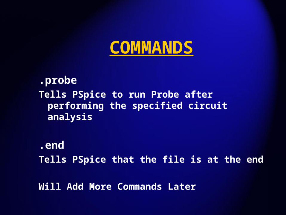
.probeTells PSpice to run Probe after performing
the specified circuit analysis
.endTells PSpice that the file is at the end
Will Add More Commands Later
PROCEDURE
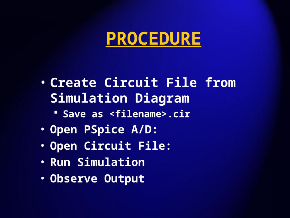
• Create Circuit File from Simulation Diagram Save as <filename>.cir
• Open PSpice A/D:• Open Circuit File:• Run Simulation• Observe Output

ACTIVITY 3-1
6 2
12
12 3
1
0
2 3
R12
R20
R13
R30
Simulation Diagram for PSpice
i 1 A
eq
Note:
v(1)R
1 A
v
iLabel Nodes
Name Elements

ACTIVITY 3-1
• Open PSpice A/D
• Under File: Select New - Text File
• Type in Circuit File
• Save as <filename>.cir
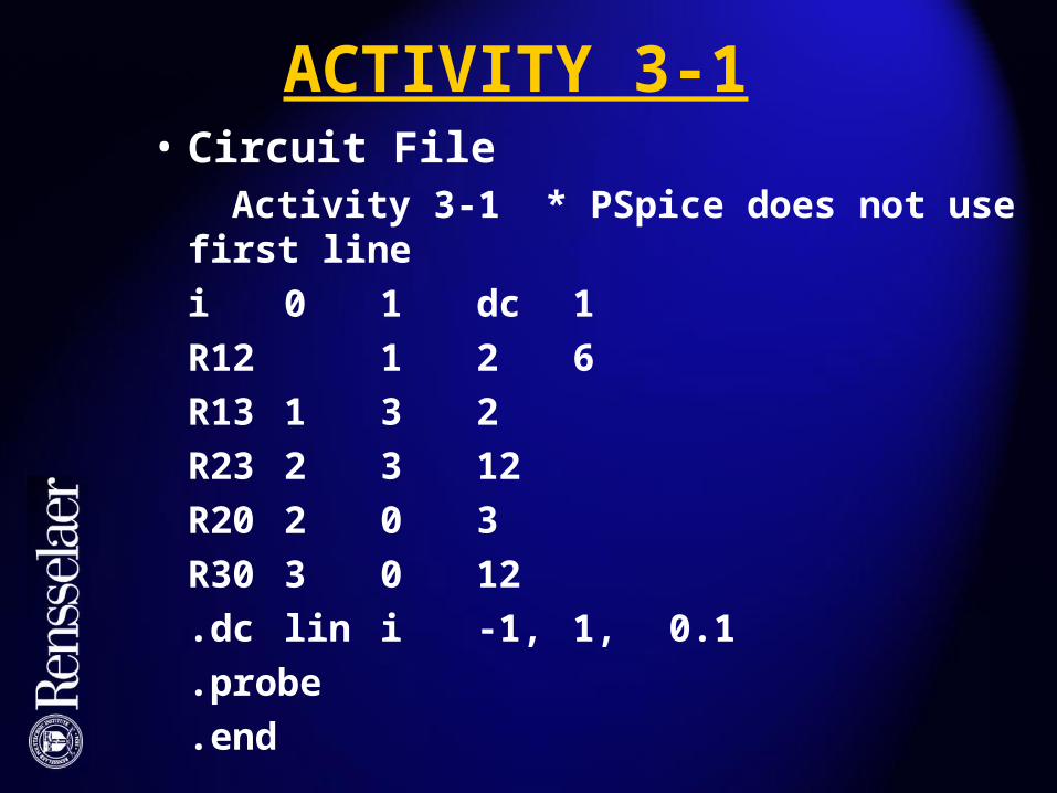
ACTIVITY 3-1• Circuit File Activity 3-1 * PSpice does not use first line
i 0 1 dc 1
R12 1 2 6
R13 1 3 2
R23 2 3 12
R20 2 0 3
R30 3 0 12
.dc lin i -1, 1, 0.1
.probe
.end

ACTIVITY 3-1• Under Simulation: Select Run <filename>
• If Errors: => Error Message => Correct
• If it Runs, Probe comes up automatically
• Horizontal axis = i (from -1 to + 1)
• Under Trace: Select v(1)• v(1) = Voltage at Node 1
• Note that Req = 5 ohms
SCHEMATICS METHOD
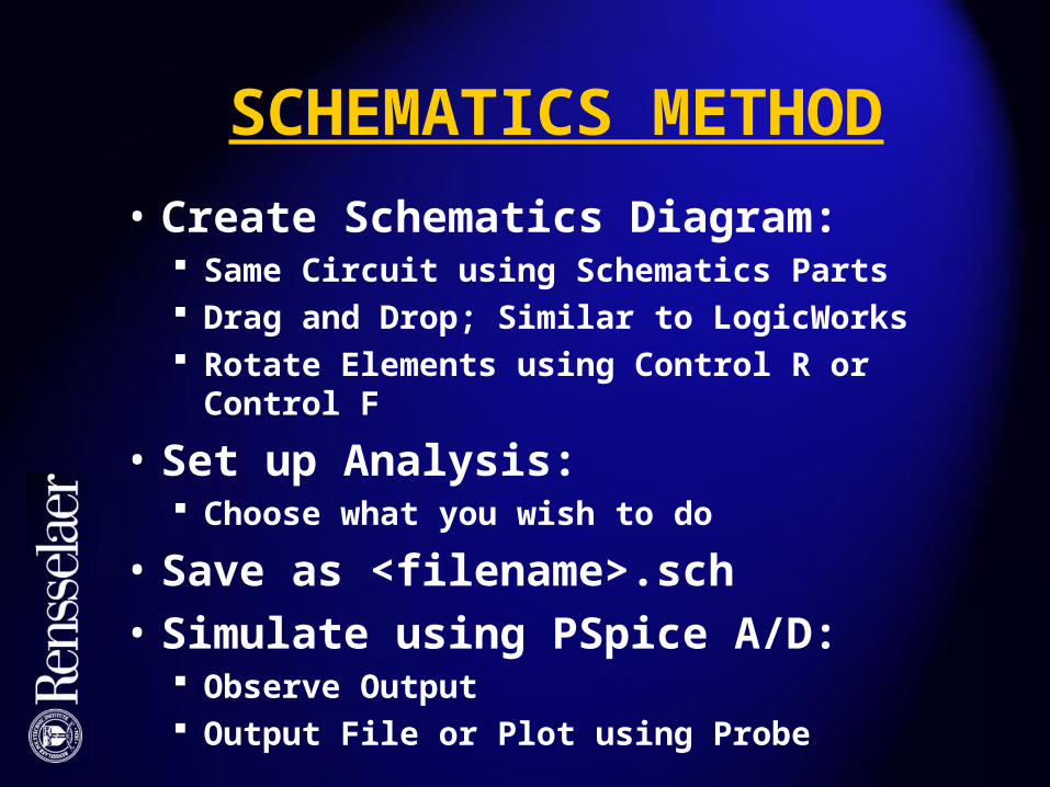
• Create Schematics Diagram: Same Circuit using Schematics Parts Drag and Drop; Similar to LogicWorks Rotate Elements using Control R or Control F
• Set up Analysis: Choose what you wish to do
• Save as <filename>.sch
• Simulate using PSpice A/D: Observe Output Output File or Plot using Probe
ACTIVITY 3-1
Schematics Diagram

SCHEMATICS METHOD
• Open Schematics: Select New Locate “Parts”; Drag and Drop Sources are Passive Elements in PSpice!
Must put in i = -1 A to get +1 A Add Wires using Wire Icon Must always include Earth Ground! Change Names and Values of Elements by
Doubleclicking on them Save as <filename>.sch
SCHEMATICS METHOD
• Under “Set up Analysis” Icon: Select DC Sweep of Current Source, -1 to +1 A Will use other options later
• Click “Simulate” Icon: Error Messages if Errors Observe Output Same as before except for Sign Change Horizontal Axis to –i to get positive slope Much Quicker once you get used to it
MULTIMETER MEASUREMENTS
• Model for Real Voltmeter: Ideal Voltmeter in Parallel with RM
Ideal Voltmeter Draws No Current RM = “large”; Typically a few Mohms
• Model for Real Ammeter: Ideal Ammeter in Series with Rm
Ideal Ammeter has no voltage drop Rm = “small”; Typically a few ohms

VOLTMETER
VMR
i 0
VMR Voltmeter Resistance
Large (few M 's)

AMMETER
AMR Ammeter Resistance
Small (few 's)
AMR
v 0
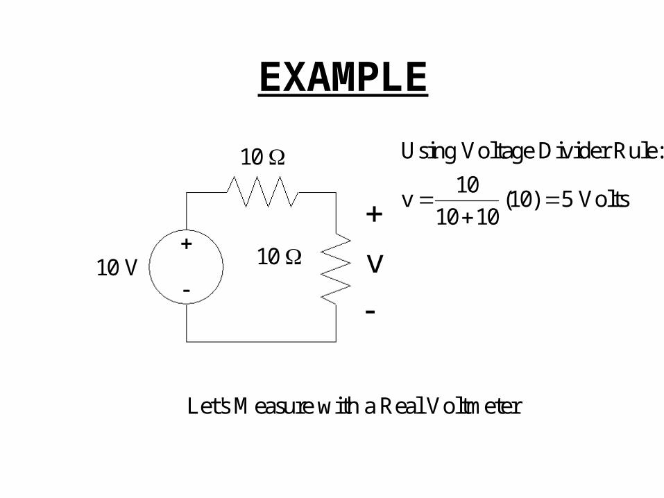
EXAMPLE
10 V
10
10 v
Using Voltage Divider Rule:
10v (10) 5 Volts
10 10
Let's Measure with a Real Voltmeter
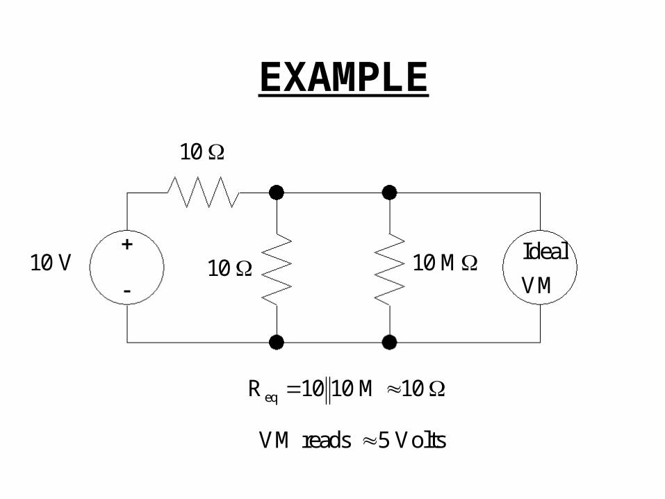
EXAMPLE
10 V
10
10 10 M Ideal
VM
eqR 10 10 M 10
VM reads 5 Volts

EXAMPLE
10 V
10 M
10 M 10 MIdeal
VM
eqR 10 M 10 M 5 M 5
VM reads (10) 3.33 Volts5 10
Meter affects the measurement
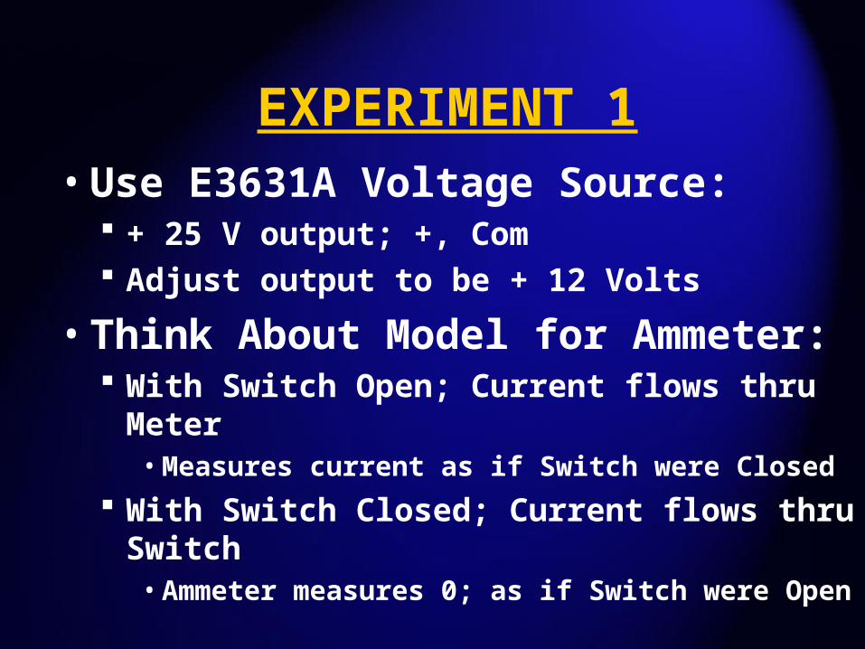
EXPERIMENT 1• Use E3631A Voltage Source:
+ 25 V output; +, Com Adjust output to be + 12 Volts
• Think About Model for Ammeter: With Switch Open; Current flows thru Meter• Measures current as if Switch were Closed
With Switch Closed; Current flows thru Switch• Ammeter measures 0; as if Switch were Open
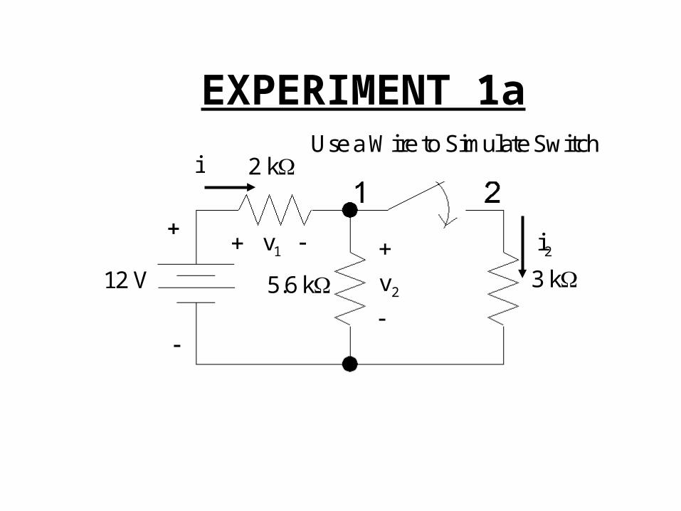
EXPERIMENT 1a
12 V
2 k
5.6 k 3 k2v
1 v 2i
iUse a Wire to Simulate Switch
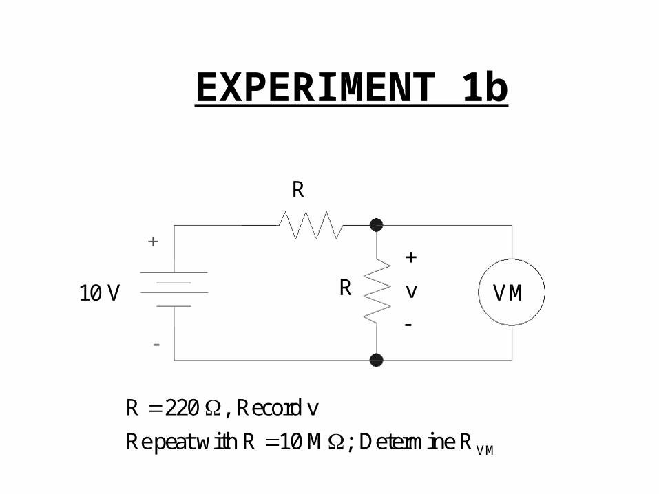
EXPERIMENT 1b
10 V
R
R VM
VM
R 220 , Record v
Re peat with R 10 M ; Determine R
v


