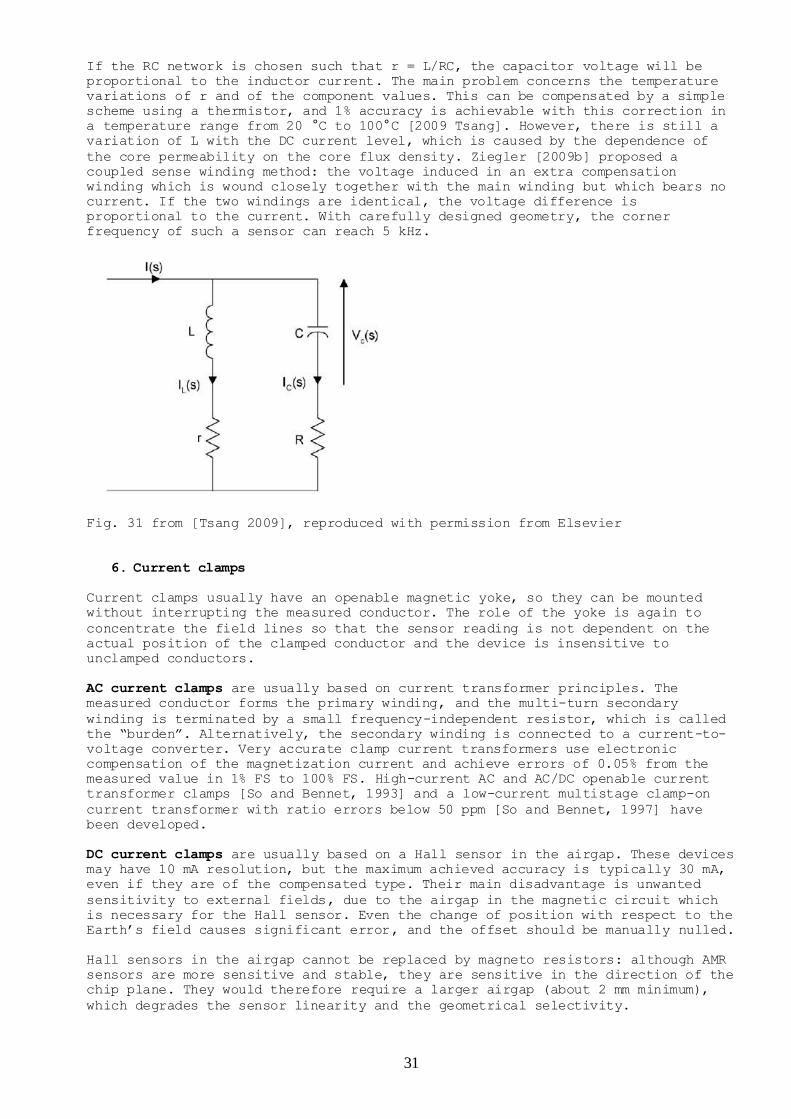
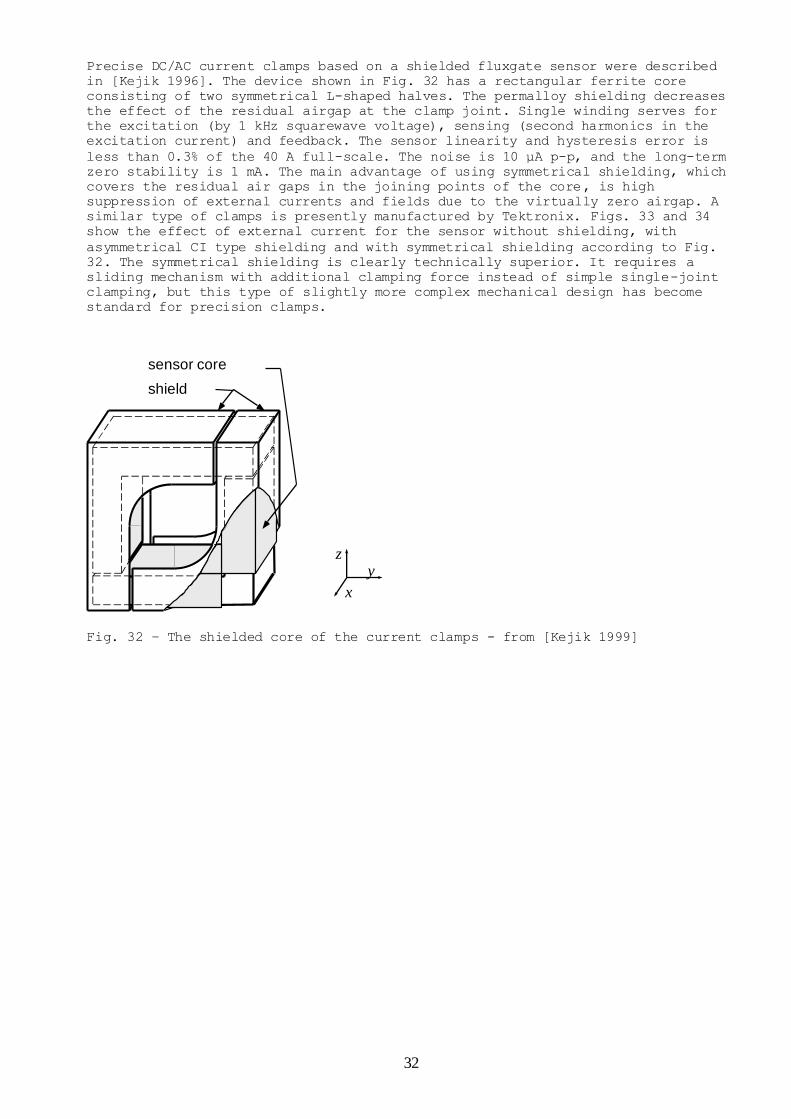
1 Ripka, P. Electric Current Sensors: a Review Preprint Measurement Science and Technology. 2010, 21(11), 112001-112024. Electric current sensors: a review Pavel Ripka, Czech Technical University in Prague, Czech Republic Abstract The paper makes a brief overview of traditional methods of measuremet of electric current and shows in more detail relatively new types of current sensors. These include Hall sensors with field concentrators, AMR current sensors, magnetooptical and superconducting current sensors. The influence of the magnetic core properties on the error of the current transformer shows why nanocrystalline materials are so advantageous for this application. Built-in CMOS current sensor are important tools for monitoring of the health of integrated circuits. Of special industrial value are current clamps which can be installed without breaking the measured conductor. Parameters of current sensors are also discussed, including geometrical selectivity. This parameter specific for current sensors means the ability to suppress the influence of currents external to the sensor (including the position of return conductor) and also suppress the influence on the position of the measured conductor with respect to the current. Key words Hall current sensor, current transformer, AMR current sensor, current shunt, ammeter, Rogowski coil, current comparator, CMOS current sensor, magnetooptical current sensor, SQUID current sensor, GMI, current clamps 1. Introduction Precise DC and AC current sensors are required by the automotive industry and by the chemical industry for measuring power and energy, and in many other applications. We discuss the principles of these devices with special reference to recent advances. We will concentrate on factors influencing precision, geometrical selectivity and other parameters important for new applications, e.g. inverters for power mills, intelligent buildings and big technological or physical experiments, e.g. electron beam measurement in the ATLAS experiment at CERN. Classical current sensors were reviewed in [Iwansson 1999]. Most contactless current sensors are based on magnetic field sensors – these were reviewed in [Ripka 2001], and more recently in [Edelstein 2007]. The latest review of current sensors provides an excellent overview of the principles and properties of industrial devices available on the market [Ziegler 2009a]. In the present paper we concentrate on the latest research developments and laboratory devices. 2. Overview of current measurement 2.1 Definition and standards Electric current is caused by movement of charge, and in the older MKS system it was therefore naturally defined as a derived unit. In the present SI unit system, the ampere is the fundamental unit [BIPM]. The early (1908) definition of an ampere was electrolytic. This was replaced in 1948 by a force definition. Using this definition, the ampere can be realized using the current balance. The most precise definition is the Watt current balance, which is also used to realize the “electronic kilogram”: a relative uncertainty of 3.6×10 −8 was achieved by the U.S. National Institute of Standards and Technology (NIST) [Steiner 2007]. A much more practical realization of the ampere is via Ohm's law from the volt and the ohm,
Transcript
1
Ripka, P. Electric Current Sensors: a Review Preprint Measurement Science and Technology. 2010, 21(11), 112001-112024.
Electric current sensors: a review Pavel Ripka, Czech Technical University in Prague, Czech Republic
Abstract The paper makes a brief overview of traditional methods of measuremet of electric current and shows in more detail relatively new types of current sensors. These include Hall sensors with field concentrators, AMR current sensors, magnetooptical and superconducting current sensors. The
influence of the magnetic core properties on the error of the current transformer shows why nanocrystalline materials are so advantageous for this application. Built-in CMOS current sensor are important tools for monitoring of the health of integrated circuits. Of special industrial value are current clamps which can be installed without breaking the measured conductor.
Parameters of current sensors are also discussed, including geometrical selectivity. This parameter specific for current sensors means the ability to suppress the influence of currents external to the sensor (including the position of return conductor) and also suppress the influence on the position of the measured conductor with respect to the current.
Key words Hall current sensor, current transformer, AMR current sensor, current shunt, ammeter, Rogowski coil, current comparator, CMOS current sensor, magnetooptical current sensor, SQUID current
sensor, GMI, current clamps
1. Introduction Precise DC and AC current sensors are required by the automotive industry and by
the chemical industry for measuring power and energy, and in many other
applications. We discuss the principles of these devices with special reference
to recent advances. We will concentrate on factors influencing precision,
geometrical selectivity and other parameters important for new applications, e.g.
inverters for power mills, intelligent buildings and big technological or
physical experiments, e.g. electron beam measurement in the ATLAS experiment at
CERN.
Classical current sensors were reviewed in [Iwansson 1999]. Most contactless
current sensors are based on magnetic field sensors – these were reviewed in
[Ripka 2001], and more recently in [Edelstein 2007].
The latest review of current sensors provides an excellent overview of the
principles and properties of industrial devices available on the market [Ziegler
2009a]. In the present paper we concentrate on the latest research developments
and laboratory devices.
2. Overview of current measurement
2.1 Definition and standards Electric current is caused by movement of charge, and in the older MKS system it
was therefore naturally defined as a derived unit. In the present SI unit system,
the ampere is the fundamental unit [BIPM]. The early (1908) definition of an
ampere was electrolytic. This was replaced in 1948 by a force definition. Using
this definition, the ampere can be realized using the current balance. The most
precise definition is the Watt current balance, which is also used to realize the
“electronic kilogram”: a relative uncertainty of 3.6×10⁻⁸ was achieved by the U.S.
National Institute of Standards and Technology (NIST) [Steiner 2007]. A much more
practical realization of the ampere is via Ohm's law from the volt and the ohm,
2
which are easily reproducible using the Josephson junction and the quantum Hall
effect [BIPM, Appendix 2].
The proposed new definition of the ampere is a return to the natural concept
based on elementary charge and time.
National metrology institutes offer calibration of current sensors with minimum
expanded uncertainty (a coverage factor of 2, i.e. for 95% level of confidence)
of typically 10 µA/A for DC currents and 100 µA/A for AC currents. The AC current
ratio is calibrated with minimum expanded uncertainty of 5 ppm in ratio error and
5 µrad in phase displacement.
2.2 Current shunts The disadvantages of current shunts are obvious: the measured current has to be
interrupted to introduce the sensor, shunts for large currents are bulky, they
dissipate heat and the output is galvanically connected with the measured
circuit. However current-sensing resistors are a robust and cheap solution for
many applications. Self-made coaxial current shunts can easily be made from a set
of metal resistors in parallel [Filipski 2006, 2008].
If precision is not a critical consideration, the current can be measured even
through the voltage drop across a current-carrying copper trace. A
microcontroller was used to calibrate the copper trace resistance and implement
temperature drift compensation by means of a temperature sensor [Ziegler 2000c].
Corrections should be made for the thermal resistance between the busbar and the
temperature sensor. The authors have shown that the dynamic properties of this
sensor are not due to the self-inductance of the busbar, but due to the mutual
inductance between the main loop and the sense loop.
In order to measure very small currents, the value of the current sensing
resistor should be increased so that the measured drop is measurable. This leads
to problems. A systematic error is caused by a divider consisting of the source
internal resistance and the sensing resistor. High value resistors have poor time
and temperature stability, they are noisy and, together with the input
capacitance of the voltage amplifier, they create a large time constant which may
slow down the measurement.
The noise sources are shown in Fig. 1.
Fig. 1.Sources of current errors – from [Keithley 2007]
The noise current generators ICE, ISE, and IIE in the above model represent
unwanted currents generated at a particular point in the circuit. These currents
may arise from triboelectric, piezo-electric and electrochemical effects, or from
resistive leakage or dielectric absorption (Fig. 3).
3
Fig. 2 Typical magnitudes of currents generated by low current phenomena – from
[Keithley 2007].
For measuring picoamps and lower currents, a current-to-voltage configuration is
preferred.
2.3 Current-to-voltage converters This circuit is also referred to as a feedback-type ammeter (Fig. 3)
Fig. 3 Current-to-voltage converter – from [Keithley 2007] The range is changed by output divider RA, RB rather than by changing the
feedback resistor RF. Supposing that RF >> RA, RB we may write for the output
voltage:
Vout= - IRF(1+RA/RB)
The parasitic capacitance of the feedback resistor CF, which limits the speed,
can be effectively compensated by the circuit shown in Figure 4. If time constant
R1C1 is made equal to time constant RFCF, the shaded area of the circuit behaves
exactly like resistance RF with zero CF. The matching of the time constants in
this case is fairly straightforward, because the capacitances involved are all
constant and are not affected by the input capacitances [Keithley 2004].
4
Fig 4 from [Keithley 2004].
A simple current-to-voltage converter with an amplification factor up to 1V/nA
can be built using off-the-shelf operational amplifiers. A converter based on
OPA129 (Texas Instruments) has a 100 fA bias current [Weckenmann 2008]. Other
picoammeters are based on AD549L (Analog devices) with a bias current of 40 fA
and noise of 0.36 fA p-p in the 0.1 Hz to 10 Hz bandwidth [Northrop 2005]. The
noise has a 1/f character, so 0.1 fA/√Hz@1kHz increases to 10 fA/√[email protected]. These
are extraordinary values compared to the 4fA/√Hz noise of superconducting current
amplifiers [Gay 2000].
It is sometimes easier to measure small currents by integrating them (using a
coulomb meter). In this case, the feedback resistor is replaced by an integrating
capacitor, which is theoretically noiseless. The charge method is preferable
when current resolution below 1fA is required, as values of Rf>1012 are very
impractical.
The achievable current resolution of available ammeters is 10 fA. Smaller
currents can still be measured with conventional instruments, but the measurement
is slow in order to average out the instrument noise. Superconducting current
sensors may be much faster, but the fundamental speed limit of all current
measurements is set by the fact that 1 aA corresponds to 6 electrons/sec.
3. Current sensor parameters The basic parameters of any sensor are linearity, offset (for DC sensors) and
sensitivity, and also stability of offset and sensitivity with temperature and
time. Also important is the sensor bandwidth (of more generally frequency
characteristics, as current waveforms often contain high frequency component.
Current sensors which contain ferromagnetic material also suffer from hysteresis
and perming (change in offset after the sensor is subjected to the large
overcurrent from a magnetic field shock). It is also important for contactless
sensors to be insensitive to the actual position of the measured conductor and
also resistant to external currents and magnetic fields. We call this parameter
“geometrical selectivity”, and consider it to be critical for most applications.
The most common way to achieve geometrical selectivity is to use a closed
magnetic circuit with a measured conductor inside. This is used in current
transformers, fluxgate current sensors and in most Hall current sensors. The
high-permeability magnetic circuit (the yoke is often in the shape of a ring)
concentrates all field lines from the measured current, so that the measured flux
in the magnetic circuit does not depend on the actual position of the conductor.
In thiscase, H in the yoke central line l is constant, and we can write
Hl = NI,
where I is measured current and N is number of turns. The magnetic circuit also
shields against external fields. It is important to use a high cross-sectional
5
area of the magnetic material to keep a high demagnetisation factor against
external fields.
The magnetic yoke should not be saturated, i.e. l>NI/Hsat. This means that the
magnetic circuit becomes very large for high measured currents. Airgaps can be
introduced, but these degrade the geometrical selectivity. Another approach is to
compensate the measured current using a multi-turn coil. However, generating the
compensation current requires power.
Magnetic gradient techniques can be used if the power or space limitations do not
allow the use of a yoke. Simple integrated current sensors use a folded conductor
and a gradient field sensor. This suppresses the response from distant sources,
giving a low gradient. For large currents, the current bar should be kept
straight, and circular arrays of typically four to eight sensors are used [Di
Rienzo 2003]. Averaging the sensor output increases the sensitivity to the
conductor between them and decreases sensitivity to conductors outside. Instead
of simple averaging of the sensor outputs, more sophisticated signal processing
methods have been developed to suppress the effects of nearby false currents more
effectively [Bazzocchi 2000].
The best magnetic circuit for a current sensor is a toroid made from high
permeability material without an airgap. This is used in current transformers and
in some residual current sensors. However, even a toroid cannot be considered as
ideally homogeneous: as it is often wound from tape material, and the beginning
and end of the strip cause significant asymmetry. Another problem may arise from
the presence of airgaps between the layers. They may cause concentration of the
flux to the first layer, which can be saturated. These errors are not only of
concern in the case of precise sensors, such as current comparators – they may
cause abnormal tripping of ordinary current breakers [Colin 2006].
Wide bandwidth: a large frequency range from DC to several MHz is required for
applications in switching power converters.
High dynamic range and resistance against overload is another important
parameter. Accuracy is often required even for a small fraction of the full-
scale. One example is the requirement to measure the current consumption of the
house in the standby mode and during full operation.
Immunity against dV/dt is critical for use in modern power modules. Current
sensors located close to fast-switching transistors can be subjected to
transients of 10 kV/µs. Such transients can be coupled by parasitic capacitances
to the output of the current sensor. Proper electrostatic shielding can
efficiently suppress this effect, but it complicates the design of the sensor.
Low cost and high environmental resistance is a must for industrial sensors.
4. Applications and demands
Current sensors are required for numerous applications, including
Current leakage monitoring.
Industrial applications – large AC and DC currents.
Car applications: special requirements for hybrid cars.
House automation.
Energy production, conversion and storage
Motor drives, power converters and power modules
Current sensors embedded in ICs
We only briefly mention specific issues in connection with the last two
applications
4.1 Power converters and power modules Current sensors are essential for the control of power converters. They are
normally used for current programming and overcurrent protection. Input and
output voltages are usually used for the control. In the case of galvanically
insulated converters, optocouplers are often used to insulate one of these
voltages. Limited linearity of optocouplers can be a problem in converters with
wide variation of output, e.g. DC/AC converters. Qiu [2003] has shown that the
whole converter can be controlled using only current information, so that voltage
6
sensors are not necessary. This approach can simplify the design of galvanically
insulated power converters.
Bai [2003] suggests the use of magnetooptical current sensors for applications in
integrated power modules. The most promising candidates are sensors using rare-
earth iron garnet sensing material between two optical fibres. Although the
concept was proven to work, it is at present not cost-effective.
4.2 Built-in current testing and embedded sensors
The built-in CMOS current sensor (BICS) was designed to monitor the current
consumption (IDD) of integrated circuits, as it is a simple method for detecting
defects missed by conventional logic tests [Cimino 2007].
The sensor uses a parasitic 10 Ω resistor in the IC interconnecting layer; the
effect of the process parameter variation is reduced by a ratiometric circuit.
The circuit is able to measure 20 mA current with 0.5% accuracy. Although the
measured current is reduced by a factor of 10 using a current mirror, the sensor
consumes 2 mW power, which may be unacceptable for some applications. A possible
solution is to employ a switching structure which bypasses the current-to-voltage
conversion transistors for most of the operational time, and performs the test
only on demand. This allows a current sensing structure to be built with power
consumption in the order of µW, which does not cause significant speed
degradation of the measured circuit [Kim 2006]. Another way is to use dynamic
switching: the switch between the supply voltage and the circuit under test (CUT)
is open, and the decaying voltage is observed. The time that the voltage takes to
drop to the reference level is measured by the counter. Very fast measurement
with 1 µA resolution is achievable using this technique [Vazquez 2004].
The radiation sensitivity of VLSI devices has become an important issue, as these
circuits are sensitive not only to cosmic rays, but also to the atmospheric
neutrons and protons present at low altitudes and to natural alpha particles.
Bulk BICS can detect the transient currents generated by the impact of an
energetic radioactive particle at a sensitive circuit node of an integrated
circuit [Wirth 2008]. Donoval [2007] suggested the use of a MAGFET transistor for
embedded current monitoring, but this research is at the very beginning.
The current sensor structure can be embedded into the lateral insulated-gate
bipolar transistor (IGBT) structure. 5% accuracy is achievable over a wide
temperature range, which is sufficient for overload and short-circuit protection
[Liang 2003].
5. Contactless sensor principles Current measurement using a shunt resistor is impractical or impossible in some
cases. Contactless current sensors keep galvanic insulation between the measured
current and their output voltage. A wide range of AC and DC contactless current
sensors are produced by LEM, F.W. Bell, VAC, Honeywell, Telcon and many other
manufacturers. Magnetic field sensors can be used to measure currents in remote
conductors at high potentials, in underground cables and in building structures.
5.1 Instrument current transformers
A current transformer (CT or ICT) usually has a bulk ring core made of high-
permeability material. For currents higher than 50 A the primary winding is
usually a single conductor through the core opening. The secondary winding should
ideally be short-circuited; however for most applications it is connected to a
small ‘burden’ resistor or impedance. The core is wound with high permeability
tape (for low-frequency devices) or is made from ferrite (for high-frequency
current probes). In some devices, the secondary current is measured by active
current-to-voltage converted in such a way that the burden is virtually zero.
Later we will show that this leads to smaller error, as the transformer core
works at lower flux density.
Current transformers are also made with an openable core, most often as AC
current clamps for oscilloscopes or multimeters.
Current transformers are very popular devices:
- they are very simple and robust
7
- they do not require external power
- they have high galvanic insulation
- they are cheap
- they have a long lifetime with invariant parameters
CTs should be periodically calibrated. This is usually performed using a standard
CT and a current comparator (Chapter 4.4.) Fully automated transformer
measurement sets are available on the market (e.g. Tettex 2767).
National metrology laboratories usually calibrate current transformers with a
nominal secondary current of 5 A or 1 A, with test points of (1; 5; 20; 100 &
120)% of rated primary current. Routine tests are performed at 50, 60 and 400 Hz
with uncertainties of 0.01% in ratio error and 0.1 mrad in phase angle
displacement. Less accurate on-site calibration can be carried out using a
Rogowski coil and a coaxial shunt resistor [Suomalainen 2009].
Calibration equipment based on current comparators is bulky and expensive.
Brandolini [2009] proposed a novel method based on digital processing of signals
that are directly collected at the secondaries of the transformers under test and
a reference transformer. The errors of the proposed system are also almost
constant for an input signal with a frequency of up to 1 kHz. When compared to
Tettex 2767, the achieved uncertainty at 50 Hz was below 0.013% in amplitude and
0.16 mrad in phase. At higher frequencies up to 1 kHz, the error was below
0.025%/1.3 mrad. This means that even if this instrument does not achieve the
precision of a current comparator, it can be used to calibrate a 0.1 precision
class electronic measurement transformer, as defined by the IEC 60044-7 and IEC
60044-8 standards.
Fig. 5 shows the equivalent circuit of the current transformer for low and medium
frequencies
I1 R1 L1 L2
I01
Vi Rc IR Lm
IL
CpV1
IC
R2I2
Z2V2
Fig. 5 after [Draxler 2007]
R1, R2, L1 and L2 represent resistances and leakage inductances of primary and
secondary windings,
Rc is the resistance representing losses in the ferromagnetic core,
Lm is the magnetizing inductance,
Cp represents the parasitic capacitances of the winding,
Z2 is the burden
and IL+IR is the magnetization current
This equivalent circuit is valid for a 1:1 current ratio. For other current
ratios, the circuit parameters can be recalculated either to the primary side or
to the secondary side. Currents and voltages are recalculated by the turn number
ratio N, and impedances are recalculated by N2.
At low and medium frequencies, the influence of parasitic capacitances and
leakage inductances can be neglected, and a simplified phasor diagram according
to Fig. 6 can be used.
8
Vi
I2
I1
Im
IR
IL m
Fig. 6 after [Draxler 2007]
Im is magnetizing current of CT, consisting of components IR and IL,
Φ is magnetic flux of core,
δ is loss angle of the ferromagnetic core,
δI is CT phase displacement,and
β is the phase displacement of the secondary burden (which is often negligible).
For a properly working CT the phase error δI is small and, according to Fig. 7,
we can write for the amplitude and phase errors:
(%) 100
sin100
11
12
I
ImI
I
II
)(
cos
1
radI
Itg m
II
Im
I2
I1
Fig. 7 after [Draxler 2007]
It is clear that in order to keep the error low at low frequencies, it is
important to keep Rc and Lm high and also to keep R2 and Z2 small. The magnetizing
inductance Lm is given by
9
r
AN
l
ANL Cr
C
Crm
2
2
0
2
0
where r is the mean radius of the toroidal core
and Ac is the cross-sectional area of the core.
Lm is kept high when using a high permeability core with a high number of turns.
As the inductance depends on the square of the number of turns N2 and the wire
resistance depends only on N, a 1:5 turn ratio gives a larger error than 10:50.
By increasing the number of turns we can bring the core to saturation: this
should be avoided by using a higher-diameter ring. The main inductance also
depends linearly on the cross-sectional area of the core. For this reason,
precise CTs are large.
At low frequencies (such as 50/60 Hz), the dominant source of error is the
magnetizing current, which is inversely proportional to the frequency. The
following methods can be used to reduce this current:
- use a core material with high permeability
- increase the core area
- increase the number of turns
- virtually increase the core permeability by a feedback amplifier (used in
self-balancing current comparators)
The magnetizing inductance Lm, together with secondary resistance R2 and burden
resistance R, form a high-pass filter circuit. Another approach to improve
transformer accuracy at low frequencies is therefore to decrease the burden
resistance R, which can be done by using a current-to-voltage converter [Kondrath
2009].
Some CTs have almost a constant ratio error for a wide range of measured
currents. In this case, the error can be compensated for by adding extra turns to
the secondary winding. This is called turn error compensation. Transformers with
such compensation show anomalous behaviour – their error increases when the
burden decreases. Magnetization of the CT core (e.g. due to a lightning strike)
may also lead to increased errors when the measured current is small so that the
CT core is not demagnetized [Draxler 2007].
Electronically enhanced current transformers
The first step is to connect the output of the CT to a current-to-voltage
converter with a very small input resistance. This will minimize the burden, and
it keeps the flux in the CT core at a low level, but not at zero – this is clear
from the equivalent circuit of the CT in Fig. 5. In order to achieve really zero
flux, it is necessary to keep Vi = 0, and not only V2 = 0. This can be achieved by
a simple analog circuit [Baccigalupi 2009]. The test was performed with a low-
cost CT with a ferrite core: at 50 Hz and also for higher frequencies up to 450
Hz the ratio error was reduced from 2% to 0.7%. The phase error was reduced from
45 mrad to 3 mrad at 50 Hz, but this error increased linearly with frequency due
to the delay in electronic circuits. It should be noted that this type of
enhancement does not work properly for CT with turn error compensation.
Electronically enhanced two-stage current transformers show accuracy improvement
by two orders of magnitude: with a low burden, the resulting error is below 10
ppm [Miljanic 1991]. These devices can also indicate the remanence of the
transformer core or DC component in the primary current, which may degrade the
performance of a classical current transformer; they may have a lower number of
turns, which avoids problems with parasitic capacitances and enables the device
to be used at higher frequencies; and finally the volume of the core may be
reduced.
10
Amplifier-aided wide-band two-stage current transformers may have 1 ppm accuracy
from 50 Hz up to 1 kHz, and 15 ppm accuracy up to 10 kHz [Souders 1972].
At higher frequencies, parasitic capacitances between the turns and layers of the
winding are the dominant source of error. Here, increasing the number of turns
increases the error. For precise fast-current transformers, amorphous cobalt-
based cores or ferrite cores are used, which give high permeability at MHz
frequencies. Such transformers are used to observe short beam pulses in particle
accelerators. [Bergoz] manufactures transformers with cut-off frequencies up to 2
GHz.
A high-frequency model of a current transformer is given in Fig.8 [Kondrath
2009]. It is shown that the effect of Lm, R1 and L1 can be neglected. We also
neglect the inductance of the sensing resistor. The frequency bandwidth is
usually given by the first pole fp1=1/2πR2C. A second pole, defined by stray
inductance fp2=Rc/2πL2, is normally at a much higher frequency.
Rc C
I2
V2
L2
R2
Fig. 8 High-frequency equivalent circuit of the current transformer – after
[Kondrath 2009].
There have also been efforts to digitally compensate the frequency dependent
errors of current transformers. If the current transformer is considered to be a
linear system (which is often true for low burdens), its frequency
characteristics can be identified and corrected using a frequency filter with
inverse characteristics. An efficient way to build this type of filter is with
the use of FPGA (Field-programmable gate array). Both the amplitude and the phase
error of a low-cost current transformer with an accuracy class of 0,5 was reduced
by a factor of 20 [Gallo 2009]. Such a solution can be cost-effective, due to the
very low cost of digital hardware. A disadvantage is that digital electronics
introduces an inevitable time delay. If this cannot be eliminated by post-
processing, it will lead to large, frequency-dependent phase error.
Current transformers are often used in electronic watt and energy meters. For
this application, it is very important to make them resistant against saturation
– either from a strong permanent magnet, or due to a DC component in the measured
current [Mlejnek 2009]. Possible methods for avoiding such saturation are:
1. use flat-loop magnetic material, which has a very high saturation field H
2. use composite cores, consisting of a high-permeability ring for precision and
a low-permeability ring for saturation immunity
3. detect saturation by other means
4. use a Rogowski coil instead of a CT, which has no magnetic core
The composite high-permeability core gives low angular and amplitude error for
most applications, but this is not guaranteed for all types of loads. Flat-loop
materials such as Vacuumschmelze VAC do a better job, but these materials are
expensive. It was recently shown that some cheap low-permeability rings can also
be used for this application: they have a relatively large phase shift, but it is
constant over the wide range of measured currents and can therefore be
compensated [Mlejnek 2007, 2009b].
Fe-based nanocrystalline alloys are promising materials for very precise small-
size current transformers [Draxler 1996]. They may have the same permeability as
permalloys (NiFe crystalline alloys) or Co-based amorphous alloys, but they have
11
much larger saturation induction, so that instr)ument current transformers are
smaller. Properly prepared Fe-based nanocrystalline ring-cores may have almost
constant permeability over a wide range of induction. This gives a low amplitude
error and a constant phase error in a wide range of the measured current. Such a
constant phase error can easily be compensated. In large amounts, Fe-based
nanocrystalline materials can be purchased at competitive prices.
5.2 Rogowski coil
The Rogowski coil for measuring current is an air coil wound around the measured
current conductor. The basic operating principle is given by the mutual
inductance M between the primary (single turn) and the secondary (many turns).
The output voltage is proportional to the derivative of the current:
u = M(dI/dt)
The coil should be precisely manufactured with constant winding density and
diameter. Ideally, a homogeneous coil has excellent geometrical selectivity, i.e.
it is insensitive to external fields and to the position of the measured
conductor), as it follows Ampere’s law in the open air:
C
CildB 0
where the integration path C is the central line of the coil (usually a circle).
In order to obtain the AC current waveform, a Rogowski coil is used together with
an integrator. Single-chip digital integrators have been developed to process the
signal of Rogowski coils (also known as dI/dt sensors) for energy meters. The use
of an AD 7759 signal processor with built-in sigma-delta A/D converters gives
0.1% error from the measured value in the 1000:1 dynamic range [Koon 2009].
The Rogowski coil contains no ferromagnetic material, and thus it has excellent
linearity and an extremely large dynamic range. Users often rely on their
linearity and use them to measure currents that are much higher than the currents
used for calibration. Care should be taken with the geometry of the connecting
bus bars and the return conductor to reduce the effect of magnetic coupling.
The Rogowski coil can be very simply temperature compensated. With increasing
temperature the coil former expands, causing about 50 ppm/K temperature
coefficient of the scale factor. However, the resistance of the copper coil
increases with a 3900 ppm/k temperature coefficient. By connecting a proper low-
temco resistor in parallel to the Rogowski coil, we create a voltage divider
which compensates the thermal expansion. The resulting temperature coefficient
can be as low as 2 ppm/K [Suomalainen 2009].
Stationary Rogowski coils are used to measure AC or transient currents or changes
in DC currents. For long-term measurements, the limiting factor is the offset
drift of the integrator. It is also possible to measure DC current with an
openable Rogowski coil: the output voltage is integrated while the coil is closed
around the measured conductor.
Flexible Rogowski coils can be easily wound on top of a plastic cable with thick
insulation, such as a coaxial cable with removed shielding. The inside conductor
is used as a return loop, which compensates the perpendicular virtual loop
created by the winding advance. An uncompensated loop would cause sensitivity to
external magnetic fields in the axial direction. A detailed description of the
production and testing of such coils and the following integrator and filter can
be found in [Abdi-Jalebi 2007]. The error caused by the off-center position of
the measured current was below 1.5%, and the suppression of the external currents
was better than 100.
12
V(t)
Fig. 9 A Rogowski coil in PCB technology. Each layer is wound in the opposite
direction to compensate for the loop created by turn advancement -
after Kojovic 2002
Rogowski coils are useful for measuring transient currents. The coil self-
inductance and the parasitic capacitance form a resonant circuit. In order to
increase the resonance frequency of this circuit, a lower number of turns should
be used, which decreases the sensitivity. 1 to 3 MHz resonance frequency is
typical for flexible coils, while multiturn solid coils may have resonance as low
as 50 kHz. At high frequencies, the active integrator can also cause errors due
to the limited bandwidth and slew-rate of the amplifier. An alternative technique
for extending the frequency range is to use the current output instead of
integrating the output voltage [Ward 1993].
Printed circuit board (PCB) technology was used to produce Rogowski coils with a
more precise geometry and improved temperature stability. To compensate the
virtual perpendicular loop, two PCB coils with opposite winding directions are
connected in series. In order to achieve perfect compensation it is important to
design these two coils with the same diameter, as shown in Fig. 9.
An improved twin-loop PCB Rogowski coil with a transfer ratio of 4V/400kA was
used to measure the plasma current in the Tokamak. Thanks to good homogeneity of
the winding, the change in the transfer ratio with the geometrical location of
the measured current inside the measuring channel is less than 2%. This is very
important for this application, as the exact location of the plasma current in
the 1 m diameter vacuum vessel is unpredictable [Qing 2009]. In this design, both
coils are made in the same place, which means that one of them has a smaller
diameter and thus the sensitivity to axial fields is not perfectly compensated.
Bull [2005] presented a hybrid Rogowski current sensor for high-voltage
applications. The device consists of a Rogowski coil with a passive integrator
connected to an Integrated-Optic Pockels Cell (IOPC). This passive cell was
developed for electric field sensing. Here it is used to modulate the light
brought in and out by two optical fibres. The high-voltage part requires no
electricity supply. The device has 0.3% accuracy for currents up to 30 kA in the
range from -30 to +70°C.
5.3 DC current transformers and current comparators Classical current transformers naturally measure only AC currents. DC current
transformers and DC current comparators (Section 4.4) use the fluxgate effect in
a core which is periodically saturated by the excitation field. If no DC current
is present, the core flux and also the voltage induced into the detection winding
contain only odd harmonics. DC current shifts the magnetization characteristics,
and the flux waveform is no longer symmetrical. This induces even harmonics
proportional to the measured DC current. The first sensors of this type were
transductors [Bera 2003]. Modern DC current transformers use phase-sensitive
detectors to extract the second harmonics from the induced voltage.
13
The accuracy of a typical commercial 40 A DC current transformer is 0.5%,
linearity 0.1%, current temperature drift <30mA (-250C..700C) [Ripka 2004]. A
self-oscillating sensor of this type is described by Ponjavic and Duric [2007].
The first fluxgate current sensor in PCB (printed circuit board) technology was
described in [Belloy 2000]. Its sensor had a single winding of 36 turns over a
toroidal core made of amorphous magnetic tape. It achieved 10 mV/A sensitivity
and ranges up to 5 A. A prototype of a fluxgate current sensor with an
electroplated core in PCB technology was described in [Ripka 2005]. Short
excitation pulses should be used in order to lower the excitation power. This can
be achieved using a tank circuit with an external saturable inductor [Tang 2004].
Another geometry for a pcb fluxgate current sensor with an electroplated core was
used by [O'Donnell 2006].
Because of their low offset drift, fluxgate-based “DC current transformers” are
superior to current sensors that have a Hall sensor in the airgap. A disadvantage
is the large power consumption of these devices.
A simple integrated overcurrent sensor was described in [Fujiyama 1997]. The
sensor is similar to a DC current transformer, but the excitation current does
not saturate the ring core. Once the core is saturated by the measured current,
the output voltage drops to zero.
4.3.1 Current comparators
Current comparators are described in a classical book written by Miljanic and
Moore [Moore 1998].
An AC current comparator is a passive device which has three windings on a ring
core: primary, secondary and detection (Fig. 10). If the primary and secondary
currents are balanced, i.e. N1I1 = N2I2, the core flux and also the voltage Vd
induced into the detection winding is zero. AC comparators serve as national
standards of current ratio, and they are used for calibrating standard current
transformers. Practical devices are large and complex: the differences between
N1I1 = N2I2 are compensated by additional windings Nε and Nφ, and they have several
active and passive shieldings to reduce errors. AC comparators have errors below
1 ppm in amplitude and 310-6 deg in phase.
dV
L1I
K1I
I I
1I
k2I
l2I
N N
1N 2N
dN
2I
NR
1P 2P RC
Fig. 10 AC current comparator (will be redrawn)
DC current comparators are precise devices based on the fluxgate effect. The core
consists of two detection ring cores excited in opposite directions by the
excitation winding Nexc supplied by current generator G (Fig. 11). The second
harmonic component of the voltage induced into the detection winding N is
measured by phase sensitive detector PSD. The output from PSD is filtered and
amplified, and controls the DC compensation current I2. In the ideal case N1I1 =
N2I2 and the device output is derived from I2 using shunt resistor R. Only one
layer of magnetic shielding under the secondary winding is shown in the figure.
The role of this shielding is twofold: it reduces the leakage fluxes originating
14
from the non-homogeneity of the detection cores and the non-homogeneity of the
windings, and it also provides magnetic shielding against ambient fields.
DC current comparators can have errors below 1 ppm. Even more precise are
cryogenic current comparators, which use superconducting shielding and a SQUID as
a null detector. They are used in resistance bridges with relative measurement
uncertainties of about 10-9 [Gotz 2009]. Superconducting current sensors are
described in Section 4.7.
Fig.11 DC Current comparator (from [Kejik 1999])
A small-size AC/DC current comparator with amorphous cores excited in resonant
mode by short 16 A p-p current pulses was described in [Kejik 1999]. The range is
200 A from DC up to 3 kHz. Depending on the applied frequency, the device works
in three modes: as a passive DC comparator, a passive AC current transformer and
an active feedback-compensated AC/DC comparator.
4.3.2 Particle beam sensors
A large bandwidth electron beam sensor works from DC up to 50 MHz [Unser 1981].
The DC channel is made by a DC transformer, and the AC current component is
measured by an active current transformer. The highest frequency components do
not pass through the operational amplifier and the feedback loop – they are
directly fed through a passive RC return path.
Unser [1992] describes another high-resolution current sensor developed at CERN
for particle accelerators. This "Parametric Current Transformer" is a complicated
device with 5 separate magnetic cores made of amorphous cobalt-based Vitrovac
6025, and several magnetic shields. The name is derived from parametric
amplification, which is used in the magnetic modulator. The magnetic modulator is
excited by 7 kHz, 2.5 App current, and its output is synchronously detected at 14
kHz. This channel measures the DC and low-frequency component of the current. The
high frequency component is measured by an active current transformer. The full
scale range (FS) of the instruments can be 10 mA to 100 A. The achieved linearity
error is 10 ppm of FS, the zero temperature drift is ± 5 µA/°C, the resolution ±
0.3 ppm of FS ± 0.4 µA, and the frequency band is DC up to 100 kHz. This device
was later industrialized by Bergoz Instrumentation [Bergoz].
5.4 Hall current sensors
Many DC current sensors use a Hall element mounted in the airgap of a magnetic
core (Fig. 12). The yoke has two important effects: 1. increasing the
sensitivity, 2. increasing the geometrical selectivity, i.e. shielding the
G I PSD Out
Detection
ring cores
Magnetic shielding
I1 I2
N1 N2
NS
Nexc
f
2f
ref R
15
external fields and decreasing the influence of the position of the measured
current.
Even when using a magnetic yoke, Hall current sensors are sensitive to external
magnetic fields and nearby currents, and also to the position of the measured
conductor, due to the nonhomogeneity associated with the airgap.
A serious DC offset can be caused by the remanence of the magnetic core – only a
few Hall current meters have an AC demagnetization circuit to erase perming after
the sensor has been exposed to a large DC current or external field.
In general, the yoke material should have large saturation induction Bs and low
coercivity Hc. A widely-used material is a cheap grain-oriented FeSi, and for
precise applications 50% Ni–Fe alloy is used. By proper annealing, the coercivity
of 50% Ni–Fe can be decreased below 2A/m. It is also important to mount the core
properly to avoid temperature-induced stresses. Widely-used epoxy coatings
degrade the performance at temperatures below 0°C (Fig. 13). The non-homogeneity
of magnetic materials has an influence on the linearity of open-loop current
sensors. By increasing the airgap, the influence of this nonlinearity is
decreased, as is the influence of the remanence. The hysteresis error is
approximately 0.2 to 0.5% for a 1 mm airgap and different grades of 50% Ni–Fe
[Waeckerle 2006]. However, a larger airgap leads to unwanted sensitivity to the
position of the measured conductor within the core, and also reduces the
suppression of external currents and fields.
Fig. 12 A Hall DC current sensor in open-loop configuration
– from [Waeckerle 2006], with permission from Elsevier.
Fig. 13 Coercive field variation with temperature of Supranhyster50 in the
coated and uncoated states – from [Waeckerle 2006], with permission from
Elsevier.
The sensor linearity can be increased by using the feedback principle. Feedback-
compensated devices cancel the field in the yoke by using multiturn compensation
winding. These sensors can achieve 0.02% error and a temperature coefficient of
sensitivity of only 50 ppm/K. However, the main weak point is still the limited
zero stability due to the Hall sensor offset: the typical offset drift of a 50 A
sensor is 600 mA in the (0°C...70°C) range. This parameter is 20 times worse than
that of fluxgate-type current sensor modules.
16
Some Hall current sensors use field concentrators, which increase the measured
field but do not completely surround the measured current. In this case the
danger of saturation is much lower, but the position of the measured conductor
should be fixed, and suppression of the external fields and currents should be
achieved by other means. A low-cost current sensor based on a highly sensitive
Hall sensor with simple integrated flux concentrators is described in [Popovic
2006] (Fig. 14). The field concentrators transform a lateral field locally into
the vertical direction (Fig. 15). The sensor is manufactured by Sentron (Melexis
group) with 1% accuracy in the ± 12 A range. It can be used to measure the
currents in both PCB conductors and free-standing conductors (Fig. 16).
Fig. 14: internal structure of the CMOS integrated Hall magnetic sensor with twin
integrated magnetic concentrators (Courtesy of Sentron AG)
***{journal editor: please select which quality is better for printing}****
Fig. 15 Field concentrators deflect the flux into the vertical direction. The two
small crosses under the concentrators are Hall sensors (Courtesy of Sentron AG).
Fig.16: Current-sensing application of the CMOS integrated Hall magnetic sensor
for a PCB conductor and a free-standing conductor.(Courtesy of Sentron AG)
17
A yoke-less current transducer with six Hall-probes around the rectangular bus
bar achieved 0.5% linearity and 0.2% temperature stability in the 100 kA range
[Scoville and Petersen, 1991]. The effect of a 100 kA return current at 50 cm
distance was suppressed by a factor of 100. Instead of simple averaging of the
sensor outputs, crosstalk error can be more efficiently suppressed by the
algorithm suggested by DiRienzo [2001].
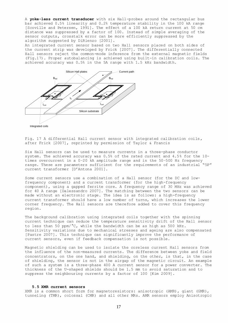
An integrated current sensor based on two Hall sensors placed on both sides of
the current strip was developed by Frick [2007]. The differentially connected
Hall sensors reject the common-mode inference from the external magnetic fields
(Fig.17). Proper autobalancing is achieved using built-in calibration coils. The
achieved accuracy was 0.5% in the 5A range with 1.5 kHz bandwidth.
Silicon substrate
Silicon Hall plates Current path
Bbal Bbal
IC
IcoilIcoil
Integrated coils
Fig. 17 A differential Hall current sensor with integrated calibration coils,
after Frick [2007], reprinted by permission of Taylor & Francis
Six Hall sensors can be used to measure currents in a three-phase conductor
system. The achieved accuracy was 0.5% of the rated current and 4.5% for the 10-
times overcurrent in a 0–20 kA amplitude range and in the 50–500 Hz frequency
range. These are parameters sufficient for the requirements of an industrial “5P”
current transformer [D’Antona 2001].
Some current sensors use a combination of a Hall sensor (for the DC and low-
frequency component) and a current transformer (for the high-frequency
component), using a gapped ferrite core. A frequency range of 30 MHz was achieved
for 40 A range [Dalessandro 2007]. The matching between the two sensors can be
made without an electronic stage. The idea is as follows: a high-frequency
current transformer should have a low number of turns, which increases the lower
corner frequency. The Hall sensors are therefore added to cover this frequency
region.
The background calibration using integrated coils together with the spinning
current technique can reduce the temperature sensitivity drift of the Hall sensor
to less than 50 ppm/°C, while the bandwidth can be as high as 500 kHz.
Sensitivity variations due to mechanical stresses and ageing are also compensated
[Pastre 2007]. This technique can significantly improve the performance of
current sensors, even if feedback compensation is not possible.
Magnetic shielding can be used to isolate the coreless current Hall sensors from
the influence of the non-measured currents. The difference between yoke and field
concentrators, on the one hand, and shielding, on the other, is that, in the case
of shielding, the sensor is not in the airgap of the magnetic circuit. An example
of such a system is a three-phase 400 A current sensor for a power converter. The
thickness of the U-shaped shields should be 1.5 mm to avoid saturation and to
suppress the neighbouring currents by a factor of 100 [Kim 2009].
5.5 XMR current sensors XMR is a common short form for magnetoresistors: anisotropic (AMR), giant (GMR),
tunneling (TMR), colossal (CMR) and all other MRs. AMR sensors employ Anisotropic
18
MagnetoResistance. They have higher resolution than Hall sensors, but their
sensing direction is in the chip plane, so they cannot be built into the narrow
airgap in the magnetic yoke. Yokes with a large airgap suffer from field leakage
sensitivity to external currents and magnetic fields. Thus most current sensors
based on AMR magnetoresistors are yokeless. The popular configuration is again a
bridge measuring the magnetic gradient from the current, since it is resistant
against homogeneous external magnetic fields (e.g. from distant currents). The
bridge also suppresses the temperature variation of the electric resistivity of
the magnetoresistive material (Fig. 18). This type of sensor usually has the
current conductor integrated with the sensors in a single device to ensure stable
geometry. The bridge has all the barber poles in the same direction, which means
it is made insensitive to a homogeneous external field, but sensitive to measured
current through the bus bar [Lemme and Friedrich, 2000]. The measured current can
be compensated by a feedback current through a compensation conductor. A typical
application is galvanically isolated current sensing in a PWM (pulse width
modulation) regulated brushless motor. These sensors are manufactured by Sensitec
(also under the F.W. Bell label) with ranges from 5 to 220 A. The achieved
linearity is 0.1%, temperature coefficient of sensitivity is 100 ppm/K, and the
offset drift in the (–45°C to +85°C) range is 1.4% FS [Sensitec].
Vout
Imeas
Fig. 18 AMR current sensor – after [Ripka 2004]
A similar sensor with a GMR detector (which employs Giant MagnetoResistance) has
been developed by Siemens [Vieth 2000] and later improved by Reig [2004], and
Pannetier-Lecouer [2007]. While the linearization of AMR sensors is achieved by
using barber poles, GMR sensor technology does not have such a “geometric trick”.
To make the GMR bridge sensitive to the magnetic fields created by an electric
current, various techniques can be used:
1. use sensors with two opposite response characteristics: in spin-valve GMRs
this can be done by using hard magnetic layers with two opposite directions.
Vieth [2000] used two separate sensor chips. It is also possible to manufacture
such a structure on a single chip using two-step deposition with reversed
direction of the magnetic field.
2. use a meander shape of the current path in order to reverse the field
direction for two of the magnetoresistors. An FEM (finite element) analysis of
such a sensor was made by Beltran [2007]. The advantage of this method is that
19
the complete bridge with four active GMR sensing elements can be made
simultaneously on a single chip, so that their properties are identical and the
temperature compensation is very effective Reig [2004]. A similar approach was
used by Pannetier-Lecouer [2007].
3. inactivate two of the magnetoresistors, e.g. by shielding
Fig 19 shows the spin-valve current sensor using a meander current path. The four
GMR strips R1-R4 appear as short horizontal lines. They are exactly the same,
with the pinned layer easy axis and free layer easy axis denoted by solid arrows.
The measured current flows from left-to-right below R1 and R3, and from right-to-
left below R2 and R4. Therefore the associated magnetic field is parallel to the
pinned layer easy axis of R2 and R4, and antiparallel to the pinned layer easy
axis of R1 and R3. Then the magnetic field forces the free layer magnetization
vector, initially perpendicular to the magnetic field, to rotate (see Fig.
19(a)). As a result, for a given current direction, R1 and R3 increase and R2 and
R4 decrease. Fig. 19(b) shows how the resulting Wheatstone bridge works.
20
Fig. 19 Sensor schemes: (a) detailed function principle (notice that due to the
scale the conductor traces are not discernible) ; (b) Wheatstone
bridge equivalent - from [Reig 2004], with permission from Elsevier.
In some of these sensors, additional biasing was achieved by permanent magnets in
order to increase the linearity and stabilize the sensors against large external
fields. Proper techniques such as feedback compensation should be used to
compensate for the temperature dependence of the biasing magnet.
GMR sensors may exhibit a large irreversible change of characteristic after a
magnetic shock created by a large external field or overcurrent.
Another possible configuration is a multi-sensor arrangement in a circular
pattern around the measured conductor. This can be used for any magnetic sensor –
pinned layer easy axis
free layer easy axis
electrical current
magnetic field
z
(a)
(b)
R1
R2
R3
R4
A
C
D
B
x
y
21
especially Hall sensors - to measure large currents, and for AMR sensors to
measure lower currents.
If we only make a summation of the sensor outputs, the error caused by displacing
the measured current from the center position depends strongly on the number of
sensors. Fig. 20 shows the simulated results: with 4 sensors the maximum
theoretical error is 3%, while for 8 sensors it is below 0.1%.
Fig. 20 The theoretical dependence of the relative error of the current
determination, when the wire rotates around the measurement hole for various
numbers of sensors. Diameter of the hole 10 mm, diameter of the sensor array
25.4mm (1 in.) – from [Mlejnek 2008], reproduced with permission from Elsevier
A linearity error of ±0.05% in the current range of ±8A was achieved using 8
Philips KMZ51 AMR sensors (Fig. 21). The error caused by an uncentered wire is
±0.5%, which is 5-times worse than predicted by the numerical simulation. This
degradation is caused by differences between the sensitivities of the individual
uncompensated sensors. An external current of 5A at a distance of 40mm from the
sensor array center causes an additional absolute error of max. 25 mA. [Mlejnek
2008].
Fig.21 a) The AMR current probe layout, b)the linearity error for a centered wire and a compensated sensor – from [Mlejnek 2008], reproduced with permission from Elsevier
(b)
(a)
22
5.6 Magnetooptical current sensors (including fibre-optic)
Optical current sensors have several advantages which are very attractive for
power distribution applications:
1. Effective isolation from high potentials
2. Immunity against electromagnetic interferences
3. High dynamic range, no saturation effects
4. High bandwidth
5. Compact and lightweight design.
These features offer a significant cost reduction in comparison to conventional
high-voltage current transformers.
Most optical current sensors are based on the Faraday Effect - either in bulk
material or in an optical fibre.
The polarization plane of a linearly polarized light which travels through the
magneto optical material is rotated by angle α, which is given as
C
dlBV
where V is the Verdet constant, B is the magnetic field strength
dl is the line element along the optical path inside the material.
Magneto optical current sensors are ideally suited for high-voltage high-current
applications [Cruden 1998].
Detection schemes
Most of these devices use either the interferometric principle or the
polarometric principle. The interferometric configurations utilize a Sagnac
interferometer, which we will discuss later in the section on intrinsic optical-
fibre sensors.
The basic polarometric detection scheme consists of a polarizer at the sensor’s
input to generate a linearly polarized optical state, and an analyser at the
output which converts the polarization change due to the Faraday Effect into an
intensity measurement. In common applications, the cross-polarization angle
between the two polarizers is set at 45°. However, a different angle may bring
higher immunity to the noise caused by the sensitivity of the interconnecting
optical fibres to mechanical vibrations [Fisher 1995]. It has been shown that the
major source of the noise is birefringence induced by the external vibrations
acting on the up-link fibre. Another noise-rejection scheme utilizes two downlink
optical fibre leads: one carries the signal before the analyzer (noise only),
while the other carries the signal after the analyzer (Faraday signal + noise).
Noise rejection is performed by subtracting the intensity signal from these two
downlink fibres [Fisher 1996a].
Some sensors use a dual-frequency or polychromatic light source and chromatic
sensing. This utilizes the wavelength dependency of the Verdet constant V. The
use of two or more photo detectors may effectively compensate for temperature
dependencies and other stray effects.
Bulk Magneto optical sensors
Magneto optical point sensors (or unlinked sensors) use a piece of glass or a
crystal rod placed in the neighbourhood of the electrical conductor. The sensor
is usually interrogated by optical fibres. These devices are robust, cheap, and
sensitive. They belong to the class of “extrinsic fibre sensors”, i.e. sensors
which use optical fibres for transmission, not for sensing. These sensors are
employed in the first generation of the ABB magneto-optic current transducer
(MOCT), which served for more than 15 years in industrial applications. The ABB
sensor achieves an accuracy class of 0.2 in the 3000 A range.
23
Using a bulk flint glass optical detector in the 20 mm wide airgap of a
ferromagnetic yoke, a noise level of 1.6 mA/√Hz@280 Hz was achieved. However such
a large airgap should significantly reduce the geometrical selectivity [Yi 2002].
Yoshino [2001] used a transverse configuration of the light beam and current-
induced magnetic field. This sensor requires only a 3 mm airgap so that the
surrounding currents are better suppressed. In any case, using a ferromagnetic
yoke brings the danger of saturation.
The triangular prism bulk magneto optical sensor has a closed sensing optical
path around the measured conductor. This provides independence of the sensor
output from the position of the measured conductor within the closed path, and
also resistance to external conductors and external homogeneous magnetic fields.
The sensor configuration is shown in Fig. 22. The noise rejection scheme using
two down links is also shown here [Fisher 1996b].
Fig. 22 Bulk-optic triangular Faraday current sensor. The position of the
internal (measured) conductor and external conductor is also shown - from [Fisher
1996a].
In order to increase the sensitivity, light can be passed several times around
the conductor using multiple reflections. A sensor with three 3-D loops using
total reflection at the glass surface is shown in [Ning 1995]. If total
reflection is used, the optical attenuation is low, but multiple reflections
cause elliptical polarization [Li 1999].
When measuring a very large current, the sensor information can be ambiguous, as
the phase shift may exceed 360°. This can be solved by counting how many times
the phase crossed 0°. This technique was used to measure 720 kA current pulses
using a 100 mm x 100 mm Schott glass (SF4) sensing element excited by a 532 nm,
100 mW solid-state laser [Deng 2008].
Broad-band light sources such as LEDs are often used in these devices. The
dominant source of dispersion is the wavelength dependence of the Verdet
constant. It was theoretically proven that that the error accumulation due to
spectral width variation is so small that it can be neglected, and a
monochromatic model can be used even for broadband optical current sensors [Wang
2005].
If bulk magneto optical sensors are used to measure the current in three-phase
systems, compensation should be made for the crosstalk from other conductors
[Perciante 2008].
Faraday mirrors can also be used to measure current: these sensors are also
called orthoconjugate reflector (OCR) current sensors. While the birefringence in
the glass current-sensing head causes the plane of polarization to rotate by
approximately 20°, Faraday mirror sensors exhibit only 5° birefringence [Wang
2007].
24
All-fibre sensors (or intrinsic fibre sensors)
In wound fibre devices, too, the magneto optical material encloses the electrical
conductor, and thus these sensors are not sensitive to external currents and
magnetic fields.
Optical fibre is made from materials that have much lower Verdet constants than
the magneto optic crystals used for bulk sensors, but their sensitivity can be
increased by using a higher number of turns of the fibre wound around the
measured conductor. Fibre-optic sensors are simple devices, they suffer from the
spurious birefringence induced in bent fibres [Perciante 2008].
Sensors with back light propagation can be constructed to compensate for
birefringence. This approach exploits the non-reciprocity of the Faraday Effect
and the reciprocity of linear birefringence. The light wave is reflected on the
far end and its polarization state is rotated by 90°. Then, it is coupled back
into the fibre [Drexler 2008]. A sensor of this type, made of low-birefringent flint fibre with a very low photo elastic constant, achieved the accuracy
required for the 0.1% class of current transformers in the range of 1 kA
[Kurosawa 2000].
All-fibre sensors can be made flexible using back-and-forth propagation through a
twisted sensing fibre [Alasia 2004]. Such sensors can be wound around the
measured conductor on existing installations.
A polarimetric current sensor utilizing a fibre-laser was reported in [Lee 1998].
The output of this sensor is a frequency, and it is immune to intensity
perturbations. 1 mA resolution for AC current was achieved for 1 turn of the
measuring fibre. Although the results are promising, this scheme has not been
applied in industry due to its complexity.
Sagnac interferometer-type fibre optic sensors have the big advantage that they
can use the technology originally developed for fibre-optic gyros [Takahashi
2004]. The early models used polarization maintaining (PM) fibres, which are
expensive and difficult to install. Even with the best PM fibres, polarization
phase noise was still a problem. Figure 23 shows the configuration, using a
depolarizer and a single-mode (SM) sensing fibre. The light source is a 0.85 μm
super-luminescent diode (SLD). The light passing through the sensing fibre coil
is circularly polarized by fibre polarizers and 1/4-wavelength plates at both
ends of the sensor fibre. The detection scheme utilized a PZT piezoelectric
modulator and complicated demodulation. The rated current of the sensor designed
by Takahashi [2004] is 3000 A, and the maximum measured current is 100 kA. Such a
large dynamic range allows the use of the same device for measurement and
protection purposes. The birefringence of the sensing fibre was suppressed using
a twisted double-coated low birefringence fibre. The sensor linearity was better
than 0.2%. Figs. 24 and 25 show the ratio and phase errors as a function of the
measured current. The achieved errors are very small, and they do not
significantly increase at low currents. In the temperature range of -40 to +60°C,
the maximum ratio error was ± 0.2% (Fig. 26). All these characteristics apply to
AC 50 Hz or 60 Hz currents. When measuring DC currents, this sensor suffers from
10 A/h drift caused by 0.05 mrad non-reciprocal phase shift. The temperature
dependence of the Verdet constant of the sensing fibre (0.69 × 10⁻⁴ K−1) is
compensated.
25
Fig. 23 Schematic diagram of the fibre-optic current sensor -from [Takahashi
2004].
Fig. 24 Ratio error characteristics of the fibre-optic current sensor - from
[Takahashi 2004].
Fig. 25 Phase displacement characteristics of the fibre-optic current sensor -
from [Takahashi 2004].
Primary current (ARMS)
Primary current (ARMS)
26
Fig. 26 Temperature characteristics of the fibre-optic current
sensor - from [Takahashi 2004].
A commercially available all-fibre current sensor was manufactured by ABB [2005].
This device also uses two circularly polarized light waves, but travelling in the
same direction. Two linearly polarized light waves with orthogonal polarization
are passed through the optical fibre. At the point where the sensitive region
starts, the waves are converted by the phase retarder into left and right
circularly polarized light waves. The magnetic field caused by the measured
current causes a nonreciprocal phase shift between the two beams by the Faraday
Effect. Both waves are reflected at the end of the fibre with swapped
polarization, and return back to the optical module. On leaving the measuring
coil, the circular waves are converted back to linearly polarized light. This
configuration effectively suppresses the bending-induced linear birefringence in
the fibre, which can be in the order of 5° – 10° per coil turn, with the
orientation within the coil plane [Zhou 2007]. The phase difference caused by the
magnetic field is then measured by the interferometer. The measuring range is 600
kA, corresponding to 360 deg. phase difference, while the resolution is 0.25 A.
The sensitivity can certainly be increased by using multiple turns of the optical
fibre around the measured conductor. Great care was taken to insulate the
measuring fibre from mechanical stress and vibrations, as this is a major
source of temperature sensitivity drift. The sensing fibre is thermally annealed
to remove residual stresses and covered by a glass capillary, which is
embedded in a soft polymer ring.
The temperature dependence of the Faraday Effect (0.7x10⁻⁴/°C) is partly
compensated by the temperature dependence of the retarder.
Similar sensors were developed for measuring large DC currents: the achieved
accuracy is 0.1% for currents up to 600 kA [Bohnert 2007].
Fibre optic current sensors allow multiplexing of other signals using the same
fibre. A system combining a polarometric current sensor based on the Faraday
Effect with a voltage sensor based on the Pockels effect is described in [Ferrari
2009]. The Faraday sensor works in the violet region, where the Verdet constant
is large, while the Pockels cell works in the green region. A third beam, which
is blue, serves as a reference. This approach is limited by the low accuracy of
the Pockels cell and by the non-ideal characteristics of the filters.
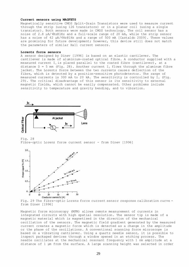
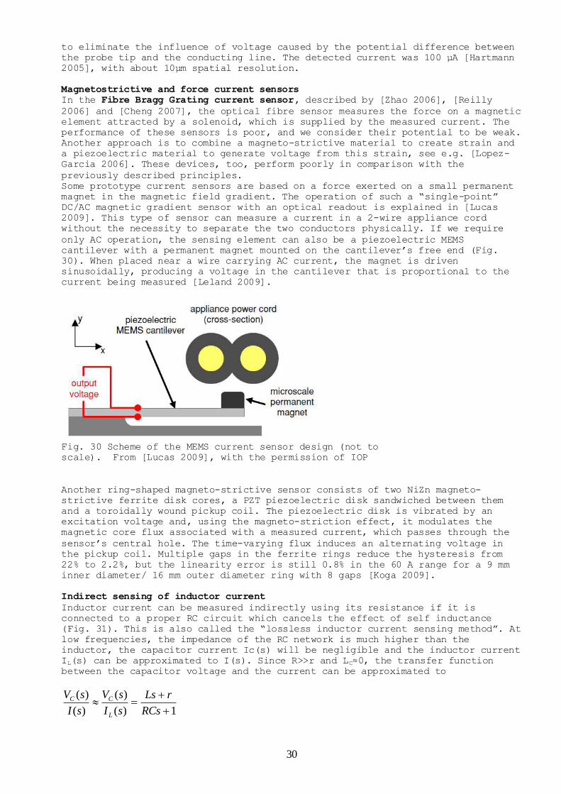
Other types of extrinsic fibre optic current sensors
These sensors utilize optical fibres for connection to a separate sensing
element. The first class of these sensors comprises bulk magneto optical sensors
(Section 4.8.1). Other current sensors can also be used; the required electric
supply energy can be converted from the incoming light. However, using active
components at high potential is dangerous, as they can easily be destroyed in a
strong electric field during voltage transients. Completely passive sensors can
be built using the secondary current of the instrument current transformer to
directly excite the light-emitting diode (LED], which sends light through the
downlink optical fibre. Using the wavelength shift of green ultra-bright LEDs
instead of intensity modulation can overcome some of the problems with drifts and
27
noise, but the LED temperature stability is still a problem [Ribeiro 2008]. A
current clamp transformer was used to directly excite the piezoelectric PZT
element attached to Fibre Bragg grating (FBG) [Fisher 1997]. The measured DC or
AC current is converted to the strain of the FBG, resulting in a wavelength
shift. The FBG is illuminated by a remote broadband source, and the resonance
frequencies of all 3 FBGs working at different frequencies are measured using an