RENEWAIRE ERV + ELECTRIC DUCT HEATER: A SINGLE-SOURCE SOLUTION HEATER ELECTRIC DUCT EVERY GEOGRAPHY, EVERY CLIMATE, EVERY HOME, EVERY BUILDING AND EVERY APPLICATION RENEWAIRE EVERYWHERE FLIPPABLE EK SERIES SHOWN RH SERIES RH-W SHOWN
Transcript
RENEWAIRE ERV + ELECTRIC DUCT HEATER: A S INGLE-SOURCE SOLUT ION
HEATERELECTRIC DUCT
E V E R Y G E O G R A P H Y , E V E R Y C L I M A T E , E V E R Y H O M E ,
E V E R Y B U I L D I N G A N D E V E R Y A P P L I C A T I O N
REMOTE DUCT TEMPERATURE SENSOR (DS-600)The sensor lowers the controllable output temperature range to -3–130˚ F from 50–130˚ F obtained using the internal sensor, provided standard in RH-W heater thermostats. The lower temperature range is commonly used for pre-heat applications. This remote sensor can also be used in RH-D heaters to control the output temperature at some distance from the RH-D heater.
DIGITAL TIME CLOCK (TC7D-W OR TC7D-E)The time clock can be used to lower the set-point temperature by 8˚ F at scheduled times with a RH-W heater thermostat.
MOTION OCCUPANCY SENSOR/CONTROL (MC-C OR MC-W)The motion sensor can be used to lower the set-point temperature by 8˚ F when unoccupied with a RH-W heater thermostat.
EK
SE
RIE
S
RH
SE
RIE
S
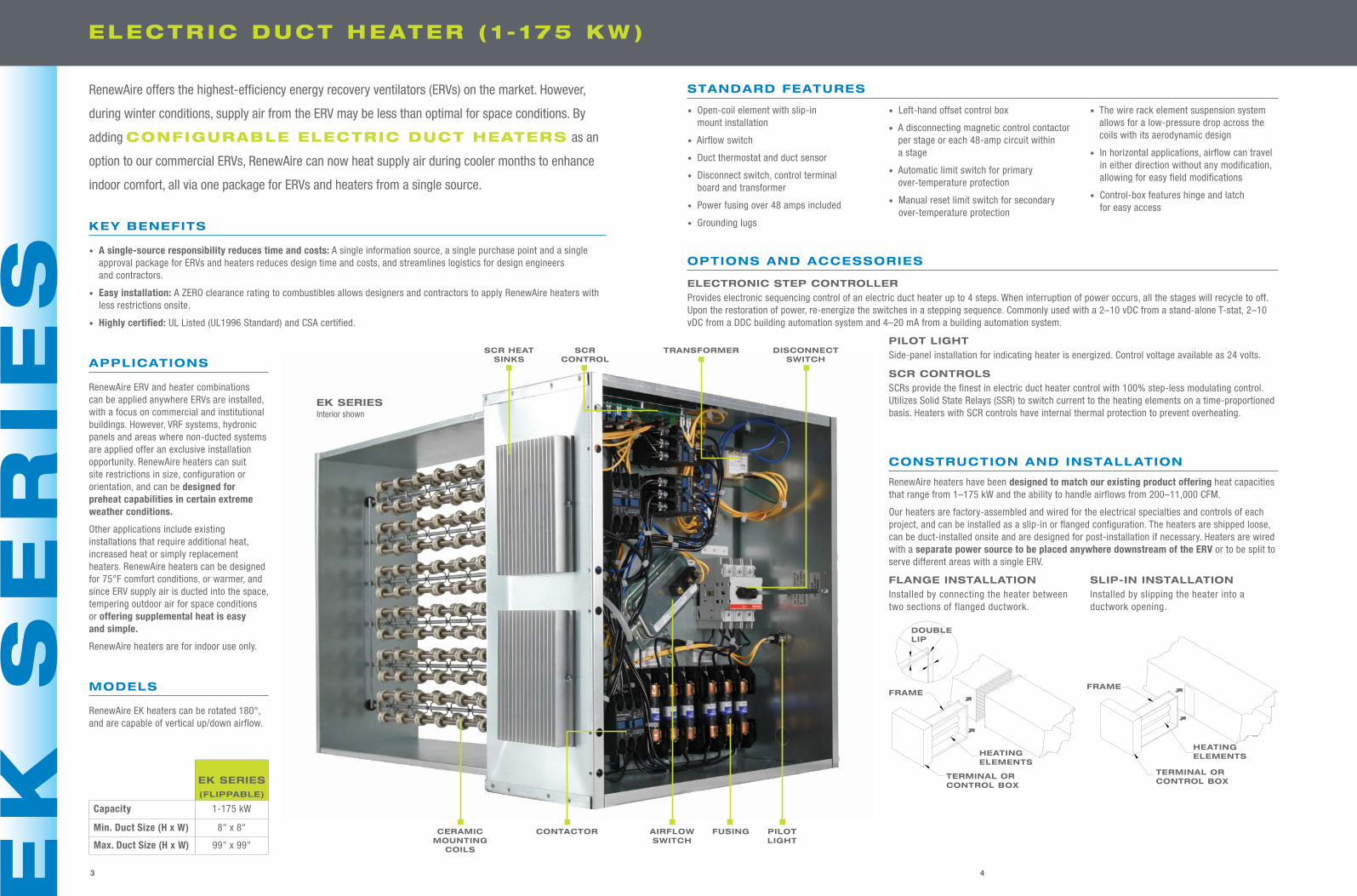
EK SERIES (FLIPPABLE)
Capacity 1-175 kW
Min. Duct Size (H x W) 8" x 8"
Max. Duct Size (H x W) 99" x 99"
STANDARD FEATURES
u Open-coil element with slip-in mount installation
u Airflow switch
u Duct thermostat and duct sensor
u Disconnect switch, control terminal board and transformer
u Power fusing over 48 amps included
u Grounding lugs
u Left-hand offset control box
u A disconnecting magnetic control contactor per stage or each 48-amp circuit within a stage
u Automatic limit switch for primary over-temperature protection
u Manual reset limit switch for secondary over-temperature protection
u The wire rack element suspension system allows for a low-pressure drop across the coils with its aerodynamic design
u In horizontal applications, airflow can travel in either direction without any modification, allowing for easy field modifications
u Control-box features hinge and latch for easy access
RenewAire offers the highest-efficiency energy recovery ventilators (ERVs) on the market. However,
during winter conditions, supply air from the ERV may be less than optimal for space conditions. By
adding CONFIGURABLE ELECTRIC DUCT HEATERS as an
option to our commercial ERVs, RenewAire can now heat supply air during cooler months to enhance
indoor comfort, all via one package for ERVs and heaters from a single source.
43 65
ELECTR IC DUCT HEATER ( 1 - 175 KW) ELECTR IC DUCT HEATER ( 1 - 1 1 .5 KW)
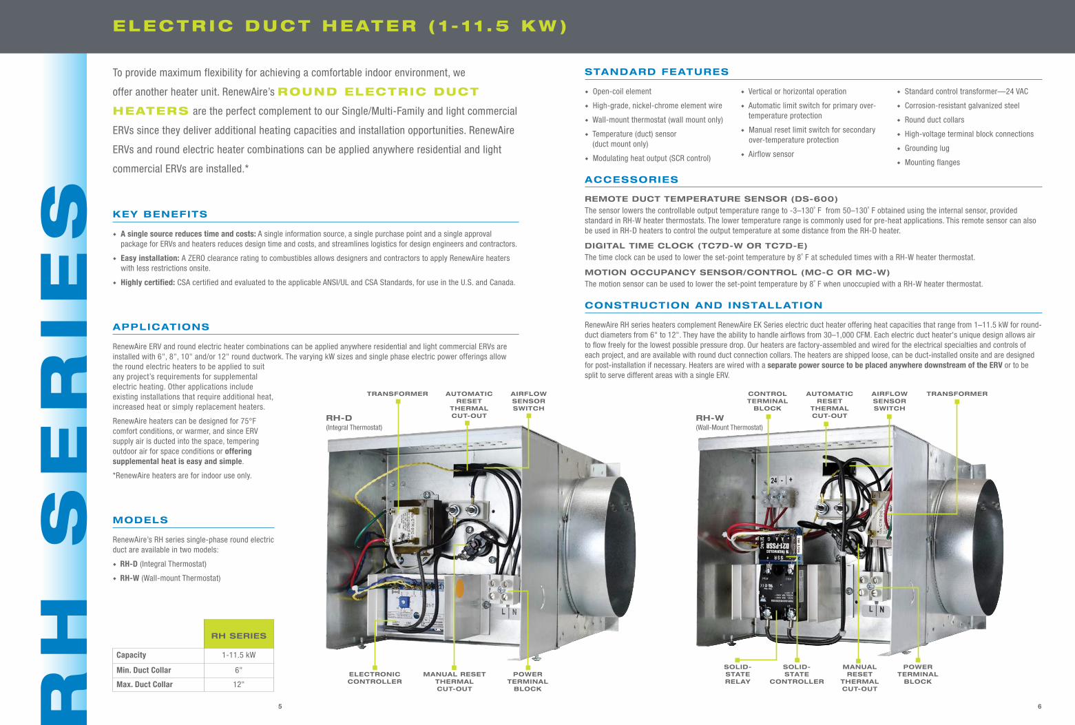
RH SERIES
Capacity 1-11.5 kW
Min. Duct Collar 6"
Max. Duct Collar 12"
STANDARD FEATURES
u Open-coil element
u High-grade, nickel-chrome element wire
u Wall-mount thermostat (wall mount only)
u Temperature (duct) sensor (duct mount only)
u Modulating heat output (SCR control)
u Vertical or horizontal operation
u Automatic limit switch for primary over-temperature protection
u Manual reset limit switch for secondary over-temperature protection
u Airflow sensor
u Standard control transformer—24 VAC
u Corrosion-resistant galvanized steel
u Round duct collars
u High-voltage terminal block connections
u Grounding lug
u Mounting flanges
RenewAire RH series heaters complement RenewAire EK Series electric duct heater offering heat capacities that range from 1–11.5 kW for round-duct diameters from 6" to 12". They have the ability to handle airflows from 30–1,000 CFM. Each electric duct heater's unique design allows air to flow freely for the lowest possible pressure drop. Our heaters are factory-assembled and wired for the electrical specialties and controls of each project, and are available with round duct connection collars. The heaters are shipped loose, can be duct-installed onsite and are designed for post-installation if necessary. Heaters are wired with a separate power source to be placed anywhere downstream of the ERV or to be split to serve different areas with a single ERV.
CONSTRUCTION AND INSTALLATION
KEY BENEFITS
u A single source reduces time and costs: A single information source, a single purchase point and a single approval package for ERVs and heaters reduces design time and costs, and streamlines logistics for design engineers and contractors.
u Easy installation: A ZERO clearance rating to combustibles allows designers and contractors to apply RenewAire heaters with less restrictions onsite.
u Highly certified: CSA certified and evaluated to the applicable ANSI/UL and CSA Standards, for use in the U.S. and Canada.
RenewAire ERV and round electric heater combinations can be applied anywhere residential and light commercial ERVs are installed with 6", 8", 10" and/or 12" round ductwork. The varying kW sizes and single phase electric power offerings allow
APPLICATIONS
the round electric heaters to be applied to suit any project’s requirements for supplemental electric heating. Other applications include existing installations that require additional heat, increased heat or simply replacement heaters.
RenewAire heaters can be designed for 75°F comfort conditions, or warmer, and since ERV supply air is ducted into the space, tempering outdoor air for space conditions or offering supplemental heat is easy and simple.
*RenewAire heaters are for indoor use only.
MODELS
RenewAire’s RH series single-phase round electric duct are available in two models:
u RH-D (Integral Thermostat)
u RH-W (Wall-mount Thermostat)
KEY BENEFITS
u A single-source responsibility reduces time and costs: A single information source, a single purchase point and a single approval package for ERVs and heaters reduces design time and costs, and streamlines logistics for design engineers and contractors.
u Easy installation: A ZERO clearance rating to combustibles allows designers and contractors to apply RenewAire heaters with less restrictions onsite.
u Highly certified: UL Listed (UL1996 Standard) and CSA certified.
APPLICATIONS
RenewAire ERV and heater combinations can be applied anywhere ERVs are installed, with a focus on commercial and institutional buildings. However, VRF systems, hydronic panels and areas where non-ducted systems are applied offer an exclusive installation opportunity. RenewAire heaters can suit site restrictions in size, configuration or orientation, and can be designed for preheat capabilities in certain extreme weather conditions.
Other applications include existing installations that require additional heat, increased heat or simply replacement heaters. RenewAire heaters can be designed for 75°F comfort conditions, or warmer, and since ERV supply air is ducted into the space, tempering outdoor air for space conditions or offering supplemental heat is easy and simple.
RenewAire heaters are for indoor use only.
MODELS
RenewAire EK heaters can be rotated 180°, and are capable of vertical up/down airflow.
OPTIONS AND ACCESSORIES
ELECTRONIC STEP CONTROLLERProvides electronic sequencing control of an electric duct heater up to 4 steps. When interruption of power occurs, all the stages will recycle to off. Upon the restoration of power, re-energize the switches in a stepping sequence. Commonly used with a 2–10 vDC from a stand-alone T-stat, 2–10 vDC from a DDC building automation system and 4–20 mA from a building automation system.
PILOT LIGHTSide-panel installation for indicating heater is energized. Control voltage available as 24 volts.
SCR CONTROLSSCRs provide the finest in electric duct heater control with 100% step-less modulating control. Utilizes Solid State Relays (SSR) to switch current to the heating elements on a time-proportioned basis. Heaters with SCR controls have internal thermal protection to prevent overheating.
CONSTRUCTION AND INSTALLATION
RenewAire heaters have been designed to match our existing product offering heat capacities that range from 1–175 kW and the ability to handle airflows from 200–11,000 CFM.
Our heaters are factory-assembled and wired for the electrical specialties and controls of each project, and can be installed as a slip-in or flanged configuration. The heaters are shipped loose, can be duct-installed onsite and are designed for post-installation if necessary. Heaters are wired with a separate power source to be placed anywhere downstream of the ERV or to be split to serve different areas with a single ERV.
SLIP-IN INSTALLATIONInstalled by slipping the heater into a ductwork opening.
06-4141-00 REV. C E.C.O. 10438
INSTALLATION MANUAL
TUTCO DUCT HEATERSThe information and instructions in this sheet apply to Duct Heatermodels for zero clearance installation in ducts.
The Duct Heaters are approved for use with heat pumps, airconditioners, or other forced air systems. They may be controlled bycontactors, relays, sequencers or solid state devices.
The Duct Heaters are prewired, have voltage ratings to 600 volts, bothsingle phase and three phase.
The Duct Heaters are furnished with integral controls, except for the DD& DHD series, which are furnished with a separate control panel forremote mounting.
GENERAL:Inspect heater for any possible shipping damage. Check all insulatorsfor breakage and inspect heater element wire for any deformation thatcould cause a short circuit or ground. Make sure all fasteners are tight.Electrical connections such as pressure terminals should be checked fortightness.
INSTALLATION:For safe operation and best performance, the following installationprocedures must be adhered to.
Heaters may be installed in the sides of either horizontal or verticalducts but never in the top or bottom of a horizontal duct. Heatersinstalled in vertical ducts are tested and approved for up airflow only!
1.Install a heater a minimum of (4) feet from heat pumps or central airconditioners.
2. At least 4 feet downstream from an air handler.
3. At least 2 feet either side of an elbow or turn.
4. At least 4 feet from any canvas duct connector or transition section forchange in duct size.
5. At least 4 feet downstream from an air filter.
6. At least 4 feet upstream from a humidifier.
Refer to the back of this sheet for: duct, electrical and air velocityrequirements.
To install a slip-in heater FIG.1, cut an opening, as required in the sideof the duct. Slide heater in the duct using control box as template tomark the mounting screw holes. Remove unit and drill mounting holes.Mount unit to duct with sheet metal screws. Connect high and lowvoltage supplies along with fan interlock circuit (if no airflow switch isfurnished). Larger heaters may require hangers.
To install a flange type heater FIG.2, Insert heater between two sectionsof flanged duct and bolt in place. For additional strength, the duct flangeshould be doubled as shown in the figure. Large heaters may requirehanger straps. Connect high and low voltage supplies along with faninterlock circuit (if no airflow switch is furnished).
FLANGE INSTALLATIONInstalled by connecting the heater between two sections of flanged ductwork.
06-4141-00 REV. C E.C.O. 10438
INSTALLATION MANUAL
TUTCO DUCT HEATERSThe information and instructions in this sheet apply to Duct Heatermodels for zero clearance installation in ducts.
The Duct Heaters are approved for use with heat pumps, airconditioners, or other forced air systems. They may be controlled bycontactors, relays, sequencers or solid state devices.
The Duct Heaters are prewired, have voltage ratings to 600 volts, bothsingle phase and three phase.
The Duct Heaters are furnished with integral controls, except for the DD& DHD series, which are furnished with a separate control panel forremote mounting.
GENERAL:Inspect heater for any possible shipping damage. Check all insulatorsfor breakage and inspect heater element wire for any deformation thatcould cause a short circuit or ground. Make sure all fasteners are tight.Electrical connections such as pressure terminals should be checked fortightness.
INSTALLATION:For safe operation and best performance, the following installationprocedures must be adhered to.
Heaters may be installed in the sides of either horizontal or verticalducts but never in the top or bottom of a horizontal duct. Heatersinstalled in vertical ducts are tested and approved for up airflow only!
1.Install a heater a minimum of (4) feet from heat pumps or central airconditioners.
2. At least 4 feet downstream from an air handler.
3. At least 2 feet either side of an elbow or turn.
4. At least 4 feet from any canvas duct connector or transition section forchange in duct size.
5. At least 4 feet downstream from an air filter.
6. At least 4 feet upstream from a humidifier.
Refer to the back of this sheet for: duct, electrical and air velocityrequirements.
To install a slip-in heater FIG.1, cut an opening, as required in the sideof the duct. Slide heater in the duct using control box as template tomark the mounting screw holes. Remove unit and drill mounting holes.Mount unit to duct with sheet metal screws. Connect high and lowvoltage supplies along with fan interlock circuit (if no airflow switch isfurnished). Larger heaters may require hangers.
To install a flange type heater FIG.2, Insert heater between two sectionsof flanged duct and bolt in place. For additional strength, the duct flangeshould be doubled as shown in the figure. Large heaters may requirehanger straps. Connect high and low voltage supplies along with faninterlock circuit (if no airflow switch is furnished).
To provide maximum flexibility for achieving a comfortable indoor environment, we
offer another heater unit. RenewAire’s ROUND ELECTRIC DUCT
HEATERS are the perfect complement to our Single/Multi-Family and light commercial
ERVs since they deliver additional heating capacities and installation opportunities. RenewAire
ERVs and round electric heater combinations can be applied anywhere residential and light
commercial ERVs are installed.*
ACCESSORIES
REMOTE DUCT TEMPERATURE SENSOR (DS-600)The sensor lowers the controllable output temperature range to -3–130˚ F from 50–130˚ F obtained using the internal sensor, provided standard in RH-W heater thermostats. The lower temperature range is commonly used for pre-heat applications. This remote sensor can also be used in RH-D heaters to control the output temperature at some distance from the RH-D heater.
DIGITAL TIME CLOCK (TC7D-W OR TC7D-E)The time clock can be used to lower the set-point temperature by 8˚ F at scheduled times with a RH-W heater thermostat.
MOTION OCCUPANCY SENSOR/CONTROL (MC-C OR MC-W)The motion sensor can be used to lower the set-point temperature by 8˚ F when unoccupied with a RH-W heater thermostat.
EK
SE
RIE
S
RH
SE
RIE
S
EK SERIES (FLIPPABLE)
Capacity 1-175 kW
Min. Duct Size (H x W) 8" x 8"
Max. Duct Size (H x W) 99" x 99"
STANDARD FEATURES
u Open-coil element with slip-in mount installation
u Airflow switch
u Duct thermostat and duct sensor
u Disconnect switch, control terminal board and transformer
u Power fusing over 48 amps included
u Grounding lugs
u Left-hand offset control box
u A disconnecting magnetic control contactor per stage or each 48-amp circuit within a stage
u Automatic limit switch for primary over-temperature protection
u Manual reset limit switch for secondary over-temperature protection
u The wire rack element suspension system allows for a low-pressure drop across the coils with its aerodynamic design
u In horizontal applications, airflow can travel in either direction without any modification, allowing for easy field modifications
u Control-box features hinge and latch for easy access
RenewAire offers the highest-efficiency energy recovery ventilators (ERVs) on the market. However,
during winter conditions, supply air from the ERV may be less than optimal for space conditions. By
adding CONFIGURABLE ELECTRIC DUCT HEATERS as an
option to our commercial ERVs, RenewAire can now heat supply air during cooler months to enhance
indoor comfort, all via one package for ERVs and heaters from a single source.
43 65
ELECTR IC DUCT HEATER ( 1 - 175 KW) ELECTR IC DUCT HEATER ( 1 - 1 1 .5 KW)
RH SERIES
Capacity 1-11.5 kW
Min. Duct Collar 6"
Max. Duct Collar 12"
STANDARD FEATURES
u Open-coil element
u High-grade, nickel-chrome element wire
u Wall-mount thermostat (wall mount only)
u Temperature (duct) sensor (duct mount only)
u Modulating heat output (SCR control)
u Vertical or horizontal operation
u Automatic limit switch for primary over-temperature protection
u Manual reset limit switch for secondary over-temperature protection
u Airflow sensor
u Standard control transformer—24 VAC
u Corrosion-resistant galvanized steel
u Round duct collars
u High-voltage terminal block connections
u Grounding lug
u Mounting flanges
RenewAire RH series heaters complement RenewAire EK Series electric duct heater offering heat capacities that range from 1–11.5 kW for round-duct diameters from 6" to 12". They have the ability to handle airflows from 30–1,000 CFM. Each electric duct heater's unique design allows air to flow freely for the lowest possible pressure drop. Our heaters are factory-assembled and wired for the electrical specialties and controls of each project, and are available with round duct connection collars. The heaters are shipped loose, can be duct-installed onsite and are designed for post-installation if necessary. Heaters are wired with a separate power source to be placed anywhere downstream of the ERV or to be split to serve different areas with a single ERV.
CONSTRUCTION AND INSTALLATION
KEY BENEFITS
u A single source reduces time and costs: A single information source, a single purchase point and a single approval package for ERVs and heaters reduces design time and costs, and streamlines logistics for design engineers and contractors.
u Easy installation: A ZERO clearance rating to combustibles allows designers and contractors to apply RenewAire heaters with less restrictions onsite.
u Highly certified: CSA certified and evaluated to the applicable ANSI/UL and CSA Standards, for use in the U.S. and Canada.
RenewAire ERV and round electric heater combinations can be applied anywhere residential and light commercial ERVs are installed with 6", 8", 10" and/or 12" round ductwork. The varying kW sizes and single phase electric power offerings allow
APPLICATIONS
the round electric heaters to be applied to suit any project’s requirements for supplemental electric heating. Other applications include existing installations that require additional heat, increased heat or simply replacement heaters.
RenewAire heaters can be designed for 75°F comfort conditions, or warmer, and since ERV supply air is ducted into the space, tempering outdoor air for space conditions or offering supplemental heat is easy and simple.
*RenewAire heaters are for indoor use only.
MODELS
RenewAire’s RH series single-phase round electric duct are available in two models:
u RH-D (Integral Thermostat)
u RH-W (Wall-mount Thermostat)
KEY BENEFITS
u A single-source responsibility reduces time and costs: A single information source, a single purchase point and a single approval package for ERVs and heaters reduces design time and costs, and streamlines logistics for design engineers and contractors.
u Easy installation: A ZERO clearance rating to combustibles allows designers and contractors to apply RenewAire heaters with less restrictions onsite.
u Highly certified: UL Listed (UL1996 Standard) and CSA certified.
APPLICATIONS
RenewAire ERV and heater combinations can be applied anywhere ERVs are installed, with a focus on commercial and institutional buildings. However, VRF systems, hydronic panels and areas where non-ducted systems are applied offer an exclusive installation opportunity. RenewAire heaters can suit site restrictions in size, configuration or orientation, and can be designed for preheat capabilities in certain extreme weather conditions.
Other applications include existing installations that require additional heat, increased heat or simply replacement heaters. RenewAire heaters can be designed for 75°F comfort conditions, or warmer, and since ERV supply air is ducted into the space, tempering outdoor air for space conditions or offering supplemental heat is easy and simple.
RenewAire heaters are for indoor use only.
MODELS
RenewAire EK heaters can be rotated 180°, and are capable of vertical up/down airflow.
OPTIONS AND ACCESSORIES
ELECTRONIC STEP CONTROLLERProvides electronic sequencing control of an electric duct heater up to 4 steps. When interruption of power occurs, all the stages will recycle to off. Upon the restoration of power, re-energize the switches in a stepping sequence. Commonly used with a 2–10 vDC from a stand-alone T-stat, 2–10 vDC from a DDC building automation system and 4–20 mA from a building automation system.
PILOT LIGHTSide-panel installation for indicating heater is energized. Control voltage available as 24 volts.
SCR CONTROLSSCRs provide the finest in electric duct heater control with 100% step-less modulating control. Utilizes Solid State Relays (SSR) to switch current to the heating elements on a time-proportioned basis. Heaters with SCR controls have internal thermal protection to prevent overheating.
CONSTRUCTION AND INSTALLATION
RenewAire heaters have been designed to match our existing product offering heat capacities that range from 1–175 kW and the ability to handle airflows from 200–11,000 CFM.
Our heaters are factory-assembled and wired for the electrical specialties and controls of each project, and can be installed as a slip-in or flanged configuration. The heaters are shipped loose, can be duct-installed onsite and are designed for post-installation if necessary. Heaters are wired with a separate power source to be placed anywhere downstream of the ERV or to be split to serve different areas with a single ERV.
SLIP-IN INSTALLATIONInstalled by slipping the heater into a ductwork opening.
06-4141-00 REV. C E.C.O. 10438
INSTALLATION MANUAL
TUTCO DUCT HEATERSThe information and instructions in this sheet apply to Duct Heatermodels for zero clearance installation in ducts.
The Duct Heaters are approved for use with heat pumps, airconditioners, or other forced air systems. They may be controlled bycontactors, relays, sequencers or solid state devices.
The Duct Heaters are prewired, have voltage ratings to 600 volts, bothsingle phase and three phase.
The Duct Heaters are furnished with integral controls, except for the DD& DHD series, which are furnished with a separate control panel forremote mounting.
GENERAL:Inspect heater for any possible shipping damage. Check all insulatorsfor breakage and inspect heater element wire for any deformation thatcould cause a short circuit or ground. Make sure all fasteners are tight.Electrical connections such as pressure terminals should be checked fortightness.
INSTALLATION:For safe operation and best performance, the following installationprocedures must be adhered to.
Heaters may be installed in the sides of either horizontal or verticalducts but never in the top or bottom of a horizontal duct. Heatersinstalled in vertical ducts are tested and approved for up airflow only!
1.Install a heater a minimum of (4) feet from heat pumps or central airconditioners.
2. At least 4 feet downstream from an air handler.
3. At least 2 feet either side of an elbow or turn.
4. At least 4 feet from any canvas duct connector or transition section forchange in duct size.
5. At least 4 feet downstream from an air filter.
6. At least 4 feet upstream from a humidifier.
Refer to the back of this sheet for: duct, electrical and air velocityrequirements.
To install a slip-in heater FIG.1, cut an opening, as required in the sideof the duct. Slide heater in the duct using control box as template tomark the mounting screw holes. Remove unit and drill mounting holes.Mount unit to duct with sheet metal screws. Connect high and lowvoltage supplies along with fan interlock circuit (if no airflow switch isfurnished). Larger heaters may require hangers.
To install a flange type heater FIG.2, Insert heater between two sectionsof flanged duct and bolt in place. For additional strength, the duct flangeshould be doubled as shown in the figure. Large heaters may requirehanger straps. Connect high and low voltage supplies along with faninterlock circuit (if no airflow switch is furnished).
FLANGE INSTALLATIONInstalled by connecting the heater between two sections of flanged ductwork.
06-4141-00 REV. C E.C.O. 10438
INSTALLATION MANUAL
TUTCO DUCT HEATERSThe information and instructions in this sheet apply to Duct Heatermodels for zero clearance installation in ducts.
The Duct Heaters are approved for use with heat pumps, airconditioners, or other forced air systems. They may be controlled bycontactors, relays, sequencers or solid state devices.
The Duct Heaters are prewired, have voltage ratings to 600 volts, bothsingle phase and three phase.
The Duct Heaters are furnished with integral controls, except for the DD& DHD series, which are furnished with a separate control panel forremote mounting.
GENERAL:Inspect heater for any possible shipping damage. Check all insulatorsfor breakage and inspect heater element wire for any deformation thatcould cause a short circuit or ground. Make sure all fasteners are tight.Electrical connections such as pressure terminals should be checked fortightness.
INSTALLATION:For safe operation and best performance, the following installationprocedures must be adhered to.
Heaters may be installed in the sides of either horizontal or verticalducts but never in the top or bottom of a horizontal duct. Heatersinstalled in vertical ducts are tested and approved for up airflow only!
1.Install a heater a minimum of (4) feet from heat pumps or central airconditioners.
2. At least 4 feet downstream from an air handler.
3. At least 2 feet either side of an elbow or turn.
4. At least 4 feet from any canvas duct connector or transition section forchange in duct size.
5. At least 4 feet downstream from an air filter.
6. At least 4 feet upstream from a humidifier.
Refer to the back of this sheet for: duct, electrical and air velocityrequirements.
To install a slip-in heater FIG.1, cut an opening, as required in the sideof the duct. Slide heater in the duct using control box as template tomark the mounting screw holes. Remove unit and drill mounting holes.Mount unit to duct with sheet metal screws. Connect high and lowvoltage supplies along with fan interlock circuit (if no airflow switch isfurnished). Larger heaters may require hangers.
To install a flange type heater FIG.2, Insert heater between two sectionsof flanged duct and bolt in place. For additional strength, the duct flangeshould be doubled as shown in the figure. Large heaters may requirehanger straps. Connect high and low voltage supplies along with faninterlock circuit (if no airflow switch is furnished).
TUTCO DUCT HEATERSThe information and instructions in this sheet apply to Duct Heatermodels for zero clearance installation in ducts.
The Duct Heaters are approved for use with heat pumps, airconditioners, or other forced air systems. They may be controlled bycontactors, relays, sequencers or solid state devices.
The Duct Heaters are prewired, have voltage ratings to 600 volts, bothsingle phase and three phase.
The Duct Heaters are furnished with integral controls, except for the DD& DHD series, which are furnished with a separate control panel forremote mounting.
GENERAL:Inspect heater for any possible shipping damage. Check all insulatorsfor breakage and inspect heater element wire for any deformation thatcould cause a short circuit or ground. Make sure all fasteners are tight.Electrical connections such as pressure terminals should be checked fortightness.
INSTALLATION:For safe operation and best performance, the following installationprocedures must be adhered to.
Heaters may be installed in the sides of either horizontal or verticalducts but never in the top or bottom of a horizontal duct. Heatersinstalled in vertical ducts are tested and approved for up airflow only!
1.Install a heater a minimum of (4) feet from heat pumps or central airconditioners.
2. At least 4 feet downstream from an air handler.
3. At least 2 feet either side of an elbow or turn.
4. At least 4 feet from any canvas duct connector or transition section forchange in duct size.
5. At least 4 feet downstream from an air filter.
6. At least 4 feet upstream from a humidifier.
Refer to the back of this sheet for: duct, electrical and air velocityrequirements.
To install a slip-in heater FIG.1, cut an opening, as required in the sideof the duct. Slide heater in the duct using control box as template tomark the mounting screw holes. Remove unit and drill mounting holes.Mount unit to duct with sheet metal screws. Connect high and lowvoltage supplies along with fan interlock circuit (if no airflow switch isfurnished). Larger heaters may require hangers.
To install a flange type heater FIG.2, Insert heater between two sectionsof flanged duct and bolt in place. For additional strength, the duct flangeshould be doubled as shown in the figure. Large heaters may requirehanger straps. Connect high and low voltage supplies along with faninterlock circuit (if no airflow switch is furnished).
To provide maximum flexibility for achieving a comfortable indoor environment, we
offer another heater unit. RenewAire’s ROUND ELECTRIC DUCT
HEATERS are the perfect complement to our Single/Multi-Family and light commercial
ERVs since they deliver additional heating capacities and installation opportunities. RenewAire
ERVs and round electric heater combinations can be applied anywhere residential and light
commercial ERVs are installed.*
7
RENEWAIRE.COM 1.800.627.4499 133132 FOR THE MOST COMPLETE AND CURRENT INFORMATION VISIT RENEWAIRE.COM
OPTIONS & ACCESSORIES
Specifi cations may be subject to change without notice.
FLIPPABLE EK SERIES
SHOWN
RenewAire offers the highest-efficiency energy recovery ventilators (ERVs) on the market. However, during
winter conditions, supply air from the ERV may be less than optimal for space conditions. By adding
CONFIGURABLE ELECTRIC DUCT HEATERS as an accessory to our
commercial ERVs, RenewAire can now heat supply air during cooler months to enhance indoor comfort,
all via one package for ERVs and heaters from a single source.
KEY BENEFITS
A single source reduces time and costs: A single information source, a single purchase point and a single approval package for ERVs and heaters reduces design time and costs, and streamlines logistics for design engineers and contractors.
More flexibility: RenewAire offers design engineers the capacity to specify ERVs with a matching heater to boost flexibility and provide heated air to a single space or multiple spaces.
Easy installation: A ZERO clearance rating to combustibles allows designers and contractors to apply RenewAire heaters with less restrictions onsite.
Ultimate reliability: RenewAire heaters come with our two-year warranty and unmatched reliability. Single-source responsibility offers contractors and end users peace of mind and a single call location for technical, start-up and commissioning questions.
Highly certified: UL Listed (UL1996 Standard) and CSA certified.
ACCESSORIES
AVAILABLE ON ALL COMMERCIAL UNITS (SOME EXCEPTIONS APPLY)
EK Series Electric Duct Heater
OPTIONS & ACCESSORIES
Specifi cations may be subject to change without notice.
0
25
50
75
100
125
150
175
200
0 2500 5000 7500 10000 12500
HEA
TER
CAP
ACIT
Y -k
W
AIRFLOW - CFM
EK Series Heater Capacity
SAFE OPERATING RANGE
EK SERIES HEATER CAPACITY
ELECTRIC DUCT HEATER SPECIFICATIONS
Heater Type:Electric Duct Heater
Typical KW Range:1–175 kW
Standard Features:A disconnecting magnetic control contactor per
stage or each 48 Amp circuit within a stageOpen-coil elementStaged on/offControl terminal boardGrounding lugsAutomatic limit switch for primary over-
temperature protectionManual reset limit switch for secondary over-
temperature protectionNon-adjustable airfl ow switchStandard control transformer - 24 VACDisconnect switchDuct thermostat with sensor for on/off control60-20-20 (Ni/Cr/Fe) C Grade element wire with
Air Velocity - FPM (1, 2, 3 and 4 - the number of rows of heater coils) When the number of rows of heater coils is unknown, assume 4.
1
2
3
4
PRESSURE DROP THROUGH HEATER
FLIPPABLE CAPABILITIESUnique to the EK series, this unit has the ability to fl ip 180°. Additionally, EK heaters features both vertical up and vertical down airfl ow.
SLIP-INCONSTRUCTION
SHOWN
AIR DUCT
FIGURE: 4
BASEHEATER
BASE HEATERROTATED
180o
BASEHEATER
BASE HEATERFLIPPED 180°
* ONE HEATER- 4POSITIONS
3
HORIZONTAL DUCT & AIRFLOW with HORIZONTAL INSTALLATION
The following formula may be used to determine the approximate temperature rise (˚F) of a duct heater when the kW and CFM are known:
rT = kW x 3150
CFM
EK & RH SERIES
KW AND TEMPERATURE RISE
The following formula may be used to determine the approximate total kW required when the CFM (air volume) and desired temperature rise (˚F) are known:
Maximum kW per Sq. Ft. of Duct Area Duct width (feet) x duct height (feet) = duct area total ft2 Max W = X kW x duct area ft2 ft2
For EK, X = 30 kW ft2
Maximum Watts per Sq. In. of Duct Area Duct width (inches) x duct height (inches) = duct area total in2. Max W = X w x duct area in2
in2
For EK, X = 208.33 w in2
MINIMUM AIR VELOCITIES
The minimum uniform airflow in a duct heater is directly related to the inlet air temperature. Consideration must be given to both airflow across the heater and inlet air temperature.
1. To calculate the kilowatts per sq. ft. of duct area, divide the total kilowatts required by the duct area. Example: Duct Size = 2ft. x 3ft. Total Kilowatts = 20 20 ÷ 6 = 3.333 kW/sq. ft.
2. If the air handler equipment is expressed in FPM, then a direct cross reference can be made by comparing the temperature of the air (as it enters the duct heater) to the kW rating on the chart of rated velocity (refer to chart at right).
a. Draw a line horizontally from the kilowatt per sq. ft. required to the inlet air temperature being used.
b. From this point of intersection on the inlet air curve, draw a line down vertically to establish the air velocity.
c. The velocity should never be lower than the velocity as determined from the chart. In cases where this is not true, the velocity must be increased or the kW required must be reduced.
3. In cases where the air handling equipment is expressed in CFM, then convert to FPM by dividing the CFM by the duct area. Example: FPM = CFM ÷ Duct Area
LINE CURRENT CALCULATION
Line Current (Amperes (A)) = Watts (W)/Line Voltage (V) Example: 4 kW Heater = 4000 W Line Voltage = 240 V Line Current = 4000 W/240 V = 16.7 A